Article

Optimal Design of the Submerged Entry Nozzle for Thin Slab Continuous Casting Molds

1
School of Metallurgy, Northeastern University, Shenyang 110819, China
2
Key Laboratory for Ecological Metallurgy of Multimetallic Ores (Ministry of Education), Northeastern University, Shenyang 110819, China
*
Author to whom correspondence should be addressed.
Metals 2021, 11(8), 1223; https://doi.org/10.3390/met11081223
Submission received: 28 June 2021 / Revised: 27 July 2021 / Accepted: 28 July 2021 / Published: 31 July 2021
(This article belongs to the Special Issue Numerical and Physical Modeling in Steel Refining and Casting)

Abstract

:
For the purpose of increasing the capacity of an Angang Strip Production (ASP) continuous caster and the surface quality of a medium-thin slab with mold sections of 150 × (1020–1540) mm2, the present work investigated the influences of the submerged entry nozzle (SEN) structure and main operating parameters on the flow characteristic and temperature distribution in the mold by physical and numerical simulations. The results showed that the typical “double-roll” flow and a central jet were formed through the three-port SEN. With the original SEN, the mean wave height exceeded the critical value of 5.0 mm after the casting speed was increased due to the strong upper recirculation flow. By the slight increment of the bottom port area and the side port angle of SEN, the mean wave height was obviously decreased below 4.4 mm due to the depressing of the upper recirculation flow after the casting speed increased. Meanwhile, the temperature distribution was slightly changed by using the optimized SEN. The practical application showed that the breakout rate decreased from 0.349% to 0.107% and the surface defect rate decreased from 0.54% to 0.19% by using the optimized SEN, while throughput reached the new level of 3.96 t/min.

1. Introduction

It is well known that the fluid flow and temperature distribution in the casting mold are of great significance for the thickness, uniformity and surface quality of the initial solidified shell. Consequently, the control of flow field and temperature distribution is one of the key technologies for defect-free slab/boom production [1,2,3,4,5]. Therefore, many studies have been conducted regarding the characteristics of the fluid flow and temperature distribution [6,7,8,9,10,11,12], as well as the control technologies [13,14,15,16,17,18,19,20,21,22,23,24] for continuous casting of different molds, including bloom, conventional slab and thin slab based on practical conditions. The structural design [13,14,15,16,17,18] and submergence depth [5] of the submerged entry nozzle (SEN) are considered to be one of the key points during the continuous casting process.
In contrast to continuous casting of the conventional slab, the thin slab continuous casting technology, including Compact Strip Process (CSP) and In-line Strip Process (ISP), has the advantages of low investment cost and compact process. Moreover, due to the higher casting speed and reduced dimension in the thickness direction, the flow characteristic and temperature distribution of molten steel in the mold are considered crucial for smooth casting and slab quality [7,13]. Therefore, the design of the SEN and strict operating parameters are critical for optimizing fluid flow and heat transfer in CSP casters, which is essential for quality improvement and avoiding operation failure such as the breakout of molten steel. Thus, many research works have been conducted previously on optimizing the design of SENs or operating parameters by water model experiments and numerical simulations [5,6,7,8,9,10,13,14,15,16,17,18]. Comprehensively considering the advantages of the common casters on productivity and the thin slab caster on compactness as well as low cost, more than twenty medium-thin slab casters with a thickness of 100–170 mm have been assembled in China, including the Angang (abbreviation for Angang Steel Company Limited) Strip Production (ASP) casters with a thickness of 130–150 mm in Anshan Iron & Steel Group Corp. With the tendency of energy saving and emission reduction recently, the requirement on improving efficiency is becoming very urgent, and the promotion of capacity is considered to be one of the most effective approaches. Presently, the capacity (defined as throughput) of an ASP caster is 3.60 t/min, which is the highest level in China to date, and the expected target is to increase the throughput of the casters to the top level of 3.96 t/min by increasing the casting speed for the requirement of higher capacity. However, while the throughput was increased to this level, some problems including surface defect and even breakout arose, and the severe level fluctuation and poor temperature distribution in the mold were considered to be the main reason [13,18,25,26,27,28,29]. As is well known, electromagnetic braking is an effective means to depress the level fluctuation [19,20,21,22,23,24], but it is not equipped in the current caster. Though some studies were conducted previously with water model experiments [30], numerical simulations [31,32] and plant trials [30,32] to investigate the characteristics of the fluid flow and temperature distribution in the medium-thin slab casters under specific practical conditions, there is little work reported on ASP casters under such a high level of throughput.
It is well known that the flow characteristic and temperature distribution are strongly dependent on the structure of SEN and operating parameters such as the SEN submergence depth, except for the casting speed for a specific mold section. Therefore, to satisfy the requirements of increasing throughput to the top level in China and smooth production, the structure of SEN was optimized by investigating the effect of SEN structure parameters on fluid flow and temperature distribution in the mold by physical and numerical simulations.

2. Experimental Methodology

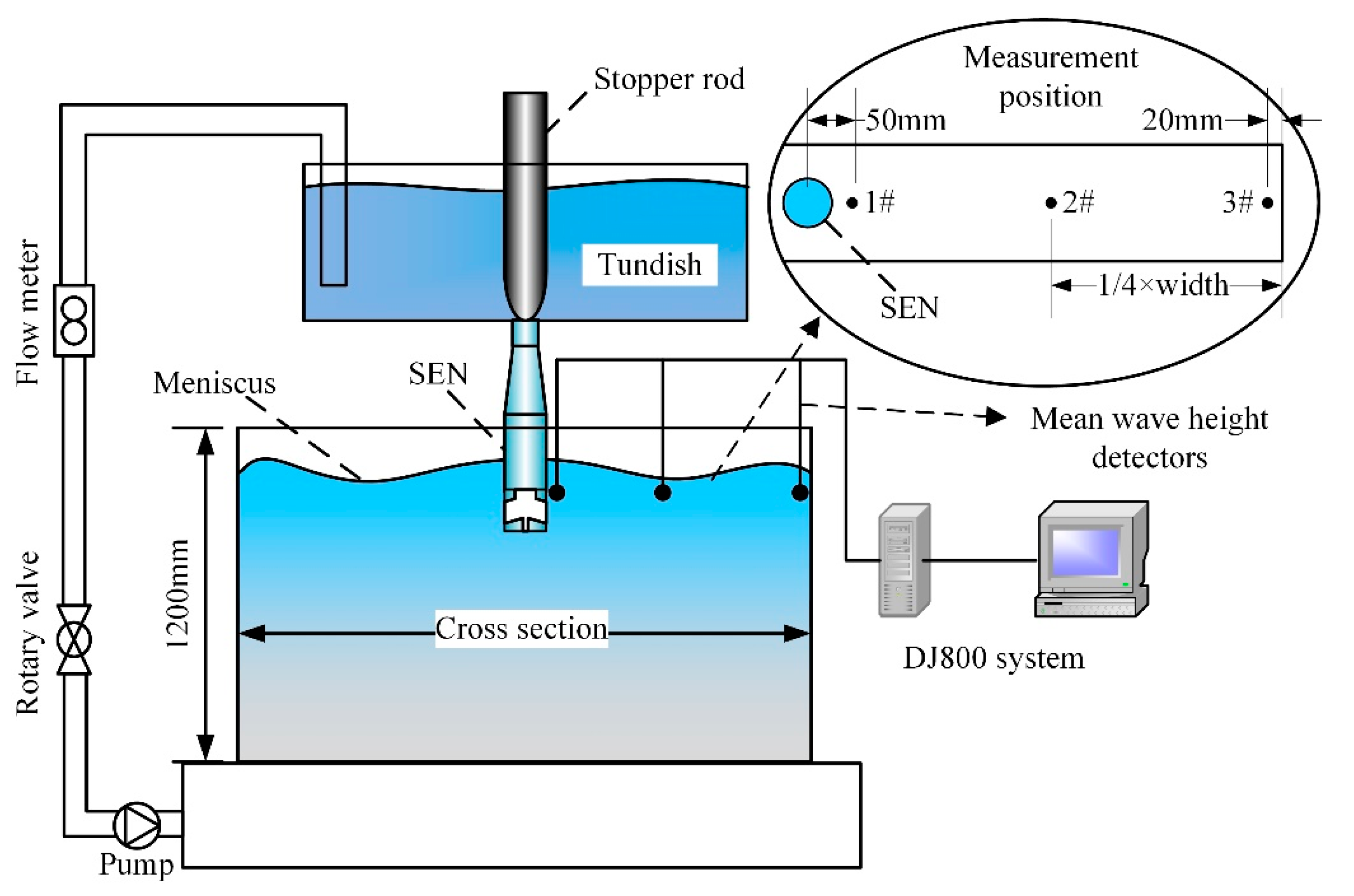
2.1. Physical Modeling

Based on the similarity principle, a 0.5:1 scale model mold of transparent plastic was fabricated with the dimensions of 75 × (510–770) mm2. As shown in Figure 1, the model was connected with a water pool equipped with a submerged pump to elevate water to a tundish, and the water was recycled during the experiment process with the flow meter controlling the flow rate. The fluctuation of free surface in the model mold was evaluated by mean wave height, measured using the sensors set along the symmetric plane along the width direction, including the positions of near the narrow face, a quarter width and near the SEN. In addition, the fluid flow pattern in the mold was displayed using color ink as a tracer. Details of the experimental setup can be found elsewhere [8,33].
The schematic of typical SENs is shown in Figure 2. Three designs of the oblate SEN, including the original one and the two modified ones with three-ports (3P), were investigated by comparing the influence of SEN designs (shown in Table 1) on fluid flow. From the parameters of the 3P-0 to the 3P-2, it is observed that the modification of the ports includes the change of the downward angle of the side ports and the cross-section area of the bottom port. The parameters of the actual and experimental model are shown in Table 2.

2.2. Mathematical Modeling

2.2.1. Governing Equations

All of the governing equations, including one continuity equation, three momentum equations (three directions), one energy equation and two turbulence equations of the standard k-ε model, can be written as follows [11]:
( ρ u i φ ) x i = x i ( Γ φ φ x i ) + S φ
where ρ is the fluid density, kg/m3; ui is the speed in i direction, m/s; φ is the variables, including velocities at three directions, temperature, enthalpy, turbulent kinetic energy and dissipation rate, xi is the direction, Γφ is the coefficient of diffusion and Sφ is the source term.
To describe the effect of solidification of molten steel on the flow and heat transfer in the mold, additional source terms (Smon and Stur) are added to the momentum equation and turbulence equations, as shown in Equations (2) and (3).
S mom = A mushy ( 1 f l ) 2 f l 3 + ξ ( u i u c , i )
S tur = A mushy ( 1 f l ) 2 f l 3 + ξ ϕ tur
where Amushy is the mushy zone constant, which is set to be 1.0 × 10⁸ [12]; fl is the liquid fraction which is assumed to vary linearly between the liquidus temperature and solidus temperature; ξ is a small constant (0.0001); uc,i is the moving speed of the solidified shell, m/s; and ϕtur represents the turbulence quantity.

2.2.2. Initial and Boundary Conditions

Considering the possible existence of backflow at the mold exit, the computational domain was extended to 3000 mm for the practical mold in the casting direction. The specific boundary conditions were given as follows:
(1)
The inlet velocity was determined by the inlet area, casting speed and cross-sectional area of mold, the initial and inlet temperature were both assumed to be the sum of the liquidus temperature and the superheat;
(2)
As the relative height of the level variations was usually small, the free surface was defined as the flat and adiabatic surface with zero-shear force [6,11,12,13,20,22,23];
(3)
The full development flow boundary condition was adopted at the outlet plane, which means that the gradients of all variables were set to zero in the normal direction;
(4)
Following the previous approach [7], a square-root function simplification of the local heat profile was loaded into the mold, and a constant convective heat transfer coefficient was loaded into the secondary cooling zone.

2.2.3. Numerical Procedure

Considering the complexity of the nozzle structure, tetrahedral cells were created around the SEN to capture the detailed geometric features, and hexahedral cells were created in other regions to reduce computational cost. The total number of the cells was about 160,000 and 330,000 for the mold width of 1020 mm and 1540 mm, respectively. The SIMPLE algorithm was applied to discrete the governing equations. When the residual for the energy equation was smaller than 10−6 and others were smaller than 10−4, the converged solution was assumed to be achieved. The thermo-physical properties of the steel used for simulation are listed in Table 3.

2.2.4. Modeling Verification and Plant Measurement

To verify the accuracy of the simulation result, the numerical simulation results of the fluid flow were compared with the results of the physical simulation. In addition, the velocity near the free surface in the practical mold during the steady state were tested according to the nail-dipping method, namely, several pairs of 5-mm-diameter, 300-mm-long stainless-steel nails, spaced 100 mm apart, were dipped for 3 s at 2-min intervals, at 10 mm from the SEN. The diameter and height difference of the solidified lump on each nail was used to estimate velocity magnitude according to the empirical formula. From the resulting histories of velocity magnitude, the time average of each velocity component was evaluated to validate the model predictions [16].

3. Results and Discussion

3.1. Fluid Flow Characteristic and Temperature Distribution with the 3P-0 SEN

Figure 3 shows the comparison of the numerical and physical simulation results of flow patterns in the model with the 3P-0 SEN. It is observed that the jet flow in Figure 3a is similar to the streamline in Figure 3b at the same operating parameters, indicating that the flow pattern is captured well by the numerical simulation. Similar to the common casting mold, it is also observed that the jet flow exiting the side ports of the SEN forms the typical “double-roll flow” [6] pattern after impacting the narrow face where they are split into two loops. One loop travels up along the narrow wall to the meniscus and then flows towards the SEN, forming the upper recirculation flow. Meanwhile, the other loop forms a lower recirculation flow that travels downwards to the deep position of the liquid pool. In addition, the molten steel flow exiting the bottom port forms a central jet and travels downward to the deeper position than the lower recirculation flow. It is considered that the stronger central jet goes against the removal of non-metallic inclusions and heating releasing of the molten steel during the practical continuous casting process. However, the existence of the central jet contributes to decreasing the momentum of the side jet and depressing the level fluctuation.
The results of water model experiments showed that the most severe position of the level fluctuation was near the narrow surface (Position 3#), and the measured results under different casting speeds for the three mold widths are shown in Figure 4. In this study, the impacting depth was defined as the deepest location of color ink injected into the water model for 1 s. For the mold width of 1020 mm, the mean wave height near the narrow face increased from 3.7 mm to 4.8 mm when the casting speed was increased from 2.6 m/min to 3.0 m/min (corresponding to the throughput from 3.10 t/min to 3.58 t/min). Furthermore, it is also observed that the mean wave height increased with the increment of mold width. For the mold width of 1540 mm, it was increased from 6.1 mm to 7.1 mm when the casting speed increased from 2.0 m/min to 2.2 m/min (corresponding to the throughput from 3.60 t/min to 3.96 t/min). At the same time, the mean wave height increased obviously with the mold width at the same throughput since the side jet deflected upward on the way to the narrow face. According to previous research [31], the mean wave height for the medium-thin slab casting mold should be controlled below 5.0 mm to prevent improper distribution and entrapment of the liquid mold flux. Thus, it is considered that the 3P-0 SEN basically meets the requirements for the mold width of 1020 mm, but does not satisfy the requirements for the mold width of 1230 mm after casting speed increased, and does not satisfy the requirements for the width of 1540 mm even under the present casting speed.
Figure 5 shows the influence of the SEN submergence depth on mean wave height and impacting depth. It is observed that, for the mold width of 1020 mm under the casting speed of 3.0 m/min, the mean wave height merely decreased from 6.2 mm to 4.6 mm while the SEN submergence depth increased from 80 mm to 140 mm, but the impacting depth obviously increased from 680 mm to 800 mm. For the mold width of 1540 mm under a casting speed of 2.2 m/min, the mean wave height merely decreased from 8.0 mm to 6.5 mm while the SEN submergence depth increased from 80 mm to 140 mm, but the impacting depth increased from 820 mm to 920 mm. As mentioned above, the strong central jet and the deep impacting depth go against the removal of non-metallic inclusion and heating releasing of the molten steel. Thus, although the increase of the SEN submergence depth would be conducive to decrease the level fluctuation in some degree, it is not recommended to be a good solution.
Figure 6 shows the influence of the SEN submergence depth on calculated temperature distribution at the central-symmetrical plane of the mold while the mold widths are of 1020 mm and 1540 mm under the casting speed of 3.0 m/min and 2.2 m/min, respectively. It is observed that the higher temperature zone moved down with the increase of the impacting depth, while the SEN submergence depth increased. For the mold width of 1020 mm under the submergence depth of 80 mm and 140 mm, the maximal temperature on the free surface was 1805.4 K and 1804.3 K, and it was 1805.3 K and 1804.4 K for the mold width of 1540 mm under these two submergence depths. In summary, the submergence depth had the greatest influence on the mean wave height (the maximal variation was 1.6 mm) and the impacting depth (the maximal variation was 120 mm) than the casting speed (the maximal variations were 1.1 mm and 60 mm, respectively) and the mold width (the maximal variations were 1.5 mm and 80 mm, respectively), but it decrease the temperature on the free surface by 0.9–2.1 K. Consequently, considering the temperature of molten steel near the free surface and its influence on the melting of the mold powder, it is also not recommended to depress the level fluctuation by increasing the SEN submergence depth while the casting speed increased. To satisfy the requirements of various mold sections, it is necessary to optimize the design of the SEN.

3.2. Effect SEN Geometric Parameters on Fluid Flow Characteristic and Temperature Distribution

Figure 7 shows the comparison of the mean wave height and impacting depth using different SENs at the maximal casting speeds. It is observed that the mean wave heights were 4.8 mm, 5.8 mm and 7.1 mm, respectively, for the three mold widths with the 3P-0 SEN. Using the 3P-1 SEN with the side port angle increased from 15° to 18°, the mean wave height decreased to 3.7 mm, 5.2 mm and 5.7 mm, respectively, indicating the increment of the side port angle effectively decreased the level fluctuation by depressing the upper recirculation flow. However, for the mold width of 1230 mm and 1540 mm, the mean wave heights were still over 5.0 mm. Thus, it is considered that this SEN still does not satisfy the requirement on casting at the maximal casting speed. Using the 3P-2 SEN (modified by slightly increasing the area of the bottom port of the 3P-1 SEN), the mean wave heights were 2.1 mm, 3.5 mm and 4.4 mm, respectively, for the three mold widths, indicating that the 3P-2 SEN well meets the requirement of level fluctuation of all the three mold widths. It is considered that the further decrease of the level fluctuation is due to the further weakening of upper recirculation flow caused by the decrease in the flow distribution of the side ports with the 3P-2 SEN.
In addition, it is observed from Figure 7b that, comparing to the 3P-0 SEN, the impacting depth slightly increased from 900 mm to 920 mm at the mold width of 1540 mm using the 3P-2 SEN. As mentioned above, the increase in impacting depth is not conducive to the removal of non-metallic inclusion and heating releasing that influence the formation of the solidified shell. As a result, it is considered that the temperature distribution of the liquid should be considered, especially the temperature at the mold exit.
Figure 8 shows the comparisons of the surface velocity and turbulent kinetic energy profile along the width direction of the level centerline plane while the 3P-0 and 3P-2 SENs were used under the submergence depth of 120 mm. The similar profile of the surface velocity and turbulent kinetic energy at each case indicated that the change in the SEN structure had little effect on the overall flow characteristic. It is observed that the maximal surface velocity was in the proximity of a quarter-width mold. With the 3P-0 SEN, the maximal surface velocities were 0.32 m/s and 0.47 m/s for the mold width of 1020 mm and 1540 mm, respectively. With the 3P-2 SEN, the maximal surface velocities in the two mold widths were 0.17 m/s and 0.38 m/s, respectively. These results indicate that the application of the 3P-2 SEN effectively decreased the maximal flow velocity on the free surface. It is observed from Figure 8b that the maximal turbulent kinetic energies were 7.43 × 10⁻³ m2/s2 and 7.91 × 10⁻³ m2/s2, respectively, while the 3P-0 SEN was used for the mold widths of 1020 mm and 1540 mm. The maximal turbulent kinetic energies were decreased to 2.93 × 10⁻³ m2/s2 and 3.62 × 10⁻³ m2/s2, respectively, while the 3P-2 SEN was used for these two mold widths. In addition, it is also observed from Figure 8a,b that the profiles turned gentle and the variation ranges decreased while the 3P-2 SEN was used instead of the 3P-0 one, which agrees with the results of Figure 7a and indicates that for all mold widths, the homogeneity of the active degree on the free surface along width direction was modified. Thus, the application of the 3P-2 SEN is considered favorable to the uniform distribution of temperature and melting of mold powder.
Figure 9 shows the temperature distribution profiles along the center-plane of the wide face for the mold widths of 1020 mm and 1540 mm with different SENs. It is observed that the maximum temperatures on the free surface and at the mold exit were decreased with the increase in the side port angle due to the weakened central jet and upper recirculation flow. It is also observed that the temperature in the proximity of the narrow face was slightly increased due to the enhanced lower recirculation flow, which has a negative impact on the breakout risk [13]. With the increase in the bottom port area, the enhanced central jet led to weakening the upper recirculation flow, which caused the side jet to move upward. Thus, more heat reached the free surface and the lower position of the liquid pool. As a result, it is observed that while the 3P-0 SEN was substituted by the 3P-2 SEN for the mold width of 1020 mm, the maximum temperature on the free surface was slightly increased from 1804.6 K to 1804.9 K, and the maximum temperature at the mold exit was slightly increased from 1804.4 K to 1804.8 K. While the 3P-0 SEN was substituted by the 3P-2 SEN for the mold of 1540 mm, the maximum temperature on the free surface was slightly increased from 1804.8 K to 1805.1 K, and the maximum temperature at the mold exit was increased from 1804.9 K to 1806.6 K. Although increasing the submergence depth was a more effective way to decrease the mean wave height than the increase of the side port angle (the maximal variation was 1.4 mm) and the bottom port area (the maximal variation was 1.6 mm), the increase in the bottom port area could increase the surface temperature, which was beneficial for the melting of the mold powder. Though the increase in temperature at the mold exit depresses the formation of the solidified shell, it is considered that the influence of such slight change of temperatures is limited. Therefore, the optimized SEN structure significantly modified the level fluctuation properties but did not obviously influence the temperature distribution.

3.3. Practical Measurement and Application Performance

Figure 10 shows the comparison of the practically measured free surface velocities while the 3P-0 SEN and the 3P-2 SEN were used under the maximal casting speed of the three mold widths and the submergence depth of 120 mm; IR and OR in the figure represent the positions of the inner radius and outer radius. As in the previous work [16], it is observed that the velocity near the outer radius was higher than that near the inner radius. Particularly, for the mold widths of 1020 mm, 1230 mm and 1540 mm, the maximal velocities are observed at the position of 300 mm, 400 mm and 500 mm, respectively, apart from the mold center. With the 3P-0 SEN, the maximal velocity was 0.32 m/s, 0.42 m/s and 0.49 m/s, respectively, for the three mold widths, and it was decreased to 0.28 m/s, 0.32 m/s and 0.38 m/s, respectively, with the 3P-2 SEN, indicating the performance of the optimized SEN structure on depressing the level fluctuation. In addition, it is also observed that the variation range for the three mold widths were all decreased while the 3P-2 SEN was used instead of the 3P-0 SEN, which further confirmed the performance of the 3P-2 SEN on the uniform of the level fluctuation along mold width direction. According to the practical experience and the technical requirement, the free surface velocity in the range of 0.2 m/s to 0.4 m/s, which is considered to satisfy the practical requirements.
The statistics data of practical production showed that the surface quality of the medium-thin slab was effectively improved by the application of the 3P-2 SEN after the throughput was increased to 3.96 t/min, with the breakout rate decreasing from 0.349% to 0.107% and the surface defect decreasing from 0.54% to 0.19%. In brief, it is concluded that the structure optimization of SEN effectively satisfied the requirement of increasing the capacity of the ASP caster.

4. Conclusions

Based on physical and numerical simulations, the effects of the structure of SENs and operating parameters on fluid flow characteristics and temperature distribution of the ASP mold with three widths were investigated, and the conclusions could be drawn as follows:
(1)
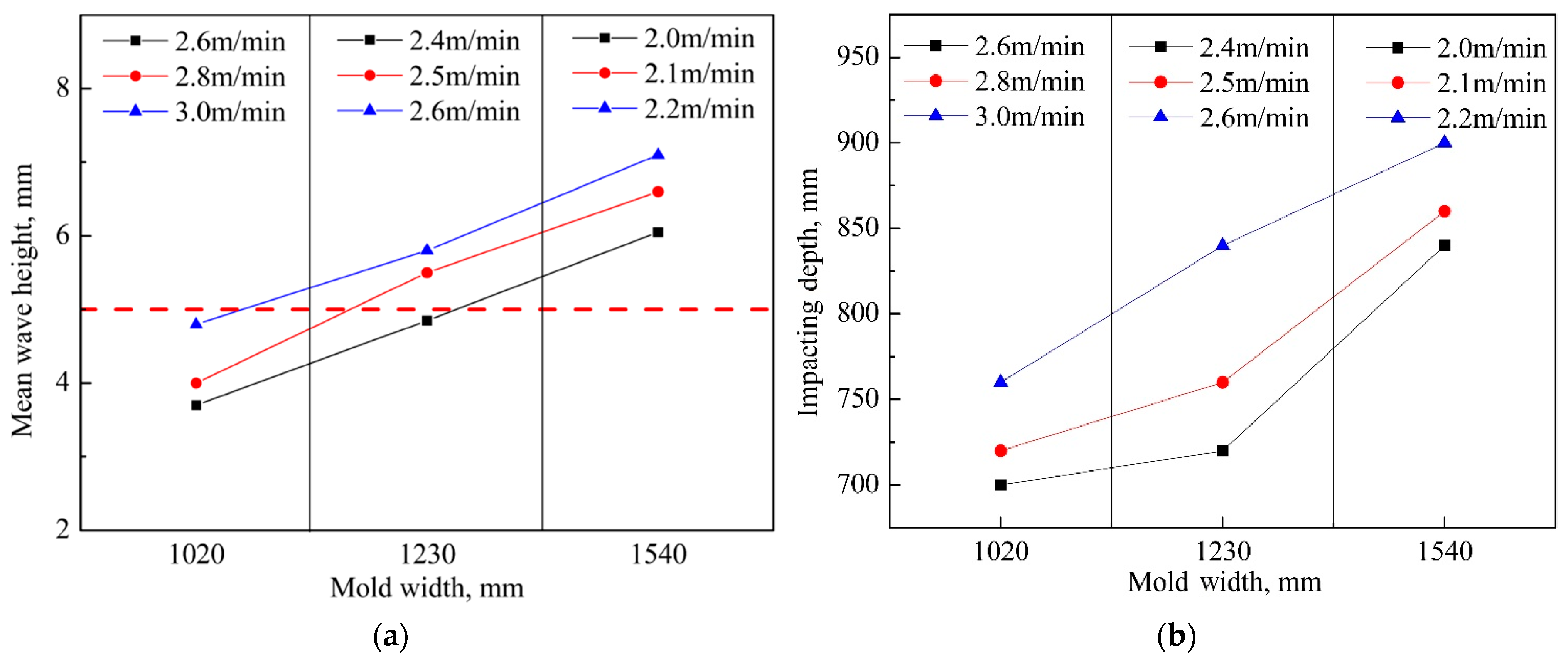
The flow pattern in the ASP mold could be described as a typical “double-roll” flow formed by the jet from the side port and a central jet from the bottom port, and the flow field and temperature distribution were strongly dependent on the SEN structure design except for the casting speed and the SEN submergence depth. Particularly, the level fluctuation was enhanced with the increment of mold width at the same throughput.
(2)
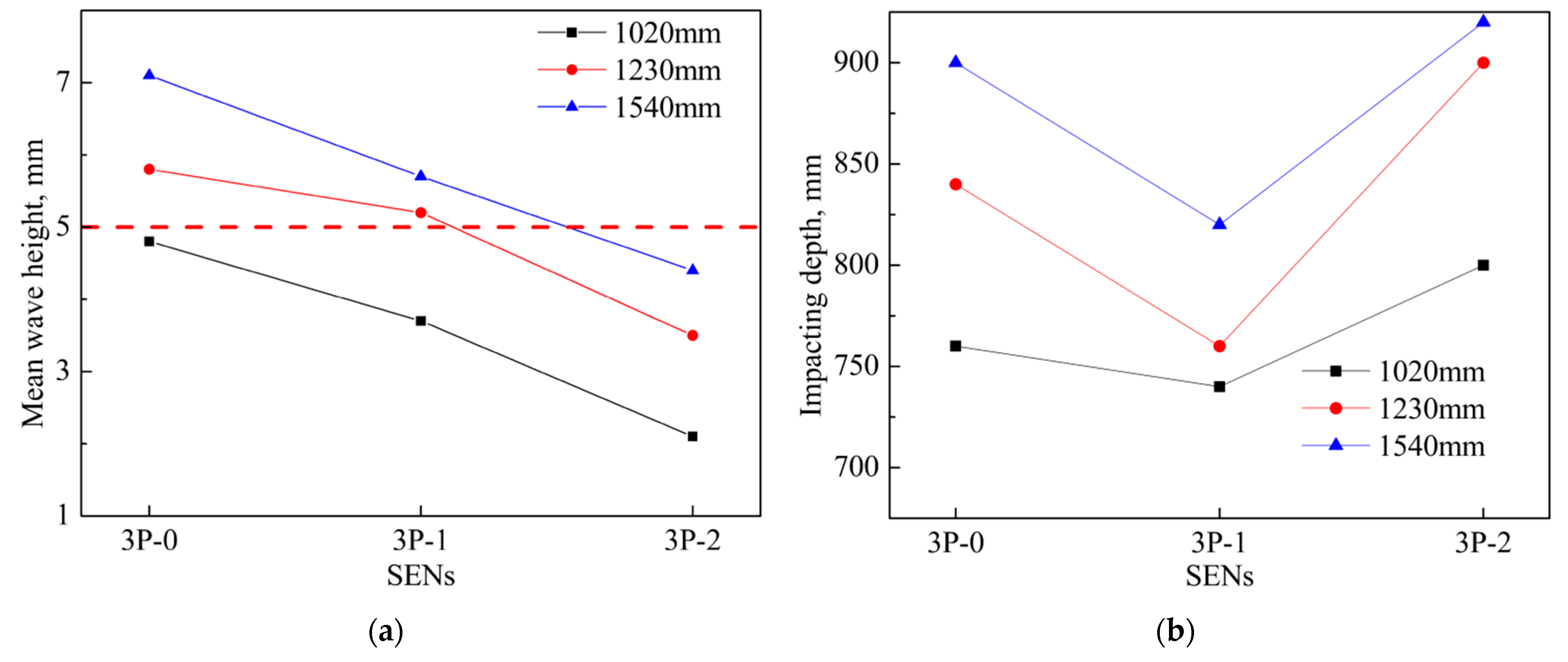
The 3P-0 SEN did not satisfy the requirement on increasing casting speed due to strong level fluctuation, with the mean wave heights of 4.8 mm, 5.8 mm and 7.1 mm, respectively, for the three widths of mold. At the same time, the optimization of the SEN structure design by increasing the side port angle and bottom port area could effectively depress the level fluctuation, with the mean wave height below 4.4 mm for the three widths of mold.
(3)
The temperature distribution was slightly changed by the application of the optimized SEN, with the maximum temperature increased to about 1.7 K at the mold exit and 0.3 K on the free surface.
(4)
Practical application performance showed that the surface quality of the medium-thin slab was effectively improved by the application of the 3P-2 SEN after the throughput was increased to 3.96 t/min, with the breakout rate decreased from 0.349% to 0.107% and the surface defect decreased from 0.54% to 0.19%.

Author Contributions

M.C. and M.X. conceived and designed the study and discussed the results; M.X. carried out the numerical simulation and wrote the paper; M.C. edited the manuscript. Both authors have read and agreed to the published version of the manuscript.

Funding

This research was funded by the National Natural Science Foundation of China, grant number 51774073, 51974080.

Data Availability Statement

All data generated or analyzed during this study are included in this published article.

Conflicts of Interest

No potential conflict of interest was reported by the authors.

References

  1. Liu, Y.; Wang, X.; Sun, Y.; Yao, M.; Gao, Y.; Wang, F.; Wang, J. Research on a new detection method of slab surface crack in mould during continuous casting. Metall. Res. Technol. 2017, 115, 108. [Google Scholar] [CrossRef]
  2. Dos Anjos, T.P.D.; De Cassia Lima Pimenta, P.V.; Marcondes, F. Analysis of the heat transfer coefficients of the whole process of continuous casting of carbon steel. J. Braz. Soc. Mech. Sci. Eng. 2018, 40, 107. [Google Scholar] [CrossRef]
  3. Li, Y.; Li, L.; Zhang, J. Study and application of a simplified soft reduction amount model for improved internal quality of continuous casting bloom. Steel Res. Int. 2017, 88, 1700176. [Google Scholar] [CrossRef]
  4. Botelho, T.; Medeiros, G.; Ramos, G.L.; Costa e Silva, A. The application of computational thermodynamics in the understanding and control of clogging and scum in continuous casting of steel. J. Phase Equilib. Diffus. 2017, 38, 201–207. [Google Scholar] [CrossRef]
  5. Jin, K.; Vanka, S.P.; Thomas, B.G. Large eddy simulations of the effects of EMBR and SEN submergence depth on turbulent flow in the mould region of a steel caster. Metall. Mater. Trans. B 2016, 48, 162–178. [Google Scholar] [CrossRef]
  6. Asad, A.; Kratzsch, C.; Schwarze, R. Numerical investigation of the free surface in a model mold. Steel Res. Int. 2016, 87, 181–190. [Google Scholar] [CrossRef]
  7. Liu, H.; Yang, C.; Zhang, H.; Zhai, Q.; Gan, Y. Numerical simulation of fluid flow and thermal characteristics of thin slab in the funnel-type molds of two casters. ISIJ Int. 2011, 51, 392–401. [Google Scholar] [CrossRef] [Green Version]
  8. Deng, X.; Ji, C.; Cui, Y.; Li, L.; Yin, X.; Yang, Y.; McLean, A. Flow pattern control in continuous slab casting moulds: Physical modelling and plant trials. Ironmak. Steelmak. 2017, 44, 461–471. [Google Scholar] [CrossRef]
  9. Shen, J.L.; Chen, D.F.; Xie, X.; Zhang, L.L.; Dong, Z.H.; Long, M.J.; Ruan, X.B. Influences of SEN structures on flow characters, temperature field and shell distribution in 420 mm continuous casting mould. Ironmak. Steelmak. 2013, 40, 263–275. [Google Scholar] [CrossRef]
  10. Calderón-Ramos, I.; Morales, R.D. The role of submerged entry nozzle port shape on fluid flow turbulence in a slab mold. Metall. Mater. Trans. B 2015, 46, 1314–1325. [Google Scholar] [CrossRef]
  11. Xu, M.; Zhu, M. Transport phenomena in a beam-blank continuous casting mold with two types of submerged entry nozzle. ISIJ Int. 2015, 55, 791–798. [Google Scholar] [CrossRef] [Green Version]
  12. He, M.; Wang, N.; Chen, M.; Xuan, M. Physical and numerical simulation of the fluid flow and temperature distribution in bloom continuous casting mold. Steel Res. Int. 2017, 88, 1600447. [Google Scholar] [CrossRef]
  13. Liu, R.; Blazek, K.; Forman, B.; Fritz, C.; Graham, C. Effect of submerged-entry nozzle (SEN) design on fluid flow and heat transfer in a thin-slab steel caster. Steel Res. Int. 2019, 90, 1800398. [Google Scholar] [CrossRef]
  14. Salazar-Campoy, M.M.; Morales, R.D.; Najera-Bastida, A.; Calderon-Ramos, I.; Cedillo-Hernandez, V.; Delgado-Pureco, J.C. A physical model to study the effects of nozzle design on dispersed two-phase flows in a slab mold casting ultra-low-carbon steels. Metall. Mater. Trans. B 2018, 49, 812–830. [Google Scholar] [CrossRef]
  15. Real-Ramirez, C.A.; Carvajal-Mariscal, I.; Sanchez-Silva, F.; Cervantes-De-La-Torre, F.; Diaz-Montes, J.; Gonzalez-Trejo, J. Three-dimensional flow behavior inside the submerged entry nozzle. Metall. Mater. Trans. B 2018, 49, 1644–1657. [Google Scholar] [CrossRef]
  16. Cho, S.M.; Thomas, B.G.; Kim, S.H. Effect of nozzle port angle on transient flow and surface slag behavior during continuous steel slab casting. Metall. Mater. Trans. B 2019, 50, 52–76. [Google Scholar] [CrossRef]
  17. Gan, M.; Pan, W.; Wang, Q.; Zhang, X.; He, S. Effect of exit shape of submerged entry nozzle on flow field and slag entrainment in continuous casting mold. Metall. Mater. Trans. B 2020, 51, 2862–2870. [Google Scholar] [CrossRef]
  18. Calderon-Ramos, I.; Morales, R.D.; Servin-Castaneda, R.; Perez-Alvarado, A.; Garcia-Hernandez, S.; Barreto, J.D.J.; Arreola-Villa, S.A. Modeling study of turbulent flow in a continuous casting slab mold comparing three ports SEN designs. ISIJ Int. 2019, 59, 76–85. [Google Scholar] [CrossRef] [Green Version]
  19. Li, B.; Lu, H.; Shen, Z.; Sun, X.; Zhong, Y.; Ren, Z.; Lei, Z. Physical modeling of asymmetrical flow in slab continuous casting mold due to submerged entry nozzle clogging with the effect of electromagnetic stirring. ISIJ Int. 2019, 59, 2264–2271. [Google Scholar] [CrossRef] [Green Version]
  20. Li, B.; Lu, H.; Zhong, Y.; Ren, Z.; Lei, Z. Numerical simulation for the influence of EMS position on fluid flow and inclusion removal in a slab continuous casting mold. ISIJ Int. 2020, 60, 1204–1212. [Google Scholar] [CrossRef]
  21. Li, Z.; Zhang, L.; Ma, D.; Wang, E. Numerical simulation on flow characteristic of molten steel in the mold with freestanding adjustable combination electromagnetic brake. Metall. Mater. Trans. B 2020, 51, 2609–2627. [Google Scholar] [CrossRef]
  22. Schurmann, D.; Glavinic, I.; Willers, B.; Timmel, K.; Eckert, S. Impact of the electromagnetic brake position on the flow structure in a slab continuous casting mold: An experimental parameter study. Metall. Mater. Trans. B 2020, 51, 61–78. [Google Scholar] [CrossRef]
  23. Han, S.W.; Cho, H.J.; Jin, S.Y.; Seden, M.; Lee, I.B.; Sohn, I. Effects of simultaneous static and traveling magnetic fields on the molten steel flow in a continuous casting mold. Metall. Mater. Trans. B 2018, 49, 2757–2769. [Google Scholar] [CrossRef]
  24. Xu, L.; Wang, E.; Karcher, C.; Deng, A.; Xu, X. Numerical simulation of the effects of horizontal and vertical EMBR on jet flow and mold level fluctuation in continuous casting. Metall. Mater. Trans. B 2018, 49, 2779–2793. [Google Scholar] [CrossRef]
  25. Lee, J.H.; Han, S.; Cho, H.J.; Park, I.S. Numerical and experimental study of the meniscus vortex core in a water model of continuous casting mold. Metall. Mater. Trans. B 2021, 52, 178–189. [Google Scholar] [CrossRef]
  26. Zhang, K.T.; Liu, J.H.; Cui, H. Simulation for mass transfer kinetics at slag-steel interface during high al steel continuous casting. ISIJ Int. 2019, 59, 2256–2263. [Google Scholar] [CrossRef] [Green Version]
  27. Singh, V.; Das, S.K. Mathematical model and plant investigation to characterize effect of casting speed on thermal and solidification behavior of an industrial slab caster. ISIJ Int. 2018, 58, 2308–2317. [Google Scholar] [CrossRef] [Green Version]
  28. Zhao, P.; Zhou, L. Mathematical modelling of slag entrainment and entrained droplets in a continuous casting mould. Ironmak. Steelmak. 2019, 46, 886–895. [Google Scholar] [CrossRef]
  29. Zhang, K.T.; Liu, J.H.; Cui, H. Effect of flow field on surface slag entrainment and inclusion adsorption in a continuous casting mold. Steel Res. Int. 2020, 91, 1900437. [Google Scholar] [CrossRef]
  30. Zhao, H.; Wang, X.; Zhang, J.; Wang, W. Effect of SEN structure on the mold level fluctuation and heat transfer for a medium thin slab caster. J. Univ. Sci. Technol. B 2008, 15, 120–124. [Google Scholar] [CrossRef]
  31. Thomas, B.G.; O’Malley, R.; Shi, T.; Meng, Y.; Creech, D.; Stone, D. Validation of Fluid Flow and Solidification Simulation of a Continuous Thin-Slab Caster, Modeling of Casting, Welding, and Advanced Solidification Processes IX, Aachen, Germany, August 20–25; Sahm, P.R., Hansen, P.N., Conley, J.G., Eds.; Shaker Verlag GmbH: Aachen, Germany, 2000. [Google Scholar]
  32. Pfeiler, C.; Thomas, B.G.; Wu, M.; Ludwig, A.; Kharicha, A. Solidification and particle entrapment during continuous casting of steel. Steel Res. Int. 2008, 79, 599–607. [Google Scholar] [CrossRef] [Green Version]
  33. Gupta, D.; Lahiri, A.K. A water model study of the flow asymmetry inside a continuous slab casting mold. Metall. Mater. Trans. B 1996, 27, 757–764. [Google Scholar] [CrossRef]
Figure 1. Schematic of the water model and measurement positions of mean wave height.
Metals 11 01223 g001
Figure 2. Schematic of typical SENs investigated.
Metals 11 01223 g002
Figure 3. Comparison of (a) physical and (b) numerical simulation results of flow pattern in the model.
Metals 11 01223 g003
Figure 4. (a) Mean wave height and (b) impacting depth of three mold widths with 3P-0 SEN while the SEN submergence depth was 120 mm.
Metals 11 01223 g004
Figure 5. (a,c,e) Mean wave height and (b,d,f) impacting depth with 3P-0 SEN for the mold width of (a,b) 1020 mm, (c,d) 1230 mm and (e,f) 1540 mm.
Metals 11 01223 g005aMetals 11 01223 g005b
Figure 6. Calculated temperature distribution at the central-symmetrical plane with different submergence depths for the mold width of (a) 1020 mm and (b) 1540 mm.
Metals 11 01223 g006
Figure 7. (a) Mean wave height near narrow face and (b) impacting depth using different SENs.
Metals 11 01223 g007
Figure 8. Comparisons of the (a) surface velocity and (b) turbulent kinetic energy profile along width direction of the level centerline.
Metals 11 01223 g008
Figure 9. Temperature distribution profiles along the center-plane of wide face (a) on the surface and (b) at mold exit.
Metals 11 01223 g009
Figure 10. Comparison of practically measured free surface velocity at inner radius (IR) and outer radius (OR) using (a) 3P-0 SEN and (b) 3P-2 SEN.
Metals 11 01223 g010
Table 1. Parameters of SEN structure.
SENSide Port Angle
α, °
Bottom Port Area
A, mm2
3P-0151133.5
3P-1181133.5
3P-2181656.6
Table 2. Parameters of actual and experimental model.
ObjectMold Width, mmCasting Speed, m/minMold Thickness, mmEffective Length of Mold, mmSEN Submergence Depth, mm
Actual mold10202.6–3.0150110080–140
12302.4–2.6
15402.0–2.2
Physical model5101.84–2.127555040–70
6151.70–1.84
7701.41–1.56
Table 3. Thermo-physical properties of steel used for numerical simulation.
Parametervalue
Density, kg/m37000
Dynamic viscosity, kg/(m·s)0.0055
Specific heat, J/(kg·K)680
Thermal conductivity, W/(m·K)34
Liquidus temperature, K1804
Solidus temperature, K1769
Superheat, K25
Latent heat, J/kg270,000
Publisher’s Note: MDPI stays neutral with regard to jurisdictional claims in published maps and institutional affiliations.

