Abstract
This study investigated the evolution of microstructure and mechanical properties of 25 mm thick S11306 ferritic stainless steel welded joints during Post weld heat treatment (PWHT) by a series of tests, including the optical microscope observation, hardness test, tensile test, bending test, and scanning electron microscope tests. The experimental results show that at as-welded and 870 °C, the toughness of welded joints was poor; and when the heat treatment temperature is between 770 and 820 °C, the content of the composite phase of lower bainite and martensite (LB/M) in the weld zone increased to 43.9~47.6%, and the mean values of tensile strength and yield strength were 476 MPa and 309 MPa, the elongation was close to 40%, and the welded joints show good toughness. The bending test of the welded joints under several groups of PWHT was qualified. Heat preservation of welded joints was conducted at 820 °C for 30 s~1 h and with the increase of holding times, the content of the LB/M in weld zone showed an upward trend, and the recrystallization of base metal zone was basically completed at 15 min. In addition, a recrystallization kinetic model of the base metal zone was also established by measuring the hardness of the base metal zone at 820 °C for different holding times, which provides reference opinions for obtaining the favorable microstructure of steel grades during PWHT in the engineering.
1. Introduction
Due to the excellent stress corrosion resistance, good cold formability and plasticity, S11306 ferritic stainless steel has been widely used to manufacture linings of components and equipment that are resistant to water vapor, ammonium bicarbonate mother liquor and hot sulfur-containing petroleum corrosion. However, the as-welded microstructure of S11306 ferritic stainless steel is easily affected by welding heat input, leading to the coarse grains and an excessive width of coarse grains, which is manifest as the embrittlement of welded joints [1,2]. A reasonable post-welding heat treatment process is one of the main methods to solve the embrittlement problem of ferritic stainless steel thick plate welded joints.
A large number of scholars have studied the microstructure and mechanical properties of welded joints of ferritic stainless steel obtained by different welding processes. There are many welding methods for ferritic stainless steel, such as shielded arc welding (SMAW), gas metal arc welding (GMAW), and gas tungsten arc welding (GTAW) [3,4,5]. Urade et al. studied the metallographic structure and mechanical properties of welded joints of ultra-pure ferritic stainless steel, ferritic stainless steel, and austenitic stainless steel by different welding methods. The results showed that the metallographic structure of welded joints obtained by different welding methods is quite different, and the tensile strength and pitting corrosion resistance are also different [5,6,7,8]. Beata Skowronska et al. used the PTA-MAG (plasma transferred arc-metal active gas) method to weld the high yield strength, bullet resistant steel (1450 MPa) RAMOR 500 (martensitic structure in the initial state), and selected the optimal process parameters by analyzing the degree of material weakening in the heat affected zone. The results show that the martensitic steel welded with PTA-MAG mixed heat source is safe and efficient, and has no cold crack production, and the weakest area of the welding joint is located in the HAZ [9]. By studying the microstructure and mechanical properties of the welded joint of SAF2205 ultra-thick duplex stainless steel plate, Wan Yu et al. found that the change law of the mechanical properties of the welded joint along the transverse and thickness direction accord with the distribution law of metallographic structure [10]. In order to study the influence of different welding wires on the comprehensive properties of welded joints between stainless steel and ordinary steel, M Amra and Feng Shaonan used four kinds of welding wires to weld materials by manual arc welding. The results showed that different metallographic structures were obtained after welding with different covered electrode, which resulted in different comprehensive mechanical properties of welded joints [11,12]. Mazadehsh et al. studied the effect of resistance welding on the microstructure transformation of AISI430 ferritic stainless steel welded joint. The results showed that the microstructure of welded joint was columnar ferrite and martensite precipitated along the grain boundary, and the high temperature zone, middle temperature zone, and low temperature zone of heat affected zone were composed of different phases [13]. Many investigations have been performed on the as-welded microstructure and properties of stainless steel welded joints, but few studies concentrated on the their evolution during PWHT with different process parameters. Ma Yuanyuan and Zhang Xiong studied the recrystallization process of 0Cr13 and 430 stainless steels by different annealing processes. The results showed that 0Cr13 stainless steel can obtain uniform recrystallized ferrite structure after being cooled at 820 °C × 5 h, and the recrystallization kinetic model of 430 ferritic stainless steel was established by the hardness method [14,15]. Yue Xin studied the change of the strength of coarse grain zone of BA-160 high-strength explosion-proof steel after heat treatment at 650 °C for 1h after welding. The result showed that the strengthening phase precipitated in coarse grain zone after heat treatment not only reduced HIC (Hydrogen-Induced Cracking) sensitivity of BA-160 steel, but also increased the strength of coarse grain zone [16]. Prachya Peasura and Bernard Maxmillan Sim performed different post-welding heat treatment tests for UNS31803 and DMR249 duplex stainless steels, respectively. The results showed that the contents of ferrite and austenite phases were quite different at different heat treatment temperatures and holding times, and their mechanical properties such as hardness showed different characteristics [17,18]. Mallaiah et al. treated the welded joints of ferritic stainless steel at 830 °C for 30 min to study the effect of post-welding heat treatment on the mechanical properties of welded joints. The result showed that the welded joint has better tensile property, ductility, and pitting resistance under the condition of post-welding annealing, and the residual stress value is lower [19]. Zhang Min et al. treated 25Cr2Ni4MoV stainless steel with 920 °C × 1 h oil quenching and 580 °C × 1 h air cooling tempering before and after welding. It was found that the microstructure obtained by post-welding heat treatment was finer and more uniform, and the mechanical properties were better [20]. However, there are few literature reports on the post-welding heat treatment process of 25 mm thick S11306 ferritic stainless steel.
Therefore, this paper mainly studied the relationship between microstructure and mechanical properties of welded joints of S11306 stainless steel by different post-welding heat treatment processes, established the recrystallization kinetic model of base metal zone of S11306 ferritic stainless steel by the hardness method, determined the most reasonable post-welding heat treatment process, and solved the serious embrittlement problem of welded joints of 25 mm thick S11306 ferritic stainless steel.
2. Experimental Procedures
2.1. Materials
The 25 mm thick cold rolled S11306 ferritic stainless steel plate with dimensions of 400 mm × 300 mm × 25 mm was evaluated in this study, and electrode arc welding was used. The filler material was G207 ferrite stainless steel with Φ4 mm which was baked using a covered electrode at 300 °C for two hours before welding. Based on NB/T47010-2010 and NB/T47018.2, the chemical compositions of the plate and covered electrode are shown in Table 1, and the mechanical properties of the base metal zone is shown in Table 2. The ZX7-500S inverter DC arc welding machine (Aotai, Shandong, China) was used to weld the plate with 18 front welds and 2 back welds. The welding joint schematic diagram is shown in Figure 1. The plate spacing was 2 mm, and the interlayer temperature was controlled at 150 ± 5 °C during. The welding parameters are summarized in Table 3. Five groups of test plates were welded by the same welding process. All the test samples passed the nondestructive test.

Table 1.
Chemical composition of S11306 ferritic stainless steel and covered electrode G207.
Table 2.
Mechanical properties of S11306 ferritic stainless steel.
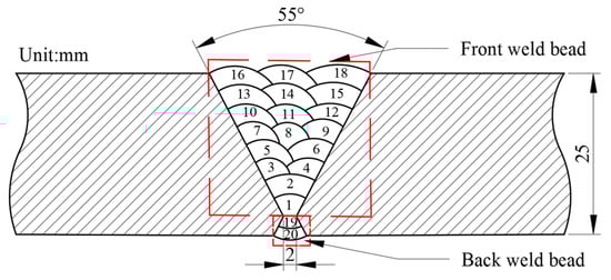
Figure 1.
S11306 schematic diagram of welded joint.
Table 3.
Welding process parameters.
2.2. Microstructural Characterization
Based on GB/T13298-2015 Standard “Inspection Method of Metal Microstructure”, a small sample of 15 mm × 5 mm × 5 mm was cut from the welded joint by TQY-06A electrospark wire-electrode cutting machine, and the metallographic sample was cut at a distance of 2.5 mm from the upper end face of the welded joint. Five groups of samples were cut, one in each group, including the weld zone (WZ), heat affected zone (HAZ) and base metal zone (BM). The sampling positions are displayed in Figure 2 and Figure 3. The distribution of metallographic microstructure of small samples was observed by 4XC inverted metallographic microscope (Shanghai No.5 Optical Instrument Factory Co., Ltd., Shanghai, China), and the number of microstructures and grain size were measured by the auxiliary software Image Pro Plus6.0. The etching solution was FeCl3, HCl and water solution in the ratio of 3 g:10 mL:80 mL, and the cotton was dipped in the etching agent at room temperature of 20 °C and wiped for 6~7 times until the surface brightness became dark.
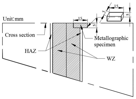
Figure 2.
Sampling diagram of metallographic sample.
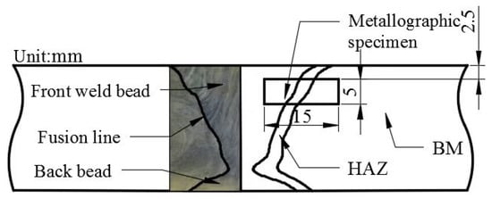
Figure 3.
Sampling diagram of metallographic specimen of welded joint.
2.3. Hardness Tests
Based on GB/T2654-2008 “Hardness Test Method for Welded Joints”, the hardness distribution of the whole S11306 welded joint was processed at room temperature. The location of the sampling points is displayed in Figure 4. A line parallel to the end face was drawn at a distance of 4 mm from the upper end face of the joint, and a testing point was drawn every 1 mm from the base material to the weld, for a total of 20 test points. The working load and holding time were 0.49 N and 15 s, respectively.
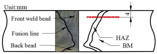
Figure 4.
Sampling diagram of hardness test point of welded joint.
2.4. Tensile and Bending Experiments
Based on NB/T47016-2011 “Mechanical Performance Inspection of Welded Specimens for Pressure Equipment Products”, the tensile and bending properties of S11306 welded joints were tested. The schematic diagrams of the tensile and bending parts are displayed in Figure 5 and Figure 6. Five groups of samples were prepared, and each group has two samples. The dimension specification of bending test is shown in Table 4. The WAW-1000B electro-hydraulic servo universal testing machine (Liangong Testing Equipment Co., Ltd., Shandong, China) was used in the test, and the displacement was controlled at 3 mm/min. Finally, the fracture morphology was observed by scanning electron microscope.
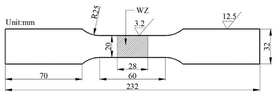
Figure 5.
Cross-sectional dimension of tensile specimen.
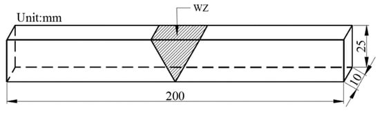
Figure 6.
Cut-out dimension of bending specimen.
Table 4.
Size regulation of bending test.
2.5. Determination of Heat Treatment Temperature
According to the measured chemical composition of S11306 ferritic stainless steel, the three-phase transformation temperature diagram of ferrite phase, austenite phase, and α-Cr phase was calculated by JMatPro software, as shown in Figure 7. Then, based on GBT30583-2014 “Post-Welding Heat Treatment Specification for Pressure Equipment”, four heat treatment temperatures with constant holding time of 2 h were considered, as shown in Figure 8. The flow chart of heat treatment with different holding time is shown in Figure 9.
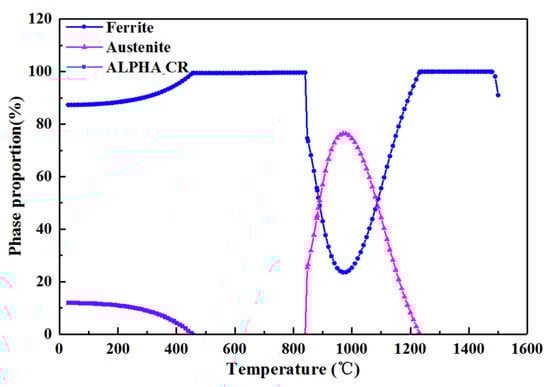
Figure 7.
Phase transition diagram.
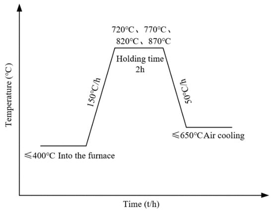
Figure 8.
Heat treatment parameters and flow chart.
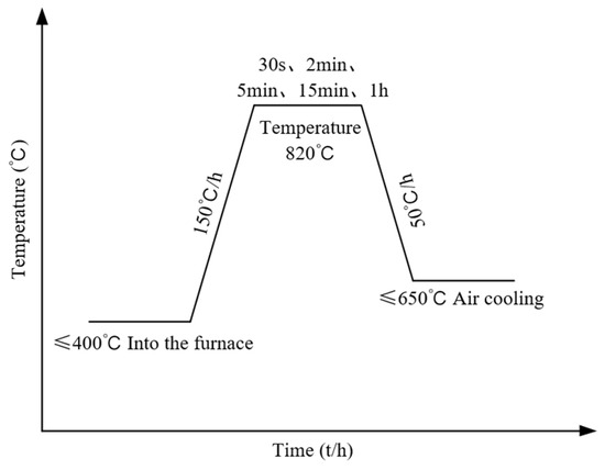
Figure 9.
Flow chart of heat treatment with different holding time.
3. Results and Discussion
3.1. Effect of Heat Treatment Temperature on Microstructure
The influence of heat treatment temperatures on the microstructure of the weld zone (WZ) is shown in Figure 10(1–5). The ferrite is always the matrix regardless of as-welded and after PWHT. However, for the as-welded condition, martensite and retained austenite are also observed, and when the heat treatment temperature is below 820 °C, the retained austenite is decomposes. Meanwhile, the martensite promoted the transformation of retained austenite into lower bainite, leading to the composite phase of lower bainite and martensite (LB/M). At 720 °C, the content of the LB/M accounts for about 37.2% of the total. With the increase in heat treatment temperature, the content of the LB/M increases. When the heat treatment temperature reaches 820 °C, the content of the LB / M reaches the maximum, accounting for about 47.6%. When the heat treatment temperature of 870 °C exceeds the phase transformation temperature of the base metal zone of 840 °C, and the low bainite content decreases, the newly formed austenite transforms into martensite during cooling, resulting in the increase of martensite.
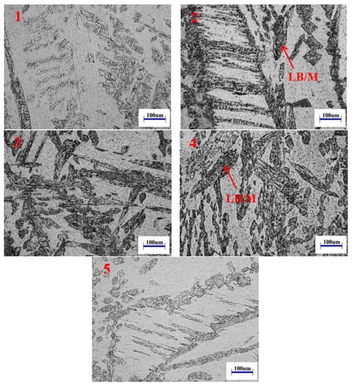
Figure 10.
Microstructure of weld zone at different heat treatment temperatures: (1) as-welded, (2) 720 °C, (3) 770 °C, (4) 820 °C, (5) 870 °C.
Figure 11(1–5) show the microstructure of the coarse grain zone (GCHAZ) at different heat treatment temperatures. At as-welded, the ferrite grain size in the GCHAZ is relatively small with an average grain size is approximately 152 μm, and a small amount of martensite distributes along the grain boundary. When the heat treatment temperature is below 840 °C, with the increase of heat treatment temperature, the ferrite grain size in the GCHAZ gradually increases. At 820 °C, the maximum grain size is about 286 μm, and the martensite structure gradually decomposes into carbide and dissolves into ferrite grain. When the heat treatment temperature exceeds the phase transformation temperature, the original ferrite transformed into austenite, resulting in an increase of martensite at the grain boundary after cooling compared with 820 °C. There is no obvious growth phenomenon of ferrite grains, because the newly formed martensite structure after phase transformation will cause a certain degree of phase transformation expansion, which inhibits the growth of ferrite grains at high temperature.
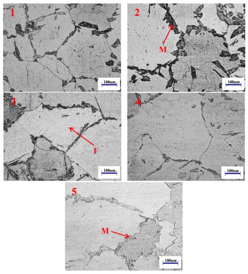
Figure 11.
Microstructure of coarse grain zone at different heat treatment temperatures: (1) as-welded, (2) 720 °C, (3) 770 °C, (4) 820 °C, (5) 870 °C.
Figure 12(1–5) show the microstructure of the base metal zone (BM) at different heat treatment temperatures. At as-welded, a large number of martensite structures distribute in the base metal zone along the rolling direction, accounting for 38.6%. At 720 °C, the average grain size of ferrite is about 97 μm, martensite is decomposed, and the amount of martensite in the base metal zone decreases by 55.7%. At 770 °C, the martensite structure at the grain boundary is obviously decomposed, the average grain size of the ferrite grains is about 136 μm, and a small amount of carbide precipitates in ferrite grains, mainly because the solubility of carbon solid-dissolved in ferrite decreases with the decrease of temperature at high temperature, and supersaturated carbon precipitates in grains, which will form carbide. At 820 °C, the ferrite grain boundaries and carbides in grains in the base metal zone increases further, and there is no obvious martensite structure at the grain boundaries. Moreover, the recrystallization process is basically completed at this temperature. When the heat treatment temperature is 870 °C, the carbide in the base metal area is decomposed, and ferrite grains grow with an average grain size of approximately 167 μm.
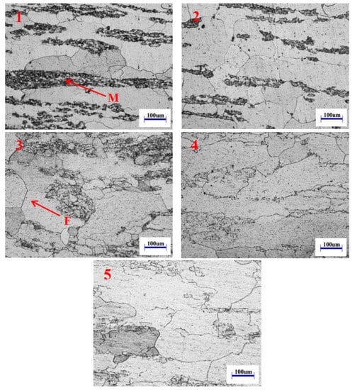
Figure 12.
Microstructure of base metal at different heat treatment temperatures: (1) as-welded, (2) 720 °C, (3) 770 °C, (4) 820 °C, (5) 870 °C.
3.2. Effect of Heat Treatment Time on Microstructure
In order to obtain a favorable microstructure and avoid the generation of unfavorable microstructure during annealing, the changes of metallographic structure and hardness were studied by changing the holding time form 30 s–1 h under constant heat treatment of 820 °C (recrystallization temperature), and complete recrystallization at 870 °C. The microstructure of the weld zone is shown in Figure 13(1–6). With the increase of holding time, the decomposition amount of retained austenite increases, and the content of the LB/M also increases. From 30 s to 5 min, the content of the LB/M increases by approximately 25.5%. When it reaches 15 min, the content of the LB/M accounts for approximately 46.7%. From 15 min to 1 h, the content of retained austenite decreases sharply, resulting in a slow increases of the LB/M. After complete recrystallization, the LB/M in the weld zone is decomposed at high temperature, and the content reduces by approximately 34.6%.
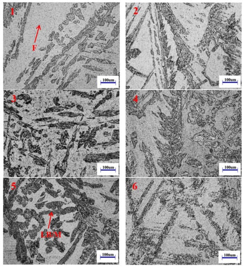
Figure 13.
Microstructure of weld zone at different holding times: (1) 30 s, (2) 2 min, (3) 5 min, (4) 15 min, (5) 1 h, (6) Complete recrystallization.
The microstructure of the GCHAZ is shown in Figure 14(1–6), where a small amount of intergranular martensite distributes at the ferrite grain boundary in the GCHAZ at 30 s, and the volume of martensite is small. With the prolongation of the holding time, the ferrite grain tends to grow up. The average grain size of ferrite is about 125 μm at 30 s, and the maximum grain size reaches to 265 μm after 1 h of holding. The existence of retained austenite at the grain boundary leads to the formation of more martensite structures in the cooling process after heat treatment. After holding for 15 min, the average grain size of the ferrite is approximately 250 μm, and the number of martensite grains increases significantly compared with that in 30 s. After holding for 1 h, the longer holding time makes martensite decompose more. After complete recrystallization, a uniform ferrite structure with the average grain size of approximately 115 μm is obtained.
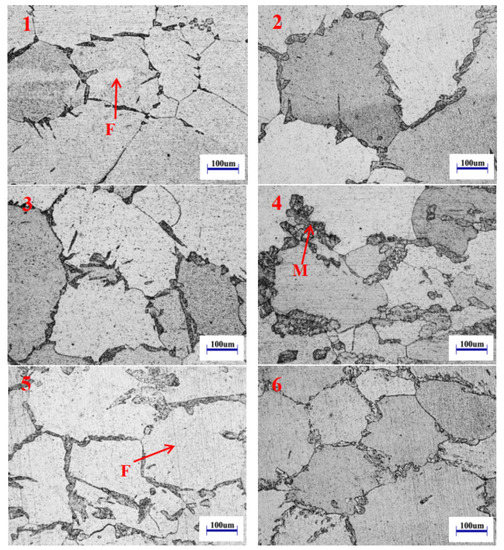
Figure 14.
Microstructure of coarse grain zone at different holding times: (1) 30 s, (2) 2 min, (3) 5 min, (4) 15 min, (5) 1 h, (6) Complete recrystallization.
Figure 15(1–6) show the microstructure of the base material area at different holding times. It can be seen that when the holding time is less than 2 min, there are about 35.8% recrystallized grains at the grain boundary, the grain size is relatively disordered, and there is no obvious growing-up phenomenon. The reason for this is that the grains prefer to nucleate inside, and growth takes place inside the grain by a large driving force. There are also carbides in ferrite grains, which make the grain size of ferrite uneven. When the holding time reaches 15 min, the deformed grains in the material decrease sharply and the fine grains grow slowly. The average size of the grains is about 167 μm. It can be seen that the dislocation density in the grains decreases and the grain boundary becomes more obvious under the action of recovery [21]. The grain size tends to be uniform, and the proportion of recrystallized grains further increases. However, the recrystallization process is not over yet. When the holding time reaches 1 h, the ferrite grains are mostly equiaxed, and the average size of the grains is approximately 174 μm. At this time, the recrystallization process of the material has been completed. After complete recrystallization, the grain size is approximately 125 μm, and carbide disperses and precipitates in the crystal.
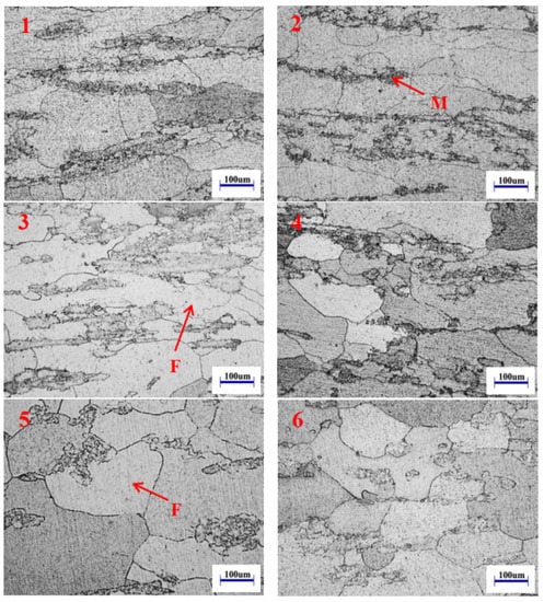
Figure 15.
Microstructure of base metal zone at different holding times: (1) 30 s, (2) 2 min, (3) 5 min, (4) 15 min, (5) 1 h, (6) Complete recrystallization (CR).
3.3. Hardness Distribution
The hardness distribution of the welded joints after 2 h of holding time at five different heat treatment temperatures is shown in Figure 16. At as-welded, the hardness of the base metal zone is the highest, at approximately 200 HV, and the hardness of the weld zone is slightly lower. With the increase of temperature, the hardness of the base metal zone decreases, according to Figure 12 which is mainly due to the decomposition of martensite, the higher the temperature is, the faster the recrystallization nucleation rate is, and when the microstructure is recrystallized, the growth of unstrained ferrite grains replaces the deformed grains; and with the increase of temperature, the content of α-Cr phase also decreases, so the hardness value generally decreases [22]. According to Figure 16 and Figure 17, after the heat treatment temperature exceeds 770 °C, the hardness value from base metal zone to the HAZ obviously increases, mainly because a large amount of martensite distributes at the ferrite grain boundary of the coarse grain zone under the action of welding thermal cycle, and the hardness of the HAZ is greatly increases due to the high strength and hardness of martensite itself [23]. As can be seen from Figure 10, when the heat treatment temperature is 720~820 °C, the content of the LB/M in the weld zone increases with the increase of heat treatment temperature, while both lower bainite and martensite have higher hardness, so the hardness of the weld zone increases accordingly. When the temperature exceeds the phase transformation temperature (840 °C), the LB/M in the weld zone is decomposed by heating at high temperature, and the content of the LB/M decreases, leading to the decrease of hardness. According to Figure 17, with the increase of heat treatment temperature, the average hardness of the BM decreases, and at as-welded and 720 °C, the average hardness of the WZ increases from 199.8 HV to 211.0 HV, and the hardness of HAZ has little changes. At 770 and 820 °C, the average hardness of WZ is 218.9 HV and 233.4 HV respectively, while the average hardness of BM is 181.1HV and 170.8 HV respectively. At 870 °C, the average hardness values of the BM, HAZ, and WZ of welded joints are 165.5 HV, 195.4 HV, and 199.0 HV respectively, which are lower than those of other cases. It can also be seen from Figure 17 that the hardness measurement error of the BM, HAZ, and WZ is very small regardless of the heat treatment temperature.
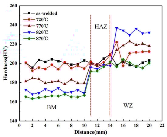
Figure 16.
Hardness distribution of welded joints at different heat treatment temperatures.
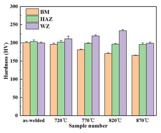
Figure 17.
Mean and error of hardness at different heat treatment temperatures.
The hardness distribution of the welded joints when holding at 820 °C for 30 s to 1 h and after complete recrystallization at 870 °C is shown in Figure 18 and Figure 19. When the time is 30 s and 2 min, the recrystallization process in the BM is in the gestation period, under the action of recovery, the hardness decreases slightly. When it reaches 5 min or more, the average hardness value of the BM drops rapidly to about 174 HV. On the one hand, with the increase of holding time, the original structure will recover, and the internal stress will be eliminated to some extent, which results in the decrease of hardness. On the other hand, according to Figure 15, the recrystallization rate of the BM increases rapidly after 5 min of heat preservation, when the recrystallized crystals grow greatly, the dislocation density decreases sharply, and the energy stored in the grains is consumed, resulting in the rapid decrease of hardness [24]. When time is 15 min and before, because the amount of the LB/M in the WZ increases less, the hardness of the WZ changes little. When the holding time reaches to 1 h, the content of the LB/M has increases rapidly, and the hardness value increases by nearly 20 HV. According to Figure 13, the longer the holding time, the higher the LB/M in the weld zone, and the higher the hardness. After complete recrystallization, the hardness of the HAZ is the highest, and the hardness of weld zone decreases obviously. As shown in Figure 19, with the increase of the heat treatment time, the hardness values of the BM and WZ have the same change trend as those at different heat treatment temperatures, and the average hardness values of the WZ and HAZ are sharply smaller, namely 182.1 HV and 184.9 HV, respectively. As shown in Figure 13 and Figure 14, the content of the LB/M decreases seriously, thus resulting in a decrease in the hardness value. The difference between the measurement points in the various regions is small, and only a few points can vary greatly due to the different grain size and phase of the indentation sampling. The size of the welding joint microhardness value decreases from the WZ to the BM at different heat treatment temperatures and different heat treatment times.
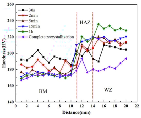
Figure 18.
Hardness distribution of welded joints under different heat treatment time.
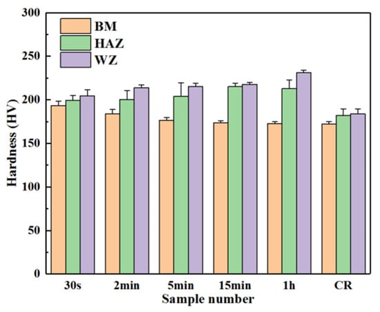
Figure 19.
Mean value and error of hardness at different heat treatment time.
3.4. Establishment of Recrystallization Kinetic Model
Recrystallization rate is an important parameter for establishing a recrystallization kinetic model and can be expressed by the change of recrystallization grain area ratio with time (metallographic method) and the change of hardness with time (hardness method). In this study, aiming at the change of hardness of the sample after recrystallization in the base metal zone after five groups of holding times of 30 s, 2 min, 5 min, 15 min, and 1 h at the fixed annealing temperature of 820 °C, the hardness method is selected to express the recrystallization rate X(t) in the recrystallization process, and its expression is as follows [25]:
where HVCR is the hardness in cold rolling state, HVFA is the hardness in complete annealing state, and HV(t) is the hardness of samples after different annealing times.
The relationship between recrystallization rate and holding time in the base material area calculated by hardness method and Formula (1) is shown in Figure 20. With the increase of holding time, the recrystallization rate rises sharply, and the recrystallization rate reaches more than 95% when the holding time reaches to 15 min. It can be seen that 820 °C is one of the main softening temperatures in the high-temperature continuous annealing process of this material.
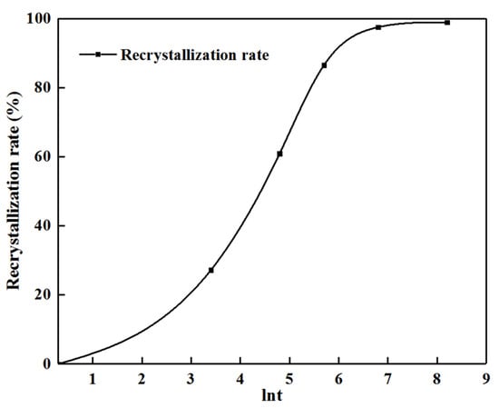
Figure 20.
Relationship between recrystallization rate and annealing time.
By controlling the holding time at this temperature, the favorable microstructure can be obtained, and the generation of unfavorable microstructure can be avoided. The Avrami recrystallization kinetics model is used to fit the recrystallization kinetics of samples, and the model equation is:
where X(t) is recrystallization rate, Z is constant, and n is Avrami constant; t is the annealing time, and the unit is s. Take the logarithm of both sides of the above formula to obtain the following relation:
Since Z and n are constants, this formula can be expressed as a linear relationship between lnln(1/1-X(t)) and lnt. The value n is the slope of the linear function, and the value lnZ is the intercept. Therefore, the experimental data can be linearly fitted to obtain the value n and the value Z by using the linear relationship. According to Formulas (2) and (3), the variation relationship between lnt and lnln(1/1−X(t)) is shown in Figure 21, and the values of Z and n are determined as 0.034 and 0.69 based on the least squares method, respectively.
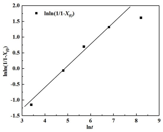
Figure 21.
The linear relationship between lnt and lnln(1/1−X(t)).
3.5. Tensile and Bending Properties
In order to further study the mechanical properties of welded joints at different heat treatment temperatures, five groups of welded joints after heat treatment were subjected to tensile and bending tests. Figure 22 shows the tensile data diagram, and Figure 23 shows the tensile results.
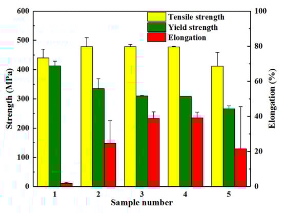
Figure 22.
Tensile test results: 1. as-welded, 2. 720 °C 3. 770 °C 4. 820 °C 5. 870 °C.
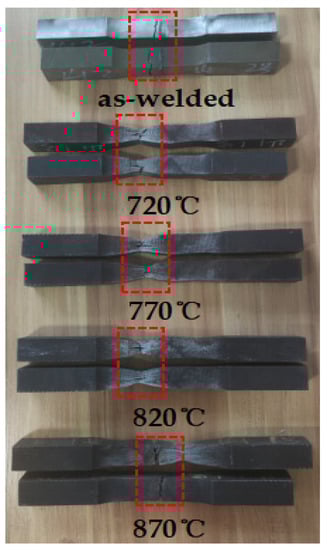
Figure 23.
Stretching result diagram.
Because the Cr content of the material used in the test is lower than 15%, and the heat preservation treatment is not carried out near 475 °C after welding and subsequent heat treatment, the welded joints will not be embrittled at 475 °C [26]. As shown in Figure 22 and Figure 23, at as-welded, there is more thick martensite tissue in the weld zone, due to the poor toughness of martensite, so the tensile fracture locates in the weld zone, the average values of tensile and yield strength are 440.0 MPa and 412.5 MPa, and the elongation is only 1.8%, the welded joint toughness is very poor. At 720 °C, the residual stress of the welded joint was removed [27]. At this time, the tensile strength increases to 478.0 MPa, while the yield strength reduces to 335.0 MPa, and the elongation reaches to 24.6%, and the toughness of the welded joint improves significantly. Combined with Figure 12(2), it is known that some martensite tissue still exists in the base metal zone at this temperature, resulting in the poor plastic toughness of the base metal zone, and the fracture is located in the base metal zone. Low tensile strength and yield strength are obtained at 870 °C, 411.5 MPa and 265.5 MPa, respectively. The elongation also reduces to 21.5%. Combined with Figure 10, Figure 11 and Figure 12, it is shown that the increase martensite tissue in the weld zone and the lower bainite tissue decreases, which reduces the toughness of the weld zone, but martensite tissue in the GCHAZ and the base metal zone is reduced, so the fracture is located in the weld zone.
At heat treatment temperatures of 770 and 820 °C, the residual stress after welding was effectively eliminated, and the content of the LB/M at the weld zone reaches approximately 45%, so the strength and toughness of the weld zone improve greatly, the martensite tissue in the GCHAZ decreases, and the recrystallization grain in the base metal zone increases, reducing the strength. The fracture occurs in the base metal zone, so it proved that the tensile strength and yield strength of the weld zone and the HAZ are higher than that of the base metal zone, i.e., super matching. The tensile strength of both heat treatment temperatures is 478.5 MPa and 477.5 MPa, respectively, the yield strength is 309.5 MPa and 309.0 MPa, respectively, while the elongation reaches more than 38% and improves the toughness significantly. As can also be seen from Figure 22, the error of the test data of the two groups after the heat treatment of 770 and 820 °C is very small, while in the remaining three cases, the difference between the two groups increases slightly due to factors, such as uneven tissue distribution.
For large pressure vessels, especially for thick plate welded joints, whether the bending test after welding is qualified is related to the safety of the whole equipment. According to the requirements of ASME section IX, when the length of convex crack in bending test is less than 3.2 mm, it is considered as qualified. As shown in Table 5 and Figure 24, at as-welded, the bending test occurred with serious fracture, and the fracture position is located in the weld zone, which is consistent with the results obtained in the tensile test, and it again shows that the weld zone has poor toughness due to excessive martensite without heat treatment. After heat treatment at different temperatures, these welded joints show good uniformity and full bending, with no cracks, indicating that these welded joints are continuous, dense, and have good plastic toughness, so they meet the acceptance standards of ASME Section IX [28].
Table 5.
Bending performance test report.
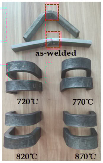
Figure 24.
Bending result diagram.
Figure 25(1–5) illustrate the SEM morphology of tensile fracture of S11306 ferritic stainless steel welded joints after different heat treatment temperatures. It can be seen that the fracture surface without heat treatment after welding shows a very small number of dimple features, while the rest are cleavage features. Combined with Figure 10(1), there are a large number of martensite structures in the weld zone, but the plasticity of martensite is poor, which leads to brittle fracture of the specimen. The fracture position is at the weld zone, corresponding to the result obtained by stretching. When the heat treatment temperature is 720 °C, it can be seen from Figure 12(2) that although there is more martensite in the base metal zone, the ferrite grain size tends to be uniform, so the dimples increase with deeper holes, and the fracture shown equiaxed dimples plus quasi-cleavage, which belongs to ductile-brittle fracture. At 770 and 820 °C, the number of dimples at the fracture reaches the maximum value. From Figure 12(3,4), it can be seen that martensite hardly existed in the base metal zone, the toughness of the base metal increases, and the number of holes increases, so the fracture shows ductile fracture. At 820 °C, the dimple size is the smallest, and a large number of dimples are formed mainly because the welded joint is subjected to the action of torque in tensile test, a dislocation plug is formed on the slip surface, the precipitates at the grain boundary form small holes after being separated from the matrix, and these small holes are gradually elongated and grow up under the action of normal stress. During tensile fracture, the crack will first appear on the interface with precipitates, and then drive the nearby metal to undergo plastic deformation to hinder the crack propagation, so that “necking” can only occur between inclusions and metal interfaces. When the normal stress increases to a certain value, the necking will be pulled off, and the holes in the metal will stick together continuously, resulting in the ductile fracture of the welded joint, resulting in a large number of dimples at the fracture [29,30]. At 870 °C, the number of dimples at the fracture decreases obviously. According to Figure 10(5), at this time, the number of martensite grains in the weld zone increases sharply, and the plasticity decreases rapidly, resulting in the increase of cleavage planes at the fracture, showing an obvious river-like appearance. The fracture position also appears at the weld zone, which belongs to brittle fracture. The fracture morphology characteristics of five groups of specimens are highly consistent with the tensile test results.
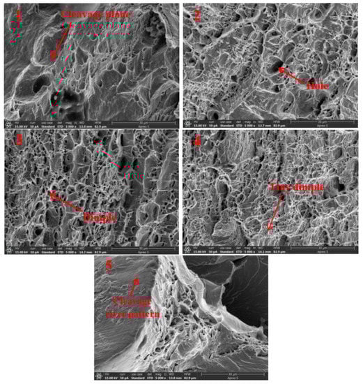
Figure 25.
Tensile fracture morphology at different heat treatment temperatures: (1) as-welded, (2) 720 °C, (3) 770 °C, (4) 820 °C, (5) 870 °C.
In this paper, the metallographic structure, microhardness, and mechanical properties of welded joints at different heat treatment temperatures are analyzed, and it is found that the comprehensive mechanical properties of 25 mm thick S11306 ferritic stainless steel after annealing at 770~820 °C are the best, which solves the embrittlement problem of welded joints with 25 mm thick plates. By measuring the hardness of welded joints with different holding times at 820 °C, the recrystallization kinetic model of the base metal zone is established, and this provides a useful reference value for industrial production.
4. Conclusions
In this study, S11306 ferritic stainless steel is treated by PWHT at different temperatures and holding times, its metallographic structure and mechanical properties are studied, and the following conclusions are drawn:
- (1)
- Before the heat treatment temperature does not exceed the transformation temperature of the base metal, with the increasing heat treatment temperature, the content of the LB/M increases from 25.6% to 47.6%, and the number of martensite grains decreases in GCHAZ and the base metal zone. When the heat treatment temperature exceeds the transformation point, the lower bainite in the weld zone decreases, martensite is regenerated in GCHAZ, and the amount of martensite increases.
- (2)
- The longer the heat treatment time, the more the LB/M in the weld zone, the more martensite in GCHAZ. When the holding time reaches 15 min, the grain size in the base metal zone tends to be uniform. The recrystallization process has been basically completed.
- (3)
- With the increase of heat treatment temperature and holding time, the hardness value of the base metal zone decreases. When the heat treatment temperature is 870 °C and after complete recrystallization, the hardness of the welded joint is the minimum.
- (4)
- At as-welded, the toughness of welded joints is extremely poor, and the tensile and bending test results are seriously unqualified. After heat treatment, some residual stress is eliminated. When heat treatment carries out at 770~820 °C, the tensile strength and yield strength of the welded joints both exceed 476 MPa and 309 MPa, respectively. Moreover, the elongation reaches more than 38%, which greatly improves the plasticity, thus solving the embrittlement problem of welded joints of thick plates made of this material.
- (5)
- The SEM fracture morphology observation shows a brittle fracture at as-welded and 870 °C. At 770 and 820 °C, the fracture is a toughness fracture, and the fracture morphology is highly consistent with the tensile test results.
Author Contributions
Conceptualization, X.H. and Y.Y.; methodology, Y.Y.; investigation, Y.Y. and Q.M.; writing—original draft preparation, Q.M. and Y.Y.; writing—review and editing, X.H. and Y.Y.; Translation and typesetting, X.H., Z.X. and Y.L.; project administration, X.H. and Y.Y.; funding acquisition, X.H. and Y.Y. All authors have read and agreed to the published version of the manuscript.
Funding
This work was supported by National Natural Science Foundation of Shandong Province (Grant No. ZR2022QE022), Key R&D plan of Shandong Province (Grant No. 2018GGX103019), Open Fundation of Shandong Provincial Key Laboratory of Mining Mechanical Engineering (Grant No. 2022KLMM310).
Data Availability Statement
The data used to support the findings of this study are included within the article.
Conflicts of Interest
The authors confirm that this article content has no conflict of interest.
References
- Zheng, H.; Ye, X.; Zhang, X.; Jiang, L.; Liu, Z.; Wang, G. Analysis of microstructure transformation, grain growth and precipitated phase in coarse grain zone of 12%Cr ferritic stainless steel. J. Weld. 2011, 32, 37–40+114–115. [Google Scholar]
- Zhao, Y.; Li, S.; Qu, H.; Liang, J. Effect of welding methods on microstructure and properties of welded joints of 430 stainless steel. Hot Process. Technol. 2020, 49, 137–140. [Google Scholar]
- Bolton, C.J.; Bischler, P.J.; Wootton, M.R.; Moskovic, R.; Morri, J.R.; Pegg, H.C.; Haines, A.B.; Smith, R.F.; Woodman, R. Fracture toughness of weld metal samples removed from a decommissioned Magnox reactor pressure vessel. Int. J. Press. Vessel. Pip. 2002, 79, 685–692. [Google Scholar] [CrossRef]
- Li, H.; Xing, W.; Yu, X.; Zuo, W.; Ma, L.; Dong, P.; Wang, W.; Fan, G.; Lian, J.; Ding, M. Dramatically enhanced impact toughness in welded ultra-ferritic stainless steel by additional nitrogen gas in Ar-based shielding gas. J. Mater. Res. 2016, 31, 3610–3618. [Google Scholar] [CrossRef]
- Cheng, M.; He, P.; Lei, L.; Tan, X.; Wang, X.; Sun, Y.; Li, J.; Jiang, Y. Comparative studies on microstructure evolution and corrosion resistance of 304 and a newly developed high Mn and N austenitic stainless steel welded joints. Corros. Sci. 2021, 183, 109338. [Google Scholar] [CrossRef]
- Hu, S.; Pang, J.; Shen, J.; Wu, W.; Liu, L. Microstructure, Mechanical Property and Corrosion Resistance Property of Cr26Mo3.5 Super Ferritic Stainless Joints by P-TIG and Laser Welding. Trans. Tianjin Univ. 2016, 22, 451–457. [Google Scholar] [CrossRef]
- Urade, V.P.; Ambade, S.P. An Overview of Welded Low Nickel Chrome-Manganese Austenitic and Ferritic Stainless Steel. J. Mater. Sci. Eng. 2016, 5, 1000231. [Google Scholar]
- Xie, Y.; Cai, Y.; Zhang, X.; Luo, Z. Characterization of keyhole gas tungsten arc welded AISI 430 steel and joint performance optimization. Int. J. Adv. Manuf. Technol. 2018, 99, 347–361. [Google Scholar] [CrossRef]
- Skowrońska, B.; Szulc, J.; Bober, M.; Baranowski, M.; Chmielewski, T. Selected properties of RAMOR 500 steel welded joints by hybrid PTA-MAG. J. Adv. Join. Process. 2022, 5, 100111. [Google Scholar] [CrossRef]
- Wan, Y.; Jiang, W.; Wei, W.; Xie, X.; Song, M.; Xu, G.; Xie, X.; Zhai, X. Characterization of inhomogeneous microstructure and mechanical property in an ultra-thick duplex stainless steel welding joint. Mater. Sci. Eng. A 2021, 822, 141640. [Google Scholar] [CrossRef]
- Amra, M.; Dehmolaei, R.; Alavi Zaree, S.R. On the Dissimilar Metal Welding of 1.4742 Ferritic to 310S Austenitic Stainless Steels Utilizing Different Filler Metals. Metallogr. Microstruct. Anal. 2019, 8, 623–641. [Google Scholar] [CrossRef]
- Feng, S.; Zhang, Y.; Cai, G.; Li, W. Study on the organization and performance of manual arc welding head of ZG28NiCrMo and 16Mn heterogeneous steel. Therm. Process. Process 2018, 47, 34–37+41. [Google Scholar]
- Alizadeh-Sh, M.; Marashi, S.P.H.; Pouranvari, M. Resistance spot welding of AISI 430 ferritic stainless steel: Phase transformations and mechanical properties. Mater. Des. 2014, 56, 258–263. [Google Scholar] [CrossRef]
- Ma, Y.; Bao, H.; Gong, Z.; Zhao, J.; Yang, G. Effects of heat treatment on the mechanical properties and magnetic properties of 0Cr13 steel. Met. Heat Treat. 2021, 46, 87–93. [Google Scholar]
- Zhang, X.; Wen, Z.; Dou, R.; Zhang, R.; Li, Z. 430 recrystallization tissue evolution and kinetic model of stainless steel cold rolled plate. J. Mater. Heat Treat. 2014, 35, 212–216. [Google Scholar]
- Xin, Y.; Feng, X.; Lippold, J.C. Strength increase in the coarse-grained heat-affected zone of a high-strength, blast-resistant steel after post-weld heat treatment. Mater. Sci. Eng. A 2013, 585, 149–154. [Google Scholar]
- Peasura, P.; Duangsrikaew, N.; Nansaarng, S. Application of Full Factorial Design for Post Weld Heat Treatment Parameters on Duplex Stainless Steel UNS31803. Adv. Mater. Res. 2013, 711, 178–182. [Google Scholar] [CrossRef]
- Sim, B.M.; Tang, S.H.; Alrifaey, M.; Tchan Jong, E.N. Analyzing the Effects of Heat Treatment on SMAW Duplex Stainless Steel Weld Overlays. Materials 2022, 15, 1833. [Google Scholar] [CrossRef]
- Mallaiah, G.; Reddy, P.R.; Kumar, A. Influence of Titanium Addition on Mechanical Properties, Residual Stresses and Corrosion Behaviour of AISI 430 Grade Ferritic Stainless Steel GTA Welds. Procedia Mater. Sci. 2014, 6, 1740–1751. [Google Scholar] [CrossRef]
- Zhang, M.; Tong, X.; Li, J.; Xu, S.; Sheena. Microstructure and properties of welded joints of 25Cr2Ni4MoV steel before and after quenching and tempering. Mech. Eng. Mater. 2021, 45, 34–40. [Google Scholar]
- Humpgrey, F. Recrystallization and Related Annealing Phenomena, 2nd ed.; Oxford Press: London, UK, 2004. [Google Scholar]
- Yang, J.; Zhou, W.; Lu, J.; Yu, F.; Xu, D.; Cao, W. Effect of α-Cr on microstructure and properties of new austenitic alloy after heat treatment. Steel 2015, 50, 84–91. [Google Scholar]
- Zhou, J.; Shen, J.; Hu, S.; Zhao, G.; Wang, Q. Microstructure and mechanical properties of AISI 430 ferritic stainless steel joints fabricated by cold metal transfer welding. Mater. Res. Express 2019, 6, 116536. [Google Scholar] [CrossRef]
- Yang, R.; Li, J.; Shu, J.; Sett, J. Static recrystallization behavior of 410S ferroite stainless steel. J. Lanzhou Univ. Technol. 2010, 36, 16–19. [Google Scholar]
- Yang, R.; Li, J.; Shu, J. Recrystallization kinetics of 410S hot rolled ferritic stainless steel. Trans. Mater. Heat Treat. 2010, 13, 94–98. [Google Scholar]
- Silva, R.; Kugelmeier, C.L.; Vacchi, G.S.; Junior, C.M.; Dainezi, I.; Afonso, C.R.; Mendes Filho, A.A.; Rovere, C.A. A comprehensive study of the pitting corrosion mechanism of lean duplex stainless steel grade 2404 aged at 475 °C. Corros. Sci. 2021, 191, 109738. [Google Scholar] [CrossRef]
- Kalyankar, V.D.; Chudasama, G. Effect of post weld heat treatment on mechanical properties of pressure vessel steels. Mater. Today Proc. 2018, 5, 24675–24684. [Google Scholar] [CrossRef]
- ASME. ASME, Boiler and Pressure Vessel Code Section IX; Qualifification Standard for Welding and Brazing Procedures, Welders, Brazers, and Welding and Brazing Operator; American Society of Mechanical Engineers: New York, NY, USA, 2010. [Google Scholar]
- Park, Y.S.; Sohn, I.S.; Bae, D.H. Fatigue strength assessment including welding residual stress of spot welded joints subjected to cross-tension loads. Int. J. Automot. Technol. 2014, 15, 765–771. [Google Scholar] [CrossRef]
- Matsuda, M.; Iwamoto, Y.; Morizono, Y.; Tsurekawa, S.; Takashima, K.; Nishida, M. Enhancement of ductility in B2-type Zr-Co-Ni alloys with deformation-induce martensite and microcrack formation. Intermetallics 2013, 36, 45–50. [Google Scholar] [CrossRef]


Disclaimer/Publisher’s Note: The statements, opinions and data contained in all publications are solely those of the individual author(s) and contributor(s) and not of MDPI and/or the editor(s). MDPI and/or the editor(s) disclaim responsibility for any injury to people or property resulting from any ideas, methods, instructions or products referred to in the content. |
© 2022 by the authors. Licensee MDPI, Basel, Switzerland. This article is an open access article distributed under the terms and conditions of the Creative Commons Attribution (CC BY) license (https://creativecommons.org/licenses/by/4.0/).