

Effects of Lubricating Conditions on Wear Performance of U77MnCrH Rail

Abstract
1. Introduction
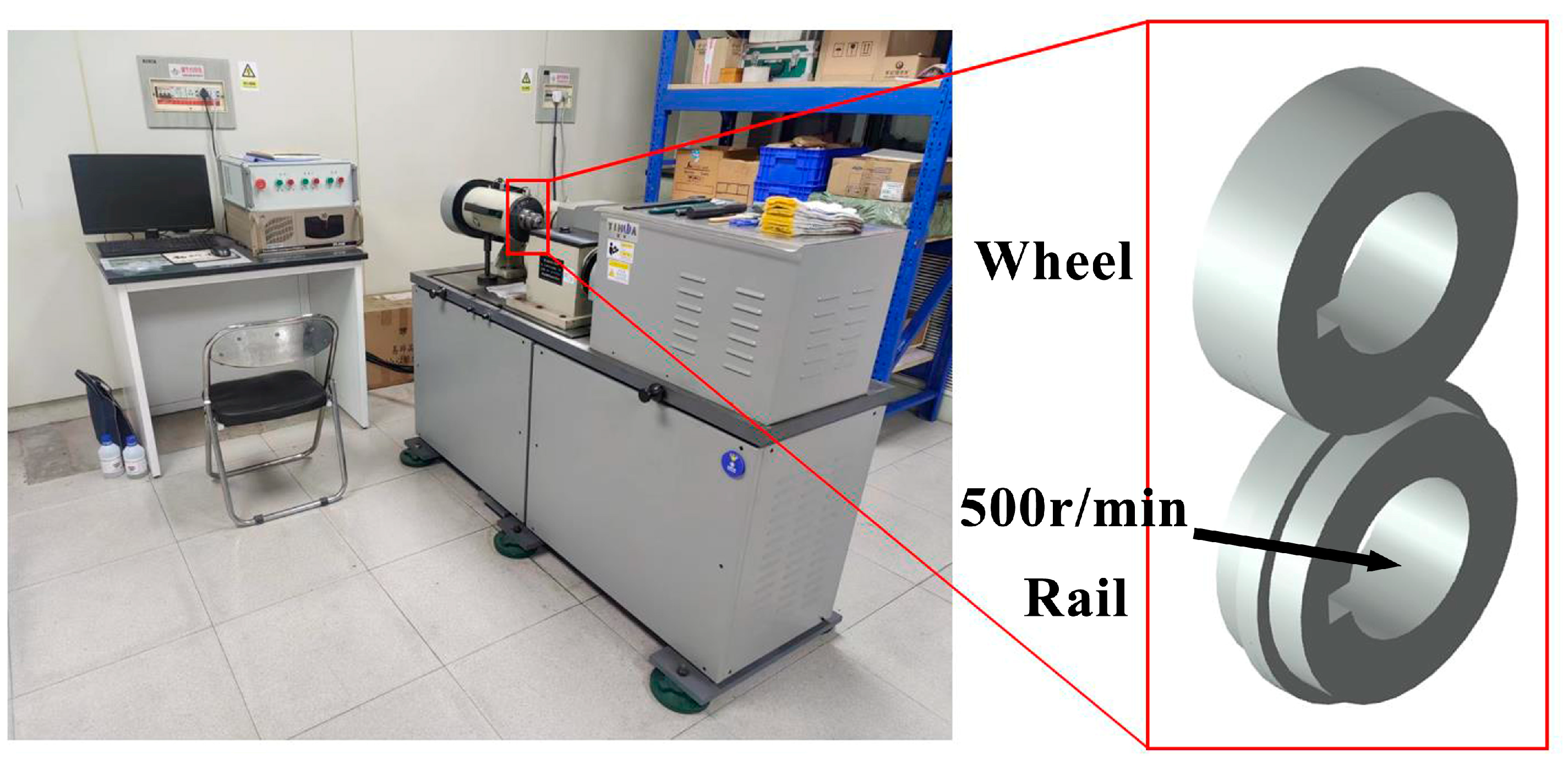
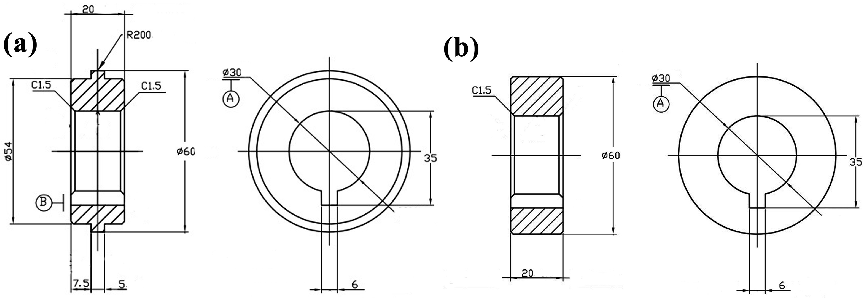
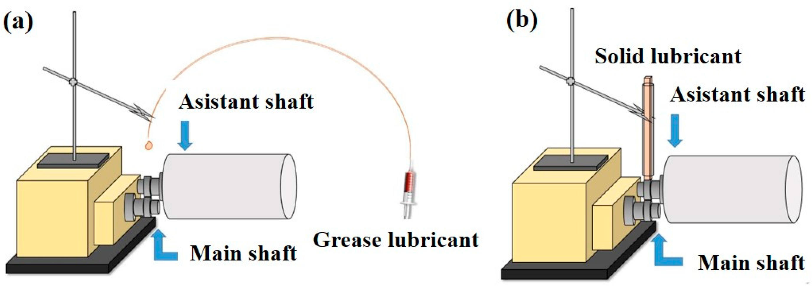
2. Materials and Methods
3. Results and Discussion
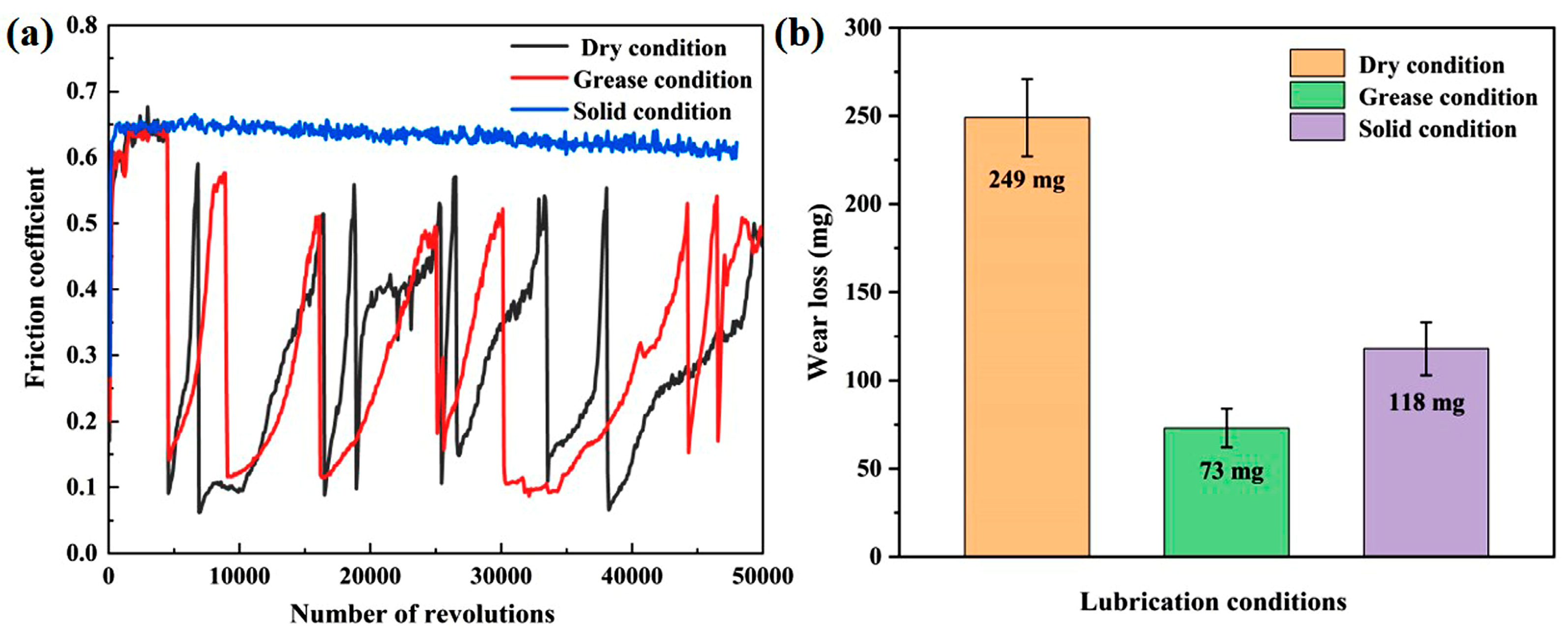
3.1. Wear Loss
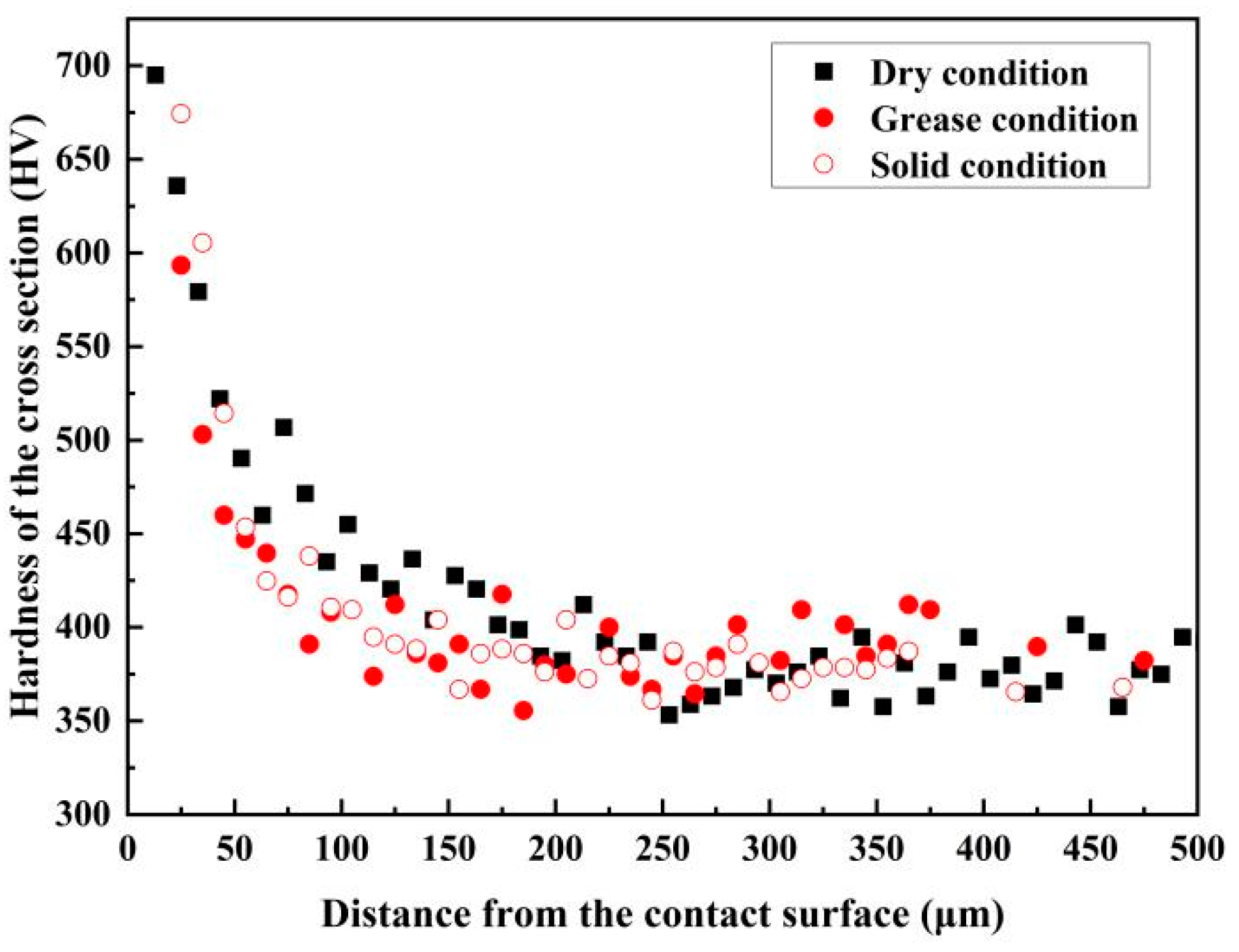
3.2. Hardness
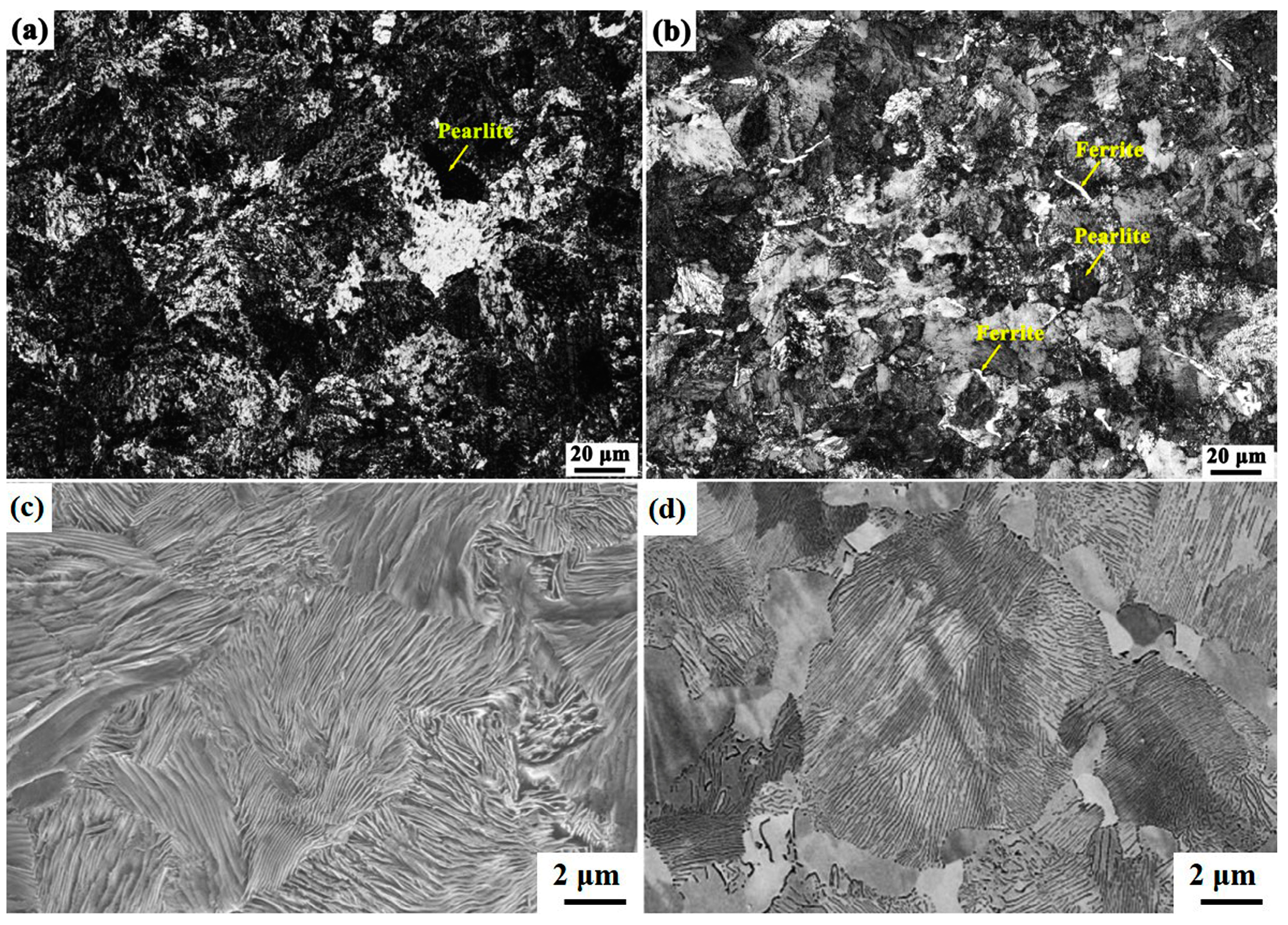
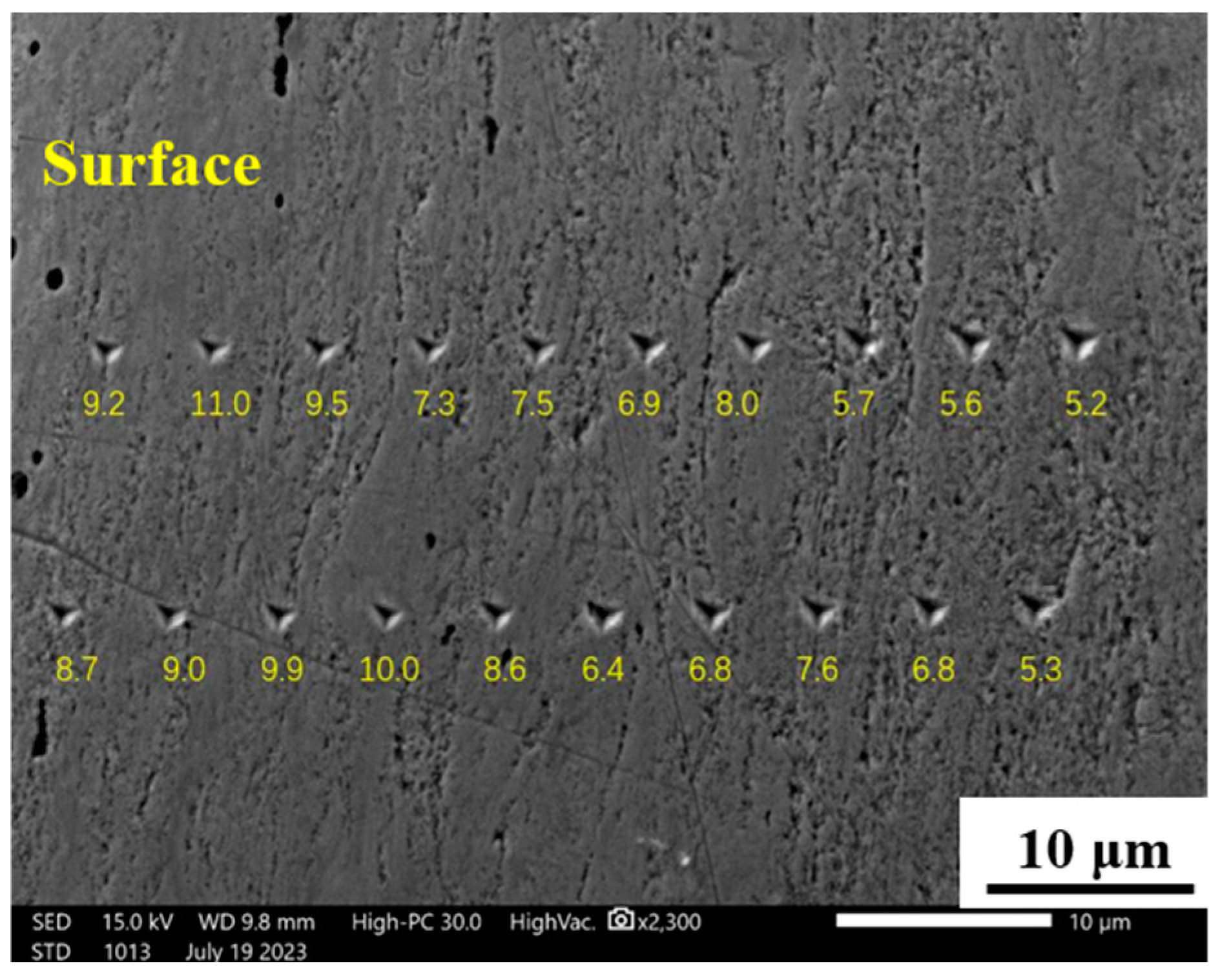
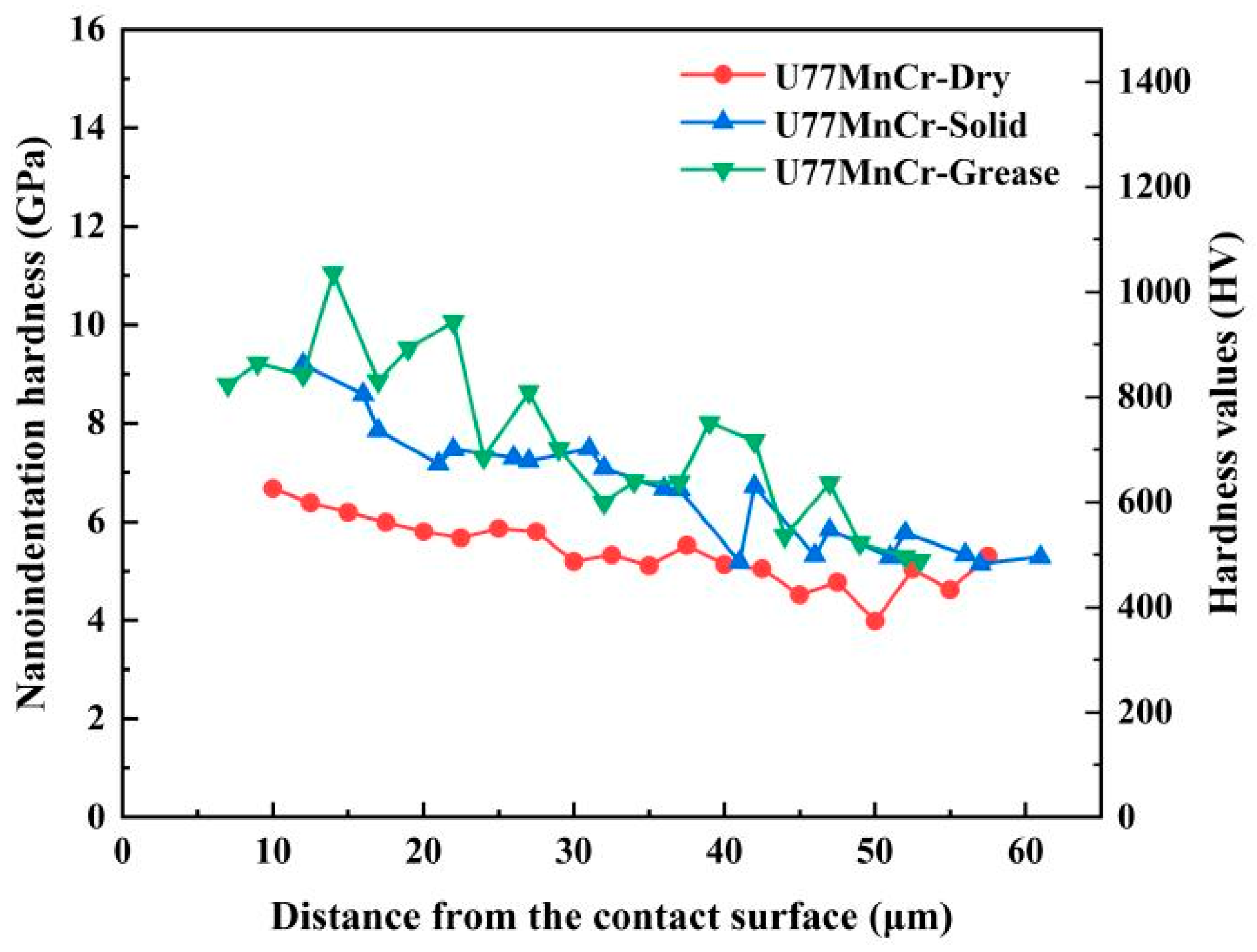
3.3. Microstructure
4. Conclusions
- (1)
- Both grease and solid lubricants played an important role in reducing wear loss. Under the current experimental conditions, the rates of wear loss of U77MnCrH were reduced by 71% for grease lubrication and 55% for solid lubrication, compared with that under the dry condition.
- (2)
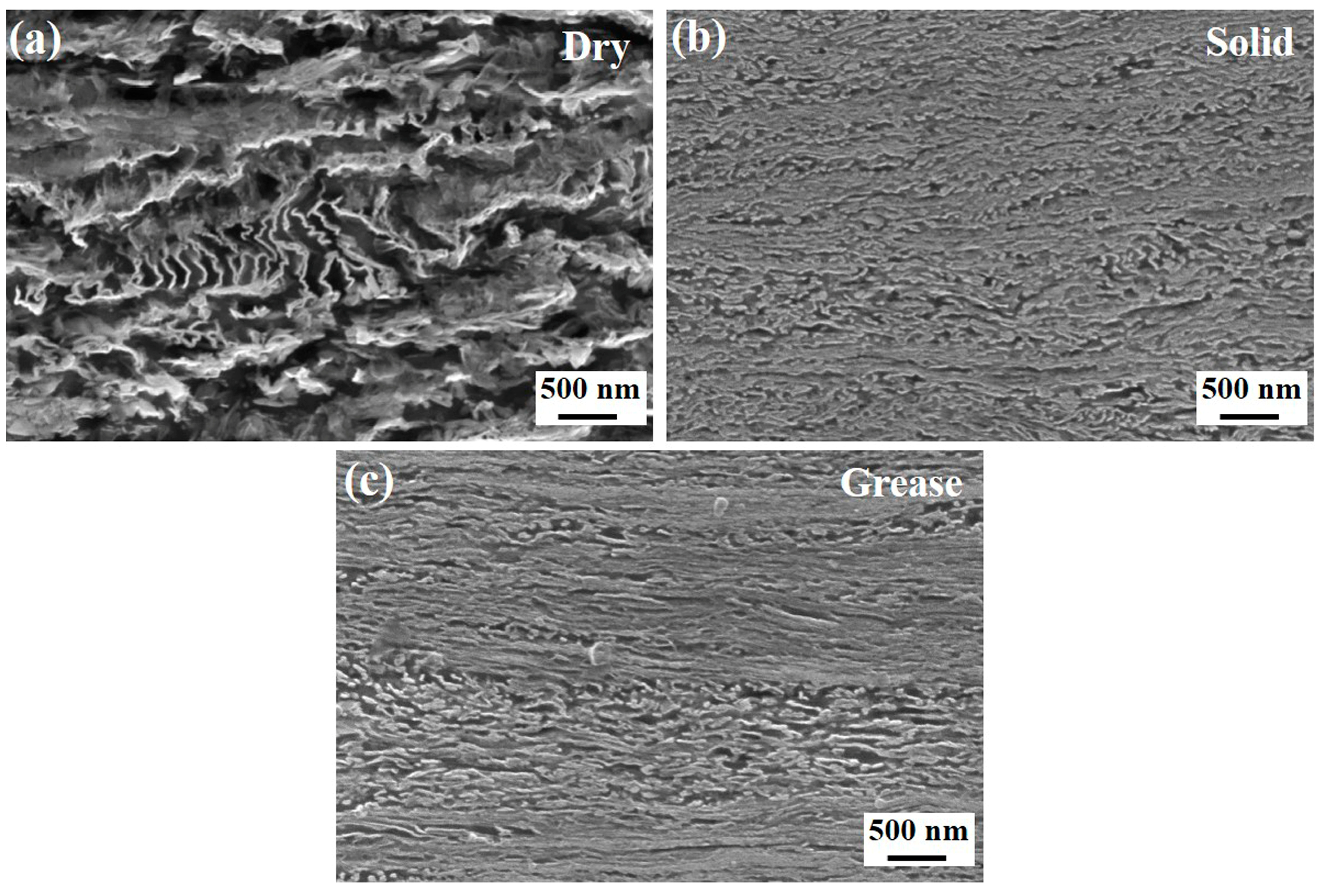
- The thickness of plastic deformation layer of rail was measured to be 167 μm for the dry state, 138 μm for the solid lubrication state, and 128 μm for the oil lubrication state, respectively. The thickness of the plastic deformation layer was largest under dry lubricating conditions.
- (3)
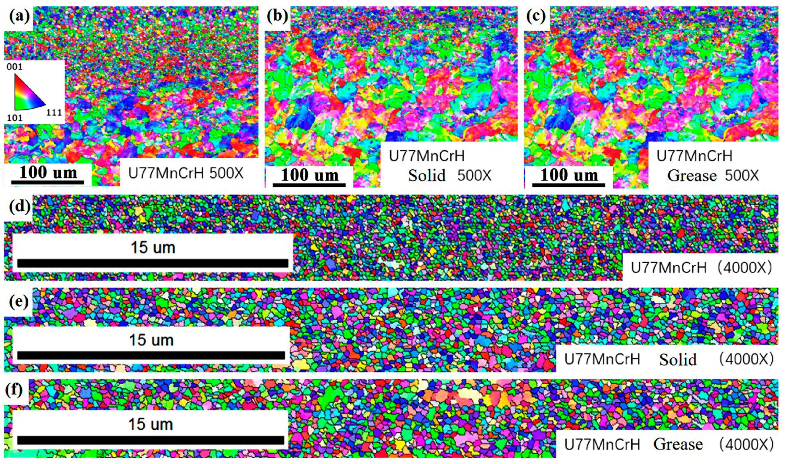
- The microstructure of the deformation layer was coarser and denser under the two lubricated states compared to that under the dry condition. The lubricants types had little effect on average grain sizes.
Author Contributions
Funding
Data Availability Statement
Conflicts of Interest
References
- Cao, Y.; An, Y.T.; Su, S.; Guo, X.; Sun, Y.K. A statistical study of railway safety in China and Japan 1990–2020. Accid. Anal. Prev. 2022, 175, 106674. [Google Scholar] [CrossRef]
- Zhang, S.Y.; Spiryagin, M.; Lin, Q.; Ding, H.H.; Wu, Q.; Guo, J.; Liu, Q.Y.; Wang, W.J. Study on wear and rolling contact fatigue behaviors of defective rail under different slip ratio and contact stress conditions. Tribol. Int. 2020, 169, 107491. [Google Scholar] [CrossRef]
- Zhang, S.Y.; Spiryagin, M.; Ding, H.H.; Wu, Q.; Guo, J.; Liu, Q.Y.; Wang, W.J. Rail rolling contact fatigue formation and evolution with surface defects. Int. J. Fatigue 2020, 158, 106762. [Google Scholar] [CrossRef]
- Hu, Y.; Watson, M.; Maiorino, M.; Zhou, L.; Wang, W.J.; Ding, H.H.; Lewis, R.; Meli, E.; Rindi, A.; Liu, Q.Y.; et al. Experimental study on wear properties of wheel and rail materials with different hardness values. Wear 2021, 477, 203831. [Google Scholar] [CrossRef]
- Wang, Z.Q.; Lei, Z.Y. Analysis of influence factors of rail corrugation in small radius curve track. Mater. Sci. 2021, 12, 31–40. [Google Scholar] [CrossRef]
- Zhu, Y.; Wang, W.J.; Lewis, R.; Yan, W.Y.; Lewis, S.R.; Ding, H.H. A review on wear between railway wheels and rails under environmental conditions. J. Tribol. 2019, 141, 120801. [Google Scholar] [CrossRef]
- Ding, H.H.; Mu, X.P.; Zhu, Y.; Yang, W.B.; Xiao, Q.; Wang, W.J.; Liu, Q.Y.; Guo, J.; Zhou, Z.G. Effect of laser claddings of Fe-based alloy powder with different concentrations of WS2 on the mechanical and tribological properties of railway wheel. Wear 2022, 488–489, 204174. [Google Scholar] [CrossRef]
- Kvarda, D.; Skurka, S.; Galas, R.; Omasta, M.; Shi, L.B.; Ding, H.H.; Wang, W.J.; Krupka, I.; Hartl, M. The effect of top of rail lubricant composition on adhesion and rheological behaviour. Eng. Sci. Technol. 2022, 35, 101100. [Google Scholar] [CrossRef]
- Shebani, A.; Iwnicki, S. Prediction of wheel and rail wear under different contact conditions using artificial neural networks. Wear 2018, 406–407, 173–184. [Google Scholar] [CrossRef]
- Tomeoka, M.; Kabe, N.; Tanimoto, M.; Miyauchi, E.; Nakata, M. Friction control between wheel and rail by means of on-board lubrication. Wear 2022, 253, 124–129. [Google Scholar] [CrossRef]
- Allmaier, H. Increase service life for rail wheel bearings—A review of grease lubrication for this application. Lubricants 2022, 10, 36. [Google Scholar] [CrossRef]
- Kvarda, D.; Galas, R.; Omasta, M.; Shi, L.B.; Ding, H.H.; Wang, W.J.; Krupka, I.; Hartl, M. Asperity-based model for prediction of traction in water-contaminated wheel-rail contact. Tribol. Int. 2021, 157, 106900. [Google Scholar] [CrossRef]
- Stock, R.; Stanlake, L.; Hardwick, C.; Yu, M.; Eadie, D.; Lewis, R. Material concepts for top of rail friction management-classification, characterization and application. Wear 2016, 366–367, 225–232. [Google Scholar] [CrossRef]
- Aldajah, S.; Ajayi, O.O.; Fenske, G.R.; Kumar, S. Investigation of top of rail lubrication and laser glazing for improved railroad energy efficiency. J. Tribol. 2003, 125, 643–648. [Google Scholar] [CrossRef]
- Zhao, X.J.; Chen, Q.; Liu, Y.S.; Qiu, X.Y.; Meli, E.; Rindi, A. Effects of slip ratio and contact stress on rolling contact fatigue of defected rail materials. Eng. Fail. Anal. 2022, 131, 105817. [Google Scholar] [CrossRef]
- Żuchowski, R.; Nowoświat, A.; Kucharski, I. Reduction of tram noise by using a rail lubrication device. Appl. Acoust. 2023, 210, 109429. [Google Scholar] [CrossRef]
- Knothe, K. History of wheel/rail contact mechanics: From Redtenbacher to Kalker. Veh. Syst. Dyn. 2008, 46, 9–26. [Google Scholar] [CrossRef]
- Lewis, R.; Magel, E.; Wang, W.J.; Olofsson, U.; Lewis, S.; Slatter, T.; Beagles, A. Towards a standard approach for the wear testing of wheel and rail materials. Proc. Inst. Mech. Eng. Part F J. Rail Rapid Transit 2017, 231, 760–774. [Google Scholar] [CrossRef]
- Li, Q.; Wu, B.N.; Ding, H.H.; Galas, R.; Kvarda, D.; Liu, Q.Y.; Zhou, Z.R.; Omasta, M.; Wang, W.J. Numerical prediction on the effect of friction modifiers on adhesion behaviours in the wheel-rail starved EHL contact. Tribol. Int. 2022, 170, 107519. [Google Scholar] [CrossRef]
- Galas, R.; Kvarda, D.; Omasta, M.; Krupka, I.; Hartl, M. The role of constituents contained in water-based friction modifiers for top-of-rail application. Tribol. Int. 2017, 117, 87–97. [Google Scholar] [CrossRef]
- Messaadi, M.; Oomen, M.; Kumar, A. Friction modifiers effects on tribological behaviour of bainitic rail steels. Tribol. Int. 2019, 140, 105857. [Google Scholar] [CrossRef]
- Li, J.X.; Wu, B.N.; Ding, H.H.; Galas, R.; Omasta, M.; Wen, Z.F.; Guo, J.; Wang, W.J. Wear and damage behaviours of wheel and rail materials: Effects of friction modifier and environmental temperature. Wear 2023, 523, 204796. [Google Scholar] [CrossRef]
- Biazon, L.; Ferrer, B.P.; Toro, A.; Cousseau, T. Correlations between rail grease formulation and friction, wear and RCF of a wheel/rail tribological pair. Tribol. Int. 2021, 153, 106566. [Google Scholar] [CrossRef]
- Huang, Y.B.; Shi, L.B.; Zhao, X.J.; Cai, Z.B.; Liu, Q.Y.; Wang, W.J. On the formation and damage mechanism of rolling contact fatigue surface cracks of wheel/rail under the dry condition. Wear 2018, 400–401, 62–73. [Google Scholar] [CrossRef]
- Molyneux-Berry, P.; Davis, C.; Bevan, A. The influence of wheel/rail contact conditions on the microstructure and hardness of railway wheels. Sci. World J. 2014, 2014, 209752. [Google Scholar] [CrossRef] [PubMed]
- Kim, W.; Lee, K.; Kim, J.-H.; Kim, Y.-C.; Kwon, D. A further study on knoop indentation plastic deformation for evaluating residual stress. Korean J. Met. Mater. 2020, 58, 515–521. [Google Scholar] [CrossRef]
- Li, N.; Kingkam, W.; Han, R.H.; Tang, M.; Zhang, H.X.; Zhao, C.Z. Effect of dynamic recrystallization on the transformed ferrite microstructures in HSLA steel. Metals 2020, 10, 817. [Google Scholar] [CrossRef]
- Elwazri, A.M.; Wanjara, P.; Yue, S. Dynamic recrystallization of austenite in microalloyed high carbon steels. Mater. Sci. Eng. A 2019, 339, 209–215. [Google Scholar] [CrossRef]
- Cottrell, A. Dynamical recovery. J. Mater. Sci. 2004, 39, 3865–3870. [Google Scholar] [CrossRef]
- Tian, J.Y.; Wang, H.X.; Zhu, M.; Zhou, M.X.; Zhang, Q.; Su, X.; Guo, A.M.; Xu, G. Improving mechanical properties in high-carbon pearlitic steels by replacing partial V with Nb. Mater. Sci. Eng. A 2022, 834, 142622. [Google Scholar] [CrossRef]
- Tian, J.Y.; Xu, G.; Hu, H.J.; Wang, X.; Zurob, H. Transformation kinetics of carbide-free bainitic steels during isothermal holding above and below MS. J. Mater. Res. Technol. 2020, 9, 13594–13606. [Google Scholar] [CrossRef]
- Zhang, X.D.; Hansen, N.; Gao, Y.K.; Huang, X.X. Hall-Petch and dislocation strengthening in graded nanostructured steel. Acta Mater. 2012, 60, 5933–5943. [Google Scholar] [CrossRef]
- Uchima, H.; Kumagai, M.; Shimbe, J.; Tanabe, A.; Mizuno, Y.; Onuki, Y. Impact of dislocation density and mobility on yielding behavior in quenched medium-carbon martensitic steel tempered at low temperature. ISIJ Int. 2022, 62, 998–1003. [Google Scholar] [CrossRef]


| Steels | C | Mn | Si | Ni | Cr | Cu | Mo | V |
|---|---|---|---|---|---|---|---|---|
| U77MnCrH | 0.786 | 0.958 | 0.450 | 0.076 | 0.370 | 0.099 | 0.0006 | -- |
| CL65 | 0.632 | 0.781 | 0.651 | 0.010 | 0.090 | 0.010 | 0.002 | 0.020 |
| Steels | Tensile Strength (MPa) | Yield Strength (MPa) | Elongation (%) | Reduction in Area (%) | Surface Hardness (HBW) |
|---|---|---|---|---|---|
| U77MnCrH | 1262 | 718 | 13.25 | 40 | 371 |
| CL65 | 1077 | 697 | 15.50 | 41 | 333 |
| Rail | Contact Stress | Interface Status | Vertical Force | Wheel | Slip | Number of Revolutions | Speed of Main Shaft |
|---|---|---|---|---|---|---|---|
| U77MnCrH | 1200 MPa | Dry Grease Solid | 1400 N | CL65 | 4% | 50,000 | 500 r/min |
| Lubrication Condition | Number of Grains | Average Grain Size (μm) |
|---|---|---|
| Dry | 7196 ± 27 | 0.22 ± 0.03 |
| Solid | 3650 ± 31 | 0.32 ± 0.04 |
| Grease | 3770 ± 16 | 0.33 ± 0.02 |
Disclaimer/Publisher’s Note: The statements, opinions and data contained in all publications are solely those of the individual author(s) and contributor(s) and not of MDPI and/or the editor(s). MDPI and/or the editor(s) disclaim responsibility for any injury to people or property resulting from any ideas, methods, instructions or products referred to in the content. |
© 2024 by the authors. Licensee MDPI, Basel, Switzerland. This article is an open access article distributed under the terms and conditions of the Creative Commons Attribution (CC BY) license (https://creativecommons.org/licenses/by/4.0/).
Share and Cite
Liang, X.; Wei, X.; Li, Y.; Wang, M.; Liu, F. Effects of Lubricating Conditions on Wear Performance of U77MnCrH Rail. Metals 2024, 14, 414. https://doi.org/10.3390/met14040414
Liang X, Wei X, Li Y, Wang M, Liu F. Effects of Lubricating Conditions on Wear Performance of U77MnCrH Rail. Metals. 2024; 14(4):414. https://doi.org/10.3390/met14040414
Chicago/Turabian StyleLiang, Xu, Xikai Wei, Yingqi Li, Meng Wang, and Fengshou Liu. 2024. "Effects of Lubricating Conditions on Wear Performance of U77MnCrH Rail" Metals 14, no. 4: 414. https://doi.org/10.3390/met14040414
APA StyleLiang, X., Wei, X., Li, Y., Wang, M., & Liu, F. (2024). Effects of Lubricating Conditions on Wear Performance of U77MnCrH Rail. Metals, 14(4), 414. https://doi.org/10.3390/met14040414