
Mechanical Properties of Interfaces between Mg and SiC: An Ab Initio Study

1
Institute of Materials Simulation, Friedrich-Alexander-Universität Erlangen-Nürnberg (FAU), Dr.-Mack-Str. 77, 90762 Fürth, Germany
2
School of New Energy and Materials, Southwest Petroleum University, Chengdu 610500, China
*
Author to whom correspondence should be addressed.
Metals 2024, 14(4), 467; https://doi.org/10.3390/met14040467
Submission received: 21 February 2024
/
Revised: 10 April 2024
/
Accepted: 15 April 2024
/
Published: 16 April 2024
(This article belongs to the Special Issue Multi-Scale Simulation of Metals and Alloys)
Abstract
:Covalently bonded particles may exhibit extremely high strength, but their performance in the reinforcement of metal alloys crucially depends on the properties of their interfaces with the embedding matrix. Here, density functional theory is used for investigating a range of interface configurations between magnesium and silicon carbide in view of their mechanical properties. Interfaces are analyzed not only in terms of interface energy/work of separation but also in terms of the interfacial shear stresses required to induce interface-parallel displacements. These properties are studied for bilayer systems with different orientations of the Mg and SiC layers and for different terminations of the SiC layer (Si or C atoms located at the interface). The results are discussed in terms of their implication for mechanical behavior of SiC reinforced Mg alloys.
1. Introduction
Magnesium is a lightweight metal with excellent strength-to-weight ratio. Thus, it has vast potential applications for improving fuel economy by reducing the weight of engineering components. However, its application is currently hindered by comparatively low creep resistance and moderate ductility, resulting from its hexagonal lattice structure. Ferkel and Mordike [1] demonstrated a significant improvement in creep properties by added SiC nanoparticles, and subsequent research confirmed that SiC nanoparticle reinforcement can substantially improve the creep [2,3] and wear [4] properties of Mg alloys. For an overview, see the review by Dey and Pandey [5]. At the same time, it has been observed that SiC nanoparticle reinforcement may lead to a deterioration in tensile properties such as failure strain and ultimate tensile strength [6], or a pronounced trade-off between enhanced strength and reduced ductility is observed. Scanning electron microscopy observations on SiC-nanoparticle-reinforced Mg indicated that failure may initiate by nucleation of voids at or near Mg–SiC interfaces [7,8], with void coalescence and macrocrack formation as subsequent stages of the failure process. Thus, a thorough investigation of the properties of Mg–SiC interfaces is mandatory for understanding the deformation and failure mechanisms in Mg–SiC nanocomposites. A quantitative understanding of interface properties is particularly important for attempts to overcome the strength–ductility dilemma in Mg–SiC nanocomposites by means of hierarchically architectured microstructures, as proposed recently by Luo and coworkers [7,8,9]. Quantitative interface data are, in particular, indispensable for parameterizing molecular dynamics [10] or crystal plasticity simulations.
In the present investigation, we used density functional theory calculations to explore the mechanical properties of Mg–SiC interfaces. Similar investigations have been carried out by other authors for a range of interfaces between metals and covalent nanoparticles. In particular, recent studies of Fathalian et al. [11] investigated interfaces between Al and SiC, and Nasiri et al. [12,13] investigated the mechanical properties of the interfaces between Al and graphene as well as Pt and graphene.
In our characterization of mechanical interface properties, we considered energy changes under interface-perpendicular (tension/compression) as well as interface-parallel (shear) displacements, to establish key mechanical parameters like interface energy and tensile and shear strength. Investigated interface models and simulation methodology are presented in Section 2, while results are discussed in Section 3. Conclusions and a brief outlook are provided in Section 4.
2. Materials and Methods
2.1. Interface Models
Our interface models consisted of bilayers of silicon carbide and magnesium, where each layer represented a planar slab of finite height. Periodic boundary conditions were imposed parallel to the bilayer direction. The silicon carbide slabs were labeled according to their termination (the type of atoms next to the Mg slab); thus, “SiC” denotes a Si-terminated silicon carbide slab, whereas “CSi” denotes a C-terminated slab. Next, the slabs were labeled by the crystallographic orientation of the slab normal vectors. Thus, “SiC(111)Mg(0001)” denotes a configuration where the bilayer is oriented perpendicular to the z axis of the hexagonal Mg lattice such that the interface plane is parallel to the Mg basal plane and to a (111) plane of the 3C-SiC lattice. For Si, the hexagonal 2H polytype with layer orientation (0001) was considered alongside the cubic 3C polytype with orientation (111). For Mg, slabs of orientation (0001) and (100) were considered.
Our investigation focused on coherent interfaces. Figure 1 shows the supercells of three configurations, namely, CSi(0001)Mg(0001), CSi(111)Mg(0001), and CSi(111)Mg(100). Note that the corresponding Si-terminated configurations can be simply obtained by swapping the Si and C atoms.
The x, y, and z directions are aligned with the three sides of the prismatic supercell and do not, in general, constitute a Cartesian coordinate system. The blue circles represent Si atoms, brown circles represent C atoms, and green circles represent Mg atoms. The black-lined boxes are the supercells used in the calculations. The lengths of the supercell in the x and y directions are indicated in the figure, whereas the length in z direction was set to 55 Å for all configurations, creating a vacuum gap of approximately 25 Å. Because the crystallographic unit cells of Mg and SiC do not match perfectly, the Mg and SiC slabs are slightly strained (Mg in biaxial compression, SiC in biaxial tension). The interface-parallel dimensions of the supercell as given in Figure 1 were chosen such as to minimize the overall energy; during deformation, these dimensions were kept fixed. Note that the unit cell sizes in Figure 1 do not represent intrinsic properties of the interfaces: if one increases the ratio of Mg slab thickness to SiC slab thickness, the supercell size that minimizes the misfit strain energy increases; if one decreases that ratio, it decreases.
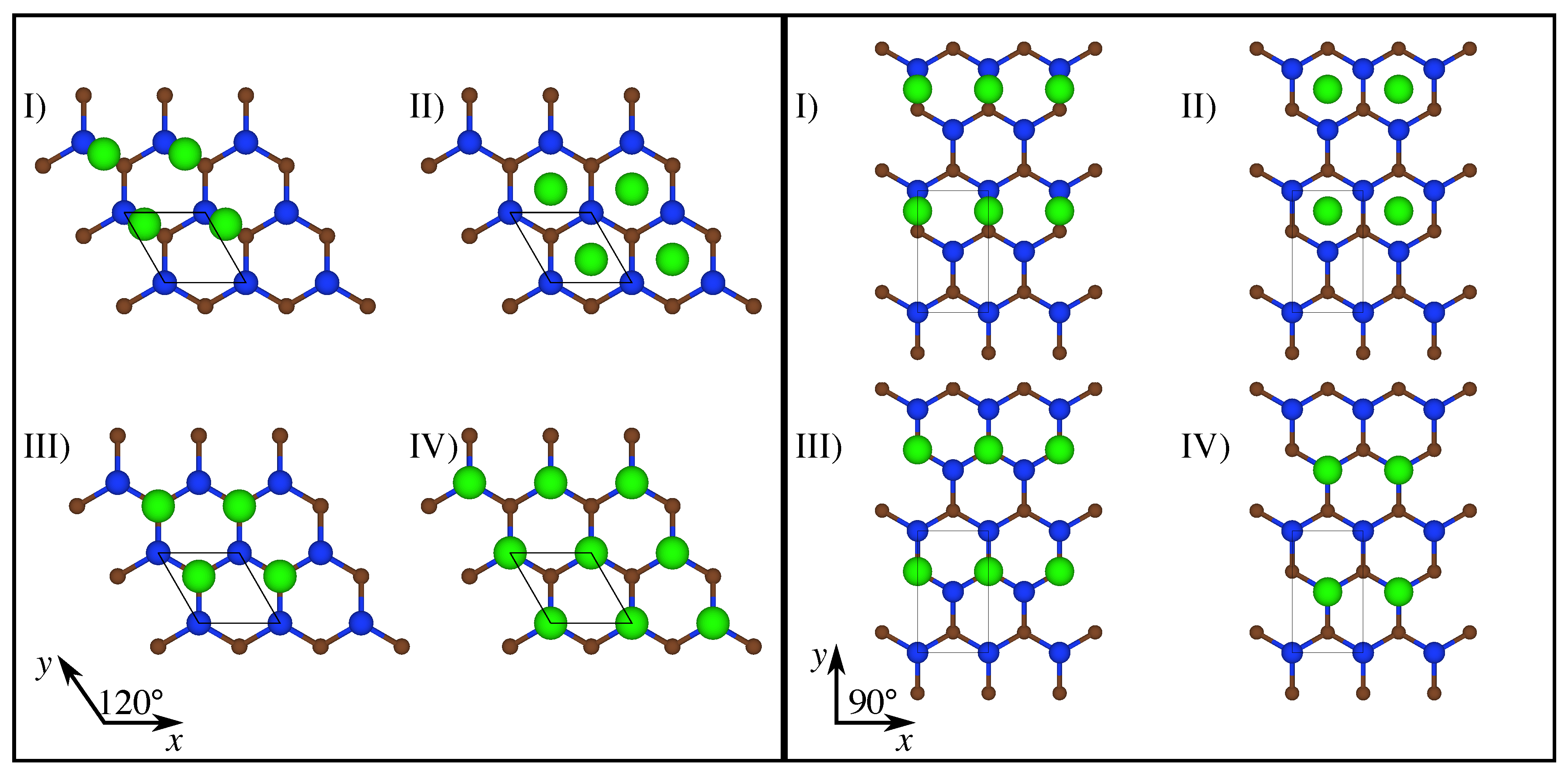
To map out the interface energy ‘landscape’, we considered energy profiles both perpendicular and parallel to the plane of the bilayer for each interface model. Interface-perpendicular energy profiles were obtained by constraining the Mg and Si/C atoms in the planes adjacent to the interface to maintain a prescribed distance, which was then increased. Four different high-symmetry configurations of the Mg relative to the Si/C plane were considered, as shown in Figure 2, left, for SiC(111)Mg(0001) and in Figure 2, right, for SiC(111)Mg(100). For simplicity, only the atoms in the lattice planes directly adjacent to the interface are shown in the figure. C-terminated configurations were obtained by swapping Si and C atoms; SiC(0001) is not shown separately since the arrangement of the atoms in the terminating plane is identical to SiC(111).
The four interface configurations labeled (I) to (IV) in Figure 2, left and right, are, respectively, denoted as “bridge”, “hollow”, “top-C”, and “top-Si”.
In addition, to compare the mechanical properties of pure Mg and SiC-reinforced Mg, we duplicated the Mg slab of CSi(111)Mg(0001) and CSi(111)Mg(100) and set an imaginary interface in the middle to perform, in the Mg–Mg model the same separation calculation as in the SiC–Mg model.
2.2. DFT Calculation Settings
All calculations were carried out using the Quantum Espresso package version 6.8 [14,15,16], using the pseudopotentials of the standard solid-state pseudopotentials library optimized for precision (SSSP Precision version 1.1.2) [17,18]. Exploratory calculations were performed with eight different exchange-correlation functionals, and it was decided to use the vdw-DF-obk8 exchange-correlation functional in this study. This functional was shown to give a reasonably accurate prediction of interlayer distances and binding energies for both SiC and Mg. It can accurately describe intermolecular interactions with mean absolute errors on the order of 9% [19,20]. In addition, this exchange-correlation functional produces cohesive energies that are near the median of those obtained from all explored functionals, thus avoiding systematic over- or underestimation of the total energy.
In our calculations, after preliminary convergence tests, the kinetic energy cutoffs were set to 45 Ry and 450 Ry for the wave function and charge density calculations, respectively, and a Gaussian smearing of 0.005 Ry was used for Brillouin zone integration. The convergence threshold for self-consistency calculations was less than Ry. A 6 × 6 × 1 k-points grid was used in the calculations of all configurations. All DFT parameters were varied and tested for convergence; see data in the Supplemental Material.
From the calculated energies of the SiC slabs, the Mg slabs, and the SiC-Mg bilayers obtained by putting the SiC and Mg slabs into contact, we evaluated the interface energies as
Here, is the total energy of the SiC–Mg bilayer, represents the energy of the SiC slab, and represents the energy of the Mg slab. These slab energies were evaluated using the same lateral dimensions of the supercell as for the bilayer (in practice, we simply separate both slabs to a distance of half the vacuum gap); hence, elastic energy contributions that arose as the slabs were strained to match the lattice constants and enable a coherent interface were not counted as part of the interface energy. A is the area of the supercell in the plane.
2.3. Deformation Protocol
For analyzing deformation on the atomic scale, an initial deformation must be imposed on the supercell, followed by constrained relaxation to obtain energy data that relate the net energy change to the imposed deformation. Depending on the nature of the initial deformation and the degrees of freedom allowed to relax, a variety of protocols are possible. We first considered the case of shear deformation, which has been extensively studied in the context of determining generalized stacking fault energy (GSFE) surfaces in bulk metals and served as a template for our own work on interface energy surfaces (IES) reported in Section 3.2. In the context of Mg, GSFE surfaces have been studied, e.g., by Muzyk et al. [21] and Shang et al. [22]. We followed the terminology used in these papers. Three fundamental modes of shear are distinguished: (i) In affine shear mode, the entire supercell is subjected to an affine shear deformation, where the shearing direction is parallel to the investigated shear plane (in our case, the Mg–Si interface plane; for the corresponding bulk Mg samples, a (0001) or (1010) Mg lattice plane). (ii) Alias shear applies the shear displacement only to a single layer of atoms, typically the uppermost layer of the sample; the shear then spreads over the sample during relaxation. (iii) Slab shear divides the sample into two parallel slabs and localizes the imposed shear displacement at the interface between them.
After initial deformation, constrained relaxation was carried out, which allowed the atom positions to adjust while maintaining either the overall shear (affine shear) or the displacement on the alias plane (alias shear). In case of slab shear, relaxation is typically allowed only in the direction perpendicular to the shearing plane.
In our preliminary studies, we used SiC(111)Mg(0001) samples to probe their behavior under alias shear and slab shear protocols (note that imposing affine shear makes little sense for a bilayer consisting of two materials with significantly different elastic moduli). This led us to the conclusion that alias shear was not useful for our purposes. The reason is that alias shear allows, during relaxation, deformation to spread across the sample and to localize on the plane that can accommodate the largest shear at the lowest energy cost. Because the Mg–SiC interface shows a stiffer shear response than the basal plane of bulk Mg, this has the consequence of the ultimate shear instability always occurring between two Mg(0001) planes within the Mg layer. We were effectively probing the properties of bulk Mg under (0001) shear and not the properties of the SiC–Mg interface. Only for slab shear, by construction, does shear deformation remain localized on the interface plane. This allowed us, by comparing data obtained for slab shear on the interface with data obtained for slab shear between two Mg(0001) slabs, to perform a ’fair’ comparison between Mg(0001) bulk shear properties and SiC(111)Mg(0001) interface shear properties. Similar considerations applied to the other configurations investigated in this study.
Turning to tensile loading, as studied in Section 3.1, similar considerations apply. The analog of alias shear is applying a tensile displacement to the uppermost layer of Mg and increasing the same in small steps, each step followed by relaxation. We tried this as well, again for SiC(111)Mg(0001), with similar consequences as in shear deformation: the Mg–Mg planes have significantly lower cleavage stress than the Mg–SiC interface. As a consequence, failure always occurs between two Mg planes. We used the same remedy as in shear: we applied a tensile displacement not to the uppermost layer but between the termination planes of the SiC and those of the Mg slabs, followed by constrained relaxation similar to the slab protocol in shear. Again, we compared this with the behavior of two Mg layers separated under the same constraints and thus obtained a quantitative comparison.
Both in shear and in tension, the layer-parallel or layer-perpendicular displacements between the SiC and Mg layers were increased in small steps, followed by constrained relaxation. Step sizes are indicated by the data points in the figures showing our results in the next section. After each step, energies per unit area were determined. The derivatives of the energy per unit area with respect to the displacement coordinate were interpreted as tensile stresses (layer-perpendicular displacement) or shear stresses in displacement direction (layer-parallel displacement).
3. Results
3.1. Behavior under Interface-Normal Displacement
3.1.1. Effects of Polytype and Termination
We first investigated how interface energies differ among different SiC polytypes. To this end, we studied different interface configurations between Mg (0001) and 2H-SiC(0001) and 3C-SiC(111) orientations, as described in Section 2.1. The structures were divided into two groups: interfaces with C termination and interfaces with Si termination of the SiC slab. For each group, four interface configurations (bridge, hollow, top-C, and top-Si) were considered.
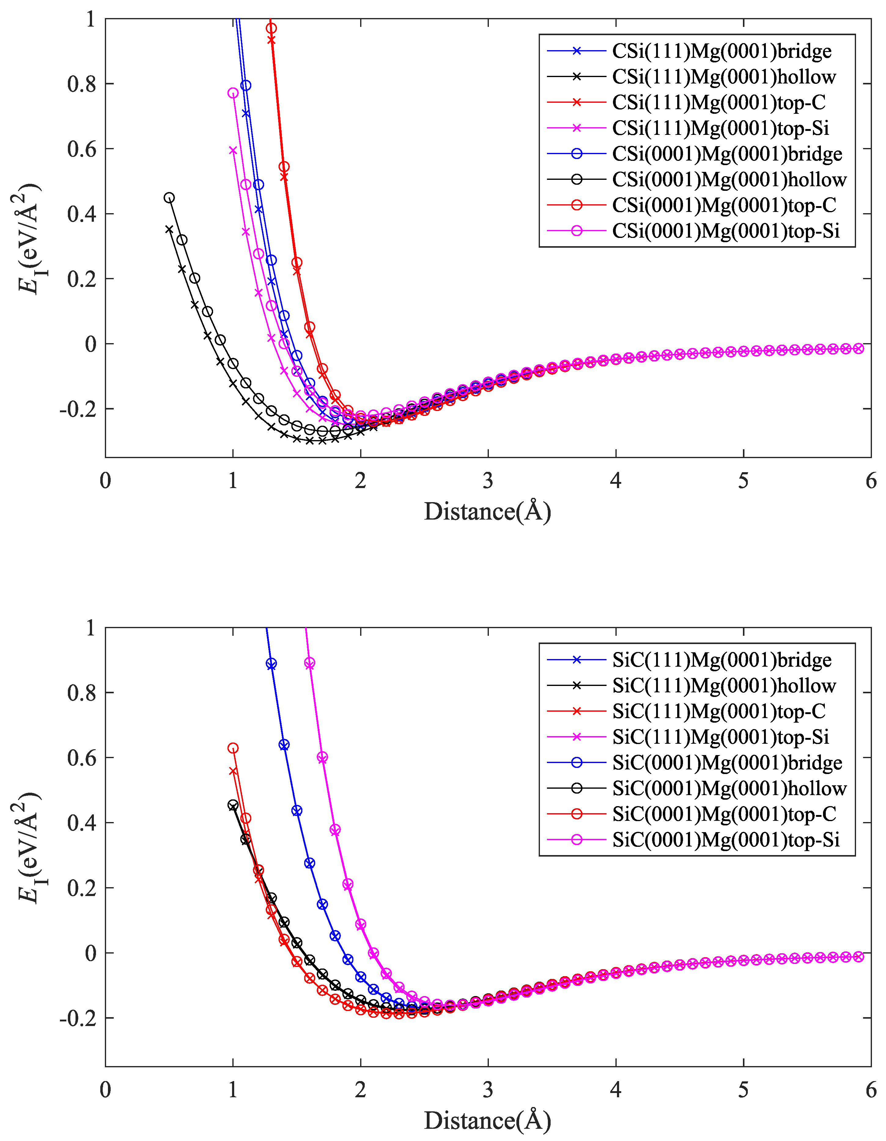
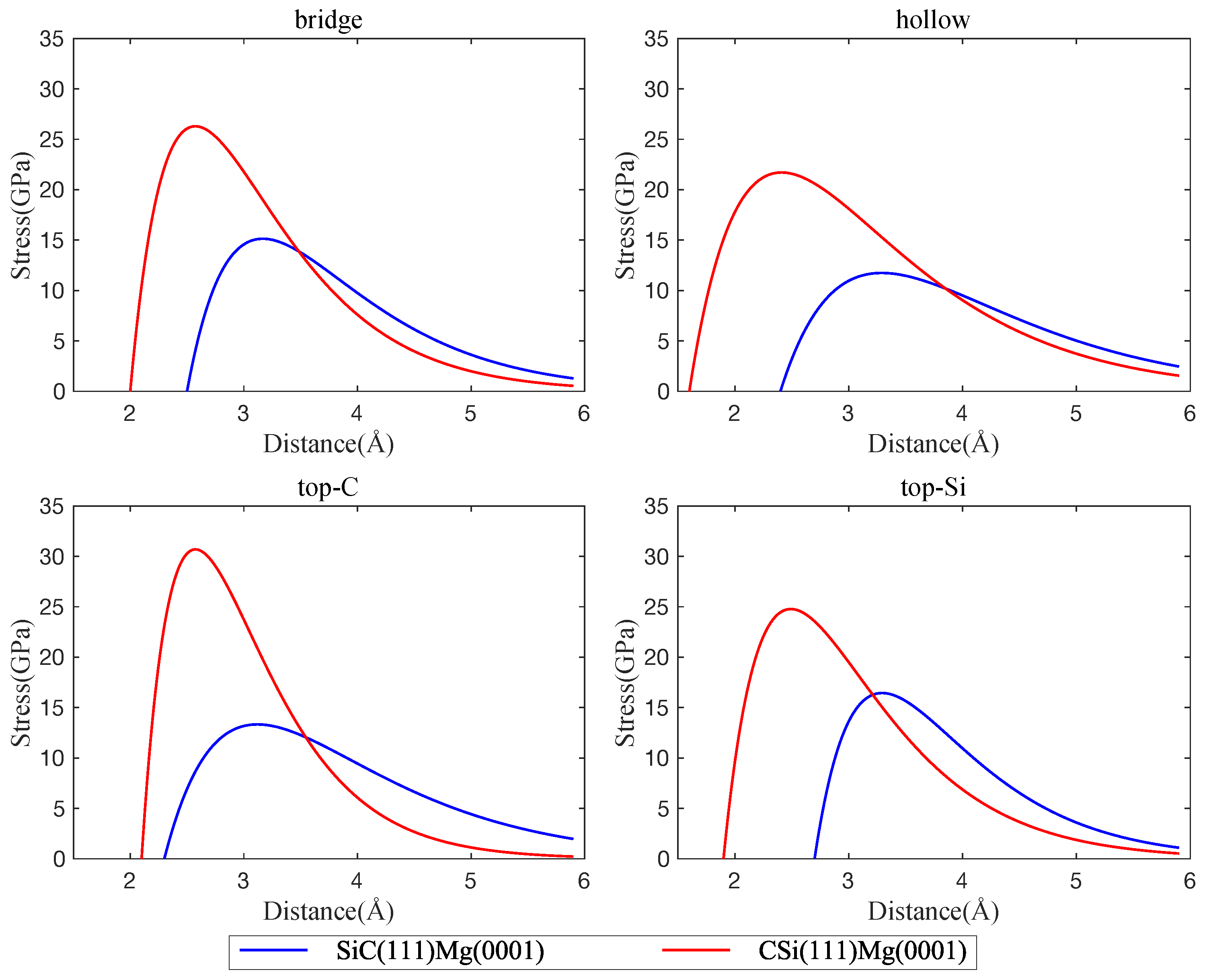
Energy vs. distance curves are shown in Figure 3. It can be seen that there are only minor differences between the interface energies of cubic and hexagonal polytypes of SiC with Mg(0001). This is to be expected, since the atomic configurations at the SiC(0001) and SiC(111) surfaces are very similar. On the other hand, the termination of the SiC slab (C atoms or Si atoms) has a strong effect on both interface strength and interface width. The direct comparison of Figure 4 and Figure 5 shows that interfaces with C-terminated SiC have, in general, lower energy, smaller interface width, and higher separation stress. These observations point to some degree of chemical bonding between Mg and C atoms and indicate that interfaces with C-terminated SiC are both thermodynamically and mechanically more stable than interfaces with Si termination.
We note that our interface energy curves (energy vs. separation distance d) and the corresponding interface tensile stress curves (stress vs. d) can, within the considered range of separation distances, be well represented by simple three-parameter fit curves:
Here, is the (minimum) interface energy, is the location of the energy minimum that defines the interface width, and l is a length scale parameter that controls the steepness of the minimum and hence the interface stress. The full lines in Figure 4, Figure 5, Figure 6 and Figure 7 represent the fits using Equation (2).
3.1.2. Effect of Mg Orientation
To see the effect of the orientation of the Mg slab on the interface energy, we considered two slab orientations, namely, Mg(0001) and Mg(100). Again, interfaces with C termination of the SiC slab consistently show lower energy, smaller interface width, and higher separation stress. Here, we therefore considered only C-terminated interfaces and note that the results carry over to Si-terminated ones, albeit with higher energies and larger interface widths.
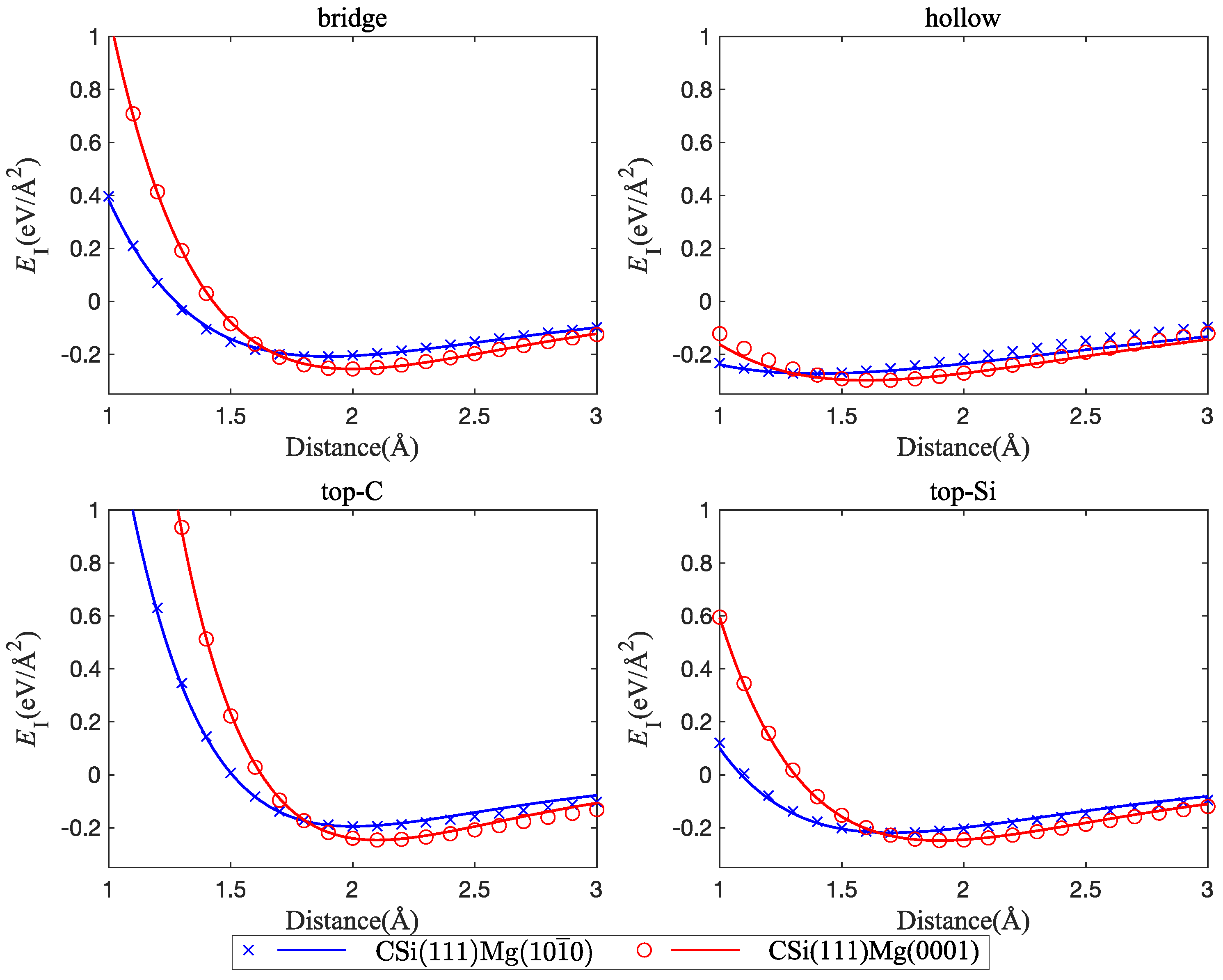
Figure 6 shows that interfaces between CSi(111) and Mg have lower energy for (0001)-oriented than for (100)-oriented Mg slabs, even though the interface width is smaller for the (100) orientation. We applied the same strategy to fit the interface stress curve as outlined in Section 3.1.1. The interface separation stress is higher for the (0001)-oriented Mg slab, and the mechanical behavior in the (0001) orientation is, in general, stiffer (Figure 7). The minimum interface energies of the different structures and the corresponding separation stresses and interface distances between SiC and Mg are compiled in Table 1.
3.2. Interface-Parallel Displacement: Interface Energy Surface and Interface Shear Stress
To analyze the mechanical properties of SiC–Mg interfaces under shear, we used the methodology introduced by Nasiri et al. [12] for studying the properties of Pt adsorbed on graphene. To this end, we determined an ’interface energy surface’ akin to the stacking-fault energy surface commonly studied in investigations of mechanical behavior of metals [23]. This surface is obtained by sliding the Mg layer rigidly on the SiC layer while keeping the distance at the position of the lowest energy. Twenty displacement steps were uniformly distributed along x or y directions to scan the periodic supercell. The resulting interface energy surfaces are shown in Figure 8, and typical profiles of the energy and the energy derivative (the interfacial shear stress) are compiled in Figure 9 and Figure 10.
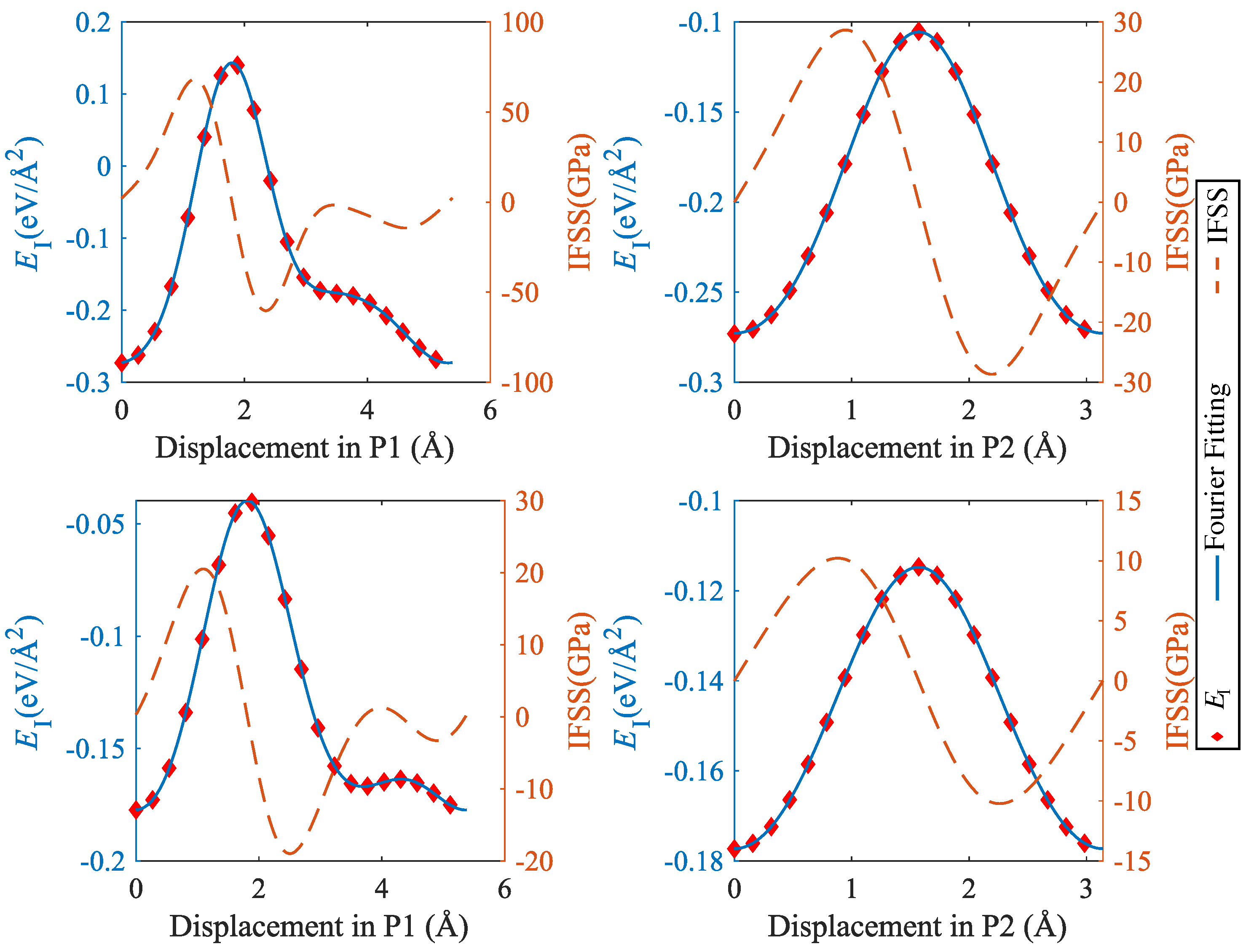
It can be seen that the interface energy variations are strongly anisotropic. For determining linear energy profiles, we considered the directions marked by P1 and P2 in Figure 8, where P1 corresponds to the displacement path with maximum energy variation, whereas P2 represents a displacement path of low energy variation. Results are shown in Figure 9 for CSi(111)Mg(0001) and SiC(111)Mg(0001), and in Figure 10 for CSi(111)MgMg(100) and SiC(111) Mg(100). To obtain interface stress from the interface energy profiles, we fit the interface energy profiles by a 4th order Fourier series for P1-direction and a 2nd order Fourier series for P2-direction and then take the spatial derivative. The resulting IFSS profiles are also shown in Figure 9 and Figure 10.
For both orientations of the Mg layer, the variations in interface energy and IFSS are much more pronounced for the interfaces with C termination of the SiC layer, demonstrating the stronger directional bonding between C and Mg atoms as compared to Si and Mg.
Comparing the two investigated orientations of the Mg layer, we observed that the interfaces with Mg(0001) orientation have smaller energy variations and IFSS values than the interfaces with Mg(100) orientation. This is expected as the close-packed basal plane provides a much better match to the SiC(111) plane than the prismatic (100) plane.
Looking at the absolute values of the interfacial shear stresses in the ’easy’ P2 direction, we observed peak IFSS values of about 23.5 GPa for CSi(111)Mg(0001) and of about 28.7 GPa for CSi (111) Mg (100). For the corresponding Si-terminated interfaces, the peak IFSS values are, respectively, 4.8 GPa and 10.2 GPa lower. Thus, the higher mechanical stability of the C-terminated interface under tensile loads carries over to a higher resistance against shear displacements.
4. Discussion and Conclusions
The aim of this study was to investigate the mechanical properties of SiC–Mg interfaces in view of the behavior of SiC as the particle reinforcement in Mg matrix composites. To this end, we determined interface energies, interface separation stresses, and interfacial shear stresses for a range of interface configurations. In order to assess the implications of our findings, it is important to compare the determined interface energies with the surface energy of bulk Mg. Tang et al. used systematic DFT calculations to investigate Mg surfaces with a wide range of orientations [24]. For example, for a (0001) surface, the separation energy (i.e., twice the surface energy) was found to be about 0.08 eV/Å2 and, for (100), about 0.120 eV/Å2. These energies are well below the interface separation energies determined in the present study for SiC bonded to the respective Mg orientations. In our own simulations, separation stresses for pure Mg are about three times smaller than SiC–Mg interface separation stresses. In other words, if the system is allowed to freely relax, separation does not occur at the interface but within the Mg slab. This is corroborated by a series of our own simulations using an ’alias tension’ protocol, where interface-perpendicular displacements applied to the top two Mg layers of atoms of a SiC(111)Mg(0001) samples were increased incrementally, with relaxation carried out after each step. In such a protocol, the system fails invariably by cleavage along the uppermost unconstrained Mg–Mg plane. Thus, viewed in the composite context, failure due to strain mismatch between the Mg matrix and SiC particles may be more likely to occur by cavitation of the Mg matrix (possibly assisted by coherency strains) near the interface, rather than by interface failure. The same is true for shear deformation, where, at the stress levels that can be attained in SiC-nanoparticle-reinforced Mg [7], sliding at the Mg–SiC interface is unlikely to occur.
From a modeling perspective, our findings imply that in larger-scale models of Mg–SiC composite structures, such as molecular dynamics or phase field models, an accurate description of the Mg–SiC interface behavior is not the most important concern. This is fortunate, since interaction potentials for capturing the mechanical behavior of covalent–metallic interfaces are, to a large extent, lacking; however, the very significant strength differential between the Mg–SiC interface and pure Mg implies that mechanical instabilities occur inside the Mg, which can be well described by appropriate EAM-type potentials.
Beyond structural applications, Mg has important potential as an energy storage material owing to its capability of storing high densities of hydrogen in the form of MgH2. However, the high affinity of Mg to hydrogen makes hydrogen recovery (dehydrogenation) challenging. Covalent nanoparticles including graphene [25,26] and SiC have been proposed as catalysts to enhance the dehydrogenation performance of MgH2. This provides an important scope for further ab initio studies of Mg–SiC interfaces in the presence of hydrogen in order to clarify possible dehydrogenation pathways and enable the use of Mg as an energy storage material, possibly in a setting where SiC nanoparticles might fulfill a dual role as catalysts and structural stabilizers. Of equal importance in this context might be the structure and properties of Mg-MgH2 interfaces, which can be studied with DFT using methodology similar to that in the present work [27], as these interfaces might act as relevant diffusion pathways during dehydrogenation [28].
Supplementary Materials
The following are available at https://www.mdpi.com/article/10.3390/met14040467/s1, Figure S1: Convergence test of total energy, E, of SiC, Mg, and SiC–Mg with respect to kinetic energy cutoff for wave functions. Figure S2. Convergence test of total energy, E, of SiC, Mg, and SiC–Mg with respect to different ecutrho values. Figure S3. Convergence test of total energy, E, of SiC, Mg, and SiC–Mg with respect to varying k-point settings.
Author Contributions
Simulations, Z.Y.; data analysis and visualization, Z.Y.; methodology, M.Y., M.Z. and S.N.; conceptualization, M.Z.; data curation, Z.Y.; writing—original draft, Z.Y. and M.Z.; writing—review and editing, Z.Y., M.Y., S.N. and M.Z.; supervision, M.Z. and S.N.; project administration, M.Z.; funding acquisition, M.Z. All authors have read and agreed to the published version of the manuscript.
Funding
The authors acknowledge financial support from the H2020-MSCA-RISE-2016 program, grant No. 734485 “Fracture Across Scales and Materials, Processes and Disciplines (FRAMED)”.
Data Availability Statement
The raw data supporting the conclusions of this article will be made available by the authors on request.
Conflicts of Interest
The authors declare no conflicts of interest. The funders had no role in the design of the study; in the collection, analyses, or interpretation of data; in the writing of the manuscript; or in the decision to publish the results.
References
- Ferkel, H.; Mordike, B. Magnesium strengthened by SiC nanoparticles. Mater. Sci. Eng. A 2001, 298, 193–199. [Google Scholar] [CrossRef]
- Mondal, A.; Kumar, S. Impression creep behaviour of magnesium alloy-based hybrid composites in the longitudinal direction. Compos. Sci. Technol. 2008, 68, 3251–3258. [Google Scholar] [CrossRef]
- Ganguly, S.; Mondal, A. Influence of SiC nanoparticles addition on microstructure and creep behavior of squeeze-cast AZ91-Ca-Sb magnesium alloy. Mater. Sci. Eng. A 2018, 718, 377–389. [Google Scholar] [CrossRef]
- Huang, S.J.; Jeng, Y.R.; Semenov, V.; Dai, Y.Z. Particle size effects of silicon carbide on wear behavior of SiC p-reinforced magnesium matrix composites. Tribol. Lett. 2011, 42, 79–87. [Google Scholar] [CrossRef]
- Dey, A.; Pandey, K.M. Magnesium metal matrix composites-a review. Rev. Adv. Mater. Sci. 2015, 42, 58–67. [Google Scholar]
- Seshan, S.; Jayamathy, M.; Kailas, S.; Srivatsan, T.S. The tensile behavior of two magnesium alloys reinforced with silicon carbide particulates. Mater. Sci. Eng. A 2003, 363, 345–351. [Google Scholar] [CrossRef]
- Luo, X.; Zhao, K.; He, X.; Bai, Y.; De Andrade, V.; Zaiser, M.; An, L.; Liu, J. Evading strength and ductility trade-off in an inverse nacre structured magnesium matrix nanocomposite. Acta Mater. 2022, 228, 117730. [Google Scholar] [CrossRef]
- Luo, X.; Liu, J.; Zhang, L.; He, X.; Zhao, K.; An, L. Deformation and failure behavior of heterogeneous Mg/SiC nanocomposite under compression. J. Magnes. Alloys 2022, 10, 3433–3446. [Google Scholar] [CrossRef]
- Luo, X.; Zhang, L.; He, X.; Liu, J.; Zhao, K.; An, L. Heterogeneous magnesium matrix nanocomposites with high bending strength and fracture toughness. J. Alloys Compd. 2021, 855, 157359. [Google Scholar] [CrossRef]
- Nasiri, S.; Yang, G.; Spiecker, E.; Li, Q. An Improved Approach to Manufacture Carbon Nanotube Reinforced Magnesium AZ91 Composites with Increased Strength and Ductility. Metals 2022, 12, 834. [Google Scholar] [CrossRef]
- Fathalian, M.; Postek, E.; Sadowski, T. Mechanical and Electronic Properties of Al (111)/6H-SiC Interfaces: A DFT Study. Molecules 2023, 28, 4345. [Google Scholar] [CrossRef] [PubMed]
- Nasiri, S.; Greff, C.; Wang, K.; Yang, M.; Li, Q.; Moretti, P.; Zaiser, M. Multilayer structures of graphene and Pt nanoparticles: A multiscale computational study. Adv. Eng. Mater. 2020, 22, 2000207. [Google Scholar] [CrossRef]
- Nasiri, S.; Wang, K.; Yang, M.; Guénolé, J.; Li, Q.; Zaiser, M. Atomistic aspects of load transfer and fracture in CNT-reinforced aluminium. Materialia 2022, 22, 101376. [Google Scholar] [CrossRef]
- Giannozzi, P.; Baroni, S.; Bonini, N.; Calandra, M.; Car, R.; Cavazzoni, C.; Ceresoli, D.; Chiarotti, G.L.; Cococcioni, M.; Dabo, I.; et al. QUANTUM ESPRESSO: A modular and open-source software project for quantum simulations of materials. J. Phys. Condens. Matter 2009, 21, 395502. [Google Scholar] [CrossRef]
- Giannozzi, P.; Andreussi, O.; Brumme, T.; Bunau, O.; Nardelli, M.B.; Calandra, M.; Car, R.; Cavazzoni, C.; Ceresoli, D.; Cococcioni, M.; et al. Advanced capabilities for materials modelling with Quantum ESPRESSO. J. Phys. Condens. Matter 2017, 29, 465901. [Google Scholar] [CrossRef] [PubMed]
- Giannozzi, P.; Baseggio, O.; Bonfà, P.; Brunato, D.; Car, R.; Carnimeo, I.; Cavazzoni, C.; De Gironcoli, S.; Delugas, P.; Ferrari Ruffino, F.; et al. Quantum ESPRESSO toward the exascale. J. Chem. Phys. 2020, 152, 154105. [Google Scholar] [CrossRef] [PubMed]
- Prandini, G.; Marrazzo, A.; Castelli, I.E.; Mounet, N.; Marzari, N. Precision and efficiency in solid-state pseudopotential calculations. NPJ Comput. Mater. 2018, 4, 72. [Google Scholar] [CrossRef]
- Lejaeghere, K.; Bihlmayer, G.; Björkman, T.; Blaha, P.; Blügel, S.; Blum, V.; Caliste, D.; Castelli, I.E.; Clark, S.J.; Dal Corso, A.; et al. Reproducibility in density functional theory calculations of solids. Science 2016, 351, aad3000. [Google Scholar] [CrossRef]
- Klimeš, J.; Bowler, D.R.; Michaelides, A. Van der Waals density functionals applied to solids. Phys. Rev. B 2011, 83, 195131. [Google Scholar] [CrossRef]
- Ding, Z.G.; Liu, W.; Li, S.; Zhang, D.L.; Zhao, Y.H.; Lavernia, E.J.; Zhu, Y.T. Contribution of van der Waals forces to the plasticity of magnesium. Acta Mater. 2016, 107, 127–132. [Google Scholar] [CrossRef]
- Muzyk, M.; Pakielaa, Z.; Kurzydlowski, K. Generalized stacking fault energy in magnesium alloys: Density functional theory calculations. Scr. Mater. 2012, 66, 219–222. [Google Scholar] [CrossRef]
- Shang, S.; Wang, W.; Zhou, B.C.; Wang, Y.; Darling, K.; Kecskes, L.; Mathaudhu, S.; Liu, Z. Generalized stacking fault energy, ideal strength and twinnability of dilute Mg-based alloys: A first-principles study of shear deformation. Acta Mater. 2014, 67, 168–180. [Google Scholar] [CrossRef]
- Vitek, V. Intrinsic stacking faults in body-centred cubic crystals. Philos. Mag. 1968, 18, 773–786. [Google Scholar] [CrossRef]
- Tang, J.J.; Yang, X.B.; OuYang, L.; Zhu, M.; Zhao, Y.J. A systematic first-principles study of surface energies, surface relaxation and Friedel oscillation of magnesium surfaces. J. Phys. D Appl. Phys. 2014, 47, 115305. [Google Scholar] [CrossRef]
- Li, Q.; Qiu, S.; Wu, C.; Lau, K.T.; Sun, C.; Jia, B. Computational investigation of MgH2/graphene heterojunctions for hydrogen storage. J. Phys. Chem. C 2021, 125, 2357–2363. [Google Scholar] [CrossRef]
- Deng, Y.; Yang, M.; Zaiser, M.; Yu, S. Enhancing dehydrogenation performance of MgH2/graphene heterojunctions via noble metal intercalation. Int. J. Hydrogen Energy 2023, 48, 16733–16744. [Google Scholar] [CrossRef]
- Han, B.; Jia, Y.; Wang, J.; Xiao, X.; Chen, L.; Sun, L.; Du, Y. The structural, energetic and dehydrogenation properties of pure and Ti-doped Mg (0001)/MgH2(110) interfaces. J. Mater. Chem. A 2023, 11, 26602–26616. [Google Scholar] [CrossRef]
- Ding, Z.; Li, Y.; Yang, H.; Lu, Y.; Tan, J.; Li, J.; Li, Q.; Shaw, L.L.; Pan, F. Tailoring MgH2 for hydrogen storage through nanoengineering and catalysis. J. Magnes. Alloys 2022, 10, 2946–2967. [Google Scholar] [CrossRef]
Figure 1.
Views of the geometry of the investigated models of C-terminated interfaces; the black-lined boxes indicate the supercells used in the calculations, ![Metals 14 00467 i001]() Si atoms,
Si atoms, ![Metals 14 00467 i002]() C atoms,
C atoms, ![Metals 14 00467 i003]() Mg atoms; left: CSi(0001)Mg(0001), center: CSi(111)Mg(0001), right: CSi(111)Mg(100).
Mg atoms; left: CSi(0001)Mg(0001), center: CSi(111)Mg(0001), right: CSi(111)Mg(100).
 Si atoms,
  C atoms,
  Mg atoms; left: CSi(0001)Mg(0001), center: CSi(111)Mg(0001), right: CSi(111)Mg(100).
Figure 1.
Views of the geometry of the investigated models of C-terminated interfaces; the black-lined boxes indicate the supercells used in the calculations, ![Metals 14 00467 i001]() Si atoms,
Si atoms, ![Metals 14 00467 i002]() C atoms,
C atoms, ![Metals 14 00467 i003]() Mg atoms; left: CSi(0001)Mg(0001), center: CSi(111)Mg(0001), right: CSi(111)Mg(100).
Mg atoms; left: CSi(0001)Mg(0001), center: CSi(111)Mg(0001), right: CSi(111)Mg(100).
Si atoms, C atoms, Mg atoms; left: CSi(0001)Mg(0001), center: CSi(111)Mg(0001), right: CSi(111)Mg(100).
Figure 2.
Left: Top views of the geometry of four variant models for SiC(111)Mg(0001): (I) bridge, (II) hollow, (III) top-C, and (IV) top-Si ); right: top views of the geometry of four variant models for SiC(111)Mg(100): (I) bridge, (II) hollow, (III) top-C, and (IV) top-Si; color scheme the same as in Figure 1.

Figure 3.
Comparison between interfaces of Mg(0001) with SiC(111) and SiC(0001) polytypes; four interface configurations are considered: bridge, hollow, top-C, and top-Si; top graph: C termination; bottom graph: Si termination.
Figure 3.
Comparison between interfaces of Mg(0001) with SiC(111) and SiC(0001) polytypes; four interface configurations are considered: bridge, hollow, top-C, and top-Si; top graph: C termination; bottom graph: Si termination.

Figure 4.
Comparison of interface energy curves between Mg(0001) and C-terminated CSi(111) vs. Si-terminated SiC(111); four interface configurations are considered: bridge, hollow, top-C, and top-Si.
Figure 4.
Comparison of interface energy curves between Mg(0001) and C-terminated CSi(111) vs. Si-terminated SiC(111); four interface configurations are considered: bridge, hollow, top-C, and top-Si.
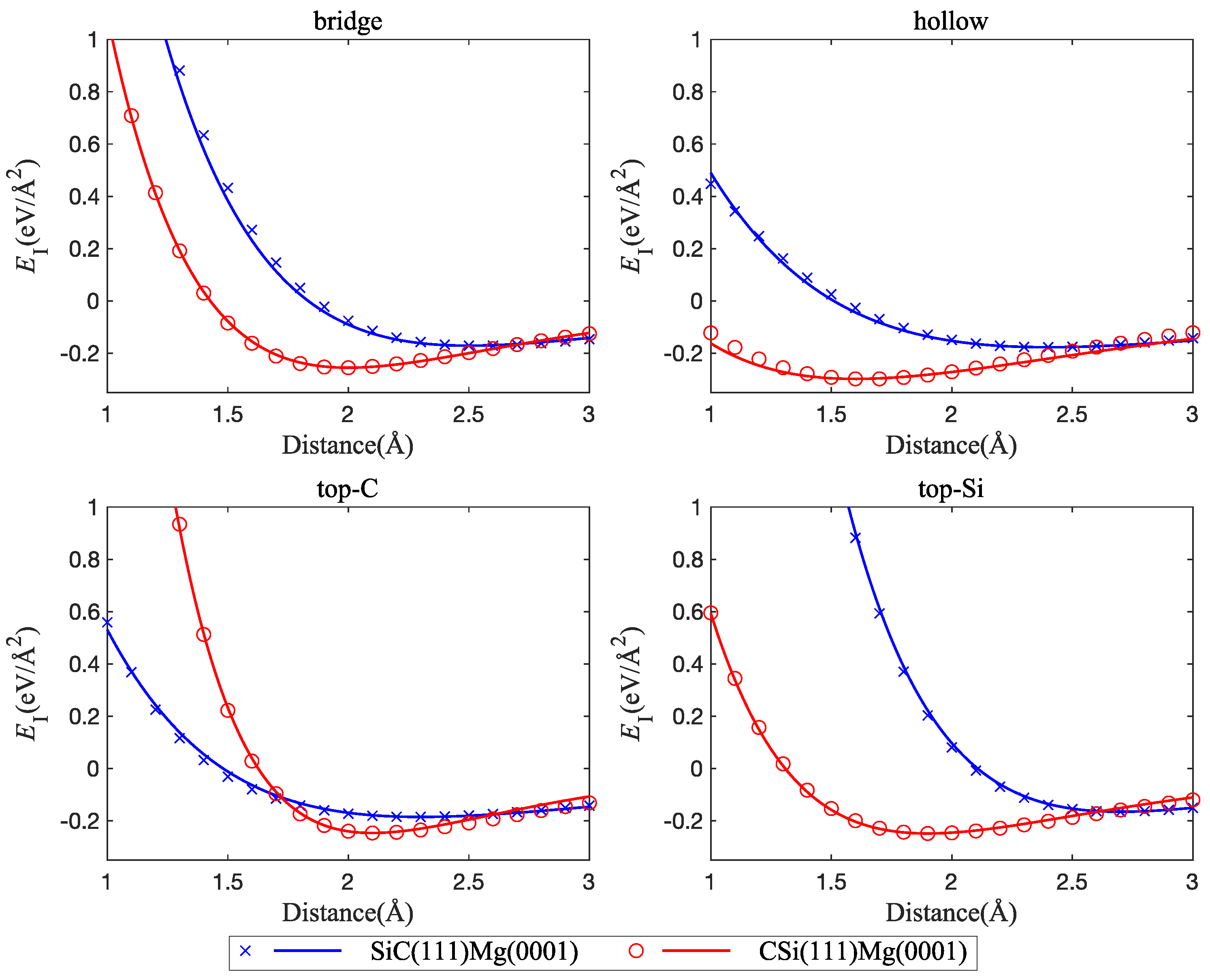
Figure 5.
Interface tensile stress curves, comparison of interfaces between Mg(0001) and C-terminated CSi(111) vs. Si-terminated SiC(111); four interface configurations are considered: bridge, hollow, top-C, and top-Si.
Figure 5.
Interface tensile stress curves, comparison of interfaces between Mg(0001) and C-terminated CSi(111) vs. Si-terminated SiC(111); four interface configurations are considered: bridge, hollow, top-C, and top-Si.

Figure 6.
Comparison between interface energy curves for interfaces between CSi(111) and two different orientations of the Mg slab: Mg(0001) and Mg(100); four interface configurations are considered: bridge, hollow, top-C, and top-Si.
Figure 6.
Comparison between interface energy curves for interfaces between CSi(111) and two different orientations of the Mg slab: Mg(0001) and Mg(100); four interface configurations are considered: bridge, hollow, top-C, and top-Si.

Figure 7.
Interface tensile stress curves, comparison of interfaces between CSi(111) and two different orientations of the Mg layer: Mg(0001) and Mg(100); four interface configurations are considered: bridge, hollow, top-C, and top-Si.
Figure 7.
Interface tensile stress curves, comparison of interfaces between CSi(111) and two different orientations of the Mg layer: Mg(0001) and Mg(100); four interface configurations are considered: bridge, hollow, top-C, and top-Si.

Figure 8.
Interface energy surfaces: (top left), CSi(111)Mg(0001); (top right) SiC(111)Mg(0001); (bottom left), CSi(111)Mg(100); (bottom right), Si(111)Mg(100); the lines marked P1 and P2 indicate the directions along which energy and IFSS profiles were taken.
Figure 8.
Interface energy surfaces: (top left), CSi(111)Mg(0001); (top right) SiC(111)Mg(0001); (bottom left), CSi(111)Mg(100); (bottom right), Si(111)Mg(100); the lines marked P1 and P2 indicate the directions along which energy and IFSS profiles were taken.
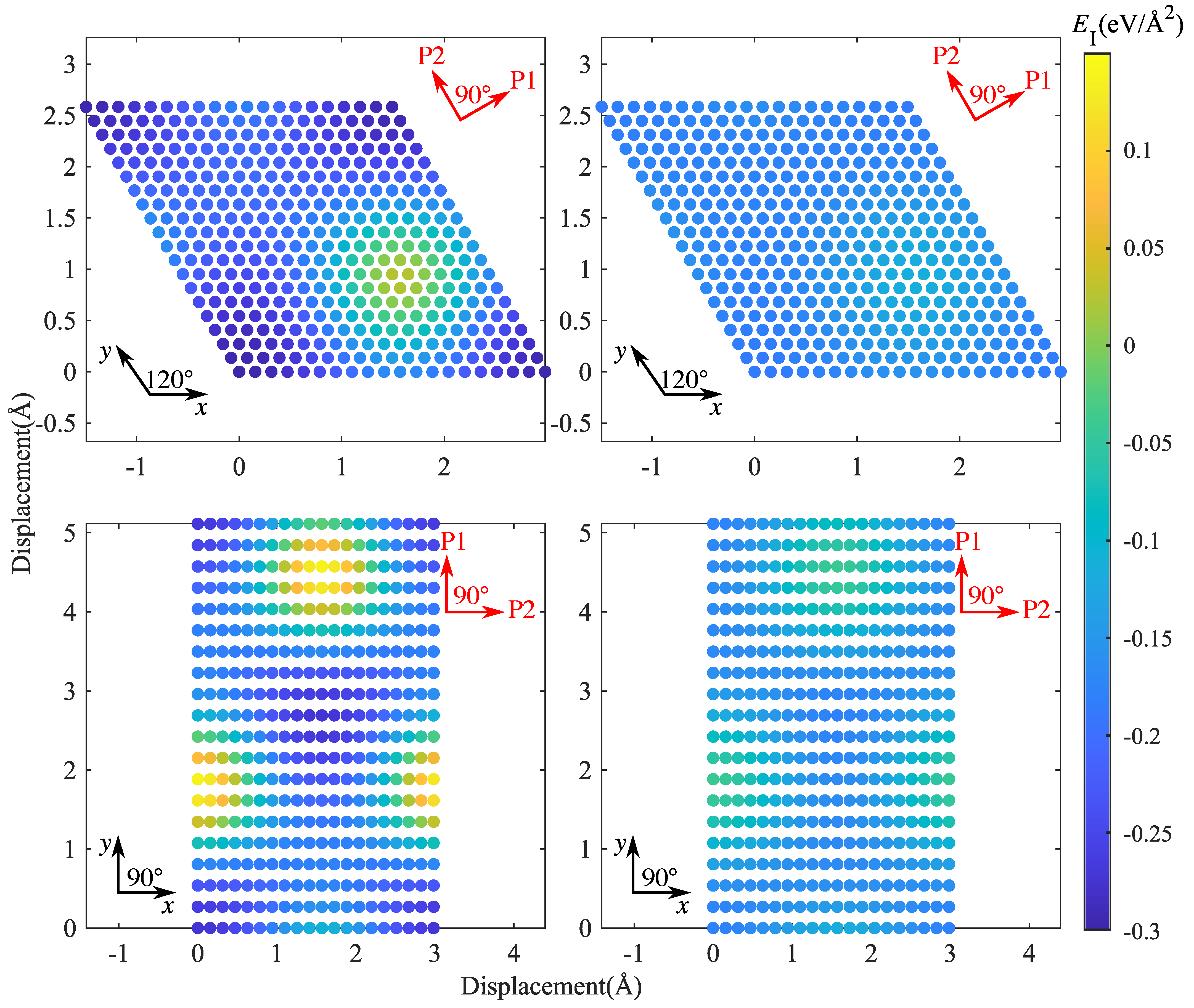
Figure 9.
Interface energy and IFSS profiles taken along the lines indicated by P1 and P2 in Figure 8: top, CSi(111)Mg(0001); bottom, SiC(111)Mg(0001); P1 = [] (Mg)/[] (SiC), P2 = [] (Mg)/[] (SiC).
Figure 9.
Interface energy and IFSS profiles taken along the lines indicated by P1 and P2 in Figure 8: top, CSi(111)Mg(0001); bottom, SiC(111)Mg(0001); P1 = [] (Mg)/[] (SiC), P2 = [] (Mg)/[] (SiC).
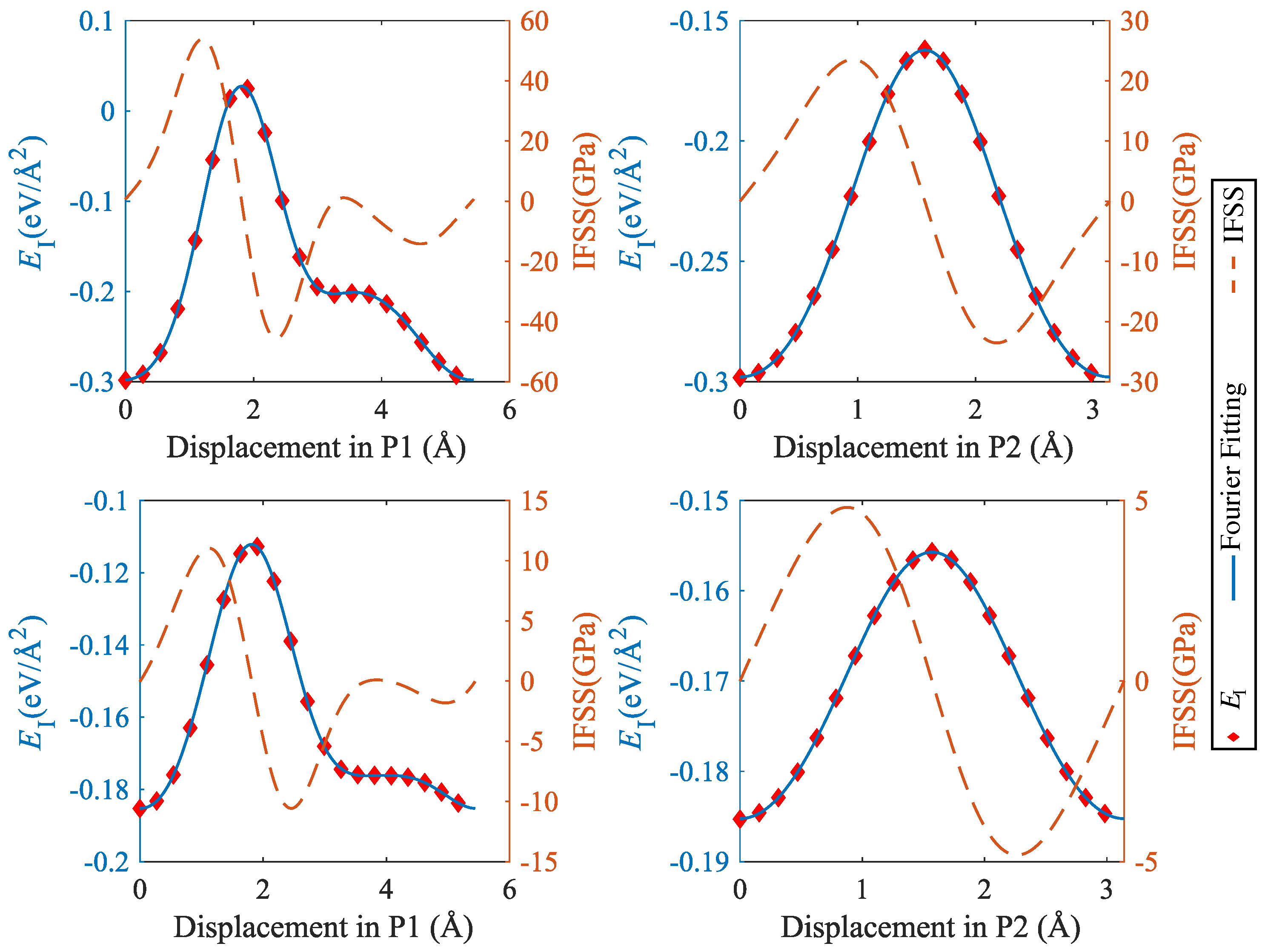
Figure 10.
Interface energy and IFSS profiles taken along the lines indicated by P1 and P2 in Figure 8; top: CSi(111)Mg(100), bottom: SiC(111)Mg(100); P1 = [0001] (Mg)/[] (SiC), P2 = [] (Mg)/[10] (SiC).
Figure 10.
Interface energy and IFSS profiles taken along the lines indicated by P1 and P2 in Figure 8; top: CSi(111)Mg(100), bottom: SiC(111)Mg(100); P1 = [0001] (Mg)/[] (SiC), P2 = [] (Mg)/[10] (SiC).

Table 1.
Minimum interface energies, corresponding interface distances, and maximum separation stresses for the investigated configurations.
Table 1.
Minimum interface energies, corresponding interface distances, and maximum separation stresses for the investigated configurations.
| Structure | Distance | Interface | Interface Separation | |
|---|---|---|---|---|
| (Å) | Energy (eV/Å2) | Stress (GPa) | ||
| Pure Mg | Mg(0001) | 2.7 | −0.060500 | 4.460038 |
| Mg(100) | 0.9 | −0.108209 | 6.484934 | |
| SiC(0001)Mg(0001) | Bridge | 2.6 | −0.169673 | 14.049061 |
| Hollow | 2.4 | −0.174717 | 11.654373 | |
| Top-C | 2.3 | −0.187171 | 13.768239 | |
| Top-Si | 2.7 | −0.161086 | 16.110159 | |
| SiC(111)Mg(0001) | Bridge | 2.5 | −0.171062 | 15.122863 |
| Hollow | 2.4 | −0.177111 | 11.729763 | |
| Top-C | 2.3 | −0.185225 | 13.320760 | |
| Top-Si | 2.7 | −0.165431 | 16.431664 | |
| SiC(111)Mg(100) | Bridge | 2.4 | −0.154134 | 12.344458 |
| Hollow | 2.1 | −0.168706 | 11.051431 | |
| Top-C | 2.0 | −0.177307 | 13.329418 | |
| Top-Si | 2.6 | −0.141755 | 13.083605 | |
| CSi(0001)Mg(0001) | Bridge | 2.0 | −0.237623 | 25.532947 |
| Hollow | 1.7 | −0.269242 | 19.127228 | |
| Top-C | 2.1 | −0.239356 | 30.143036 | |
| Top-Si | 2.0 | −0.222081 | 21.714480 | |
| CSi(111)Mg(0001) | Bridge | 2.0 | −0.255329 | 26.274945 |
| Hollow | 1.6 | −0.298127 | 21.691221 | |
| Top-C | 2.1 | −0.246606 | 30.672501 | |
| Top-Si | 1.9 | −0.248441 | 24.758893 | |
| CSi(111)Mg(100) | Bridge | 1.9 | −0.208181 | 19.599136 |
| Hollow | 1.4 | −0.273121 | 17.279160 | |
| Top-C | 2.0 | −0.195017 | 23.277400 | |
| Top-Si | 1.7 | −0.219156 | 21.113666 | |
Disclaimer/Publisher’s Note: The statements, opinions and data contained in all publications are solely those of the individual author(s) and contributor(s) and not of MDPI and/or the editor(s). MDPI and/or the editor(s) disclaim responsibility for any injury to people or property resulting from any ideas, methods, instructions or products referred to in the content. |
© 2024 by the authors. Licensee MDPI, Basel, Switzerland. This article is an open access article distributed under the terms and conditions of the Creative Commons Attribution (CC BY) license (https://creativecommons.org/licenses/by/4.0/).
Share and Cite
MDPI and ACS Style
Yao, Z.; Nasiri, S.; Yang, M.; Zaiser, M. Mechanical Properties of Interfaces between Mg and SiC: An Ab Initio Study. Metals 2024, 14, 467. https://doi.org/10.3390/met14040467
AMA Style
Yao Z, Nasiri S, Yang M, Zaiser M. Mechanical Properties of Interfaces between Mg and SiC: An Ab Initio Study. Metals. 2024; 14(4):467. https://doi.org/10.3390/met14040467
Chicago/Turabian StyleYao, Zhipeng, Samaneh Nasiri, Mingjun Yang, and Michael Zaiser. 2024. "Mechanical Properties of Interfaces between Mg and SiC: An Ab Initio Study" Metals 14, no. 4: 467. https://doi.org/10.3390/met14040467
Note that from the first issue of 2016, this journal uses article numbers instead of page numbers. See further details here.