Article

Improving the Interfacial Bonding Strength of Laser Direct Joining between Dissimilar 304 Stainless Steel and PCCF30 Plastic

School of Mechanical Engineering, Jiangsu University, Zhenjiang 212013, China
*
Author to whom correspondence should be addressed.
Metals 2024, 14(8), 924; https://doi.org/10.3390/met14080924
Submission received: 3 July 2024 / Revised: 8 August 2024 / Accepted: 13 August 2024 / Published: 15 August 2024
(This article belongs to the Section Welding and Joining)

Abstract

:
In response to the issue of weak laser connection strength between 304 stainless steel and the carbon fiber-reinforced polymer PCCF30, this study proposes the addition of a polyethylene terephthalate (PET) intermediate layer between 304 stainless steel and PCCF30, along with surface texture pretreatment of the stainless steel surface, to enhance the joint connection strength. First, three types of surface textures (vertical, wavy, and vertical plus wave) were investigated for their effect on joint quality. Once the optimal texture type was determined, the effect of texture scanning repetition on the surface morphology and groove cross-sectional geometry of 304 stainless steel was examined. The joint strengths achieved by adding intermediate layers and employing different surface texture treatment methods were compared, followed by a comparison of the joint strengths obtained from different pretreatment methods. Finally, the connection mechanism of the joint was analyzed. The results indicated that the maximum joint strength achieved through the vertical and wavy texture design was 4.39 MPa, which is 3.3 times greater than that achieved without reinforcement. Moreover, the maximum joint strength achieved with the addition of a PET intermediate layer and surface texture composite treatment was 11.85 MPa, which is approximately nine times greater than that achieved via direct connection. The inclusion of a PET intermediate layer enhances the fluidity of the molten polymer at the joint, facilitating better filling of the grooves with surface texture. This strengthens the mechanical anchoring effect of the joint and contributes to the improvement in the joint’s connection strength. An XPS analysis revealed that after multiple etchings of the joint interface with an added intermediate layer, the Cr in the stainless steel chemically bonded with the PET, resulting in the formation of Cr–O–C chemical bonds, which is advantageous for enhancing joint quality.

Graphical Abstract

1. Introduction

In the past century, carbon fiber-reinforced thermoplastic composites (CFRTPs) have been widely applied in various fields, such as automobile, medical device, and ship production, due to their highly specific modulus and strength, ease of processing and forming, and excellent fatigue resistance [1,2,3]. Meanwhile, 304 stainless steel, as the most commonly used type of chromium nickel stainless steel, is extensively used in household goods, automotive components, medical devices, ships, and other sectors due to its exceptional corrosion resistance, heat resistance, low-temperature strength, and mechanical properties [4,5]. In practical industrial manufacturing, there is a need to effectively combine different materials to harness their respective advantages. The connection between metals and thermoplastic polymers has become an urgent problem that needs to be addressed in industrial production. Consequently, the development of efficient, reliable, and cost-effective connection processes has emerged as a crucial research and development priority [6,7,8].
The conventional association between metals and polymers primarily entails adhesive and mechanical connections, which are typically utilized for basic structural components. For adhesive connections, curing takes some time [9,10]. For example, Matteo et al. [10] used the Norland Optical Adhesive 74 (NOA74) to achieve PDMS–metal bonding. First, the PDMS surface was functionalized with (3-aminopropyl) triethoxysilane (APTES) for further cross-linking with epoxy groups. Then NOA74 is directly spun on top of the PDMS at 6000 rpm. After the NOA74 layer is created on the PDMS surface, PDMS and the substrate are put in contact and the glue is cured under a UV lamp (20 mW/cm2, 1.5 h). The inclusion of fasteners in mechanical connections can compromise sealing performance and increase the weight of the connection. Moreover, the adoption of bolts, nuts, and similar elements can lead to stress concentrations [11,12]. Presently, novel methods of connecting metals and polymers have emerged, exemplified by induction bonding [13], friction spot welding [14], ultrasonic bonding [15], and laser bonding [16]. Nonetheless, the use of a magnetic filler prior to induction connection processing can cause stress concentration in the joint. While the friction spot welding process is straightforward, it is primarily suitable for structurally simple components and may result in defects such as holes after connection [17]. Ultrasonic bonding is limited to lap joints and is best suited for thin or soft processed components, such as foils and sheets. In comparison to the aforementioned connection methods, laser direct joining offers advantages such as high processing efficiency, fewer defects, good controllability, and seamless automation implementation [18,19]. Consequently, in the domain of metal-polymer connections, direct laser connections are particularly advantageous because they satisfy the substantial demand for lightweight production in industrial settings.
Given the considerable potential of laser connection technology in the industrial lightweight field, numerous scholars have conducted extensive research on laser connections between metals and thermoplastic polymers. In 2011, Roesner et al. from Germany investigated the effect of microgrooves on the strength of joints on stainless steel surfaces. Research has demonstrated that machining microgrooves on metal surfaces can significantly enhance the strength of joints between metals and polymers [20]. In 2014, Heckert et al. employed lasers to perform nanoscale, microscale, and macrogroove machining on metal surfaces and subsequently utilized laser direct joining technology to connect the pretreated metal to the polymer. The resulting joint shear strength reached 42 MPa. These results indicate that the groove pretreatment of metal surfaces can substantially enhance the connection strength between metals and polymers [21]. In 2016, Jung from the Republic of Korea conducted a study on the laser connection between galvanized steel and ABS. Prior to the laser connection, the galvanized steel plate underwent furnace oxidation as a pretreatment. The experimental results revealed that a zinc oxide layer formed on the surface of the treated galvanized steel, and Zn–O–C chemical bonds were established at the joint interface, significantly improving the strength of the connection between the galvanized steel and ABS [22]. In 2018, Shan et al. modified carbon fiber-reinforced polymer (CFRP) with acrylic acid during the laser connection of CFRPs with aluminum alloys. The results indicated a considerable increase in the strength of the modified joint. An X-ray photoelectron spectroscopy (XPS) analysis revealed that new chemical bonds between Al–C and Al–O–C were generated at the connection interface [23]. In 2020, Cárcel investigated the effects of laser surface shape, joint temperature, and laser connection time on the strength of joints between 304 stainless steel and glass fiber-reinforced acrylic resin. The research demonstrated that the optimal joint strength was achieved when the temperature at the joint interface was 220 °C. Excessive temperatures led to thermal decomposition of the polymer, while insufficient temperatures resulted in inadequate melting of the polymer, both of which diminished the joint strength [24].
Research has demonstrated the significant enhancement in joint strength between metals and polymers through laser surface texture treatment. However, the majority of existing studies have focused only on the examination of the texture treatment’s process parameters and mechanisms. Furthermore, limited research has explored the overlap between texture pretreatment methods and other enhancement techniques. Therefore, this article aims to address these gaps by employing a nanosecond pulsed laser to treat the surface of 304 stainless steel and carbon fiber-reinforced polycarbonate (PCCF30) during laser-enhanced connection. To facilitate this connection, thin films with excellent compatibility with carbon fiber-reinforced polymer substrates were introduced between the two materials. The nanosecond pulse laser allows for the precise and efficient adjustment of the parameters (such as width and depth) of the grooves on the stainless steel surface, which is advantageous for optimizing the texture process parameters and laser direct joining process parameters in subsequent stages. Considering the poor flowability of the PCCF30 substrate polycarbonate (PC) [25], an intermediate layer was selected to improve the flowability of the molten material in the joint while ensuring compatibility between the intermediate layer, polymer, and metal. Wangfei Su of Donghua University investigated the effect of the polyethylene terephthalate (PET) content in blends of PET and PC on the viscosity of the blends and concluded that the addition of PET effectively enhances flowability. Research utilizing FTIR, SEM, and DSC analyses demonstrated that the ester exchange reaction in PET and PC blends improved the compatibility of the two materials [26]. The improvement in compatibility helps to reduce phase separation, making the blend more uniform during processing, which in turn enhances its flowability. Similarly, Miyashita et al. from Japan conducted laser direct joining between 304 stainless steel and PC and PET and compared the quality of the resulting joints [27]. Their findings revealed that the weldability and shear strength of the joints between PET and 304 stainless steel are significantly greater than those between PC and 304 stainless steel. Drawing upon these prior investigations, PET has been identified as a material that not only demonstrates remarkable bonding capabilities with 304 stainless steel [27] but also effectively enhances the flowability of PC [26]. Consequently, PET was chosen as the optimal intermediate layer for this application. PET exhibits excellent thermal stability, enabling it to maintain relative stability during the laser joining process without easily decomposing. This study performed texture pretreatments [28] on the surface of 304 stainless steel and incorporated a PET intermediate layer between 304 stainless steel and PCCF30 to enhance the strength of the joint. This study investigated the influence of different texture types on joint strength and explored the optimal texture type and geometric morphology. Furthermore, the effect of various pretreatment methods on joint strength was examined while exploring the underlying connection mechanisms.

2. Experimental Design

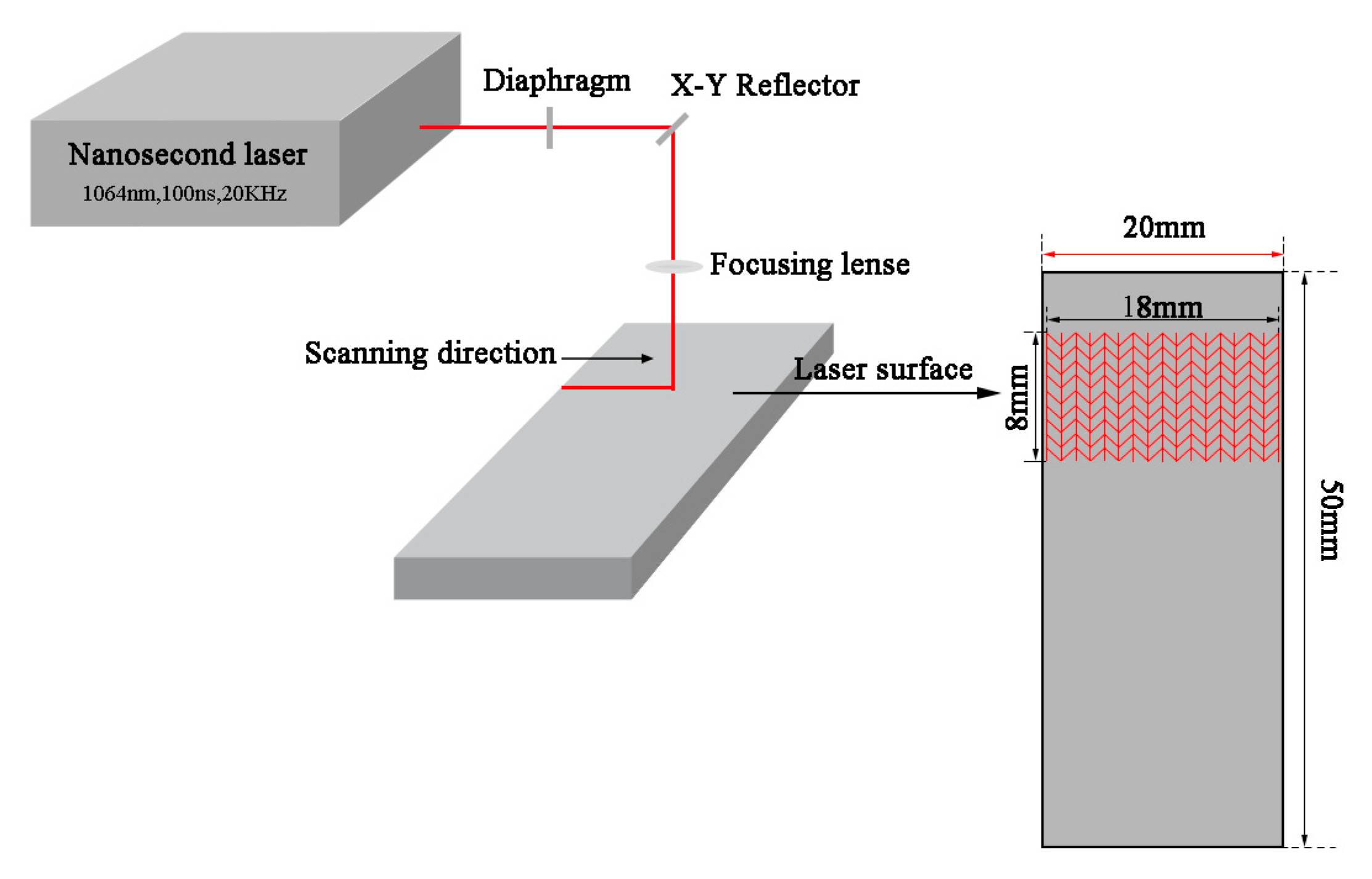
2.1. Sample Preparation and Experimental Procedure

The metallic material utilized in this study was 304 stainless steel, while the CFRP consisted of a PC matrix and 30% short carbon fibers (by volume). Both specimens had dimensions of 50 mm × 20 mm × 20 mm. The intermediate layer material employed was PET, which was utilized as thin sheets measuring 20 mm × 20 mm in size and ranging in thickness from 0.05 mm to 0.30 mm. Prior to the laser joining experiment, the experimental materials were subjected to a 10-min ultrasonic cleaning process and subsequently placed in an electronic drying oven for 12 h. The surface texture treatment of the stainless steel was carried out using a K20-CS fiber laser surface treatment system manufactured by Shenzhen Han’s Laser (Shenzhen, China). This system employs a German YLP-1-100-20-20 nanosecond pulsed fiber laser generator with a maximum output power of 20 W, a scanning speed range of 0 mm/s to 7000 mm/s, a wavelength of 1064 nm, a spot diameter of approximately 30 μm, and a pulse width of 100 ns. The laser joining of 304 stainless steel and PCCF30 was performed using the WF1500 continuous-fiber laser joining system produced by Mingyang Laser Technology Co., Ltd. (Changzhou, China)., with a maximum output power of 1500 W, and the spot size of the laser for joining was 0.5 mm.
The joint connection mechanism and the joints (after tensile testing) were examined using a VHX-600E superdepth three-dimensional microscope manufactured by the Keyence Corporation (Osaka, Japan). The tensile testing of the joints was conducted using a UTM4104 electronic universal testing machine manufactured by Shenzhen Sansi Zongheng (Shenzhen, China), with a maximum tensile limit of 10 kN.

2.2. Surface Texture Pretreatment of 304 Stainless Steel

Surface textures were created on 304 stainless steel utilizing a nanosecond pulsed laser. The size of the textured area on the stainless steel surface was 18 mm × 8 mm, as depicted in Figure 1. The effects of the laser joining power, laser joining speed, texture spacing, and texture scanning times on the experiment were investigated. During the pretreatment of the surface texture of the stainless steel, the spacing between the front and back textures in the 8 mm width direction was adjusted to vary the texture spacing, while the distance in the 18 mm length direction remained constant. The depth of the metal surface texture was modified by manipulating the number of texture scans. The other laser surface texture processing parameters were held constant, at a scanning speed of 500 mm/s, a pulse frequency of 20 kHz, and a power of 16 W (80%). The laser was focused at the intended plane with no defocusing. The time required for the surface texture pretreatment was approximately 2 min.

2.3. Experimental Scheme Based on Adding an Intermediate Layer and Surface Texture for Laser Direct Joining

Figure 2a shows a schematic diagram illustrating the laser direct joining of 304 stainless steel and PCCF30 after the surface texture pretreatment. Figure 2b shows a schematic diagram of the laser direct joining of 304 stainless steel and PCCF30 after surface texture and intermediate layer addition. First, the surface of the 304 stainless steel was pretreated using a nanosecond pulsed laser. The connection between the stainless steel and PCCF30 was achieved by overlapping the materials. The stainless steel was placed on top of the PCCF30, with the metal texture facing downwards. A PET intermediate layer was incorporated between the stainless steel and the polymer. A semiconductor continuous laser irradiated the surface of the stainless steel, converting the absorbed light energy into heat and transferring it to the lower layers of the PET and PCCF30. Once enough heat was absorbed, the polymer reached a molten state and flowed into the grooves on the stainless steel surface due to a clamping force of 10 N. This process facilitated the connection between the two materials. The time required for laser direct joining was approximately 2 min, followed by a dwell pressure period of another 3 min after the joining.

3. Results and Discussion

3.1. Selection of Different Texture Types

In this experiment, we created three types of textures (vertical lines, wavy lines, and vertical lines combined with wavy lines) on the surface of stainless steel using a nanosecond pulsed laser. For each texture type, 15 scans were obtained, with the textured area measuring 18 mm × 8 mm. The laser joining speed was set at 10 mm/s, and the laser joining power was varied between 500 W, 600 W, and 700 W. Figure 3 illustrates the shear strength of the joints obtained from the four groups of experiments.
From the figure, it is evident that the joints formed with a texture pretreatment exhibited significantly greater shear strength than did those of the control group without texture treatment. When the laser power was set at 650 W and the joining speed was 10 mm/s, the joints formed by the three different types of texture treatment reached their maximum shear strength. Among them, the joint formed by the stainless steel and PCCF30 with vertical lines combined with wavy lines had the highest shear strength (4.39 MPa), followed by the joint formed by the stainless steel and PCCF30 with vertical lines with a shear strength of 2.15 MPa. The joint formed by the stainless steel and PCCF30 with a wavy line texture exhibited a shear strength of 3.24 MPa, while the joint without texture treatment had a shear strength of 1.33 MPa.

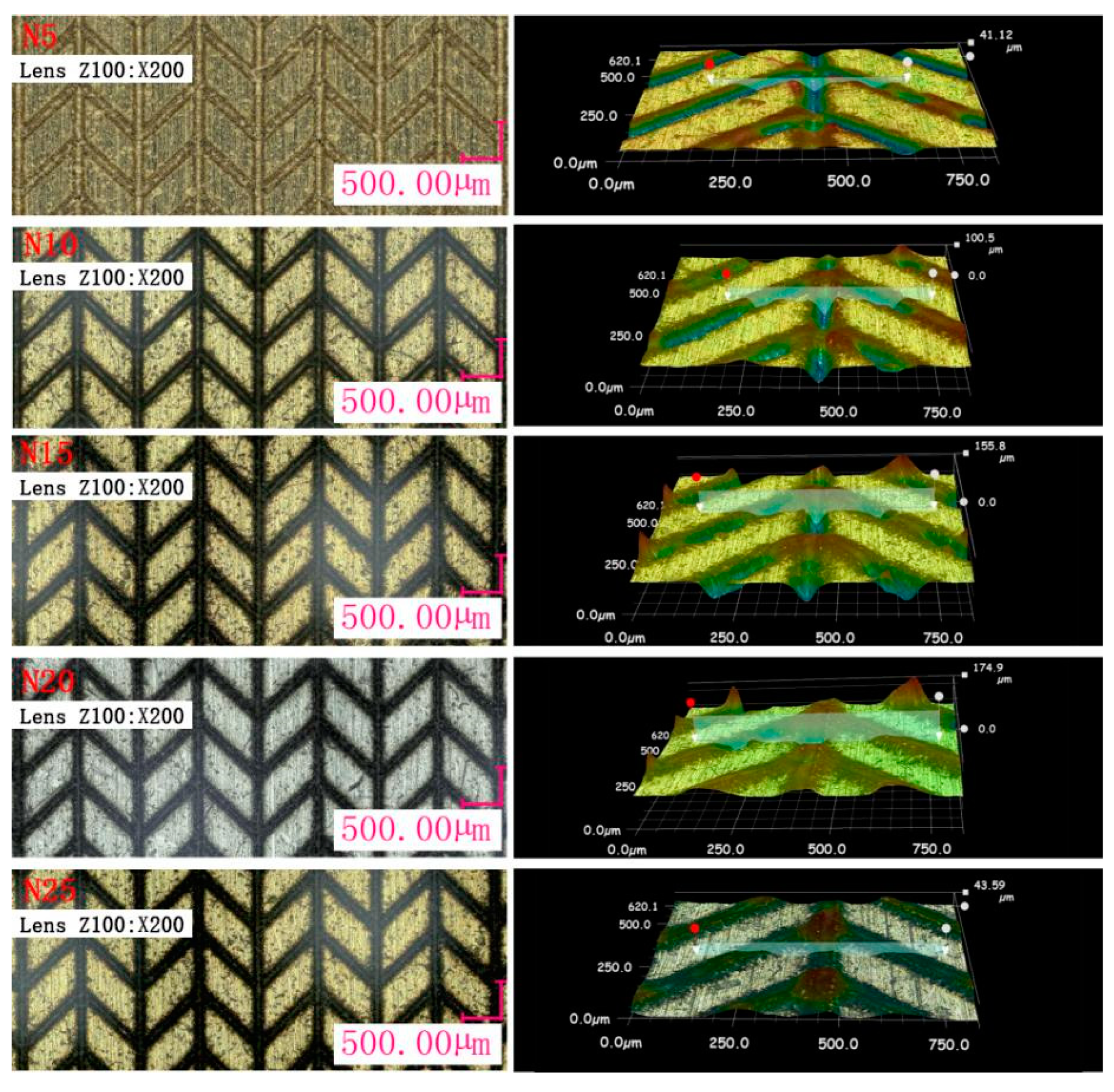
3.2. Analysis of the Stainless Steel Surface Texture Geometric Morphology

Figure 4 shows the stainless steel surface’s morphology for various numbers of texture scans (5, 10, 15, 20, and 25) with a fixed texture spacing of 0.5 mm. The corresponding cross-sectional morphology of the grooves is depicted in Figure 5. Combining Figure 4 and Figure 5, it is evident that the cross-sectional shape of the grooves demonstrates distinct characteristics based on the number of texture scans conducted. When the number of texture scans was set at five, the grooves exhibited a semicircular and regular shape. Conversely, with 10 texture scans, the grooves took on a rectangular and regular shape. As the number of texture scans increased even further, a noticeable transformation occurred, resulting in slender and inverted cone-shaped grooves. This transformation can be attributed to the greater build-up of heat on the metal surface caused by the increased number of scans. Consequently, molten stainless steel was consistently discharged from the inside to the outside and accumulated on the sides of the grooves, giving rise to protrusions near the metal surface.
Figure 5 shows that bulges formed on both sides of the grooves after the laser scanning of the stainless steel surface. In the process of laser joining, these bulges embed into the molten polymer, enhancing the anchoring effect and ultimately improving joint quality. As the number of texture scans continued to increase, the width of the grooves initially increased slightly before gradually decreasing. Simultaneously, the depth of the grooves increased. At the 10th texture scan, the width of the grooves reached a maximum value of 118.83 μm. Conversely, at 25 texture scans, the width of the grooves decreased to a mere 31.83 μm, while the cross-sectional shape transformed into a slender and inverted cone shape. This transformation occurred due to the accumulation of molten stainless steel on the sides of the grooves as the number of texture scans increased, leading to a decrease in groove width. These changes in groove width based on the number of texture scans are visually demonstrated in Figure 6a.
Furthermore, Figure 5 also indicates that the maximum depth of the groove gradually increased as the number of texture scans increased from 10 to 25, as depicted in Figure 6b. However, once the number of texture scans reached 20 or more, the groove interior became significantly filled and obstructed. Even at 25 texture scans, despite the maximum groove depth reaching 464.75 μm, the width was only 31.83 μm. This occurrence was attributed to the continuous outflow of molten stainless steel from the bottom of the groove to the sides, intensifying the issue of filling and blockage within the groove.
The micromorphology of the joint cross-sections at different numbers of texture scans is illustrated in Figure 7. The number of texture scans varied from 5 to 25, while the laser direct joining power was fixed at 650 W, the laser joining speed was kept constant at 10 mm/s, and the texture spacing was maintained at 0.5 mm. The other process parameters were also kept consistent. The joint morphology was observed using a superdepth three-dimensional microscope.
Figure 7 shows that when the number of texture scans was set to 5, the grooves on the stainless steel surface were completely filled with molten PCCF30. However, when the number of texture scans was increased to 10, small voids were found in the grooves, implying incomplete filling of the molten PCCF30. Moreover, with 15 texture scans, the area of voids in the grooves increased. This was attributed to the fact that as the number of texture scans increased, the width of the grooves decreased while the depth of the grooves increased. Consequently, this change was not conducive to the proper flow of molten PCCF30 into the grooves.
Furthermore, when the number of texture scans was greater than 20, the volume of molten PCCF30 embedded in the surface texture of the stainless steel gradually decreased. This was because as the number of texture scans further increased, although the maximum depth of the grooves gradually increased, the effective depth and width of the grooves gradually decreased. Consequently, this resulted in the slender, inverted, cone-shaped cross-sectional shape of the grooves, which increased the resistance to the flow of molten PCCF30 into the grooves. Ultimately, this led to a reduction in the volume of molten PCCF30 embedded in the grooves and a weakening of the anchoring effect, thereby reducing the strength of the joints. Based on the aforementioned analysis, the optimal joint connection effect is achieved when the number of texture scans is set to 10.

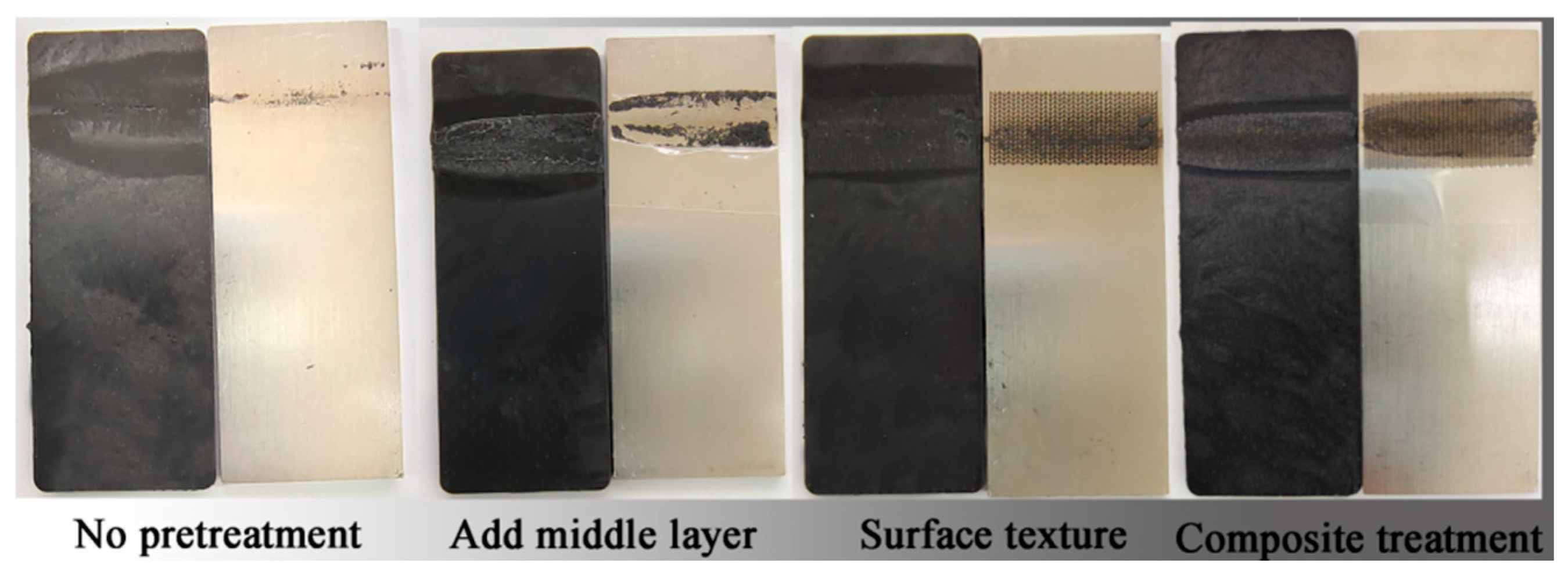
3.3. Comparison of Joint Strength for Different Pretreatment Methods

To determine the best reinforcement treatment method, laser direct joining experiments were conducted on the surface-treated stainless steel and PCCF30, stainless steel and PCCF30 with an intermediate layer added, and stainless steel and PCCF30 with composite treatment. The laser joining speed was fixed at 10 mm/s, while the laser joining power ranged from 500 W to 700 W. The texture spacing was set to 0.3 mm, and the texture scan number was 10. Additionally, the thickness of the intermediate layer was set to 0.05 mm. The shear strength of the joints is illustrated in Figure 8.
The figure clearly shows that at a laser joining speed of 10 mm/s, all three pretreatment methods significantly contributed to enhancing the quality of the joints. The inclusion of an intermediate layer resulted in a maximum joint strength of 2.81 MPa, which was approximately double that of direct joining without the reinforcement treatment. After the texture treatment, the maximum joint strength increased to 7.81 MPa, which was approximately six times greater than that of the direct joining without pretreatment. The composite treatment yielded the highest maximum joint strength of 11.85 MPa, which was approximately nine times greater than that of the direct joining without pretreatment. Notably, the joint shear strength obtained from the composite treatment was significantly superior to that obtained from the other two individual treatments due to various factors. The addition of a PET intermediate layer improved the flowability of the molten polymer at the joint interface, leading to greater embedding of the molten polymer in the grooves on the stainless steel surface and enhancing the mechanical riveting effect. Moreover, the chemical bonds that formed at the joint interface after adding the PET intermediate layer further enhanced the shear strength of the joints. Consequently, the joint strength obtained from the composite treatment was notably superior to that obtained from the other two individual treatments.
Figure 9 shows micrographs of the joints following failure under the different pretreatment methods. It is evident that the joint without reinforcement treatment exhibited minimal residual polymer on the stainless steel side. However, for the joints with an intermediate layer added, texture treatment, and composite treatment, more polymer residues were observed on the stainless steel side. Notably, compared with the individual texture treatments, the composite treatment led to a significant decrease in the size of the weld bead. This can be attributed to the improved flow of the molten polymer into the grooves on the stainless steel surface, facilitated by the addition of the PET intermediate layer.

3.4. Analysis of the Connection Mechanism

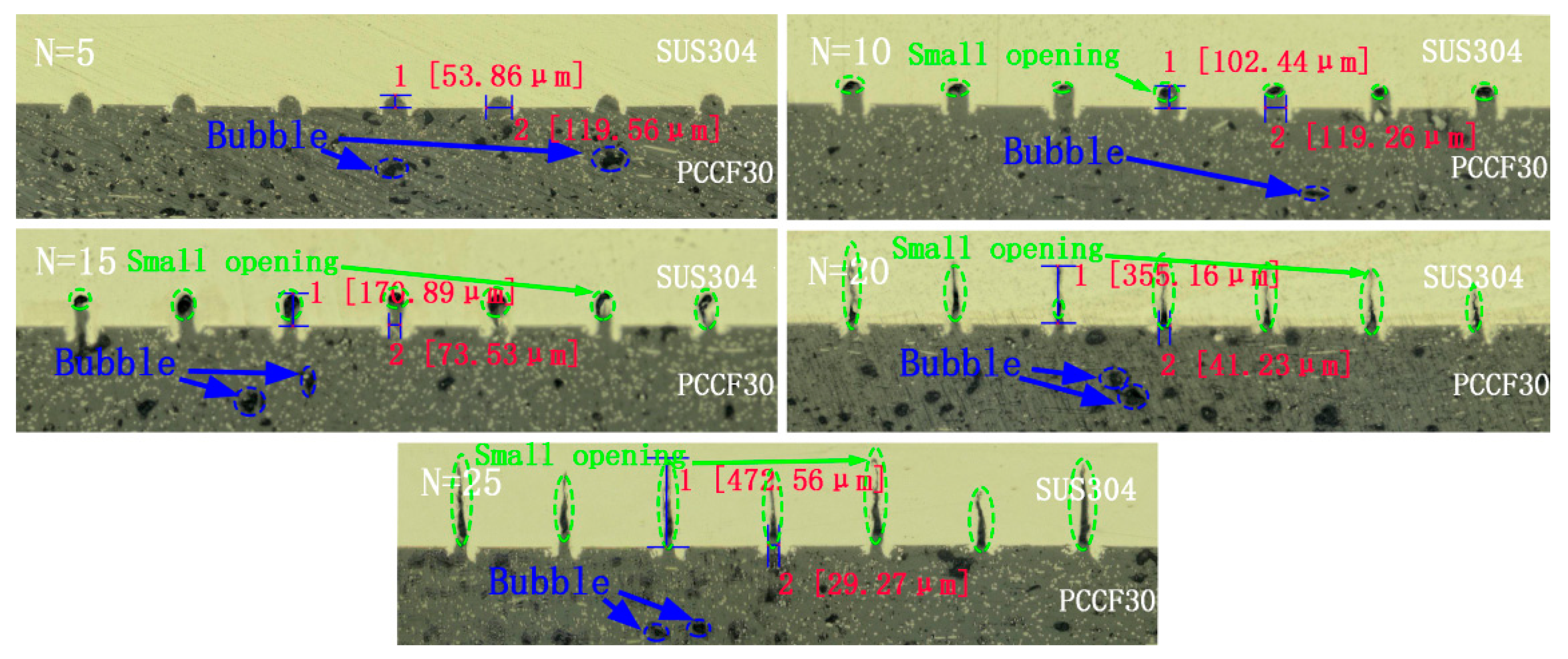
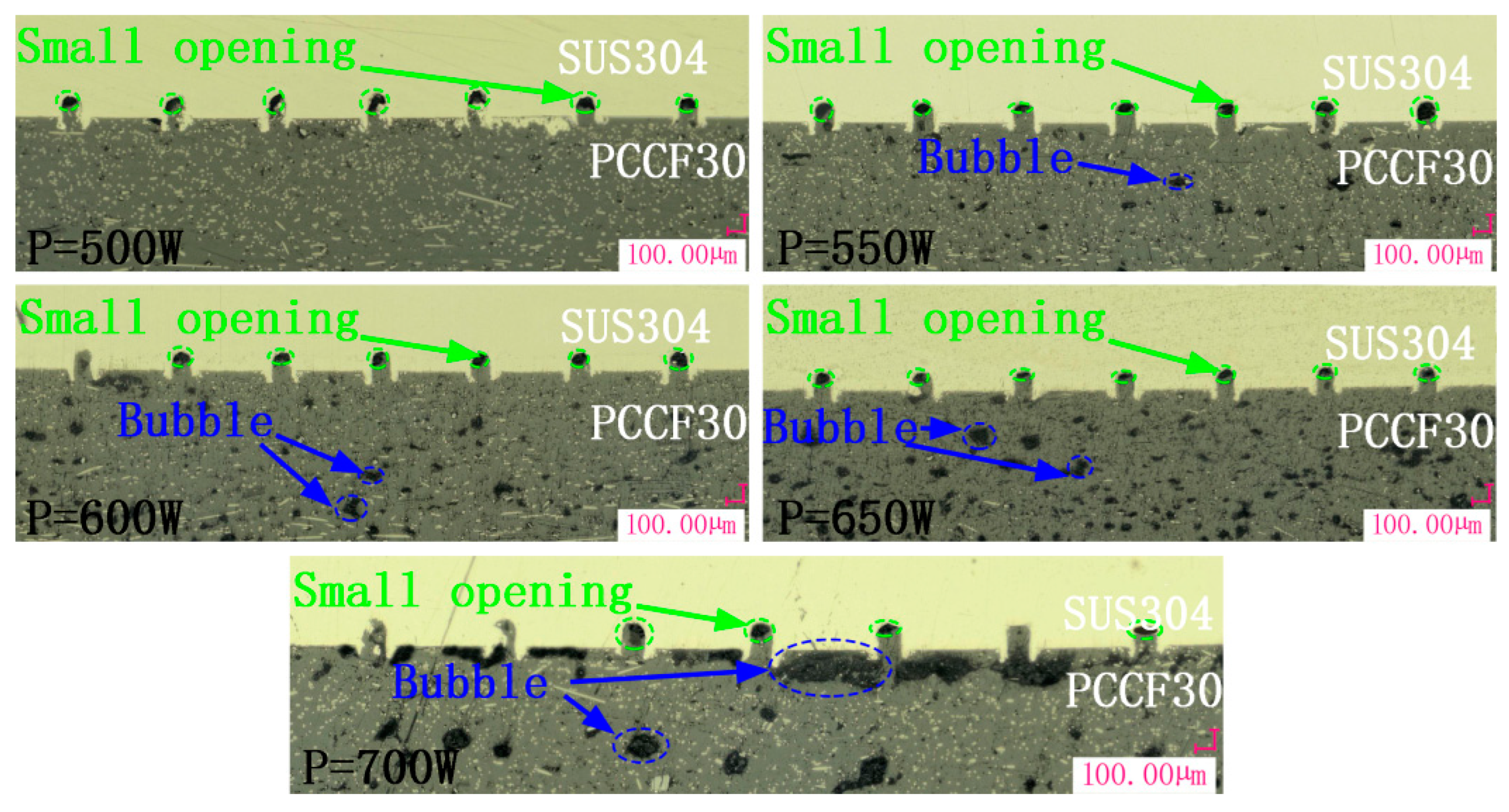
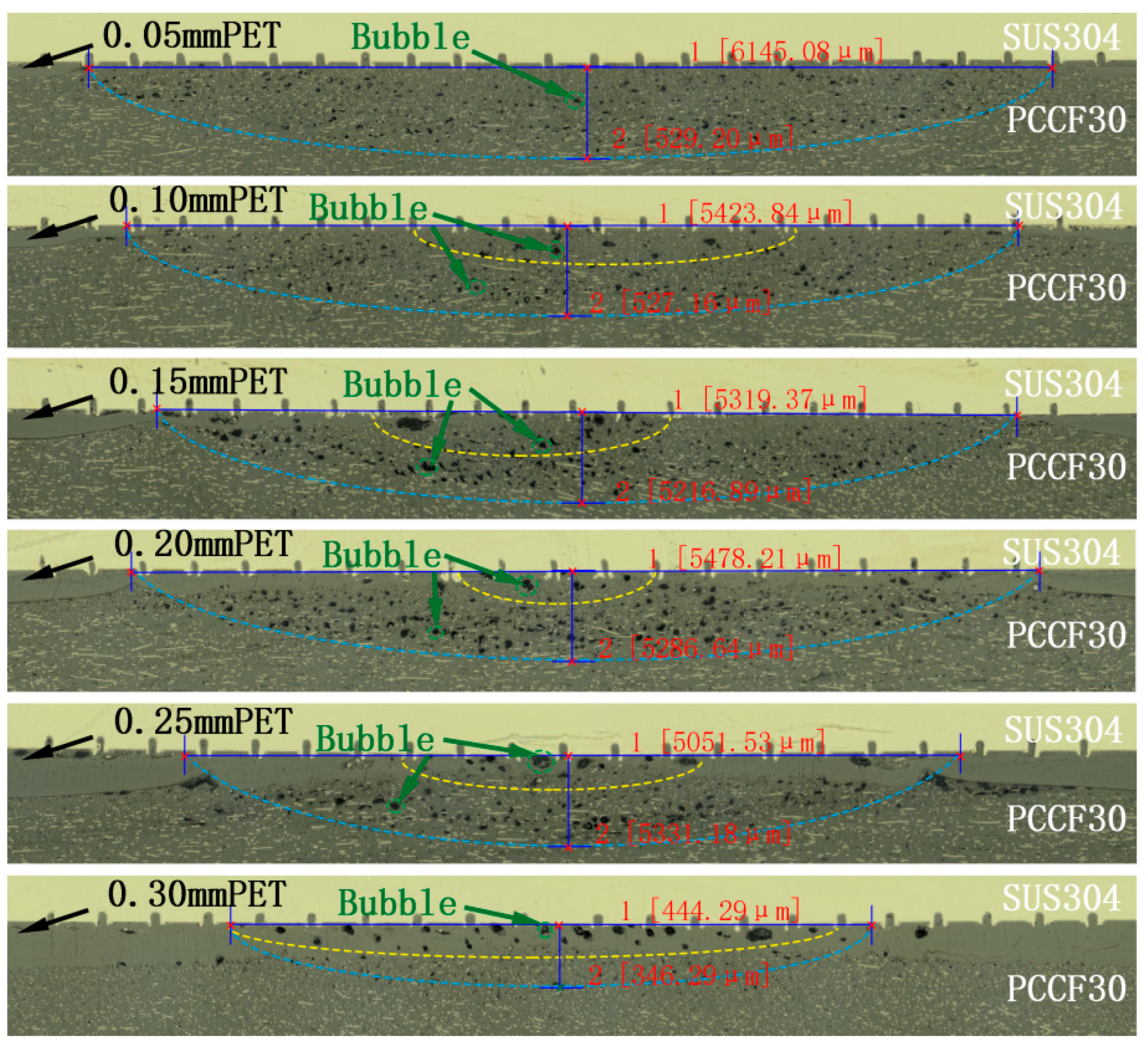
3.4.1. Analysis of the Cross-Sectional Morphology of Joints

To further investigate the connection mechanism following the addition of an interlayer and textured pretreatment, the cross-sectional morphology of the reinforced joints was observed.
(1)
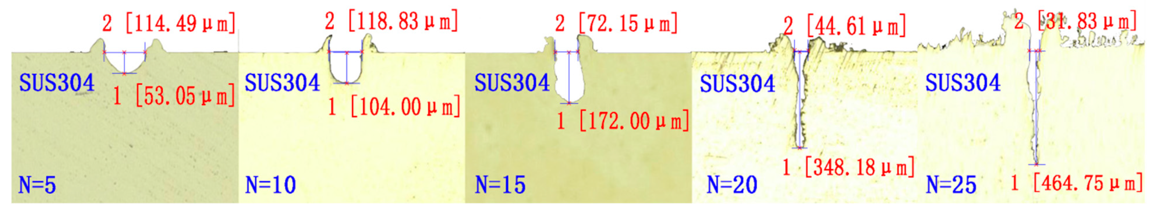
Influence mechanism of different laser joining powers, following surface texture treatment, on the connection performance
The micromorphology of the joint cross-sections under varying laser direct joining powers is depicted in Figure 10. The laser powers were set at 500 W, 550 W, 600 W, 650 W, or 700 W, while maintaining a fixed laser joining speed of 10 mm/s, a fixed texture spacing of 0.5 mm, and a fixed texture scanning count of 10 times. Other process parameters remained constant. The joint’s morphology was observed using a high-resolution, three-dimensional microscope to ensure an accurate examination.
Figure 10 clearly shows that at a laser power of 500 W, no discernible bubbles were detected within the PCCF30 material. Furthermore, the melted PCCF30 did not completely fill the grooves of the stainless steel surface texture, with only approximately half of the depth of the groove being occupied. As the laser power increased, additional PCCF30 material was successfully embedded in the grooves. A significant proportion of the groove area was occupied by the PCCF30 material when the laser joining power reached 700 W.
This trend can be attributed to the lower laser power resulting in insufficient melting of the PCCF30 material, preventing it from fully flowing into the grooves on the stainless steel surface. However, as the laser power progressively increased, the flowability of the melted PCCF30 improved, allowing more polymer to permeate into the grooves on the stainless steel surface. Despite this, due to the inherent limitations of the flowability of the PCCF30 material, even at a laser power of 700 W, the grooves on the stainless steel surface were not entirely filled.
From Figure 10, it is evident that there was an absence of noticeable bubbles at the joint weld when the laser joining power was 500 W, suggesting that the laser power was relatively low, leading to insufficient heat absorption by PCCF30 to cause thermal decomposition. As the laser power increased, the volume and number of bubbles observed at the joint weld also increased. At a laser joining power of 700 W, larger bubbles were found near the stainless steel side of the PCCF30. This can be attributed to the higher laser joining power, which caused increased heat absorption by PCCF30 and resulted in thermal decomposition within the polymer. The severity of thermal decomposition intensified with the further increase in laser power, leading to more bubbles. These bubbles gradually aggregated and migrated toward the bonding area between the stainless steel and PCCF30, resulting in the accumulation of larger bubbles at the bonding area. Consequently, this reduced the shear strength of the joint. Researchers have confirmed the effect of bubbles on the strength of the connection. Katayama et al. discovered that the presence of small and uniformly distributed bubbles, resulting from thermal decomposition, contributes to the enhancement of connection strength in a study of laser joining of polymers and metals [29]. Farazila et al. reported that the presence of large bubbles within a polymer during laser joining diminishes joint quality [30].
(2)
Influence mechanism of different interlayer thicknesses, following surface texture treatment, on the connection performance
The micromorphology of the joint cross-sections, corresponding to different interlayer thicknesses, is depicted in Figure 11. The interlayer thicknesses were set at 0.05 mm, 0.10 mm, 0.15 mm, 0.20 mm, or 0.25 mm, while the other process parameters remained constant. The direct joining power was 650 W, the laser joining speed was 10 mm/s, the texture spacing was 0.5 mm, and the texture scanning count was 10×.
It is evident from the figure that when the interlayer thickness was 0.05 mm, the interlayer and the lower layer of the PCCF30 exhibited good compatibility within the heat-affected zone of the joint. However, for an interlayer thickness of 0.10 mm, discernible stratification between the interlayer and the lower layer of the PCCF30 was observed near the edge of the heat-affected zone. As the interlayer thickness gradually increased, the area of stratification between the interlayer and the lower layer of the PCCF30 also expanded. Upon reaching an interlayer thickness of 0.25 mm, evident stratification between the interlayer and the lower layer of the PCCF30 appeared throughout the heat-affected zone.
This phenomenon can be attributed to the transmission of heat during welding, which is distributed from the center to the periphery of the heat-affected zone, with the highest temperature occurring at the center. Consequently, the PET interlayer near the center fused effectively with the lower layer of the PCCF30, while separation between the interlayer and the lower layer of the PCCF30 occurred away from the central position of the heat-affected zone. With a further increase in the interlayer thickness, the heat absorbed by the PET interlayer failed to transfer efficiently to the lower layer of the PCCF30, resulting in stratification between the PET interlayer and PCCF30 throughout the entire joint.
Figure 11 illustrates that when the interlayer thickness was 0.05 mm, the bubbles within the polymer were small and evenly distributed. However, as the interlayer thickness increased, the heat-affected zone (the area marked by the blue dashed line) did not change significantly, but the larger bubbles’ zone (the area marked by the yellow dashed line) appeared on the side of the polymer near the stainless steel. Once the interlayer thickness reached 0.30 mm, the heat-affected zone significantly decreased in size, and bubbles were primarily concentrated on the side of the interlayer near the metal. These observations can be attributed to the low thermal conductivity of the PET interlayer. As the interlayer thickness increased, thermal accumulation became more likely in the PET interlayer, leading to thermal decomposition near the metal in the heat-affected zone and the aggregation of bubbles in that area. Additionally, Figure 11 also demonstrates that the addition of the PET interlayer resulted in filled grooves on the stainless steel surface with melted PET and PCCF30. This anchoring effect of the joint was significantly improved compared to that shown in Figure 9 without the interlayer. The superior flowability of PET compared to that of PCCF30 contributed to this enhancement. The inclusion of the PET interlayer improved the flowability of the molten material at the joint, facilitating its flow into the grooves on the stainless steel surface. Consequently, the anchoring effect of the joint was strengthened, ultimately enhancing the joint strength.

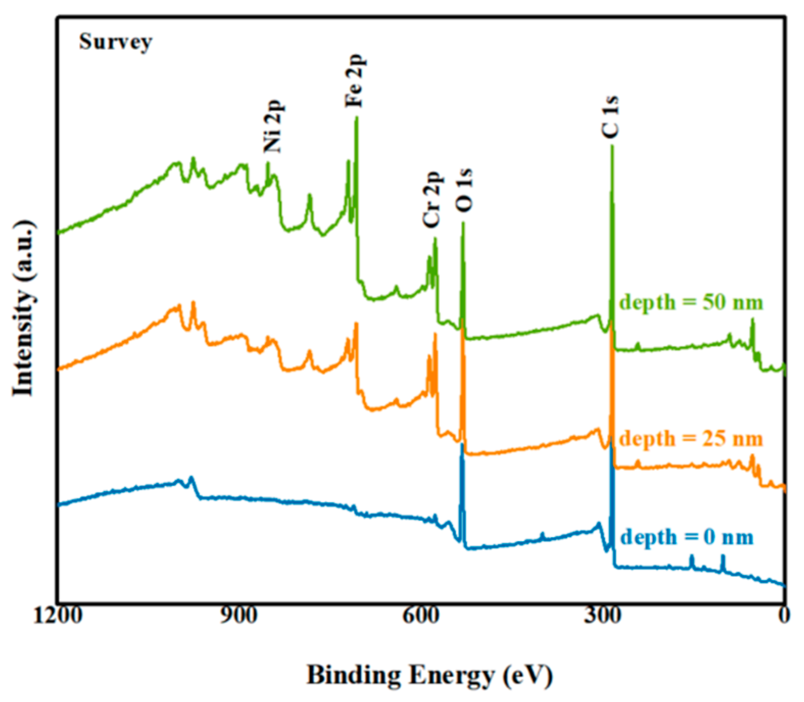
3.4.2. X-ray Energy Spectrum Analysis of Metal Joint Surfaces

To further investigate the laser direct joining mechanism between stainless steel and PCCF30, XPS was employed to analyze the interface elements on the surface of the stainless steel after tensile testing. The purpose of this analysis was to examine the presence of chemical bonds at the joint interface. The experimental sample consisted of stainless steel after tensile testing under the following connection process parameters: laser joining power of 650 W, laser joining speed of 10 mm/s, texture spacing of 0.3 mm, texture scanning count of 10 times, and PET interlayer thickness of 0.05 mm.
Due to the heavy presence of residual polymer on the surface of the stainless steel sample and the limited scanning depth of 3~4 nm in the XPS equipment, Ar+ etching was applied to the sample surface during the experiment. The etching process was performed twice, with each etching cycle reaching a depth of 25 nm.
(1)
Comparison of low-magnification, full-spectrum maps at different etching depths on the surface of stainless steel
A comparison of low-magnification, full-spectrum maps at different etching depths on the surface of stainless steel is presented in Figure 12. The primary detection elements were C and O in PCCF30, as well as Cr on the stainless steel surface. It is apparent from the figure that in the absence of etching, the main elements detected were C and O, indicating the presence of residual polymer on the stainless steel surface. However, when the etching depth reached 50 nm, clear signals of Cr and Fe were detected, suggesting the identification of the interface between the stainless steel and the polymer.
(2)
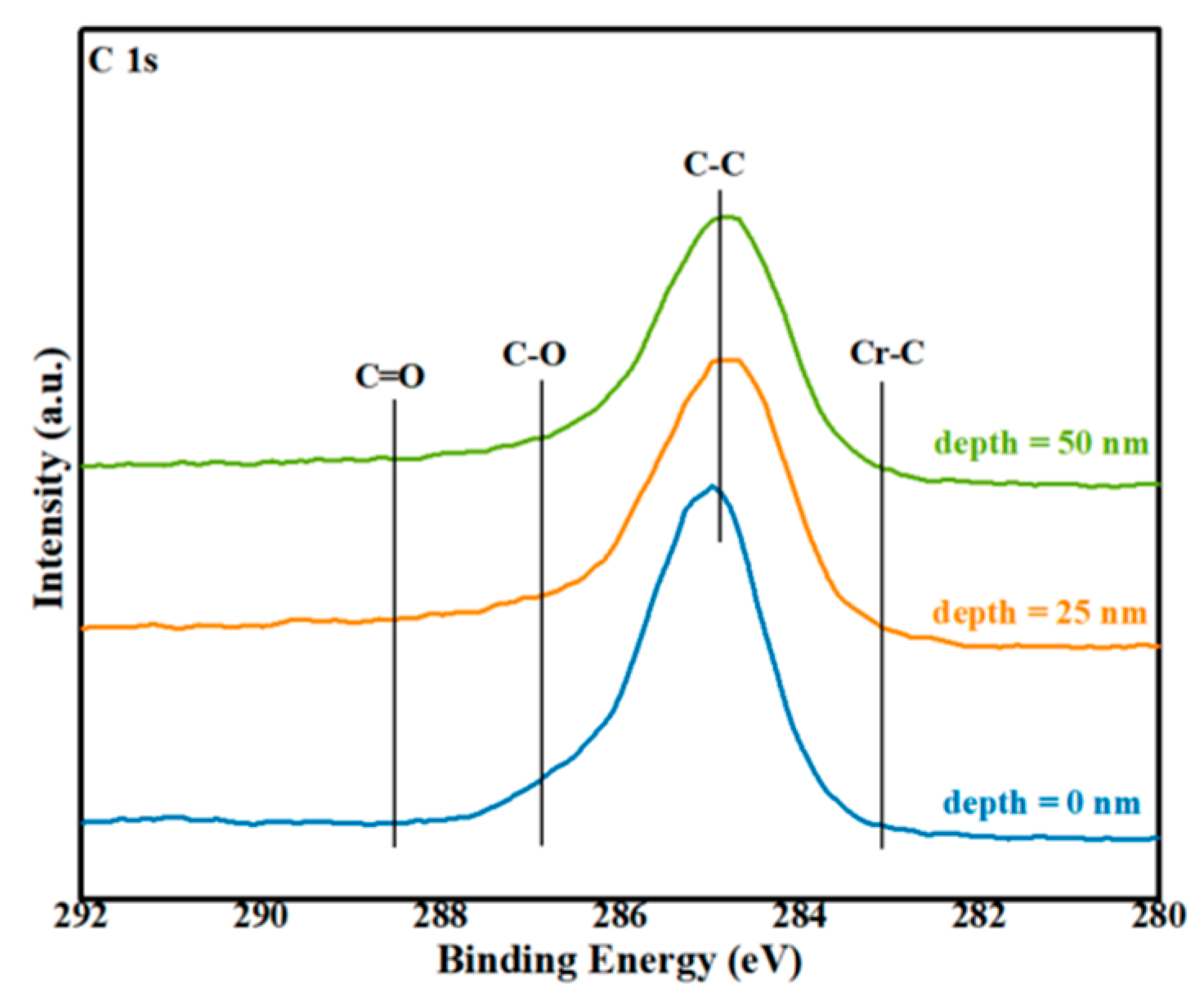
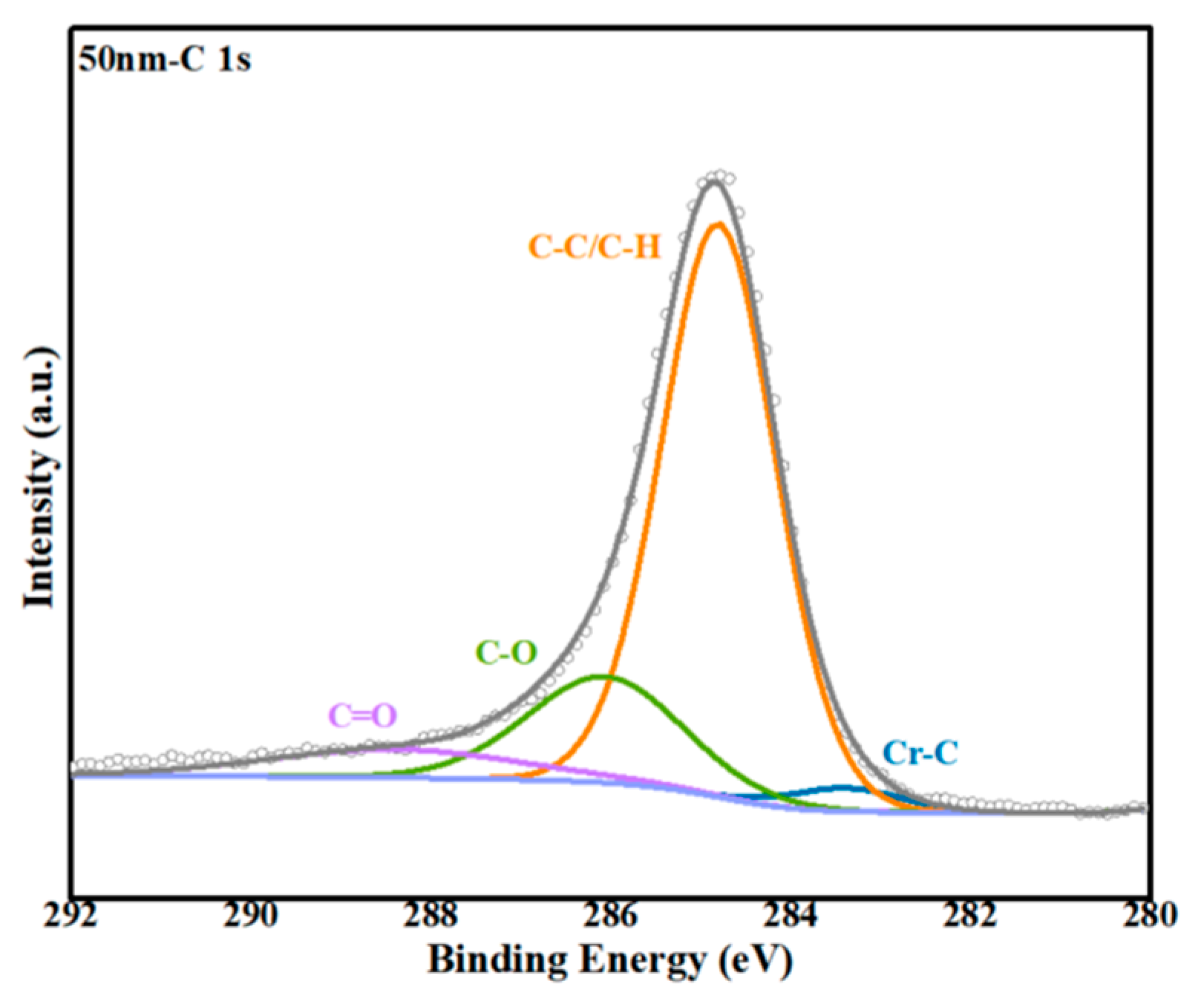
Analysis of the C1s line at different etching depths on the surface of stainless steel
Additionally, the high-magnification energy spectra of the C1s line at various etching depths on the stainless steel surface after tensile testing are displayed in Figure 13. The peaks related to the C–C interactions within the polymer were detected near 284.8 eV. At an etching depth of 50 nm, a new peak emerged at a binding energy of 283.39 eV, signifying the formation of a Cr–C chemical bond, based on previous studies [29] and analysis from the NIST spectral database [31]. Figure 14 shows the high-magnification peak separation spectrum at an etching depth of 50 nm.
(3)
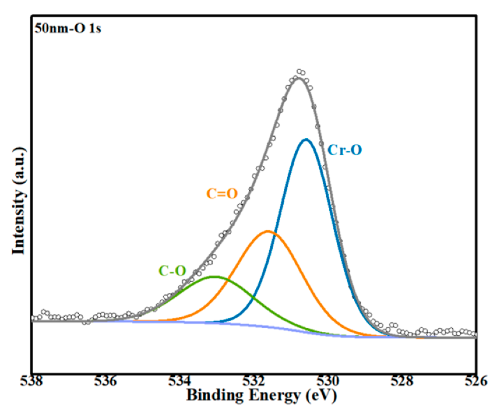
Analysis of the O1s line at different etching depths on the surface of stainless steel
The high-magnification energy spectra of the O1s line at different etching depths on the stainless steel surface after tensile testing are shown in Figure 15. The O1s peak detected before etching primarily originated from C–O and C=O bonds within the residual polymer on the stainless steel surface. As the etching depth increased, the amount of polymer on the stainless steel surface gradually decreased. At an etching depth of 50 nm, the signal peak near a binding energy of 532.29 eV weakened steadily, while a new signal peak emerged at a binding energy of approximately 530.69 eV. According to previous studies [29] and an analysis from the NIST spectral database [31], it can be inferred that a Cr–O chemical bond formed at a binding energy of 530.69 eV. Figure 16 shows the high-magnification peak separation spectrum at an etching depth of 50 nm.
(4)
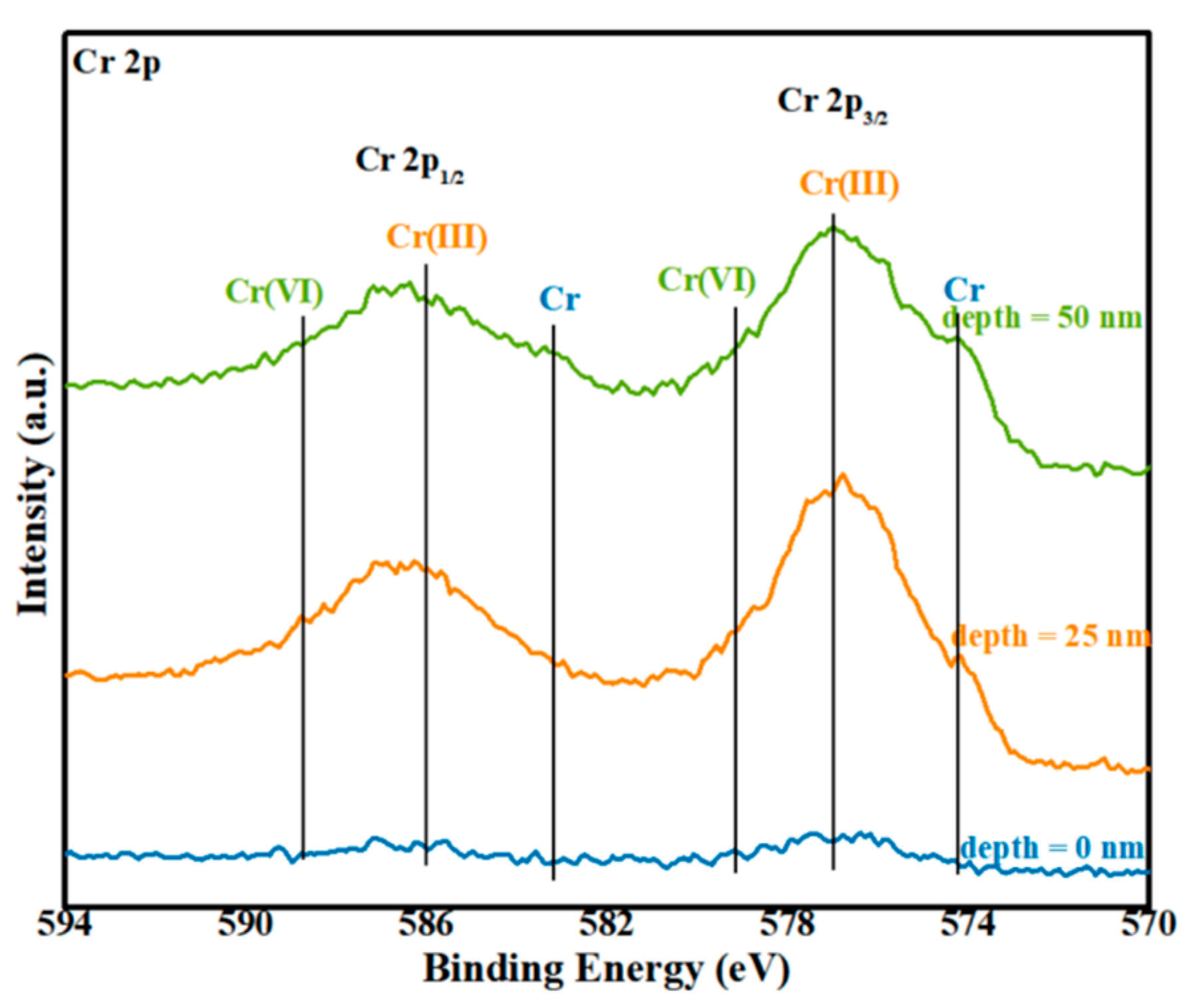
Analysis of the Cr2p line at different etching depths on the surface of stainless steel
Finally, the analysis of the Cr2p line at different etching depths on the surface of stainless steel is discussed.
The high-magnification energy spectra of the Cr2p line at various etching depths on the surface of stainless steel after tensile testing are displayed in Figure 17. From the figure, it is evident that the signal of Cr was weak when no etching was performed. This is attributed to the presence of residual polymer on the stainless steel surface, with some Cr penetrating the polymer. As the etching depth increased, Cr2O3 signals were detected at binding energies of 576.69 eV and 586.22 eV, while the peak positions at 574.47 eV and 583.63 eV corresponded to the split orbitals of Cr 3/2p and 1/2p, respectively. The appearance of signals near 579.36 eV and 578.98 eV indicated the formation of Cr–O–C chemical bonds, as supported by previous research [30,32] and the NIST spectral database [31], as well as the analyses of the C1s and O1s orbitals. The peak separation spectrum at an etching depth of 50 nm is presented in Figure 18.
Based on the aforementioned XPS data analysis, it can be concluded that the incorporation of a PET film and surface texture treatment on stainless steel effectively enhance the bonding strength of the joint by forming Cr–O–C chemical bonds between the PET interlayer and the upper layer of the stainless steel.

4. Conclusions

(1)
Among the three textured patterns tested, the combination of vertical lines and waves yielded the highest shear strength in the connection between the stainless steel and PCCF30 after surface texture treatment. A smaller texture spacing resulted in a higher joint shear strength; however, an excessively small spacing caused surface ablation of the stainless steel. Increasing the texture scanning count gradually increased the maximum depth of the grooves on the stainless steel surface but decreased the width of the grooves, which hindered the flow of the molten polymer and diminished the anchoring effect of the joint. Therefore, an appropriate texture spacing and scanning count were crucial for achieving optimal shear strength in the joint connection.
(2)
The shear strength of the joint decreased progressively with increasing interlayer thickness. For a texture spacing of 0.3 mm, a texture scanning count of 10, and a PET interlayer thickness of 0.05 mm, the joint shear strength reached a maximum value of 11.85 MPa, which was nine times greater than that of direct joining. This demonstrates that surface texture pretreatment and the addition of a PET interlayer significantly enhance the shear strength of the joint.
(3)
The addition of a PET interlayer in conjunction with surface texture pretreatment improved the flowability of the molten polymer. This in turn enhanced the mechanical anchoring effect of the joint and resulted in improved joint shear strength.
(4)
XPS analysis of the interface at the joint between stainless steel and PCCF30, subsequent to surface texture treatment and the addition of a PET interlayer, revealed the presence of a substantial amount of residual polymer on the metal surface. Following etching, the formation of Cr–O–C chemical bonds between PET and the upper layer of the stainless steel (304 stainless steel) was confirmed. This significant development led to a considerable increase in the connection strength of the joint.

Author Contributions

Formal analysis, H.C., H.L., Z.S. and X.W.; investigation, H.C. and X.W.; data curation, H.C., H.L. and X.W.; writing—original draft preparation, H.C.; conceptualization, X.W. and Z.S.; methodology, H.C. and H.L.; supervision, X.W. All authors have read and agreed to the published version of the manuscript.

Funding

This research received no external funding.

Data Availability Statement

The raw data supporting the conclusions of this article will be made available by the authors on request.

Conflicts of Interest

The authors declare no conflicts of interest.

References

  1. Feng, Z.W.; Zhou, B.S.; Zhang, T. Investigation on Laser Direct Joining of Aluminum Alloy-CF/PA66 and Chemical Bonding Mechanism. Chin. J. Lasers. 2022, 49, 48–56. [Google Scholar]
  2. Hu, L.; Feng, P.; Gao, W. Flexural behavior of light steel purlins reinforced by prestressed CFRP laminates. Thin Walled Struct. 2022, 174, 109125. [Google Scholar] [CrossRef]
  3. Jiang, H.; Ji, Y.; Hu, Y. Interfacial design and flexural property of CFRP/aluminum-honeycomb sandwich with Aramid-pulp micro/nano-fiber interlays. Compos. Struct. 2022, 289, 115486. [Google Scholar] [CrossRef]
  4. Zhan, Y.P.; Kong, L.Z.; Lu, W. Electrochemical Studies on Corrosion Behaviors of 304 Stainless Steel Welded Joints in Concentrated Sulfuric Acid. Mater. Prot. 2017, 50, 15–18. [Google Scholar]
  5. Zhang, W.; Liu, F.; Liu, L. Effect of grain size and distribution on the corrosion behavior of Y2O3 dispersion-strengthened 304 stainless steel. Mater. Today Commun. 2022, 31, 103723. [Google Scholar] [CrossRef]
  6. Meng, X.C. Joint formation and joining mechanism of FSW between CF/PEEK composite and 2060-T8 aluminum alloy. Harbin Harbin Inst. Technol. 2020, 112, 328–336. [Google Scholar]
  7. Wang, H.P.; Yan, P.; Ding, X.L. Enhanced laser direct joining of continuous carbon fiber reinforced polyetheretherketone and titanium alloy with controllable mechanical interlocks. J. Manuf. Process. 2023, 86, 56–65. [Google Scholar] [CrossRef]
  8. Cao, C.X. One Generation of Material Technology, One Generation of Large Aircraft. Acta Aeronaut. Et Astronaut. Sin. 2008, 29, 701–706. [Google Scholar]
  9. Lambiase, F.; Paoletti, A. Mechanical behavior of AA5053/polyetheretherketone (PEEK) made by friction assisted joining. Compos. Struct. 2018, 189, 70–78. [Google Scholar] [CrossRef]
  10. Agostini, M.; Greco, G.; Cecchini, M. Polydimethylsiloxane (PDMS) irreversible bonding to untreated plastics and metals for microfluidics applications. APL Mater. 2019, 7, 081108. [Google Scholar] [CrossRef]
  11. Chen, B.; Jiang, X.; Min, J.Y. Effect of surface topography on mechanical properties of steel-polycarbonate joints by laser direct joining. Weld. World 2022, 66, 1811–1823. [Google Scholar] [CrossRef]
  12. Lambiase, F.; Paoletti, A.; Grossi, V. Improving energy efficiency in friction assisted joining of metals and polymers. J. Mater. Process. Technol. 2017, 250, 379–389. [Google Scholar] [CrossRef]
  13. Pan, R.; Deng, Y.H.; Zhang, H. Thermal self-pressure diffusion connection and mechanism analysis of TC4 titanium alloy under rigid confinement by local induction heating. Rare Met. Mater. Eng. 2021, 50, 373–379. [Google Scholar]
  14. Toshiaki, Y.; Hirofumi, S.; Masahiro, F. Effect of anodic oxide layer on friction stir spot welding between anodized A5052 and CFRTP. Weld. Int. 2024, 38, 430–440. [Google Scholar]
  15. Fan, S.; Yuan, M.; Xu, J. Nondestructive evaluation of bonding quality of dual-layer coatings based on the multi-feature ultrasonic method. Appl. Acoust. 2024, 224, 110151. [Google Scholar] [CrossRef]
  16. Liu, L.; Wang, G.; Zhang, J. Synchronous optimization of surface flatness and interfacial bonding strength in laser cladding by Marangoni flow. J. Manuf. Process. 2024, 125, 25–37. [Google Scholar] [CrossRef]
  17. Jung, D.J.; Cheon, J.; Na, S.-J. Effect of surface pre-oxidation on laser assisted joining of acrylonitrile butadiene styrene (ABS) and zinc-coated steel. Mater. Des. 2016, 99, 1–9. [Google Scholar] [CrossRef]
  18. Feng, Y.; Pan, R.; Zhao, T. Direct joining of quartz glass and copper by nanosecond laser. Ceram. Int. 2023, 49, 36056–36070. [Google Scholar]
  19. Wang, Q.; Fu, R.; Wang, F. Effect of Temperature Distribution on Interfacial Bonding Process between CFRTP Composite and Aluminum Alloy during Laser Direct Joining. Appl. Sci. 2023, 13, 11973. [Google Scholar] [CrossRef]
  20. Kim, S.W.; Park, T.; Um, M.K. Effect of caprolactam modified phenoxy-based sizing material on reactive process of carbon fiber-reinforced thermoplastic polyamide-6. Compos. Part A 2020, 139, 106104. [Google Scholar] [CrossRef]
  21. Lambiase, F.; Genna, S. Laser-assisted direct joining of AISI304 stainless steel with polycarbonate sheets: Thermal analysis, mechanical characterization, and bonds morphology. Opt. Laser Technol. 2017, 88, 205–214. [Google Scholar] [CrossRef]
  22. Kumar, S.B.; Sridhar, I.; Sivashanker, S. Tensile failure of adhesively bonded CFRP composite scarf joints. Mater. Sci. Eng. B 2006, 132, 113–120. [Google Scholar] [CrossRef]
  23. Kolesnikov, B.; Herbeck, L.; Fink, A. CFRP/titanium hybrid material for improving composite bolted joints. Compos. Struct. 2008, 83, 368–380. [Google Scholar] [CrossRef]
  24. Amancio-Filho, S.T.; Dos Santos, J.F. Joining of polymers and polymer-metal hybrid structures: Recent developments and trends. Polym. Eng. Sci. 2009, 49, 1461–1476. [Google Scholar] [CrossRef]
  25. Bi, J.L.; Zhang, Y.J. Effect of Processing Fluidity on Properties of PC Resin. Shandong Chem. Ind. 2020, 49, 54–56. [Google Scholar]
  26. Su, W.F. PET/PC Research on Blending and In-situ Fiber Formation of Composite Materials; Donghua University: Shanghai, China, 2010. [Google Scholar]
  27. Miyashita, Y.; Takahashi, M.; Takemi, M. Dissimilar materials micro welding between stainless steel and plastics by using pulse YAG laser. J. Solid Mech. Mater. Eng. 2009, 3, 409–415. [Google Scholar] [CrossRef]
  28. Naat, N.; Boutar, Y.; Naïmi, S.; Mezlini, S.; Da Silva, L.F.M. Effect of surface texture on the mechanical performance of bonded joints: A review. J. Adhes. 2023, 99, 166–258. [Google Scholar] [CrossRef]
  29. Katayama, S.; Kawahito, Y. Laser direct joining of metal and plastic. Scr. Mater. 2008, 59, 1247–1250. [Google Scholar] [CrossRef]
  30. Farazila, Y.; Miyashita, Y.; Mutoh, Y. Effect of anodizing on pulsed Nd:YAG laser joining of polyethylene terephthalate (PET) and aluminium alloy (A5052). Mater. Des. 2012, 37, 410–415. [Google Scholar]
  31. National Institute of Standards and Technology [EB/OL]. Retrieve Data for a Selected Element. Available online: https://srdata.nist.gov/xps/EnergyTypeElement (accessed on 23 November 2023).
  32. Tan, X.H.; Shan, J.; Ren, J. Effects of Cr Plating Layer On Shear Strength and Interface Bonding Characteristic of Mild Steel/CFRP Joint by Laser Heating. Acta Metall. Sin. 2013, 49, 751–756. [Google Scholar] [CrossRef]
Figure 1. Schematic diagram of pretreatment of stainless steel surface texture.
Metals 14 00924 g001
Figure 2. Schematic diagram of laser direct joining: (a) texture treatment; (b) texture treatment and adding intermediate layer.
Metals 14 00924 g002
Figure 3. Effect of different texture types on joint strength.
Metals 14 00924 g003
Figure 4. Surface morphology of stainless steel under different texture scanning times.
Metals 14 00924 g004
Figure 5. Cross-sectional morphology of grooves corresponding to different scan times.
Metals 14 00924 g005
Figure 6. Effect of different texture scanning times on the geometric size of grooves: (a) texture width; (b) texture depth.
Metals 14 00924 g006
Figure 7. Joint cross section morphologies, corresponding to different texture scanning times.
Metals 14 00924 g007
Figure 8. Joint strength of different pretreatments under different connection powers.
Metals 14 00924 g008
Figure 9. Appearance of joints after various pretreatments.
Metals 14 00924 g009
Figure 10. Micromorphology of the joint cross section under different laser connection powers.
Metals 14 00924 g010
Figure 11. Added interlayers of different thicknesses, corresponding to the joint cross section morphology.
Metals 14 00924 g011
Figure 12. Low-magnification XPS spectra at different etching depths.
Metals 14 00924 g012
Figure 13. High-rate energy spectra of C1s at different etching depths.
Metals 14 00924 g013
Figure 14. High-magnification energy spectrum of C1s at an etching depth of 50 nm.
Metals 14 00924 g014
Figure 15. High-magnification O1s spectra at different etching depths.
Metals 14 00924 g015
Figure 16. High-magnification energy spectrum of O1s at an etching depth of 50 nm.
Metals 14 00924 g016
Figure 17. High-rate energy spectra of Cr2p corresponding to different etching depths.
Metals 14 00924 g017
Figure 18. High-rate energy spectra of Cr2p at an etching depth of 50 nm.
Metals 14 00924 g018
Disclaimer/Publisher’s Note: The statements, opinions and data contained in all publications are solely those of the individual author(s) and contributor(s) and not of MDPI and/or the editor(s). MDPI and/or the editor(s) disclaim responsibility for any injury to people or property resulting from any ideas, methods, instructions or products referred to in the content.

