
Development and Characterisation of a New Die-Casting Die Cooling System Based on Internal Spray Cooling


Abstract
1. Introduction
2. Theoretical Background and Methods for Describing Spray Cooling
2.1. Influencing Factors on the Heat Transfer of a Spray Cooling
2.2. Characterisation of the Spray Flow
2.3. Temperature Change Rates
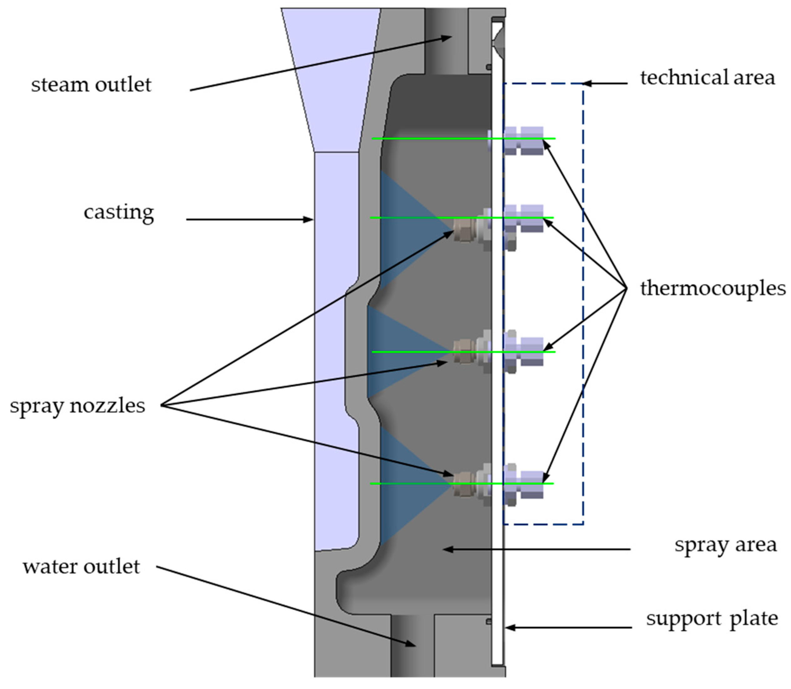
3. Development of a Masked Mould with Internal Spray Cooling
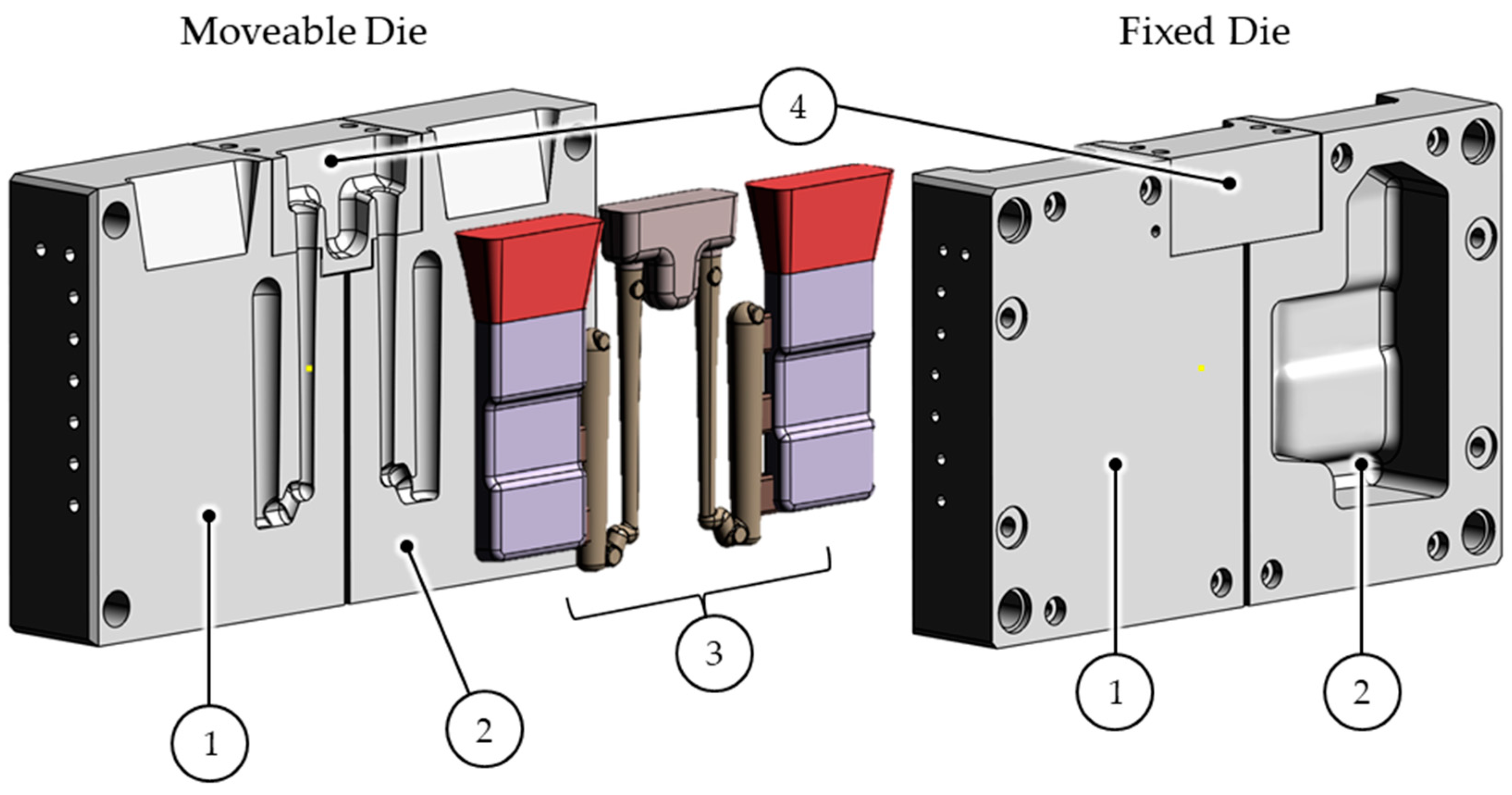
3.1. Conception of the Experiment Mould and Design of the Casting
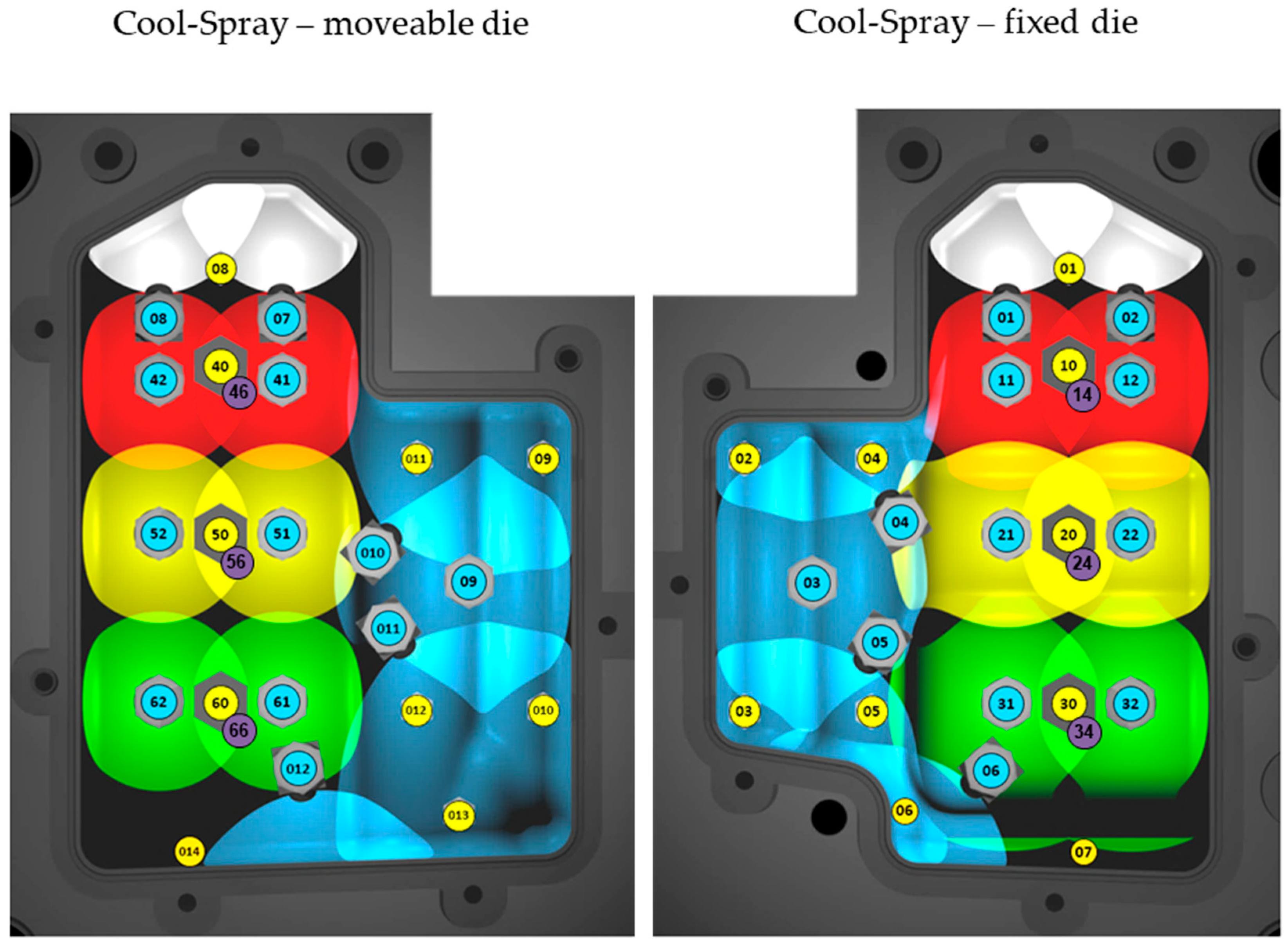
3.2. Design of the Cooling Systems
3.3. Simulation Workflow
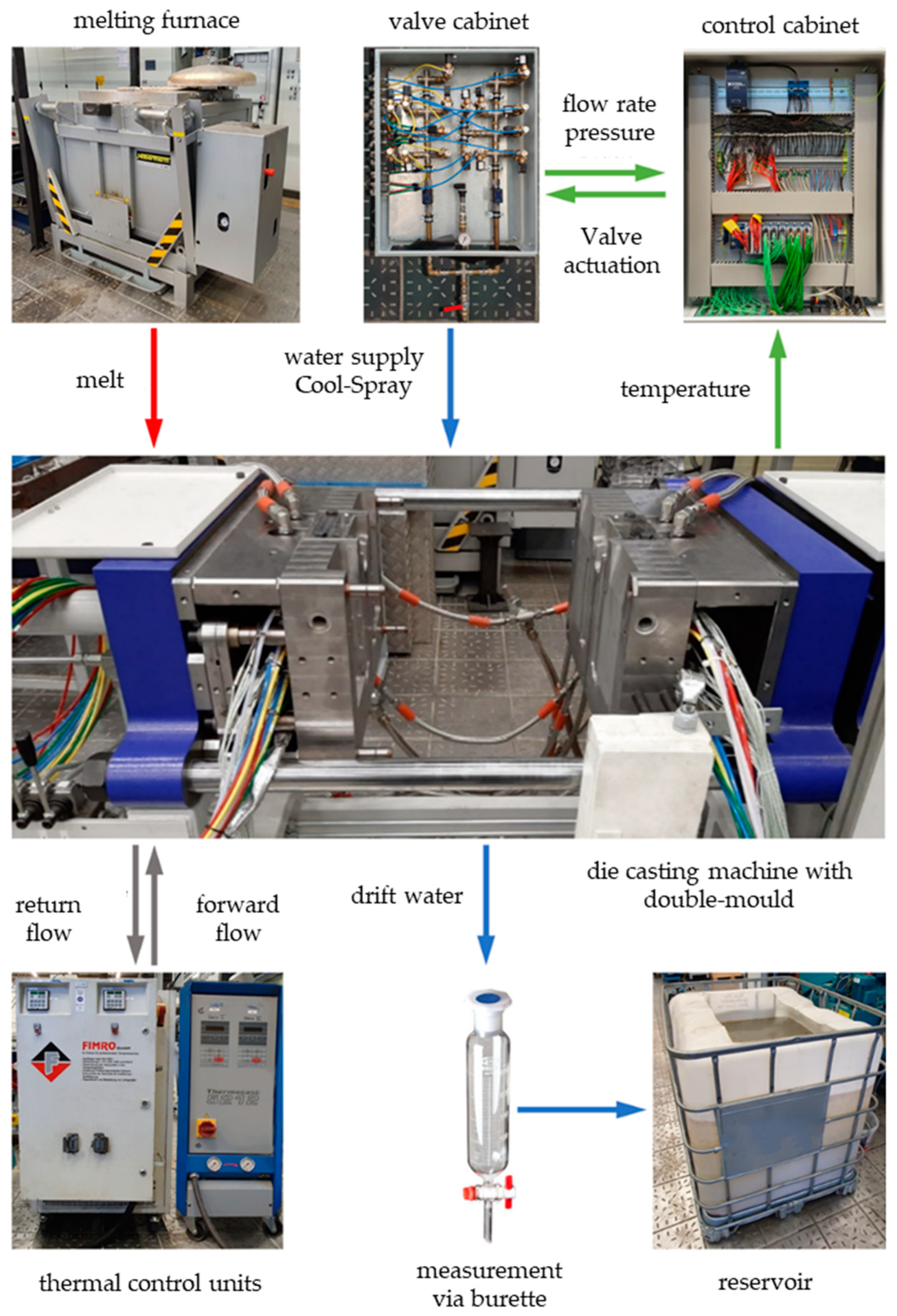
3.4. Integration of Spraying and Measuring Technology
4. Experimental Setup and Test Procedure
5. Results and Discussion
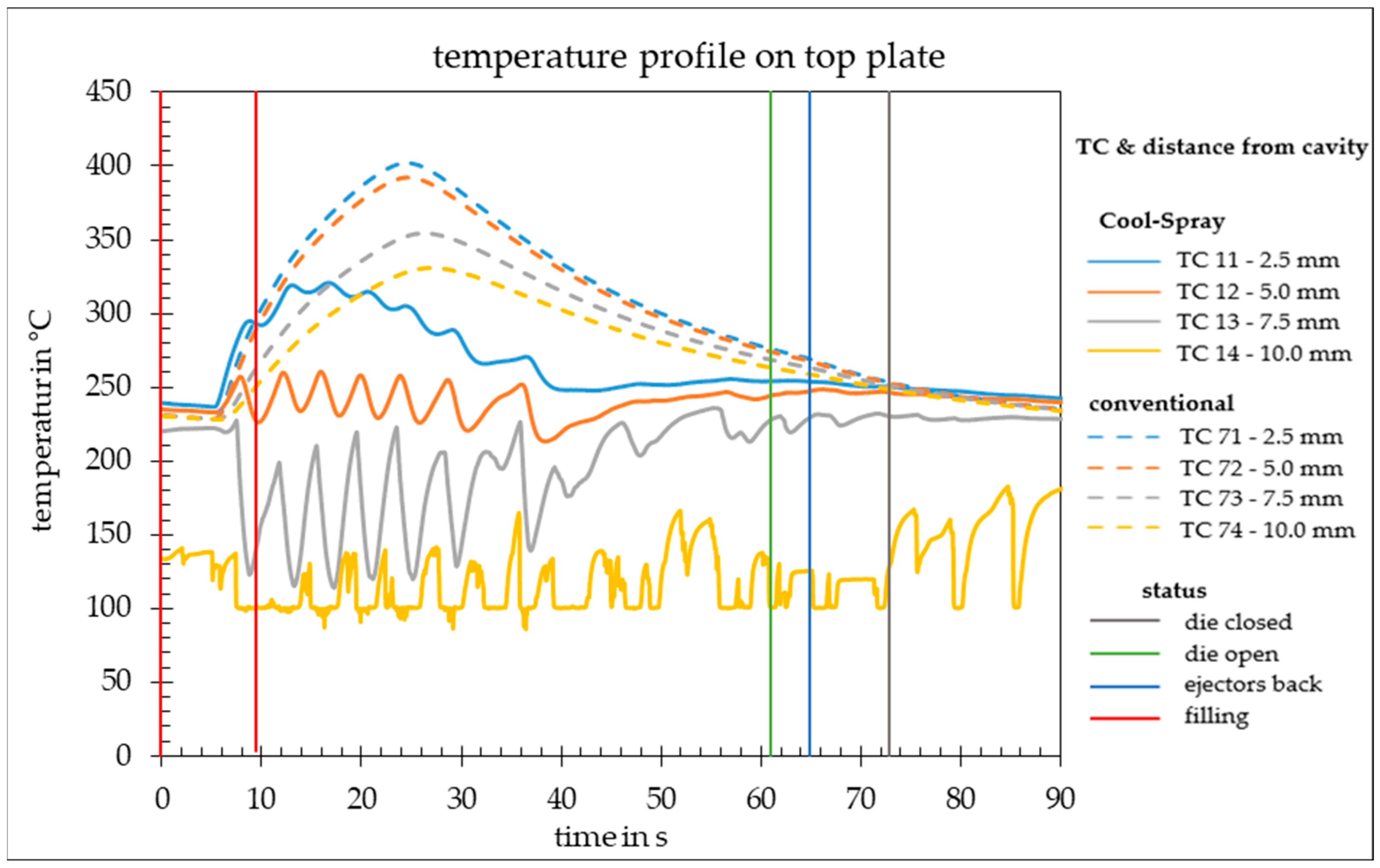
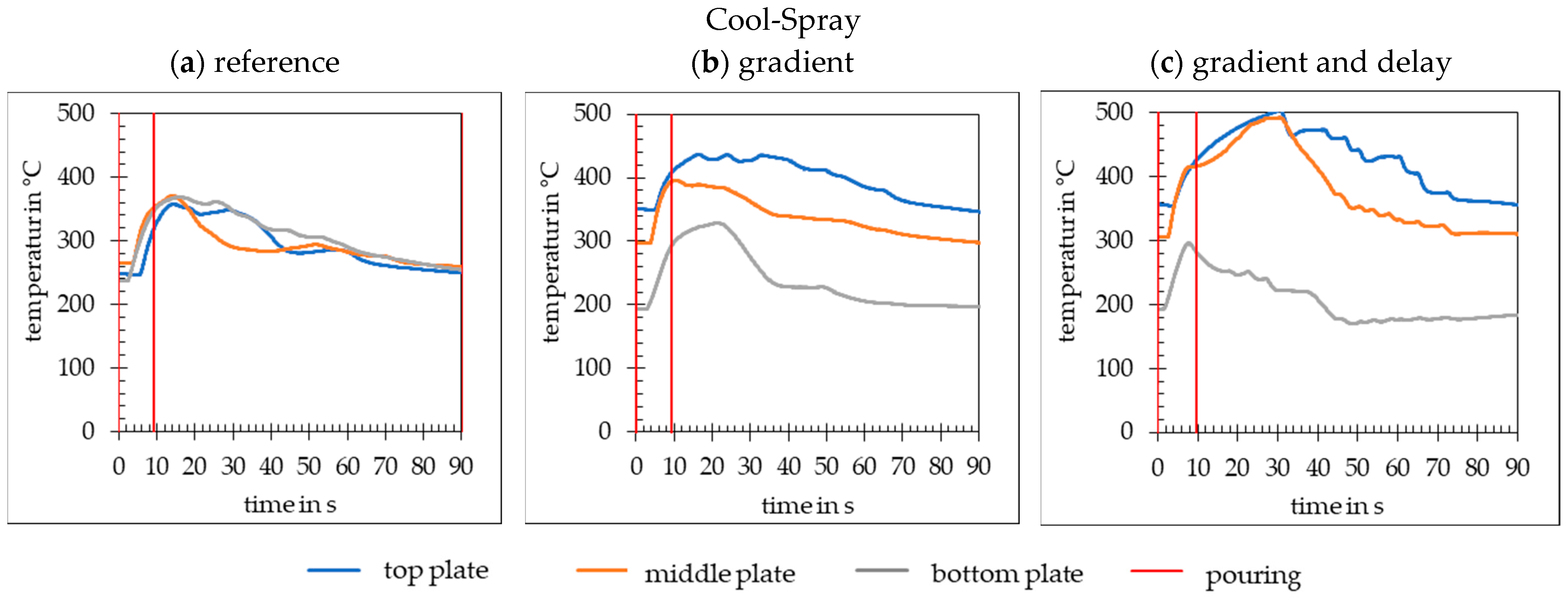
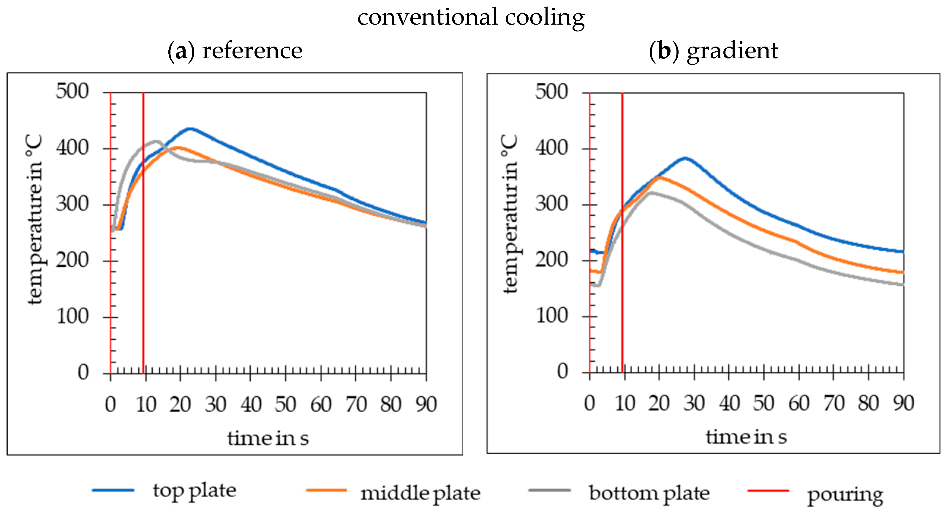
5.1. Analysis of the Tempering and Reaction Behaviour of the Mould
5.2. Temperature Change Rates
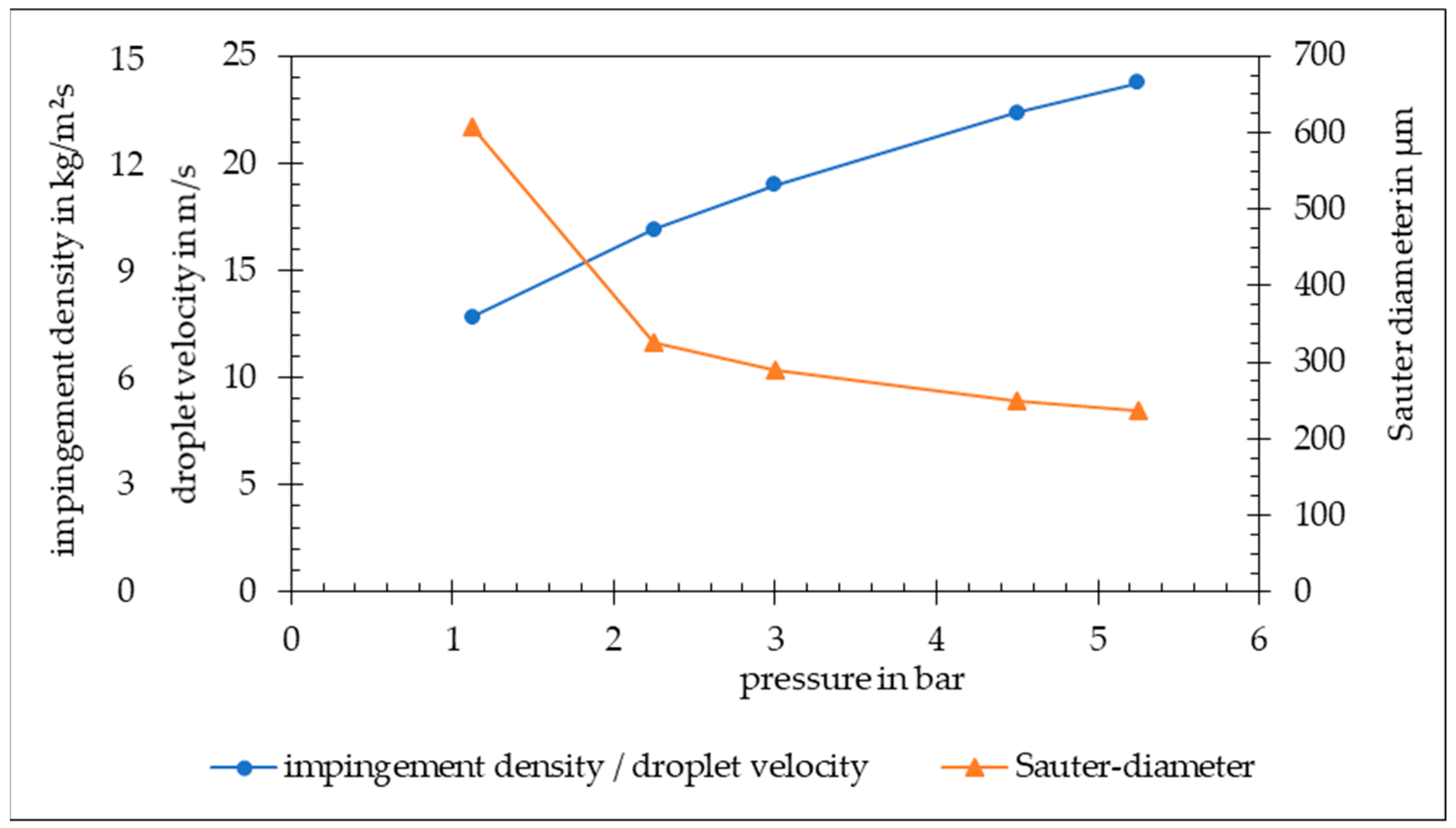
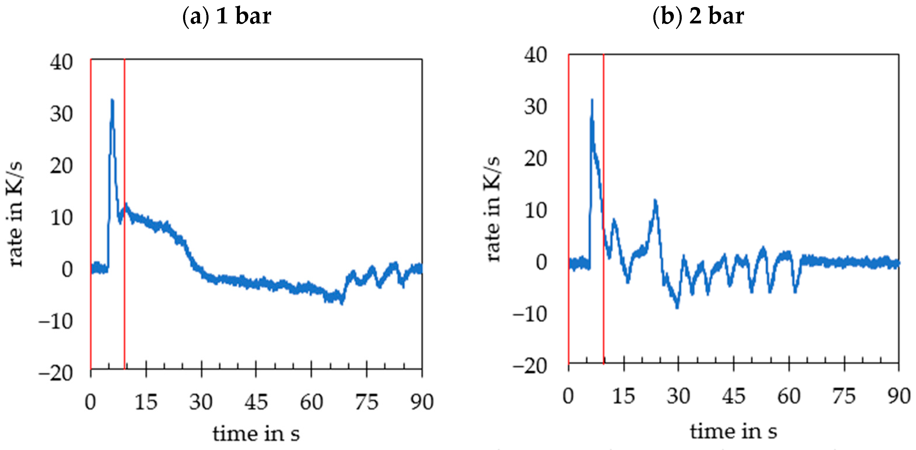
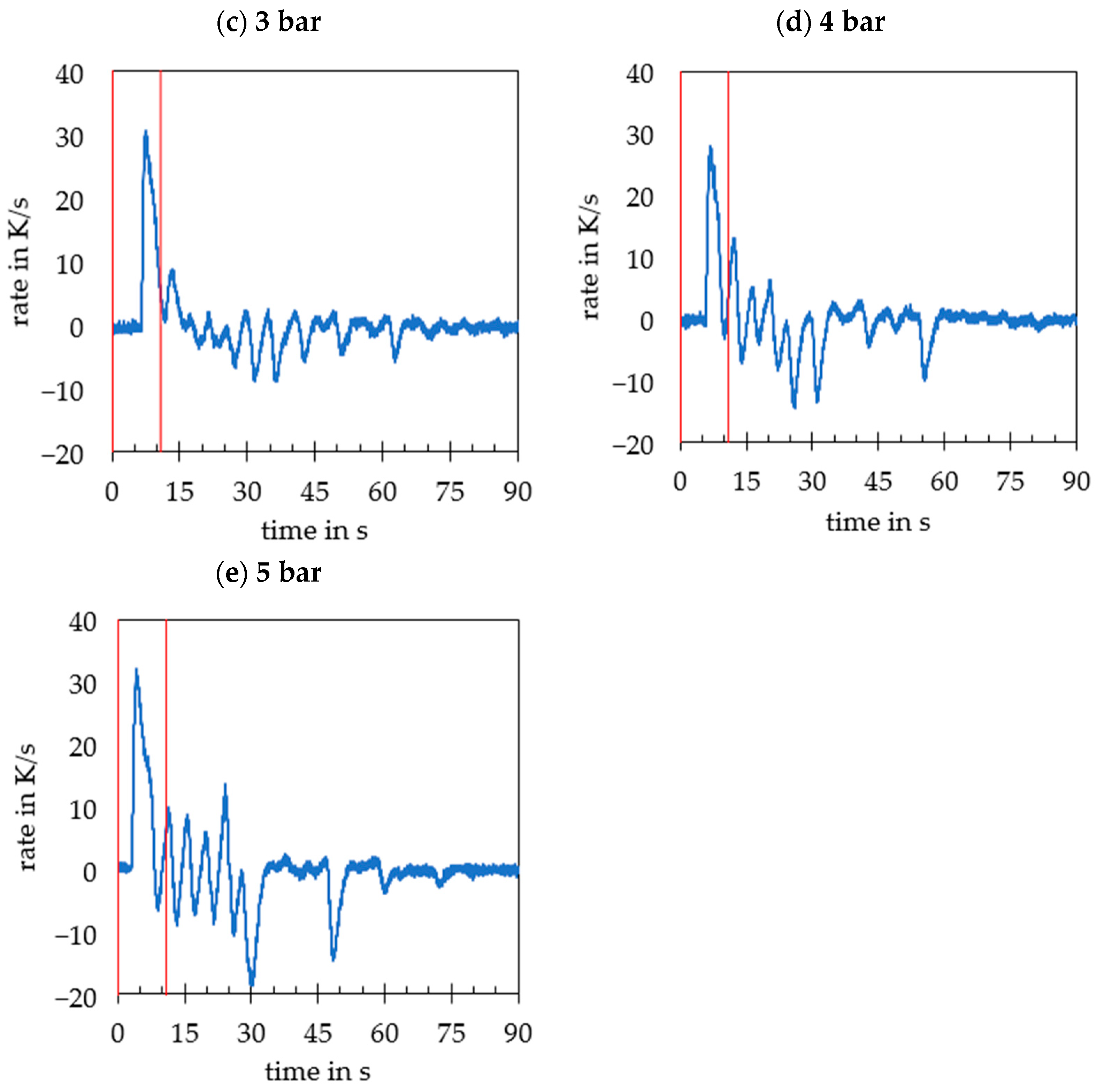
5.2.1. Temperature Change Rates as a Function of Pressure for Cool-Spray
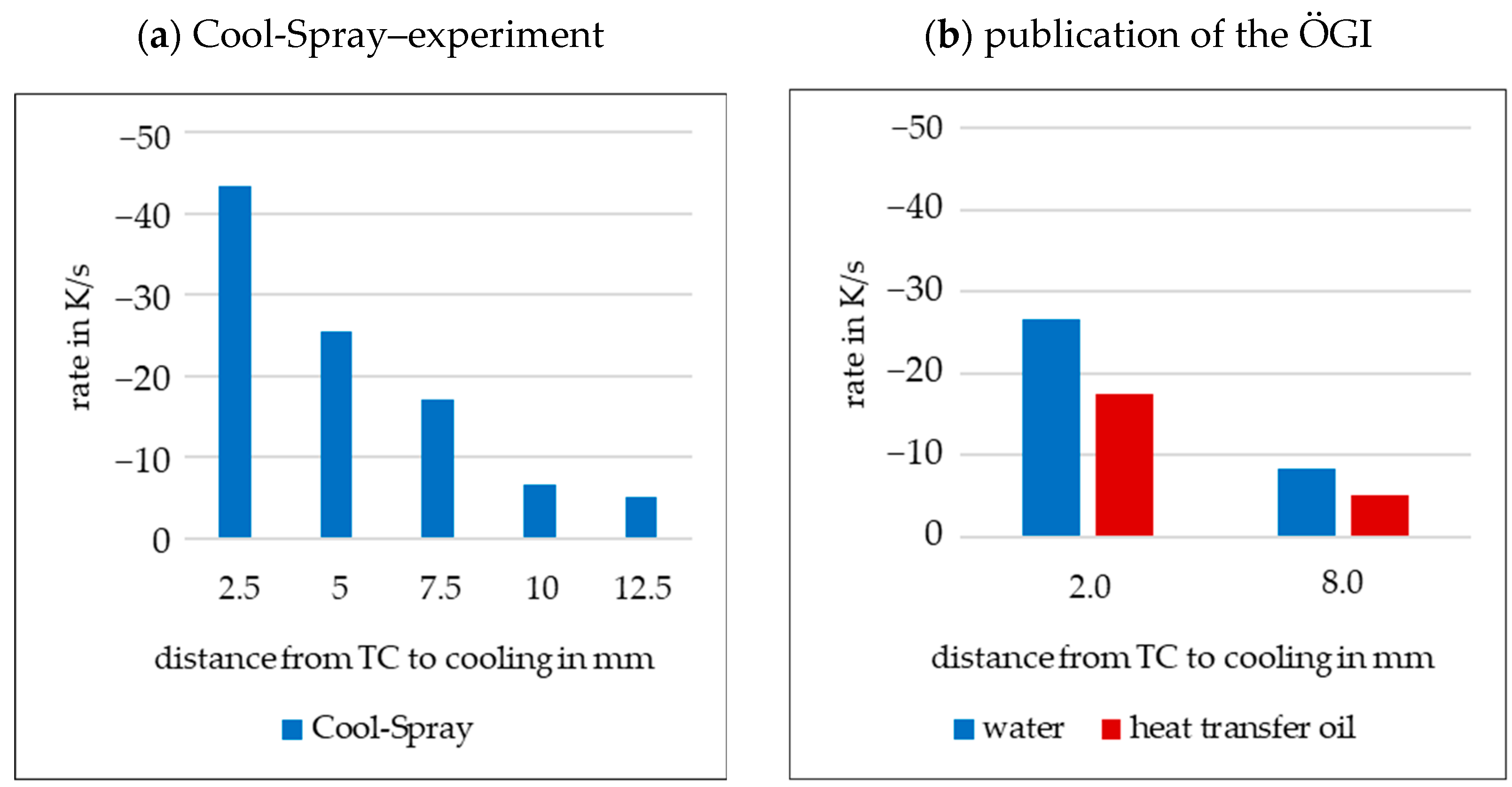
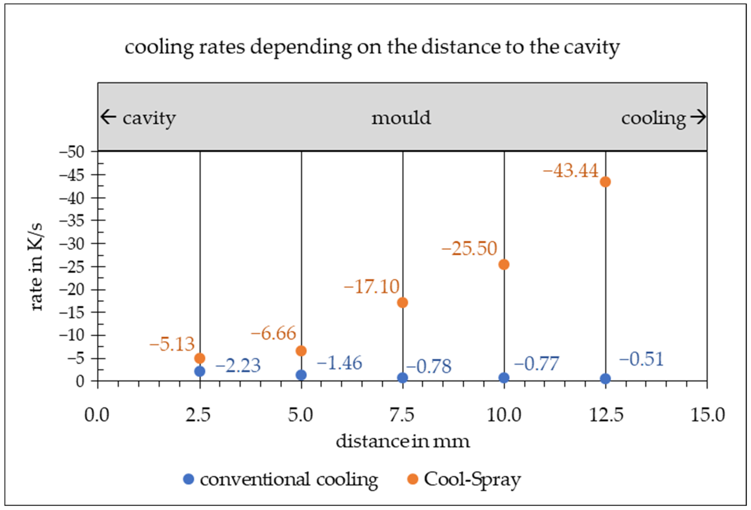
5.2.2. Analysis of the Cooling Performance
5.2.3. Comparison with Conventional Cooling
5.3. Influenceability of Component Quality
6. Conclusions
Author Contributions
Funding
Data Availability Statement
Conflicts of Interest
References
- The European Parliament and the Council of the European Union. Regulation (EU) 2021/1119 of the European Parliament and of the Council of 30 June 2021 Establishing the Framework for Achieving Climate Neutrality and Amending Regulations (EC) No 401/2009 and (EU) 2018/1999 (‘European Climate Law’); European Parliament: Brüssel, Belgium, 2021. [Google Scholar]
- Nogowizin, B. Theorie und Praxis des Druckguss; Schiele & Schön: Berlin, Germany, 2011; pp. 643–644. [Google Scholar]
- Liu, M.; Sang, B.; Hao, C.; Chen, G.; Yan, J. Thermal fatigue life prediction method for die casting mold steel based on the cooling cycle. J. Mater. Process. Technol. 2023, 321, 118131. [Google Scholar] [CrossRef]
- Majerník, J.; Podaril, M.; Majernikova, M. Evaluation of High Pressure Die Casting Mold Temperature Relations Depending on the Location of the Tempering Channels. Arch. Foundry Eng. 2024, 24, 115–120. [Google Scholar] [CrossRef]
- Piekło, J.; Garbacz-Klempka, A.; Burbelko, A. The Numerical Fatigue Life Analysis of a Conformal HPDC Mould Core Additively Manufactured from Maraging Steel. Materials 2023, 16, 365. [Google Scholar] [CrossRef]
- Bharambe, C.; Jaybhaye, M.D.; Dalmiya, A.; Daund, C.; Shinde, D. Analyzing casting defects in high-pressure die casting industrial case study. Mater. Today Proc. 2023, 72, 1079–1083. [Google Scholar] [CrossRef]
- Brunhuber, E. Praxis der Druckgußfertigung, 4th ed.; Schiele & Schön: Berlin, Germany, 1991; pp. 11+30+367–384+408. ISBN 3-7949-0535-0. [Google Scholar]
- Glück, J.; Schilling, A. Efficiency and Agility of a Liquid CO2 Cooling System for Molten Metal Systems—Case Study. Therm. Eng. 2021, 28, 101485. [Google Scholar] [CrossRef]
- Nogowizin, B. Konstruktion und Fertigung der Druckgießformen; Schiele & Schön: Berlin, Germany, 2019; ISBN 978-3-7949-0893-6. [Google Scholar]
- Tucan, K.; Gschwandtner, R.; Hofer, P. Vergleich der Wirkung von Lokalen Temperiermaßnahmen in Druckgießformen. Giesserei-Rundschau 2012, 59, 8. [Google Scholar]
- Anand, A.; Nagarajan, D.; El Mansori, M.; Sivarupan, T. Integration of Additive Fabrication with High-Pressure Die Casting for Quality Structural Castings of Aluminium Alloys; Optimising Energy Consumption. Trans. Indian Inst. Met. 2023, 76, 347–379. [Google Scholar] [CrossRef]
- Kurtulus, K.; Bolatturk, A.; Coskun, A.; Gürel, B. An experimental investigation of the cooling and heating performance of a gravity die casting mold with conformal cooling channels. Appl. Therm. Eng. 2021, 194, 117105. [Google Scholar] [CrossRef]
- Andronov, V.; Pitrmuc, Z.; Zajíc, J. Conformal cooling as a support tool for eliminating local defects in high-pressure die casting series production. Prog. Addit. Manuf. 2024, 1–19. [Google Scholar] [CrossRef]
- Sode, M.; Kahlert, M.; Arold, T.; Fros, A.; Vollmer, M. Tailoring flow behavior and heat transfer in tempering channels for high-pressure die casting—Analysis of potentials of commercial static mixers and prospects of additive manufacturing. Int. J. Adv. Manuf. Technol. 2023, 125, 5463–5477. [Google Scholar] [CrossRef]
- Shin, S.; Lee, S.; Kim, D.; Lee, B. Enhanced cooling channel efficiency of high-pressure die-casting molds with pure copper linings in cooling channels via explosive bonding. J. Mater. Process. Technol. 2021, 297, 117235. [Google Scholar] [CrossRef]
- Reiche, L.; Nölke, O.; Fehlbier, M. Gussform. Patent DE 10 2014 001 563 B4, 20 August 2015. [Google Scholar]
- Reiche, L. Entwicklung einer Geregelten und Energieeffizienten Werkzeugtemperierung im Dauerformguss unter Einsatz einer Sprühkühlung mit Wärmerückgewinnung. Ph.D. Thesis, Universität Kassel, Kassel, Germany, 2019. [Google Scholar] [CrossRef]
- Findeisen, S. Zykluszeitreduzierung beim Druckgießen durch Mehrteiligen Werkzeugaufbau. Ph.D. Thesis, Technische Universität Bergakademie Freiberg, Freiberg, Germany, 2015; pp. 19–23. [Google Scholar]
- Haban, A.; Fehlbier, M.; Reiche, L. Umsetzung einer Gepulsten Verdampfungskühlung für Druckgusswerkzeuge im Serienprozess. In Gießen von Fahrwerks- und Karosseriekomponenten; VDI-Berichte: Bad Gögging, Germany, 2020; p. 131. ISBN 978-3-18-092367-3. [Google Scholar]
- Nukiyama, S. The Maximum and Minimum Values of the Heat Q Transmitted from Metal to Boiling Water under Atmospheric Pressure. J. Jpn. Soc. Mech. Eng. 1934, 37, 367–374. [Google Scholar] [CrossRef]
- Kim, J. Spray Cooling Heat Transfer: The State of the Art. Int. J. Heat Fluid Flow 2007, 28, 753–767. [Google Scholar] [CrossRef]
- Yang, J.; Chow, L.; Pais, M. Nucleate Boiling Heat Transfer in Spray Cooling. J. Heat Transf. 1996, 118, 668–671. [Google Scholar] [CrossRef]
- Aamir, M.; Qiang, L. Ultra Fast Spray Cooling and Critical Droplet Diameter Estimation from Cooling Rate. J. Power Energy Eng. 2014, 2, 259–270. [Google Scholar] [CrossRef]
- Somasundaram, S.; Tay, A. Comparative Study of Intermittent Spray Cooling in Single and Two Phase Regimes. Int. J. Therm. Sci. 2013, 74, 174–182. [Google Scholar] [CrossRef]
- Estes, K.; Mudawar, I. Correlation of Sauter Mean Diameter and Critical Heat Flux for Spray Cooling of Small Surfaces. Int. J. Heat Mass Transf. 1995, 38, 2985–2996. [Google Scholar] [CrossRef]
- Martínez-Galván, E.; Ramos, J. Film Thickness and Heat Transfer Measurements in a Spray Cooling System with R134a. J. Electron. Packag. 2011, 133, 1. [Google Scholar] [CrossRef]
- Liu, G.; Morsi, Y.; Clayton, B. Characterisation of the Spray Cooling Heat Transfer Involved in a High Pressure Die Casting Process. Int. J. Therm. Sci. 2000, 39, 582–591. [Google Scholar] [CrossRef]
- Todorov, T. Wärmeübergang bei der Sprühkühlung unter Berücksichtigung der Sprühstrahlparameter. Ph.D. Thesis, Otto-von-Guericke-Universität, Magdeburg, Germany, 2009; pp. 6+126. [Google Scholar]
- Aamir, M.; Qiang, L. Transient Heat Transfer Performance of Stainless Steel Structured Surfaces Combined with Air-Water Spray Evaporative Cooling at High Temperature Scenarios. Appl. Therm. Eng. 2017, 115, 418–434. [Google Scholar] [CrossRef]
- Hsieh, C.; Yao, S. Evaporative Heat Transfer Characteristics of a Water Spray on Micro-Structured Silicon Surfaces. Int. J. Heat Mass Transf. 2006, 49, 962–974. [Google Scholar] [CrossRef]
- Wengler, C. Einfluss des Heizwandmaterials auf den Wärmeübergang beim Blasensieden. Ph.D. Thesis, Universität Kassel, Kassel, Germany, 2018. [Google Scholar]
- Winter, M. Heat Transfer Mechanisms during Spray Cooling of Electronic Devices. Ph.D. Thesis, Technische Universität Darmstadt, Darmstadt, Germany, 2015. [Google Scholar]
- Deutsches Institut für Normung. DIN ISO 9276-2-Darstellung der Ergebnisse von Partikelgrößenanalysen–Teil 2: Berechnung von Mittleren Partikelgrößen/-Durchmessern und Momenten aus Partikelgrößenverteilungen; Beuth Verlag GmbH: Berlin, Germany, 2018; pp. 3–16. [Google Scholar]
- Nielsen, F. Gieß- und Anschnitttechnik—Grundlagen und Anwendung einer Methode; Gießereiverlag: Düsseldorf, Germany, 1993; pp. 2–37. [Google Scholar]
- Campbell, J. Complete Casting Handbook; Elsevier: Oxford, UK, 2015; pp. 741–852. [Google Scholar] [CrossRef]
- Erlenkämper, E. Der Beitrag des Spritzgießwerkzeuges zur Zykluszeit. Der Stahlformenbauer 2001, 18, 28–34. [Google Scholar]
- Lange-Robben, R. Beeinflussung des Wärmehaushalts metallischer Dauerformen. Ph.D. Thesis, Universität Hannover, Hannover, Germany, 2006; pp. 7–18. [Google Scholar]
- Ronté, V.; RoÓlSz, A. The Effect of Cooling Rate and Composition on the Secondary Dendrite Arm Spacing during Solidification. Part I: Al-Cu-Si Alloys. Int. J. Cast Met. Res. 2001, 13, 337–342. [Google Scholar] [CrossRef]
- Radhakrishna, K.; Seshan, S. Dendrite Arm Spacing and Mechanical Properties of Aluminium Alloy Castings. Cast Met. 1989, 2, 34–38. [Google Scholar] [CrossRef]
- Pavlovic-Krstic, J.; Bähr, R.; Krstic, G.; Putic, S. The Effect of Mould Temperature and Cooling Conditions on the Size of Secondary Dendrite Arm Spacing in Al-7Si-3Cu Alloy. Assoc. Metall. Eng. Serbia 2009, 15, 105–113. [Google Scholar]
- Cho, J.; Kim, C.; Choi, S.; Kang, C. The Relationship between Dendrite Arm Spacing and Cooling Rate of Al-Si Casting Alloys in High Pressure Die Casting. In Proceedings of the ICAA13 Pittsburgh, Pittsburgh, PA, USA, 3–7 June 2012; Weiland, H., Rollett, A.D., Cassada, W.A., Eds.; Springer: Cham, Switzerland, 2012. [Google Scholar] [CrossRef]
- Gössl, W. Untersuchung zur Kühlwirkung in Druckgussformen. Master’s Thesis, Montanuniversität Leoben, Leoben, Austria, 2011. [Google Scholar]
- Reichen, P.; Schwarz, M.; Altheimer, M. Characterizing the Cooling Capacity of Pulsed Air/Water Cooling in Die Casting Molds. In Proceedings of the Euroguss, Nuremberg, Germany, 16–18 January 2018. [Google Scholar]
- Bundesverband der Deutschen Gießerei-Industrie. Porositätsanalyse und -beurteilung mittels industrieller Röntgen-Computertomographie (CT). In Technical guideline P 203; BDG: Düsseldorf, Germany, 2019; Available online: https://www.guss.de/fileadmin/user_upload/richtlinien/bdg-richtlinie_p_203.pdf (accessed on 22 August 2024).


| Process Steps | Duration in s | Description |
|---|---|---|
| pouring | manually using a pouring ladle | |
| solidification | visual inspection of the solidification status | |
| die open | hydraulic and manual control | |
| ejection | hydraulic and manual control | |
| part removal | manual with foundry tongs | |
| return ejector | hydraulic and manual control | |
| die close | hydraulic and manual control | |
| waiting and preparation | scooping with a pouring laddle | |
| total cycle |
| Cool-Spray | Conventional Cooling | |
|---|---|---|
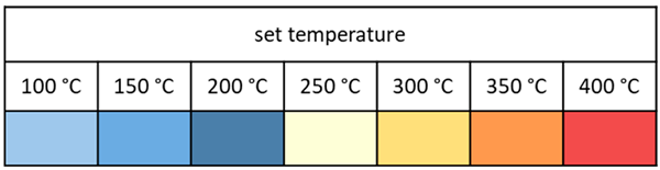
| set temperature | 250 °C | 200 °C |
| medium | water, 20 °C | heat transfer oil |
| flow rate | variable | 16–17 L/min |
| pressure | 4 bar | 5 bar |
| duty cycle | 20% | - |
| frequency | 5 Hz | - |
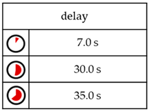
| (a) Reference | (b) Gradient | (c) Gradient and Delay | |
|---|---|---|---|
| Cool-Spray | 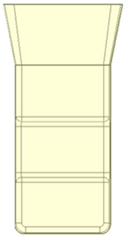 |  |  |
| conventional |  |  | - |
 |  | ||
Disclaimer/Publisher’s Note: The statements, opinions and data contained in all publications are solely those of the individual author(s) and contributor(s) and not of MDPI and/or the editor(s). MDPI and/or the editor(s) disclaim responsibility for any injury to people or property resulting from any ideas, methods, instructions or products referred to in the content. |
© 2024 by the authors. Licensee MDPI, Basel, Switzerland. This article is an open access article distributed under the terms and conditions of the Creative Commons Attribution (CC BY) license (https://creativecommons.org/licenses/by/4.0/).
Share and Cite
Haban, A.; Kracun, S.F.; Rohde, D.N.; Fehlbier, M. Development and Characterisation of a New Die-Casting Die Cooling System Based on Internal Spray Cooling. Metals 2024, 14, 956. https://doi.org/10.3390/met14090956
Haban A, Kracun SF, Rohde DN, Fehlbier M. Development and Characterisation of a New Die-Casting Die Cooling System Based on Internal Spray Cooling. Metals. 2024; 14(9):956. https://doi.org/10.3390/met14090956
Chicago/Turabian StyleHaban, Alexander, Stefanie Felicia Kracun, Danny Noah Rohde, and Martin Fehlbier. 2024. "Development and Characterisation of a New Die-Casting Die Cooling System Based on Internal Spray Cooling" Metals 14, no. 9: 956. https://doi.org/10.3390/met14090956
APA StyleHaban, A., Kracun, S. F., Rohde, D. N., & Fehlbier, M. (2024). Development and Characterisation of a New Die-Casting Die Cooling System Based on Internal Spray Cooling. Metals, 14(9), 956. https://doi.org/10.3390/met14090956