Article

Investigation of Properties in Magnesium Alloy Thin Plates after Die Casting Processes

Department of Mechanical Convergence Engineering, Hanyang University, Seoul 04763, Republic of Korea
*
Author to whom correspondence should be addressed.
These authors contributed equally to this work.
Metals 2024, 14(9), 970; https://doi.org/10.3390/met14090970
Submission received: 24 July 2024 / Revised: 16 August 2024 / Accepted: 21 August 2024 / Published: 27 August 2024
(This article belongs to the Special Issue Design, Processing and Characterization of Metals and Alloys)

Abstract

:
This study systematically analyzed the effect of design conditions on filling behavior and product characteristics when forming thin plates of magnesium alloy (AZ91D) of 0.5 mm or less using the die casting method. As a research method, a casting analysis simulation program was used to predict filling and solidification behavior under various process conditions. The molten metal injection temperature (610~670 °C), mold temperature (160~220 °C), and cooling water temperature (10~55 °C) were selected as key variables, and an analysis was performed for a total of five conditions. A simulation was conducted to analyze the charging speed distribution, location of oxides and bubbles, and solidification pattern. As a result of the study, the flow of molten metal in the low and high-speed sections of the plunger, uniformity of product thickness, and supply conditions of the molten metal were confirmed to be major factors. It is important to manage the molten metal injection temperature at an appropriate level to minimize product defects. Based on these conditions, a prototype was manufactured, the microstructure was observed, and a fine and uniform grain structure was observed in most areas. In mechanical property evaluation, superior physical properties were secured compared to existing bulk materials.

1. Introduction

Recently, as environmental regulations have strengthened and demands for improved energy efficiency, lightweight materials in transportation equipment, and miniaturization have increased. Accordingly, the demand for aluminum and magnesium alloys, which are lightweight materials, is greatly expanding. Magnesium alloys have the lowest density among practical metals but exhibit excellent specific strength, as shown in Table 1, and are attracting attention as next-generation lightweight structural materials [1,2,3,4,5].
Die casting is a process suitable for mass production of products with complex shapes. As one of the main manufacturing processes for magnesium alloys, it is widely used in the manufacturing of precision products such as automobile parts and electronic parts. Recently, attempts have been made to achieve both weight reduction and thinning by forming magnesium alloys through the die casting process [6,7,8]. However, magnesium alloy is known to have many difficulties when casting thin plates due to its low fluidity and high reactivity. In particular, to obtain thin plate products of 0.5 mm or less, securing uniformity of molten metal flow and controlling solidification defects are of utmost importance. To achieve this, in addition to optimizing alloy composition and process conditions, systematic analysis of various process factors such as mold and flow rate design, casting speed, molten metal, and mold temperature, and gas emissions is required.
Because about 85% of defects that occur in the die casting process are caused by the flow of molten metal, controlling the charging behavior of molten metal is of the utmost importance. The shape and arrangement of the gate and overflow, as well as the design of the cooling channel, are key factors that determine the charging behavior and solidification pattern of the molten metal in the product [9,10,11,12,13]. Recently, with the development of CAE (computer-aided engineering) technology, it has become possible to predict and optimize the effects of these design variables in advance using casting simulation [14,15,16,17,18].
Ma et al. characterized the microstructure of castings produced through high-pressure die casting using various parameters. The process was predicted through charging process simulation and compared with the actual produced sample [19]. Chang et al. conducted a casting simulation of magnesium alloy based on integrated computational materials engineering. The low-pressure casting optimization process of magnesium alloy thin-walled cylindrical parts was studied [20]. Li et al. optimized the die casting process parameters through numerical simulation of the magnesium die casting filling process. The optimized mold structure and process parameters were verified through die casting experiments. The productivity of magnesium alloy castings was improved [21].
This study aims to optimize mold design for manufacturing 0.5 mm thin plate die-casting products of magnesium alloy AZ91D. For this purpose, the following detailed goals were set. We designed the optimal gate system, overflow, air vent, and cooling system for sheet metal forming. Using a casting analysis program, we analyzed sheet metal filling and solidification behavior according to major design variables such as spout, overflow, and cooling channel. Based on the analysis results, an optimal design was derived and applied to produce a thin plate prototype of AZ91D alloy with a thickness of 0.5 mm. By evaluating the microstructure and mechanical properties of the manufactured prototype, changes in material properties according to design conditions were studied, and an optimal design plan for sheet metal forming was presented. Through this study, it is expected that the mold design technology for thin-walled magnesium die casting manufacturing and measures to reduce defects that may occur in the process can be put to practical use. Additionally, research processes linking experimentation and analysis can be applied to the optimization of other lightweight materials and precision casting processes.

2. Theoretical Background

2.1. Features of the Die Casting Process

Die casting is a process that mass-produces castings of complex shapes by injecting molten metal into a mold at high pressure. During molding, the time it takes to fill the cavity within the mold with molten metal is very short (0.01~0.1 s), and the solidification speed is fast (30~100 °C/s). A product with a dense structure and excellent mechanical strength can be obtained. In addition, thin products and complex shapes can be formed relatively easily, making it suitable for producing products that require high productivity and precision. It is applied to various fields such as automobiles, electronic products, and household goods, and die casting production of aluminum and magnesium alloys continues to increase due to increasing demand for lightweight materials.
The die casting process is largely divided into hot-chamber and cold-chamber methods. The hot-chamber method has high productivity because the injection cylinder is immersed in the molten metal and molten metal is supplied continuously. On the other hand, the cold-chamber method is a method of supplying molten metal into a mold with a ladle and is suitable for producing high-melting-point alloys or large products. The core mechanism of the die casting process is schematized in Figure 1.
A typical die casting process consists of low- and high-speed filling, pressure solidification, and ejection steps. In the low-speed stage, the air in the sleeve is discharged by the plunger advancement, and after the high-speed stage, the molten metal passes through the gate and fills the cavity. Within the cavity, the molten metal is cooled and solidified. During solidification, shrinkage is compensated through pressurization, and after final solidification, the mold is opened to extract the product. Plunger advancement is caused by the operation of the accumulator and is expressed in Equation (1), where E = power (kW), H = head (m), p = pressure (MPa), and Q = flow rate (m2/s).
E = p q H Q = p Q · 10 3 ( kW )
In general, about 85% of quality problems in die casting parts are caused by the flow of molten metal, and the relationship between the pressure and flow rate of molten metal can be expressed by the following Equation (2). If the flow rate is expressed by the fluid continuity equation,
Q a = Q s = Q p ,
where, Qa is the accumulator flow rate, Qs is the hydraulic cylinder flow rate, and Qp is the molten metal flow rate. Applying Bernoulli’s theorem,
P a ρ a + υ a 2 2 = P s ρ s + υ s 2 2 ,
where, Pa is the accumulator pressure, ρa is the fluid density of the accumulator, va is the accumulator flow rate, Ps is the hydraulic cylinder pressure, ρs is the hydraulic cylinder fluid density, and vs. is the hydraulic cylinder flow rate. If the flow coefficient Ca is applied under the conditions of Equations (2) and (3),
υ a = C a 2 g ( P a P s ) ρ s ,
where, Ca is the accumulator flow coefficient and g is the gravitational acceleration. By applying the continuity equation, the flow rate of the molten metal inside the plunger, vp can be summarized as follows.
A a υ a = A p υ p ,
υ p = A a A p C a 2 g ( P a P s ) ρ s ,
where, Aa is the cross-sectional area of the accumulator and Ap is the cross-sectional area of the plunger. In this way, the flow of molten metal can be theoretically predicted using Equation (6) above, but the flow of molten metal changes based on the shape of the cavity, the molten metal solidifies during filling, and heat exchange between the molten metal and the mold also occurs. In addition, it is difficult to calculate theoretically because the results vary due to pores caused by air mixing and segregation due to temperature gradients. However, recently, die casting process simulation using CAE technology has become common, which has significantly shortened the development period and cost by predicting the occurrence of defects in advance and optimizing process conditions.

2.2. Properties of Magnesium Alloys

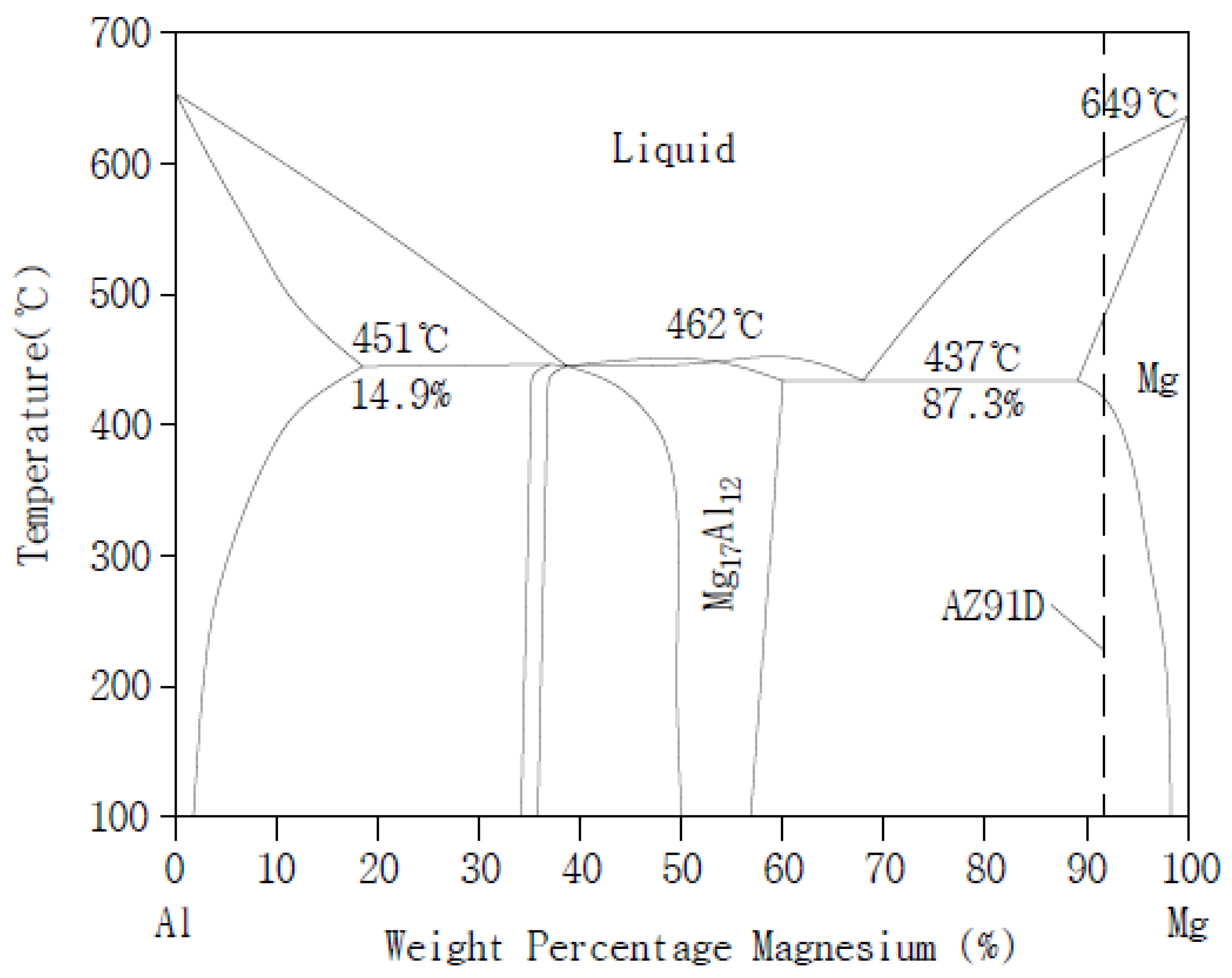
Magnesium is the lightest material among the practically used metals and has excellent specific strength and castability. Because pure magnesium has low room-temperature strength and corrosion resistance, its practical application is limited. To overcome this, various alloys added with Al, Zn, Mn, etc. have been developed. The AZ91D alloy adopted in this study is a representative magnesium alloy for die casting containing 9% Al, 1% Zn, and 0.15% Mn, as shown in Table 2. Al increases strength and heat resistance by forming an intermetallic compound with Mg, and Zn contributes to strength improvement through solid solution strengthening. Mn forms a compound with Fe and plays a role in improving corrosion resistance. AZ91D alloy is easy to form into thin sections due to its excellent castability, and it has mechanical properties of 230 MPa in tensile strength and 3% elongation. In addition, the microstructure consists of an α-Mg matrix and a β-Mg17Al12 intermetallic compound, and the formation mechanism and distribution of these phases during the solidification process have a great influence on the final physical properties. The microstructure development process under equilibrium and non-equilibrium solidification conditions can be explained by referring to the phase diagram according to Al content.

2.3. Process Design Conditions for Sheet Metal Forming

To ensure the formability of thin plates in the die casting process, mold design and process optimization that can comprehensively control the flow, solidification behavior, and shrinkage defects of the molten metal are necessary. Through this, excellent quality can be maintained by uniform filling of the molten metal and control of solidification shrinkage. The most important design factors include the gate, overflow, air vent, and cooling channel.

2.3.1. Gate System Design

The gate is a passage through which molten metal flows into the mold, and it has a direct impact on product quality and productivity. Because securing the fluidity of the molten metal in a thin cavity is key in the case of thin plate products, a high gate speed (40 to 60 m/s) is required. The gate speed in the charging stage can be expressed as Equation (7), where Ap is plunger tip cross-sectional area, Ag is the gate area, vi is the injection speed, and vg is the gate speed.
υ g = υ i A p A g
Here, the velocity times area is equal to the volumetric flow rate. When Wg is the cavity filling weight, t is the charging time, and ρ is the molten metal density, the charging time is Equation (8).
t = ρ Q g = W g V · υ g · A g
If the gate speed is too high, mold erosion or oxide mixing may occur. The charging time must be set within an appropriate range.

2.3.2. Overflow and Air Vent Design

Overflow and air vent are very important elements in die casting mold design that play a role in minimizing casting defects through uniform filling of molten metal and discharge of air bubbles and oxides. In particular, optimal overflow and air vent design are essential when casting thin plates of materials with low fluidity and fast solidification speed, such as magnesium alloy. The overflow accommodates excess molten metal after cavity filling is completed and prevents defects due to solidification shrinkage. In the case of thin plate products, the overflow capacity relative to the product volume is around 20%. If the capacity is excessive, the coagulation time may be prolonged, and productivity may be reduced. The overflow capacity should be designed with the minimum capacity necessary to compensate for shrinkage. The thickness of the overflow should be 1.2 to 1.5 times the thickness of the product, but it is desirable to secure a minimum of 3 mm. The location of the overflow is determined at the final filling part to facilitate the flow of molten metal and promote the discharge of air bubbles. In the case of complex shapes, multiple overflows are distributed to prevent local stagnation of molten metal. At this time, it must be designed so that the molten metal arrives at the same time, considering the balance between each overflow. The direction of overflow should be perpendicular to the cavity, and, if necessary, tilted to facilitate discharge.
Air vents are used to suppress bubble defects by quickly discharging air and gases within the mold. During high-speed charging, high air pressure inside the cavity can interfere with the flow of molten metal. To effectively discharge air trapped in the cavity, the spacing, depth, and width of the air vent must be optimized. The spacing of air vents is usually less than 20 times the thickness of the product, but they are placed more densely in the final charging area. The depth should be at least 1/2 of the product thickness, and the width should be a uniform value of around 0.1 mm. The shape of the air vent is perpendicular to the filling direction and is tapered to prevent backflow of molten metal. In general, the taper angle is known to be in the range of 15 to 20°. A backflow prevention pin can be installed at the air vent entrance. Recently, there have been cases of improving exhaust efficiency by applying vacuum suction-type air vents. Because additional facility investment and process control are required in this study, cost-effectiveness must be carefully reviewed. For effective air vent design, preliminary flow analysis is essential. Through 3D charging simulation, the optimal solution can be efficiently derived by predicting the air pressure distribution according to the location and spacing of the air vent.

2.3.3. Cooling System Design

The cooling system is a key factor in controlling dimensional accuracy and mechanical properties by controlling shrinkage and residual stress during solidification. In the case of magnesium alloy thin plates, rapid cooling occurs due to their thin thickness. Therefore, uniform cooling control is of the utmost importance to prevent the occurrence of defects. To achieve this, optimal design of the cooling channel considering the shape and thickness distribution of the product must be preceded.
For thin plate products, it is recommended to place cooling pipes with a diameter of approximately 8 mm at 30 mm intervals. Considering heat transfer with the coolant, the distance from the product should be around 20 to 25 mm, but it should be placed somewhat further away from areas where shrinkage defects due to local overcooling are concerned. If necessary, channels may be divided, or shutoff valves may be installed so that the cooling rate can be partially adjusted.
The temperature of the coolant is determined in the range of 20 to 30 °C, considering the difference from the preheating temperature of the mold. If the temperature is too low, caution is required, as deformation and stress may occur due to rapid cooling. Excessively high temperatures can reduce the cooling efficiency and increase the cycle time. The flow rate is generally 10 to 20 L/min depending on the channel diameter and product thickness. However, this is only a theoretical calculated value, and deviations are bound to occur in actual operating conditions. Feedback control through temperature monitoring is necessary.
Meanwhile, the design of the cooling channel can be theoretically calculated based on the heat capacity and shape of each product, mold material, etc. Cooling load (Q), heat transfer coefficient (h), cooling area (A), and mold–coolant temperature difference (ΔT) can be expressed as Equation (9).
Q = h · A · Δ T .
The channel diameter and length that can satisfy this are calculated. However, not only is this a very cumbersome task, but errors also occur depending on assumptions. In recent years, design through filling and solidification analysis has become common, and through 3D heat flow analysis, the temperature distribution within the product can be predicted and the occurrence of local hot spots and cold spots can be identified in advance. Based on this, a plan must be devised to adjust the location and density of the cooling channel and apply auxiliary cooling means to the heat concentration area. In addition, to ensure cooling uniformity in multiple cavities with different shapes and thicknesses, there is a trend of considering balancing from the channel design stage.
The goal of cooling system design is to minimize residual stress and ensure dimensional stability through a uniform cooling rate. However, this is by no means an easy task, and it can only be achieved by complexly considering the effects of various factors such as material properties, product shape, and process conditions. The attitude of pursuing optimization through systematic analysis, data-based design, and continuous process monitoring and feedback is most important. This is an area that should be recognized and strengthened as a core technological competency, as it not only reduces defects, but also directly leads to cost reduction and quality competitiveness.

2.3.4. Casting Analysis Simulation

Because complex physical phenomena occur in a very short time in the die casting process, it is not easy to find optimal conditions through experimental approaches alone. Recently, the development of CAE technology has made it possible to simulate the die casting process, which can optimize process conditions and predict defects. Magma, Procast, and Anycasting are widely used as commercial casting analysis programs. These programs can link the charging and solidification processes of molten metal based on the finite element method (FEM) or finite difference method (FDM). It is possible to predict molten metal behavior according to key design variables such as gate, overflow, and air vent, and to visualize defect occurrence patterns.
Based on the theoretical background, we are implementing analysis simulation technology and can optimize cooling conditions to minimize temperature changes within the product by quantifying solidification time, temperature distribution, and shrinkage patterns. In addition, residual stress and distortion can be evaluated in advance, greatly reducing the time and cost required for mold modification. In addition, it is expected that casting defects can be fundamentally suppressed by identifying locations where temperature drop, or segregation occurs at the tip of the molten metal and reflecting this in the mold design.
Because the simulation results are only approximate solutions under assumed boundary conditions, comparison and verification with actual castings is essential. For highly accurate analysis, the construction of a basic database on the physical properties of molten metal and mold materials, heat transfer conditions, and interface phenomena must be established in advance. In addition, the analysis model must be advanced through continuous feedback with experimental results that reflect the field conditions.
In this way, casting simulation technology can greatly contribute to overcoming existing empirical methods and accelerating process optimization. Its effectiveness is expected to be doubled in processes that require a high level of flow control, such as thin plate die casting. This can be a shortcut to stably produce high-quality products by establishing a design foundation through analysis and minimizing trial and error. However, interpretation itself should not be the goal, but should be thoroughly recognized and utilized as a tool forthe ultimate value of cost reduction and quality improvement.

3. Experiment Method

3.1. Optimizing Design Conditions through Simulation

In this study, we attempted to form 0.5 mm thin plate products using AZ91D material, one of the magnesium alloys for die casting. To minimize trial and error and derive the optimal mold design, analysis simulation was used, which enabled us to analyze filling and solidification behavior for various design variables and predict the possibility of casting defects. For the casting analysis simulation, Anycasting v6.9, a commercial program from Anycasting Software, was used to conduct the analysis.

3.1.1. Experimental Conditions and Variables

The magnesium alloy used in the simulation was AZ91D, and the phase diagram of the metal is shown in Figure 2. The liquidus and solidus temperatures were set at 595 °C and 470 °C, respectively.
The main experimental variables were molten metal injection temperature, mold temperature, and cooling water inlet and outlet temperatures, which are conditions that can be easily controlled on-site during actual product manufacturing. The experimental conditions were shown in Table 3. In addition, the charging behavior of the molten metal was additionally observed by applying side and tunnel gates, respectively.
The conditions of injection temperature has the following meaning. CASE 1 is a casting condition for die casting that generally uses magnesium alloy and was intended to be used as a standard by referring to the behavior shown in the simulation. CASE 2 and CASE 3 were set up to observe the difference in filling behavior at high and low temperatures, assuming changes in mold temperature according to changes in injection temperature. CASE 4 and CASE 5 changed the injection temperature but maintained the mold temperature by controlling the temperature of the coolant and were determined to compare the behavior according to the change in mold temperature due to the coolant.
In the gate method, a side gate was applied because it was impossible to change the structure by combining the cast product with its counterpart. Although there are limits to the area that can be selected depending on the shape of the casting, this experiment attempted to observe the charging behavior when the molten metal was charged at high speed by applying a tunnel gate to some sections.

3.1.2. Charging Behavior and Defect Prediction

Simulation was performed according to the above conditions, and the filling pattern of the molten metal and the location of occurrence of bubbles and shrinkage defects for each case were predicted. The physical properties of the AZ91D alloy used in the analysis were applied to the analysis using conditions considering changes in physical properties according to temperature, such as latent heat, density, and thermal conductivity, as shown in Table 4.
The analysis model was constructed to include the product, runner, and overflow areas. The element network was divided into a total of 12.9 million elements by applying a hexahedral grid system. As a boundary condition, a temperature-dependent function was applied to the heat transfer coefficient between the mold and molten metal, and default settings were applied to radiation and convection heat transfer with the atmosphere.
We focused on predicting poor filling and pore defects, which can be vulnerable to thin plate shapes. For this purpose, the molten metal behavior was intensively analyzed in key areas such as areas around the gate and overflow, the corners of the product, and areas with fast cooling rates. Charging defects that may occur in the final charging stage and defects due to gas in the cavity were predicted. In addition, we attempted to optimize the process conditions required for sheet metal forming by comparing solidification patterns, mold erosion, and oxide generation.

3.2. Prototype Production under Optimal Conditions

To facilitate the flow of molten metal, a gap was provided at the mold joint area such as the hole shape inside the product to minimize metal boundary defects. Burrs, overflows, gates, etc., were removed by trimming after casting production.

3.2.1. Materials and Equipment

An actual thin plate prototype was produced under optimal conditions selected based on the simulation results. The used material was AZ91D magnesium alloy ingot, and it was cast under the conditions of CASE 1. The die casting process used a cold-chamber-type 125-ton die casting machine, and a side gate was used as the gate. The gate into which the molten metal was injected is shown at location 1 in Figure 3.

3.2.2. Process Conditions

In the actual molding process, the temperature of the molten metal, mold temperature, cooling temperature, and flow rate were determined to be the same as the conditions of CASE 1 of the simulation. The melting furnace temperature was 680 °C to achieve an injection temperature of 640 °C. The casting speeds were 35 cm/s at low speed and 380 cm/s at high speed, and the low-speed section was set at 80 mm and the high-speed start section at 100 mm for a total sleeve length of 205 mm. The mold temperature controller value was fixed to 300 °C to maintain the mold temperature at 190 °C, and spraying was performed in stages of air 1 (0.3 s), release agent (0.2 s), air 2 (0.5 s), and air 3 (0.3 s). Under these conditions, multiple prototypes were manufactured, and various characteristics were evaluated. The tensile properties of 0.5 mm- thick specimens were evaluated using a universal material testing machine (SHIMADZU, Kyoto, Japan). A total of 6 specimens were manufactured, with 2 each at the left, right, and center positions centered on the thin part with a thickness of 0.5 mm. Measurements were taken twice at each location, and the average value was derived.

3.3. Evaluation of Prototype Properties

To evaluate the characteristics of the manufactured prototype, mechanical properties and microstructure were observed. By comparing the results analyzed through simulation, it was assessed whether there were actual defects within the expected range.

3.3.1. Microstructure Observation

The microstructure of the prototype was observed using an optical microscope Nikon TS100 (Nikon, Tokyo, Japan). For the observation location, the product was divided into certain sections as shown in Figure 4, and tissue photos were then taken for each area and the grain size and distribution of precipitates were compared and analyzed.

3.3.2. Mechanical Property Measurement

Figure 4 shows the 0.5 mm-thick, thin plate part indicated in the drawing of the prototype. It was 107.66 mm in width and 47.13 mm in height. The prototype for which microstructure observation was completed, was used to measure the tensile strength and hardness. The tensile properties of 0.5 mm-thick specimens were evaluated using a universal testing machine and were performed under constant strain rate conditions at room temperature. The specimens were manufactured by sampling at the left (5, 8, 11), center (6, 9, 12), and right (7, 10, 13) locations centered on the thin-walled portion. Repeated measurements were taken at each location to derive the average value.

4. Results and Discussion

4.1. Simulation Analysis Results

To derive the optimal conditions for 0.5 mm thin plate products of AZ91D magnesium alloy, analytical simulation was used to analyze the filling and solidification behavior of molten metal according to casting conditions and to predict the occurrence of casting defects.

4.1.1. Changes in Charging Behavior Depending on Design Conditions

The charging behavior was analyzed by applying the casting temperature change previously determined in experimental conditions and variables to each condition. As shown in the simulation results of the CASE 1 (Figure 5a) condition, the color indicates the charging time. The charging behavior spread rapidly from the center and bottom of the product, and a fast-filling rate was observed from the gate to the thin section. In addition, from the section after the thin-walled part, overall charging was uniform on the left and right sides. The rib portion in the front direction was shown to be charged late. This phenomenon appeared to be due to rapid charging of the molten metal and the molten metal on the bottom being charged first. After charging the thin part, the ribs, overflow, and chill vent were sequentially charged with molten metal. This shows the ideal charging state. The simulation results of CASE 2 (Figure 5b) shows similar charging to CASE 1 and because the conditions included a higher temperature than that in CASE 1, the charging time of the molten metal was reduced by about 1.8%. The simulation results of CASE 3 (Figure 5c) show that the charging behavior is like CASE 1, but the charging time increases by about 6.6% due to low-temperature molten metal charging compared to CASE 1. Additionally, the simulation results for CASE 4 (Figure 5d) show the same results as CASE 2. Likewise, it was confirmed that the simulation results of CASE 5 (Figure 5e) show the same results as CASE 3. As a result, based on an injection temperature of 640 °C and a mold temperature of 190 °C, under the conditions of 670 °C/220 °C in CASE 2, the overall charging speed increased due to increased molten metal fluidity and the charging time was shortened by about 1.8%. Under CASE 3 conditions of 610 °C/160 °C, the charging time tends to increase by about 6.6% along with a decrease in speed. This is believed due to changes in the viscosity of the alloy depending on the temperature. Meanwhile, in CASEs 4 and 5, where the coolant temperature was in the range of 10~40 °C and 40~55 °C, there was no significant change in charging speed. Through this, the initial temperature of the molten metal and mold had a dominant influence on the sheet filling behavior, and the contribution of the cooling rate was relatively small. Under low-temperature conditions below 610 °C, the risk of shrinkage defects would increase due to increased flow stagnation.
Figure 6 shows the results of a simulation by transforming the behavior of molten metal into particles to predict the turbulence phenomenon or flow of molten metal. When the side gate was applied, the molten metal showed normal charging behavior, while the tunnel gate showed that the molten metal was charged along the ribs in the front direction.
It was confirmed that the injection method and molten metal and mold temperature are important factors for molten metal filling in the die casting process.

4.1.2. Predicting Defect Occurrence Pattern

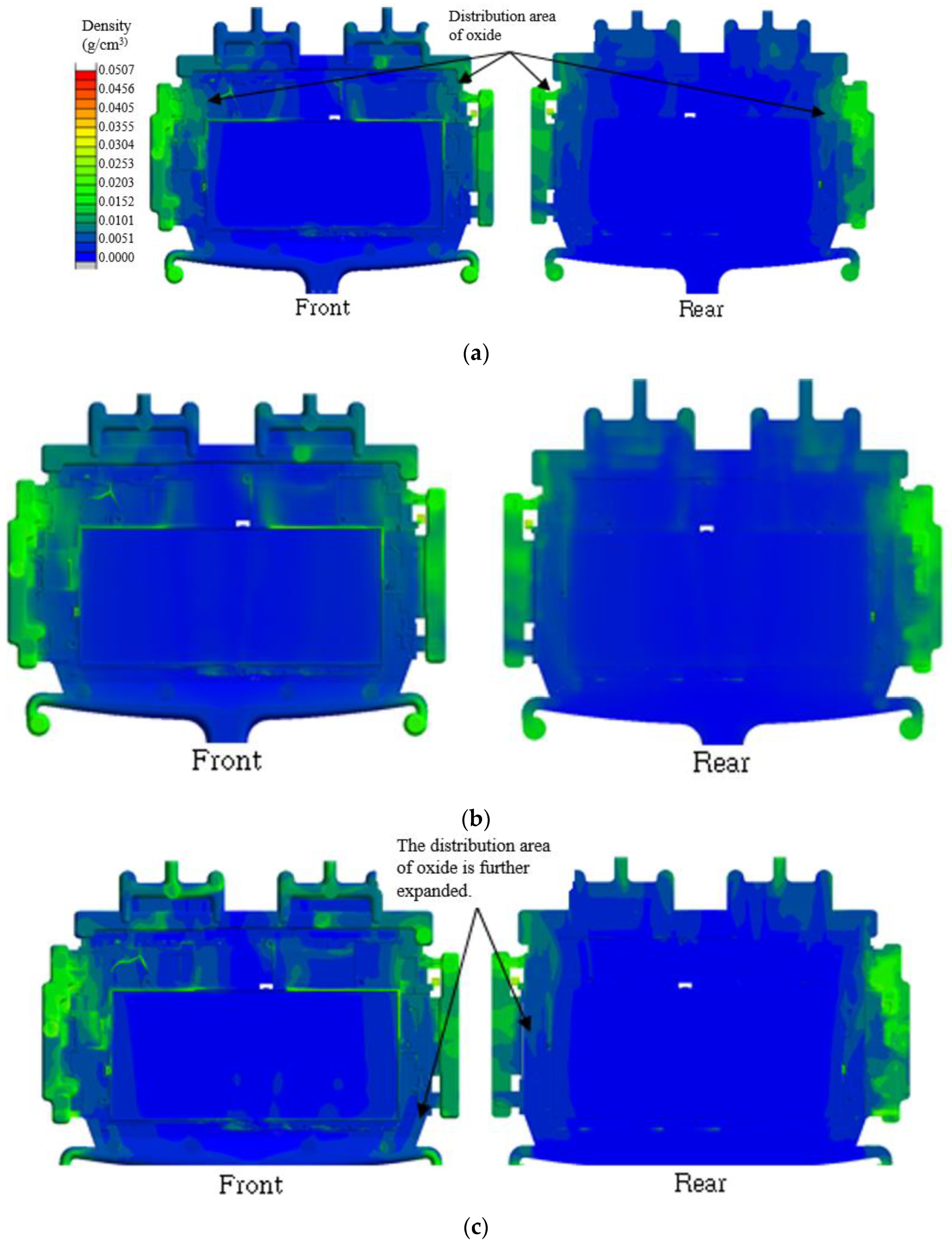
As a result of the simulation, the oxide distribution was as shown in Figure 7. It was generally concentrated in the overflow and chill vents, and it appears that oxides may have also been present in the ribs. As a result, it was confirmed that oxides were generated in the area where charging ended. More oxides were identified in CASE 3 (Figure 7c) and CASE 5 (Figure 7e). Due to the slowing of charging behavior due to the low injection temperature, the contact time between molten metal and air was prolonged, which is believed to have had a more dominant effect on oxide formation.
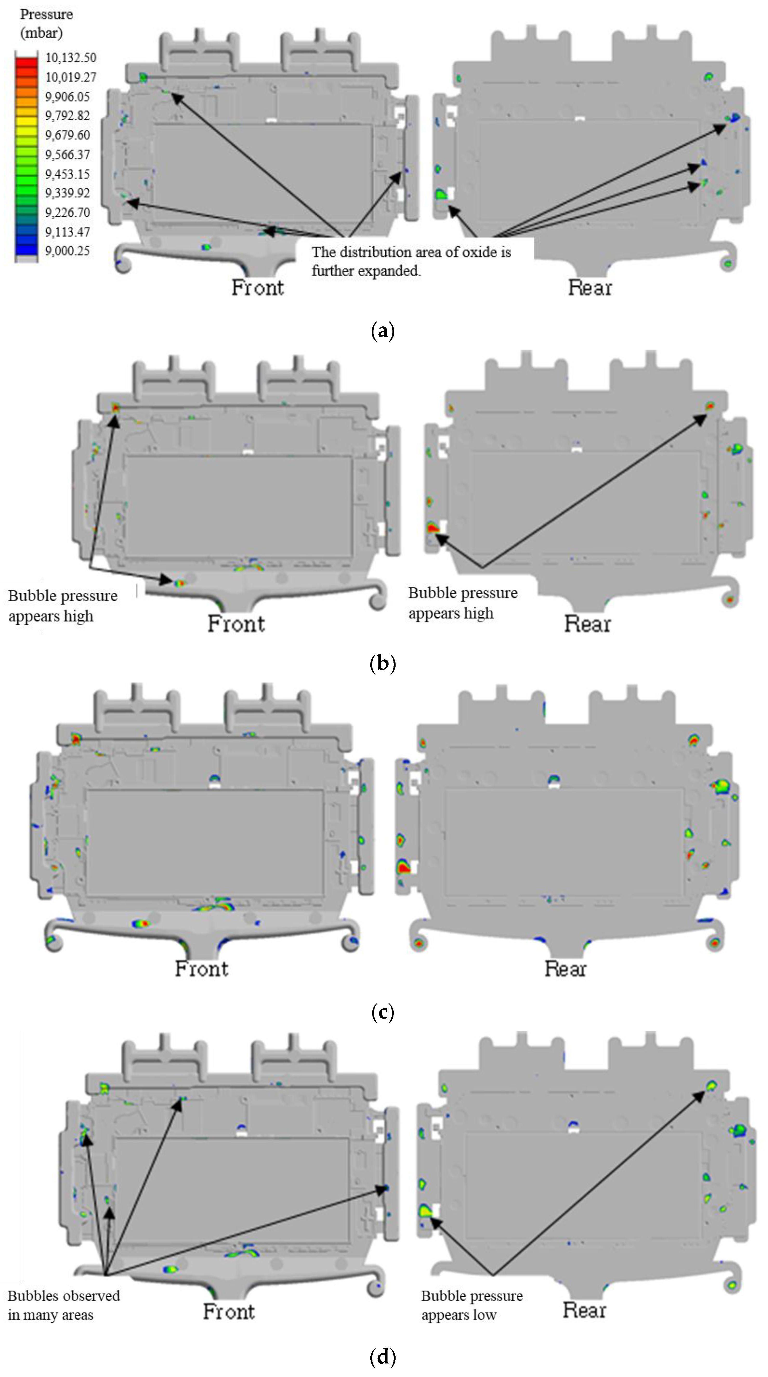
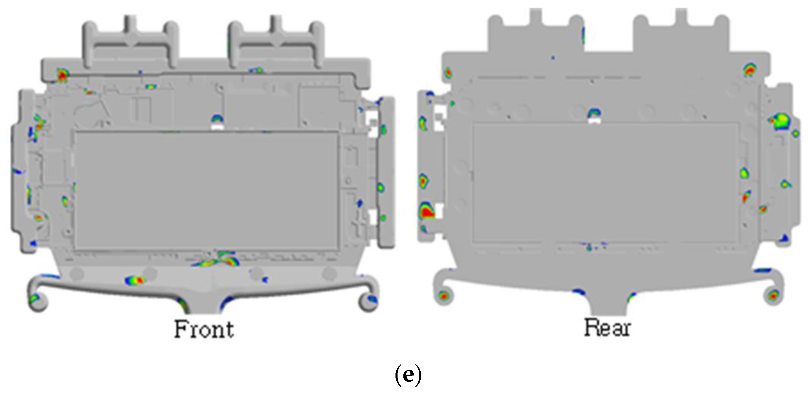
As a result of the simulation, the distribution of bubbles was generally expected in the overflow, runner, and gate, and the distribution and pressure of bubbles were found to be the lowest in CASE 1 (Figure 8a) casting conditions. In addition, the number of pores generated was high in the relatively low-temperature casting conditions of CASE 3 (Figure 8c) and CASE 5 (Figure 8e). This is believed to have been due to incomplete filling due to reduced fluidity and the resulting shrinkage defects. Porosity was evident near the edges of the product, and a local solidification delay was presumed to be the main cause.
Compared with CASE 1, the distribution of bubbles in CASE 2 (Figure 8b) casting conditions was similar in distribution and size, but the pressure of the bubbles was high. It appeared that the pressure increased as the mold temperature increased. In the casting conditions of CASE 4 (Figure 8d), the pressure of bubbles was lower than that of CASE 1, but the distribution of bubbles was found to be large. This phenomenon is believed to be caused by shrinkage defects as the mold temperature decreased.
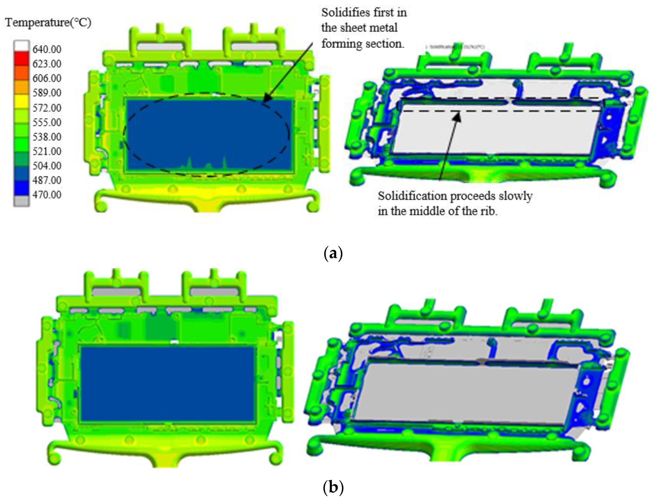
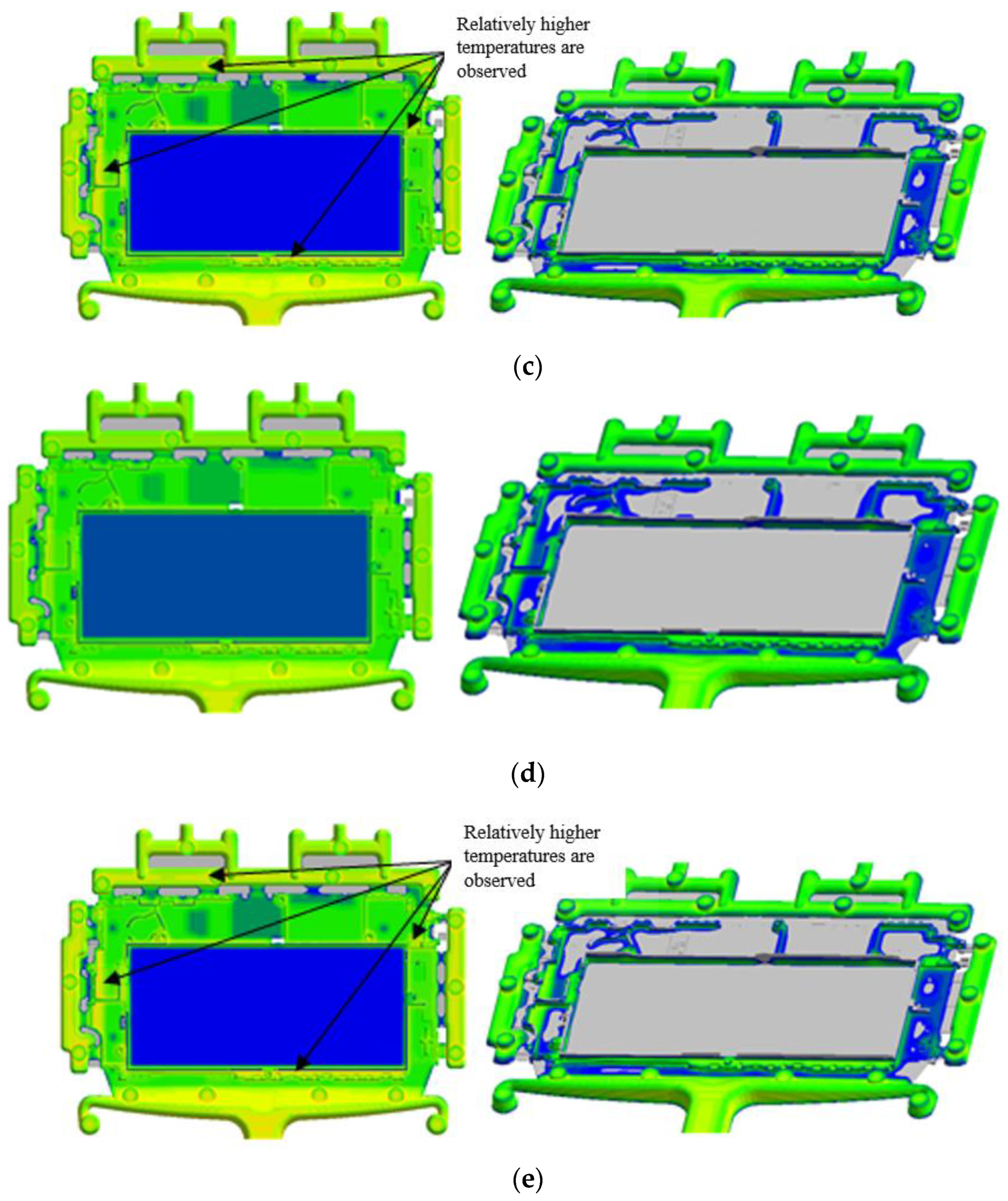
The simulation results of CASE 1 (Figure 9a) casting conditions showed a change in temperature due to solidification after the filling of the product was completed. Coagulation occurred first in the thin-walled area. Overflow, runner, etc., were the last to solidify. In the product department, solidification of the middle part of the rib progressed last. These results are believed to be caused by the fact that casting filling rate was slowest for the ribs and the temperature at the top of the ribs was relatively low, resulting in different solidification rates. Also, unlike other conditions, the casting conditions of CASE 3 (Figure 9c) and CASE 5 (Figure 9e) showed a faster solidification rate. These results are believed to be due to a decrease in mold temperature during the solidification process caused by the relatively low injection temperature. As a result of the simulation, it was confirmed that the mold temperature of CASE 1 was 228 °C and that of CASE 5 was 222 °C.

4.2. Characteristics of the Prototype

4.2.1. Influence of Microstructure

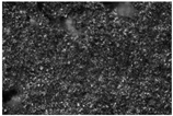
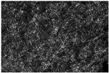
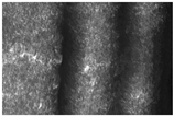
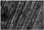
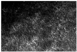
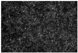
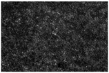
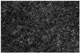
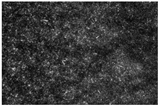
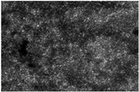
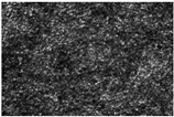
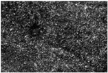
The microstructure of a 0.5 mm thin plate prototype produced under the casting conditions of CASE 1 was photographed using an optical microscope. Table 5 shows the optical micrographs of the numbered portions in Figure 3. A generally uniform microstructure was observed. The primary α -Mg crystal grains became finer because of rapid cooling. The β -Mg17Al12 precipitate phase was distributed in a network at the grain boundaries, and some intermetallic compounds were also observed due to the addition of alloy elements.
The grains of runner No. 1 in Table 5 were clearly different from those of other parts. Considering that the crystal grains were large and dispersed, the thickness of this area was the thickest at 7 mm. It is expected that this phenomenon occurred as cooling slowed down. The microstructures of ingate Nos. 2, 3, and 4 had very fine crystal grain structures, and crystal growth was suppressed due to the rapid cooling rate, allowing a fine and uniform crystal structure to be observed. However, oxides or impurities that appeared dimly and brightly were also observed. At the beginning of the thin plate molding section, fine equiaxed crystal grain structures such as Nos. 5, 6, and 7 were observed, which is believed to have been due to rapid precipitation caused by the cooling rate. The microstructures of Nos. 8, 9, and 10, which were the midpoints of the sheet-metal-forming section, were the same as Nos. 5 to 7, but the unevenness increased in some areas. In No. 9, fine shrinkage or gas cavities were observed, which was believed to be a casting defect, but a uniform crystal structure was distinguished in most areas. Segregation and pores in dark areas were found in the microstructure of Nos. 11, 12, and 13 at the ends of the thin plate molding sections. This was expected to be a casting defect, but the crystal grains were fine, which is believed to have been due to the fast-cooling rate. A uniform equiaxed crystal structure was observed in the microstructure of the end part No. 14 of the product, and stable cooling conditions were observed. However, similarly to No. 12 and the microstructure, casting defects due to segregation pores were observed. In the left and right out-gate microstructures Nos. 15 and 16, the grain size increased due to slow cooling, and precipitates due to increased segregation began to form more clearly along the grain boundaries. Out gates Nos. 17 and 18 at the end showed diversity in the size and distribution of precipitates due to the rapid flow of molten metal and non-uniformity of cooling conditions.
Almost no pores or shrinkage holes were found in the product, and a generally fine and uniform crystal structure was observed. This is believed to be the effect of uniform cooling and is interpreted as a result supported by the appropriate design of the spout, overflow, and air vent. The fraction of oxide inclusions was also at a very low level, and it was evaluated that the molten metal was effectively protected and purified. However, uneven distribution of precipitates was observed in some areas, which is expected to be due to variation in the cooling rate. The fine equiaxed crystal grain structure observed earlier was due to an increase in the nucleation rate and inhibition of crystal growth due to rapid cooling. By applying the model of the enthalpy method, it can be confirmed that the grain size predicted from the cooling rate under this experimental condition matched well with the actual observation results.

4.2.2. Influence of Mechanical Properties

The tensile properties of the 0.5 mm prototype manufactured under the casting conditions of CASE 1 showed an average tensile strength of 190~220 MPa from room-temperature testing, and excellent physical properties of at least 15% compared to existing bulk materials were observed. This is believed to be due to the grain refinement effect caused by rapid cooling. However, differences in physical properties were observed depending on the prototype with casting defects. The strength of the center appeared to be somewhat lower than that of the surface, which is presumed to be the effect of local segregation or residual stress. Therefore, controlling the homogeneous microstructure is more important than anything else to ensure the reliability of thin plate products.
Meanwhile, hardness was measured using Mitutoyo’s HM-100 model (Mitutoyo, Kanagawa, Japan), and relatively uniform values of an average of 54 to 58 Hv were obtained. However, the hardness itself was evaluated as not being very high. This was due to the unique characteristics of AZ91D, and it is believed that research on more precise heat treatment conditions is necessary to improve the strength and hardness.

5. Conclusions

In this study, a die casting process optimization method for manufacturing thin plate products of magnesium alloy AZ91D of 0.5 mm or less was presented. The effects of casting temperature and mold design variables on the quality of sheet metal were systematically analyzed through pre-filling and solidification analysis using a commercial analysis program. An actual prototype was manufactured by applying the derived optimal conditions, and an evaluation of the microstructure and mechanical properties was performed.
As a result of the simulation analysis results and mechanical properties, it was found that the occurrence of defects related to porosity and shrinkage was minimized along with uniform filling behavior under the conditions of molten metal injection temperatures of 640~670 °C and mold temperatures of 190~220 °C. In addition, the uniformity of the molten metal filling flow within the thin plate was improved through optimal design of the runner, gate, and overflow. It was confirmed that residual stress and deformation due to cooling rate deviation could be minimized by optimizing the cooling channel arrangement. Meanwhile, the 0.5 mm AZ91D alloy prototype manufactured under the above conditions showed a fine and homogeneous grain structure. This is believed to be due to the rapid cooling effect caused by high-speed charging. In addition, by securing the tensile strength of 190~220 MPa, it was possible to implement excellent properties that were 15% higher than the existing bulk material. The hardness also showed a uniform value of 54~58 Hv throughout the specimen, suggesting that quality stability can be improved through improved tissue homogeneity.
The above results are significant in that they succeeded in producing 0.5 mm ultra-thin plate products from magnesium alloys, which were previously considered difficult problems. The optimized process conditions were applied through computer simulation, and actual products were manufactured and verified based on this. The material’s unique properties were implemented, and the occurrence of casting defects was suppressed.
However, for commercial product application, it is believed that long-term reliability evaluation and improvement of mechanical properties through alloy design are necessary. To expand demand in the transportation equipment field, which requires high strength and corrosion resistance, it is essential to utilize advanced elements and combine surface treatment technology. In addition, the development of bonding and coating technologies that take material compatibility into account should be developed in parallel.
Meanwhile, the thin plate casting process optimization system established in this study is expected to be applicable to other lightweight alloys and complex shape products other than magnesium. This is because mold design optimization and experimental verification processes based on filling and solidification simulation can greatly contribute to cost reduction and shortening the development period.

Author Contributions

Conceptualization, J.-T.H. and S.-J.M.; methodology, J.-T.H. and C.-M.R.; software, J.-T.H.; validation, J.-T.H. and C.-M.R.; formal analysis, J.-T.H. and C.-M.R.; investigation, J.-T.H. and C.-M.R.; resources, S.-J.M.; data curation, J.-T.H. and C.-M.R.; writing—original draft preparation, J.-T.H. and C.-M.R.; writing—review and editing, S.-J.M.; visualization, C.-M.R.; supervision, S.-J.M.; project administration, S.-J.M.; funding acquisition, S.-J.M. All authors have read and agreed to the published version of the manuscript.

Funding

This work was supported by the Korea Institute for Advancement of Technology (KIAT), titled “Development of a highly versatile quartz transmittance analysis system based on multi-wavelength laser to improve the semiconductor RTP process” (No. RS-2024-00434898).

Data Availability Statement

The original contributions presented in the study are included in the article, further inquiries can be directed to the corresponding author.

Conflicts of Interest

The authors declare no conflicts of interest.

References

  1. Polmear, I.J. Magnesium alloys and applications. Mater. Sci. Technol. 1994, 10, 1–16. [Google Scholar] [CrossRef]
  2. Yang, Y.; Xiong, X.; Chen, J.; Peng, X.; Chen, D.; Pan, F. Research Advances in Magnesium and Magnesium Alloys Worldwide in 2020. J. Magnes. Alloys 2021, 9, 705–747. [Google Scholar] [CrossRef]
  3. Xu, T.; Yang, Y.; Peng, X.; Song, J.; Pan, F. Overview of Advancement and Development Trend on Magnesium Alloy. J. Magnes. Alloys 2019, 7, 536–544. [Google Scholar] [CrossRef]
  4. Song, J.; She, J.; Chen, D.; Pan, F. Latest Research Advances on Magnesium and Magnesium Alloys Worldwide. J. Magnes. Alloys 2020, 8, 1–41. [Google Scholar] [CrossRef]
  5. Ali, Y.; Qiu, D.; Jiang, B.; Pan, F.; Zhang, M.X. Current Research Progress in Grain Refinement of Cast Magnesium Alloys: A Review Article. J. Alloys Compd. 2015, 619, 639–651. [Google Scholar] [CrossRef]
  6. Luo, A.A. Magnesium Casting Technology for Structural Applications. J. Magnes. Alloys 2013, 1, 2–22. [Google Scholar] [CrossRef]
  7. You, B.S.; Yim, C.D.; Kim, S.H. Solidification of AZ31 Magnesium Alloy Plate in a Horizontal Continuous Casting Process. Mater. Sci. Eng. A 2005, 413–414, 139–143. [Google Scholar] [CrossRef]
  8. Hu, L.; Chen, S.; Miao, Y.; Meng, Q. Die-Casting Effect on Surface Characteristics of Thin-Walled AZ91D Magnesium Components. Appl. Surf. Sci. 2012, 261, 851–856. [Google Scholar] [CrossRef]
  9. Barone, M.R.; Caulk, D.A. Analysis of Liquid Metal flow in Die Casting. Int. J. Eng. Sci. 2000, 38, 1279–1302. [Google Scholar] [CrossRef]
  10. Qin, X.-Y.; Su, Y.; Chen, J.; Liu, L.-J. Finite Element Analysis for Die Casting Parameters in High-Pressure Die Casting Process. China Foundry 2019, 16, 272–276. [Google Scholar] [CrossRef]
  11. Syrcos, G.P. Die Casting Process Optimization Using Taguchi Methods. J. Mater. Process. Technol. 2003, 135, 68–74. [Google Scholar] [CrossRef]
  12. Iwata, Y.; Dong, S.; Sugiyama, Y.; Iwahori, H. Change in Molten Metal Pressure and Its Effect on Defects of Aluminum Alloy Die Castings. Mater. Trans. 2014, 55, 311–317. [Google Scholar] [CrossRef]
  13. Ibrahim, M.D.; Rahman, M.R.A.; Khan, A.A.; Mohamad, M.R.; Suffian, M.S.Z.M.; Yunos, Y.S.; Wong, L.K.; Mohtar, M.Z. Effect of Mold Designs on Molten Metal Behaviour in High-Pressure Die Casting. J. Phys. Conf. Ser. 2017, 822, 12029. [Google Scholar] [CrossRef]
  14. Dumanić, I.; Jozić, S.; Bajić, D.; Krolo, J. Optimization of Semi-Solid High-Pressure Die Casting Process by Computer Simulation, Taguchi Method and Grey Relational Analysis. Int. J. Met. 2021, 15, 108–118. [Google Scholar] [CrossRef]
  15. Fu, J.; Wang, K. Modelling and Simulation of Die Casting Process for A356 Semisolid Alloy. In Proceedings of the Procedia Engineering; Elsevier Ltd.: Amsterdam, The Netherlands, 2014; Volume 81, pp. 1565–1570. [Google Scholar]
  16. Li, Y.; Wei, Z. Numerical Simulation of Filling Process in Die Casting. Mater. Technol. 2003, 18, 36–41. [Google Scholar]
  17. Chen, Z.; Li, Y.; Zhao, F.; Li, S.; Zhang, J. Progress in Numerical Simulation of Casting Process. Meas. Control 2022, 55, 257–264. [Google Scholar] [CrossRef]
  18. Dou, K.; Lordan, E.; Zhang, Y.J.; Jacot, A.; Fan, Z.Y. A Complete Computer Aided Engineering (CAE) Modelling and Optimization of High Pressure Die Casting (HPDC) Process. J. Manuf. Process. 2020, 60, 435–446. [Google Scholar] [CrossRef]
  19. Ma, C.; Yu, W.; Zhang, T.; Zhang, Z.; Ma, Y.; Xiong, S. The Effect of Slow Shot Speed and Casting Pressure on the 3D Microstructure of High Pressure Die Casting AE44 Magnesium Alloy. J. Magnes. Alloys 2023, 11, 753–761. [Google Scholar] [CrossRef]
  20. Chang, X.Y.; Shen, Q.; Fan, W.X.; Hao, H. Optimization of Magnesium Alloy Casting Process: An Integrated Computational Materials Engineering (ICME) Approach. Mater. Sci. Forum 2021, 1035, 808–812. [Google Scholar] [CrossRef]
  21. Li, J.; Chen, L.; Jiang, S.; Gan, H.; Hao, W. Numerical Simulation and Process Optimization of Magnesium Alloy Vehicle Dashboard Cross Car Beam (CCB) Based on MAGMA. Processes 2023, 11, 16. [Google Scholar] [CrossRef]
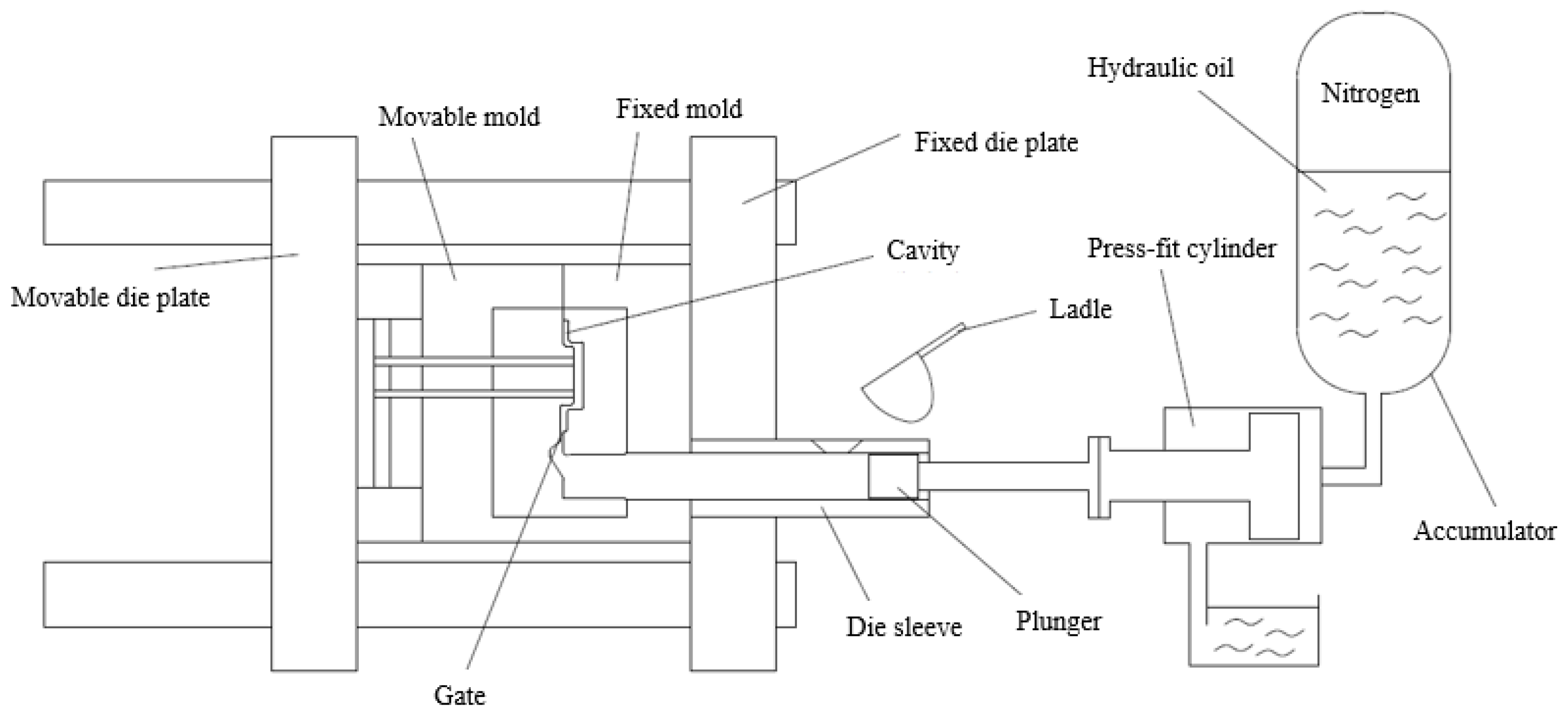
Figure 1. Cold chamber die casting machine.
Metals 14 00970 g001
Figure 2. Mg-Al phase diagram.
Metals 14 00970 g002
Figure 3. Microstructure observation positions (1–18) of the prototype.
Metals 14 00970 g003
Figure 4. The location and dimensions of the 0.5 mm-thick, thin plate of the prototype.
Metals 14 00970 g004
Figure 5. Charging speed distribution according to casting conditions. (a) CASE 1, (b) CASE 2, (c) CASE 3, (d) CASE 4, (e) CASE 5.
Metals 14 00970 g005aMetals 14 00970 g005bMetals 14 00970 g005c
Figure 6. Charging behavior depending on gate type.
Metals 14 00970 g006
Figure 7. Oxide distribution during molten metal charging. (a) CASE 1, (b) CASE 2, (c) CASE 3, (d) CASE 4, (e) CASE 5.
Metals 14 00970 g007aMetals 14 00970 g007b
Figure 8. Prediction results of pore distribution according to casting conditions. (a) CASE 1, (b) CASE 2, (c) CASE 3, (d) CASE 4, (e) CASE 5.
Metals 14 00970 g008aMetals 14 00970 g008b
Figure 9. Solidification behavior results according to casting conditions. (a) CASE 1, (b) CASE 2, (c) CASE 3, (d) CASE 4, (e) CASE 5.
Metals 14 00970 g009aMetals 14 00970 g009b
Table 1. Comparison of properties of die casting alloys (Mg, Al, Zn).
ElementStrength (MPa)Density (kg/m3)Specific Strength (MPa m/kg)
Mg2501.81138
Al3152.72.7
Zn2216.633
Table 2. Types and chemical composition of alloys for die casting.
ElementAZ91DALDC12
Al8.3~9.7Bal.
Zn0.35~1.01.0 or less
Mn0.15 or higher0.5 or less
Si0.1 of less9.6~12.0
Cu0.03 or less1.5~3.5
Ni0.002 or less0.5 or less
Fe0.005 or less0.9 or less
MgBal.0.3 or less
Sn-0.2 or less
Table 3. Casting experimental conditions.
SampleMolten Metal Injection Temperature (°C)Mold Temperature (°C)Coolant Temperature (°C)
InletOutlet
CASE 16401902540
CASE 26702202540
CASE 36101602540
CASE 46701901040
CASE 56101904055
Table 4. Physical properties of AZ91D alloy.
PropertyUnitTemp. Condition (°C)AZ91D Properties
Densityg/cm3201.81
Linear thermal experimental coefficientμm/m·K20–10026
Specific heat of fusion kJ/kg 370
Specific heat kJ / kg · K 201.02
Thermal conductivity W / K · m 2051
Electrical conductivityMS/m206.6
Table 5. Microstructure of a thin plate prototype taken with an optical microscope.
MicrostructureMetals 14 00970 i001Metals 14 00970 i002Metals 14 00970 i003
Measurement
location
2 (Ingate left)3 (Ingate center)4 (Ingate right)
MicrostructureMetals 14 00970 i004Metals 14 00970 i005Metals 14 00970 i006
Measurement
location
15 (Outgate left)1 (Runner center)16 (Outgate right)
MicrostructureMetals 14 00970 i007Metals 14 00970 i008Metals 14 00970 i009
Measurement
location
17 (Outgate left)14 (Product center)18 (Outgate right)
MicrostructureMetals 14 00970 i010Metals 14 00970 i011Metals 14 00970 i012
Measurement
location
5 (0.5 mm left)6 (0.5 mm center)7 (0.5 mm right)
MicrostructureMetals 14 00970 i013Metals 14 00970 i014Metals 14 00970 i015
Measurement
location
8 (0.5 mm left)9 (0.5 mm center)10 (0.5 mm right)
MicrostructureMetals 14 00970 i016Metals 14 00970 i017Metals 14 00970 i018
Measurement
location
11 (0.5 mm left)12 (0.5 mm center)13 (0.5 mm right)
Disclaimer/Publisher’s Note: The statements, opinions and data contained in all publications are solely those of the individual author(s) and contributor(s) and not of MDPI and/or the editor(s). MDPI and/or the editor(s) disclaim responsibility for any injury to people or property resulting from any ideas, methods, instructions or products referred to in the content.