Article

Effects of Composition on Melt Fillability and Impact Resistance of TiAl Alloys for Thin-Blade Turbine Wheels: Laboratory Predictions and Product Verification

1
National Institute for Material Science, Sengen 1-2-1, Tsukuba 305-0047, Ibaraki, Japan
2
FuSheng Precision Co., Ltd., No. 9, Xingzhong Street, Taoyuan District, Taoyuan City 33068, Taiwan
3
Safran Tech, Materials and Processes, Rue des Jeunes Bois, 78114 Châteaufort, France
*
Author to whom correspondence should be addressed.
Metals 2025, 15(5), 474; https://doi.org/10.3390/met15050474
Submission received: 19 March 2025 / Revised: 15 April 2025 / Accepted: 21 April 2025 / Published: 22 April 2025
(This article belongs to the Special Issue Properties, Microstructure and Forming of Intermetallics)

Abstract

:
Scaling up the production of TiAl turbine wheels for passenger car turbochargers requires the fabrication of thin blades that are similar to those of nickel-based superalloys. To achieve this, the molten metal fillability and impact resistance of thin blades must be improved. In this study, the effects of composition on these properties are predicted using simple laboratory experiments with binary, ternary, and practical alloys and are then verified with actual turbine wheels. The melt fillability of the turbine wheel blade is predicted using the amount of molten metal passing through an Al2O3-1%SiO2 mesh. The binary alloy exhibits the best fillability, which is reduced by the addition of Cr and Si. Charpy impact tests on as-cast materials at 25 and 850 °C show that the addition of Cr and Mn improves the impact resistance, but the addition of Nb, W, Mo and Si reduces it. Therefore, the molten metal fillability and/or impact resistance of practical TiAl alloys containing such additives owing to other requirements are low and require improvement for use in thin-blade turbine wheel applications.

1. Introduction

Many TiAl alloy applications involve thin-walled rotating metal parts. Representative products are the last stage turbine blades for jet engines [1,2] and turbine wheels for passenger car turbochargers [3,4]. In the former, the thin blades are formed by machining, while in the latter, owing to cost considerations and the overall shape, they are formed by casting. For both products, the thinner the blade, the better the aerodynamic performance. However, particularly in the case of turbine wheels, the molten metal of the TiAl alloy has significantly poorer fillability than conventional alloys, including Ni-based superalloys. Therefore, when thin blade shapes are designed, the molten metal often does not reach the tips of the turbine wheel blades.
In addition, as TiAl alloys are significantly more brittle than conventional alloys, they are designed with thicker blades to prevent foreign object damage (FOD) during use (at high temperatures) and chipping during the manufacturing process (at room temperature). The minimum turbine wheel blade thickness of the Ni-based superalloy Inconel 713C, which is common in turbine wheels for passenger car turbochargers, is from 0.3 to 0.5 mm depending on the wheel size, while the TiAl alloys are much thicker (0.6 to 1.0 mm). This increase in blade thickness decreases the aerodynamic performance and commercial value of the TiAl alloy turbine wheels. Therefore, the production volume of TiAl alloy turbine wheels has not changed significantly since their first practical application [5] and is still far lower than the total production of TiAl alloy jet engine blades, which exceeds 1 million units [6]. Realizing thin blades would increase the production scale of TiAl alloy turbine wheels; hence, the molten metal fillability and impact resistance of thin blades of turbine wheels must be improved.
In the development of TiAl alloy compositions for turbine wheels, excellent oxidation resistance and creep strength are required because the operating temperature of turbine wheels is much higher than that of jet engine blades [7]. Therefore, composition design is conventionally performed after obtaining these properties in a laboratory. However, castability is difficult to study in the laboratory, and it is often evaluated by casting the turbine wheel in its actual shape. This requires using production equipment or similar prototype equipment, which is costly and time-consuming. In addition, alloys with excellent oxidation resistance and creep strength often have poor molten metal fillability and impact resistance. Therefore, many TiAl alloys have been proposed for turbine wheels; however, only one alloy, DAT-TA2 (Ti-46.5Al-3.2Nb-0.8Cr-0.7Si-0.1C at.% (hereinafter, the unit symbol at.% is omitted in the notation of compositions)) [4], is still in use today.
The authors aim to improve alloy development for TiAl turbine wheels with thinner blades and propose an innovative method to predict the molten metal fillability of thin blades at a laboratory scale. Moreover, the impact resistance of the blades due to high-speed stress loads imposed by FOD during use (at high temperatures) and hammer blows upon removal of the ceramic mold during production (at room temperature) are considered. Therefore, Charpy impact tests, which have a significantly higher deformation rate than tensile tests, are used. In addition, the results of a high-speed (equivalent to the peripheral speed of a turbine) steel ball impact test using a high-pressure gas gun [8], which is commonly used in FOD evaluations, agree well with the results of Charpy impact tests [9].
In this paper, we report the effects of alloy composition on the molten metal fillability and impact resistance of a binary alloy, ternary alloys containing various additive elements, and various practical TiAl alloys using this method and Charpy impact tests. For validation, turbine wheels with the same composition as those in the laboratory were cast, and the reproducibility of the laboratory predictions regarding the fillability of molten metal in thin turbine wheel blades was investigated. Ultimately, development guidelines for a new TiAl alloy that can expand the production scale of TiAl turbine wheels by achieving thin blades are proposed.

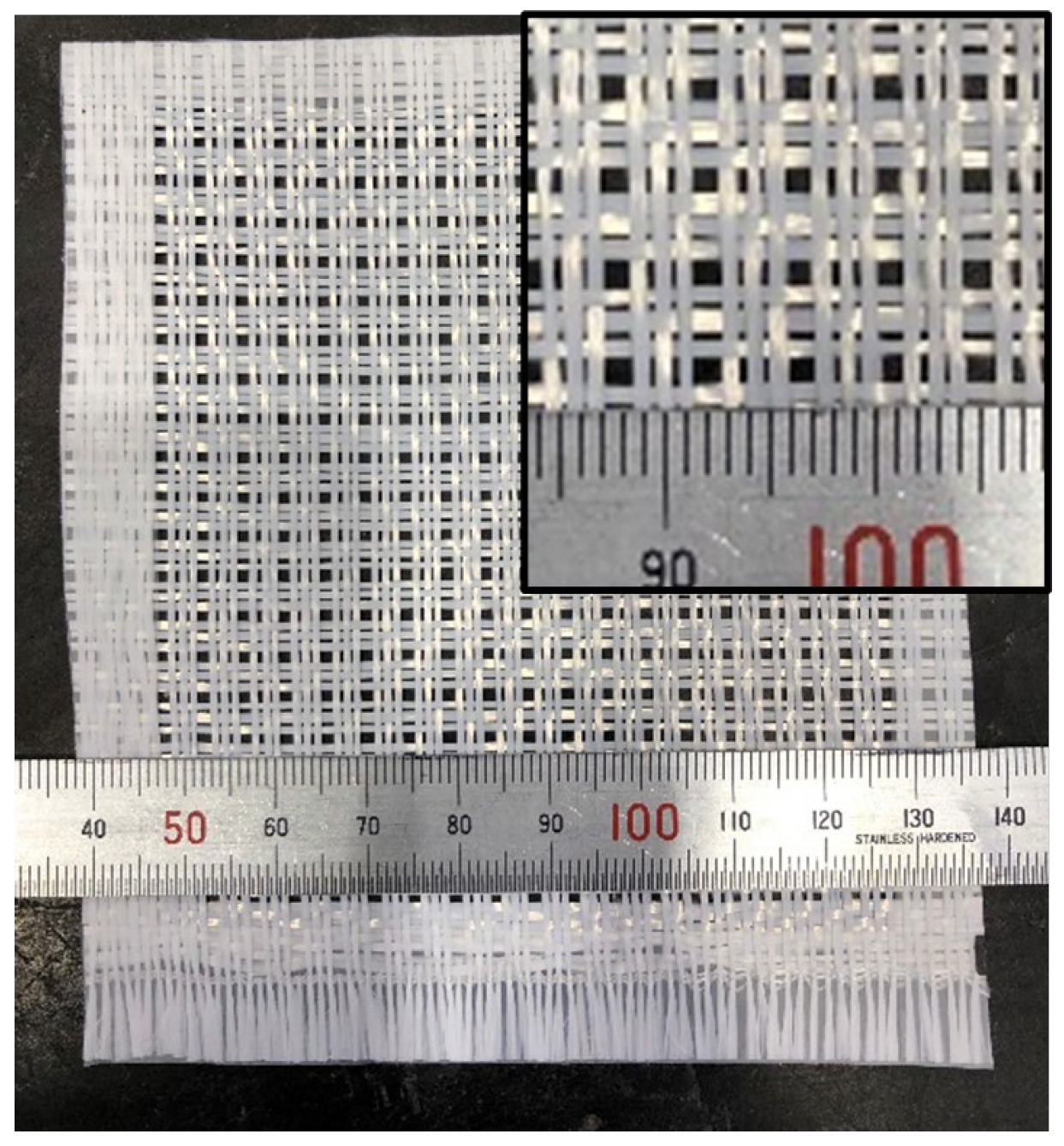
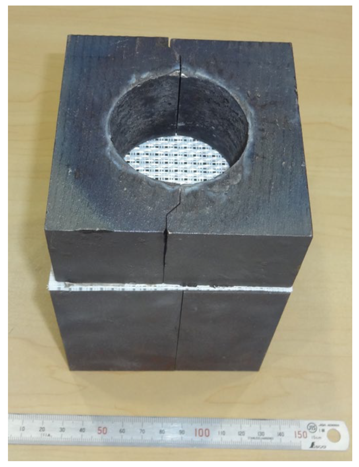
2. Method for Laboratory Prediction of Fillability of TiAl Alloy Melts in Thin-Walled Parts

Turbine wheels for passenger car turbochargers are produced via investment casting. In this process, molten metal is poured into an oxide ceramic mold. The extremely narrow ceramic spaces at the tip of the blade must be completely filled with molten metal. In general, the molten metal fillability is significantly affected by process conditions such as the superheating temperature of the molten metal and the preheating temperature of the ceramic mold. However, in water-cooled copper crucible melting, which is commonly used for the melting of TiAl alloys, the superheating temperature of the molten metal is limited because of the influence of the skull [10]. In addition, if the preheating temperature of the ceramic mold is too high, defects are likely to occur on the surface of the product because of the reaction with the ceramic mold. Therefore, it would be desirable to be able to improve the molten metal fillability in thin blades by adjusting the alloy composition without being dependent on process conditions.
The two important factors of alloy composition that affect the fillability of the molten metal are the fluidity of the molten metal and the wettability of the molten metal on the oxide ceramic. Han et al. [11] conducted centrifugal casting experiments on TiAl alloys using a spiral mold made of oxide ceramics and evaluated the fluidity of the molten metal by measuring the length reached by the molten metal. However, the oxide ceramic channels used in this experiment were trapezoidal in shape, with a top width of 2 mm, bottom width of 4 mm, and height of 3 mm, which is much wider than the tip of a turbine wheel blade, making it difficult to evaluate the wettability, which depends on the material in contact. In addition, because the process of manufacturing ceramic molds and conducting centrifugal casting trials is the same as that of investment casting of products, casting trials using the actual shape of the turbine wheel is more practical when the turbine wheel is the target.
Wettability was evaluated by Li et al. [12] by dropping molten Ti-50Al alloy onto various oxides, and it was shown that Y2O3 was the oxide with the greatest improvement in wettability of the TiAl melt. They argued that Y2O3 was the best material for the first layer of the ceramic mold used in the investment casting of TiAl alloys. However, their method cannot evaluate the fluidity of the molten metal.
In this study, we hypothesized that evaluating the amount of TiAl molten metal that passes through extremely narrow channels of an oxide ceramic material is effective in simultaneously evaluating the fluidity of molten metal and the wettability of oxide ceramics at lab scale. The technique evaluated hereafter uses an oxide ceramic mesh with many narrow gaps, mimicking the metal flow through small casting channels. The setup is inexpensive because no ceramic mold is required for the casting experiment. ZrO2 (which is far less expensive than Y2O3 and has relatively high chemical stability) or Y2O3 is the best material for this ceramic mesh. However, ZrO2 or Y2O3 fabrics made from continuous fibers are not currently available. Therefore, the method was demonstrated using a commercially available Al2O3-SiO2 fabric (Nitivy Co., Ltd., Tokyo, Japan) [13]. The material that makes up this fabric is a bundle of several thousand continuous Al2O3-SiO2 fibers approximately 10 µm in diameter, and the fabric is made by weaving these fiber bundles. The main component was Al2O3, with different ratios of SiO2, such as 1, 5, 10, 15, and 28 wt.%. Since the likelihood of chemical reaction with the TiAl melt increases as the SiO2 concentration increases, a 1 wt.% SiO2 fabric was used in this study.
The fabric has a dense structure with almost no gaps for the molten metal to pass through. Therefore, the mesh was created by pulling out the fiber bundles from the fabric. The maximum width and length of a single gap is approximately 1.5 mm, and the gap area relative to the total area can be adjusted by changing the ratio of the fiber bundles pulled out of the fabric. After examining various gap areas, the difference in the amount of molten metal passing through the mesh was significant when the gap area was approximately 20%. Figure 1 and Figure 2 show the mesh used in the experiment and the arrangement of the mesh and metal mold (cast iron) during the casting test in the laboratory, respectively. The upper mold had a molten metal passage with a diameter of 55 mm, and the lower mold had a cavity with a diameter of 60 mm. The molds were not preheated during casting experiments. Figure 3 shows a casting example, where part of the molten metal solidifies after passing through the mesh and the remaining part has solidified before passing through the mesh. The molten metal that did not pass through the mesh formed a cup that stuck to the inside of the top mold. In the casting tests of various alloys conducted in this study, the weight ratio of the molten metal passing through the mesh was measured. It was assumed that alloys with a higher pass ratio would have better molten metal fillability in thin-walled areas.

3. Materials and Methods

3.1. Laboratory Evaluation Methods for Melt Fillability and Impact Resistance

3.1.1. Materials

Table 1 presents the nominal alloy compositions. The alloys include a binary alloy, six ternary alloys with various additive elements, and various practical alloys (hereinafter referred to by the sample IDs in Table 1). The amount of additives in the ternary alloys was based on the alloying strategies of practical TiAl alloys. The raw materials used were Ti sponges; Al pellets; Cr, Mn, and Si grains; Nb flakes; W and Mo powders; and TiC alloy powders. The weight of each batch was kept constant at 770 g, and the raw materials were melted in a CaO crucible in an Ar-substituted atmosphere after evacuation using an induction melting furnace. 0.1 wt.% Ca was added in the form of an Al-10 wt.% Ca alloy for deoxidation [14]. After all the raw materials were melted, they were held for 3 min at a constant melting power (4.75 kW) for all batches and poured into two types of cast-iron molds. The first mold was used to evaluate the fillability of the molten metal in thin-walled sections, as shown in Figure 2. The second mold was used to evaluate the impact resistance to obtain castings with a flat plate having dimensions of 60 mm × 90 mm × 16 mm with a hot top. Because TiAl alloy turbine wheels are often used in the as-cast state [4] to reduce costs, as-cast material was used to perform impact resistance tests. Although the actual chemical composition was not analyzed in this study, previous studies [14] have confirmed that the actual chemical composition of TiAl alloys produced by the above method is close to the nominal composition.

3.1.2. Evaluation Method

The fillability of the molten metal in the thin-walled sections was evaluated according to the weight ratio of the molten metal that passed through the mesh, as described in Section 2. Four tests were performed for each alloy, and the average weight ratio of the molten metal passing through the mesh was used for evaluation.
Details regarding the Charpy impact test method are provided in a separate report [9]. Charpy test specimens with dimensions of approximately 10 mm × 10 mm × 55 mm were prepared by cutting and machining the as-cast material. Because TiAl alloys have low impact resistance, we used unnotched specimens and tested them with a small 50-J hammer to clarify the differences between the alloys. Test temperatures of 25 and 850 °C (assumed to be close to the maximum temperature of TiAl turbine wheels) were used to evaluate the chipping resistance of the blades in the manufacturing process and the durability of the blades against FOD in service, respectively. Charpy impact tests were performed on at least 10 specimens of each alloy at each temperature, and the impact resistance values of the alloys were compared to the average absorbed energy. The microstructure was examined using backscattered electron imaging using a JEOL JSM-6060 scanning electron microscope (JEOL Ltd., Akishima, Japan) and optical microscopy using a KEYENCE VHX-550 digital microscope (KEYENCE Ltd., Osaka, Japan). In addition, the fine precipitates produced by the reaction between Al2O3-1%SiO2 mesh and molten metal were analyzed by field-emission scanning electron microscopy (FE-SEM)/energy dispersive X-ray spectroscopy (EDS) using a ZEISS GeminiSEM 300 (ZEISS GmbH, Oberkochen, Germany)

3.2. Turbine Wheel Test Procedures

To illustrate the differences in the molten metal fillability of each alloy in thin turbine wheel blades, an investment casting test was performed using a turbine wheel shape designed for Inconel 713C with a blade tip thickness of 0.45 mm, which is very thin for TiAl alloys. The casting method was centrifugal casting, which is commonly used for TiAl alloy turbine wheels. The alloy composition of the produced turbine wheel was identical to that presented in Table 1. The casting test was performed by remelting a master alloy ingot prepared in the laboratory using the method described in Section 3.1.1. In this case, in order to ensure that the weight of the master alloy ingot for each alloy was constant (900 g) in the turbine wheel casting experiment, new ingots were made instead of casting materials (whose weight was not constant) that had passed through the mesh.
Figure 4 shows a schematic of the one-piece flow casting equipment used in this study. Here, the raw material ingot is melted in a water-cooled copper crucible, and the crucible and mold are rotated together to apply a centrifugal force to the molten metal to improve castability. A ceramic mold with Y2O3 + ZrO2 as the first layer was used and the mold preheating temperature was set as a constant (1000 °C). The molds were preheated in a furnace installed outside the casting machine. The molds for each alloy were heated simultaneously in the furnace, which was set at 1000 °C, and then the molds were removed from the furnace one by one and installed in the casting machine, where casting tests were carried out quickly. As the time required for this process was not significantly different for each alloy, it is assumed that there was not much difference in mold temperature during the casting tests.
In addition, all the process conditions, such as the weight of the raw material ingot, melting power, holding time in the molten state, and mold rotation speed, were kept constant. After investment casting, the ceramic mold was removed via hammering or sandblasting to obtain TiAl turbine wheels of each alloy. In this case, because the blades were significantly thinner than the normal TiAl turbine wheels, they were handled with care to avoid chipping.
The filling behavior of the molten metal in the thin turbine wheel blades was evaluated by calculating the volume by dividing the weight of each alloy turbine wheel by its specific weight. The specific gravity of each alloy was calculated from the mixing ratio of each element. In this case, the calculation results differed slightly from the actual specific gravity, so a correction factor was obtained by comparing the calculation results for TiAl4822 with its known specific gravity (3.97). The specific gravity of each alloy was estimated by multiplying the calculation results by this correction factor.
We also attempted to evaluate the impact resistance of the turbine wheel blades using a Charpy impact tester (Anytester, Hefei, China) and other equipment but were unable to obtain meaningful data. The variability in obtained blade thicknesses (designed to become thinner toward the tip) due to fillability differences between alloys precluded any possibility of testing the material under the same conditions.

4. Results

4.1. Molten Metal Permeability to Mesh and Impact Resistance in Laboratory

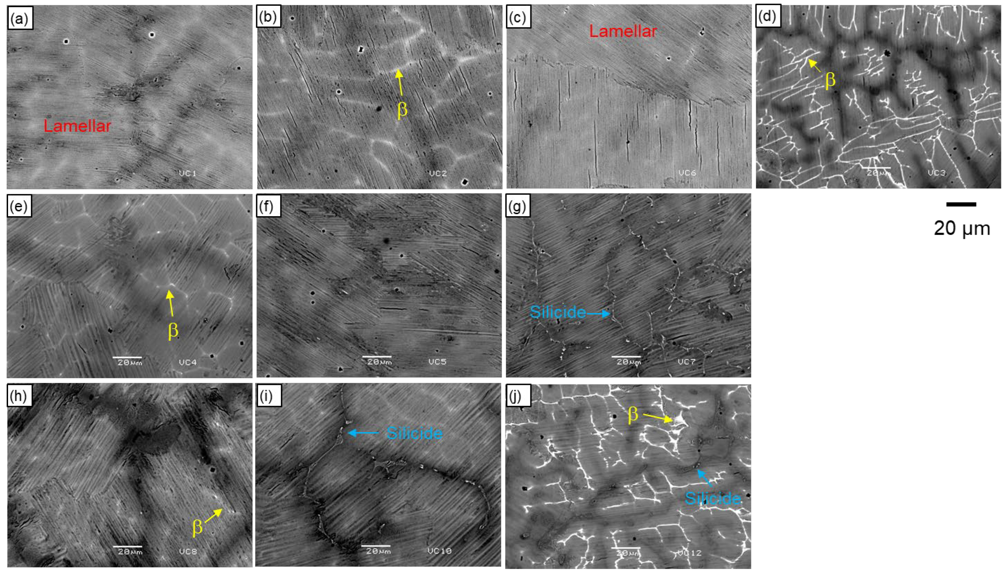
4.1.1. Microstructure

Figure 5 shows backscattered electron images of the as-cast microstructure of each alloy. All samples have a fully lamellar structure, which is common in as-cast TiAl alloys. Moreover, residual dendrite structures can be observed. Traces of the white phase (i.e., the primary β-phase) are in this dendritic structure and are pronounced in 2W (46.5Al-2.0W) and ABB (46.0Al-2.0W-1.0Si) [15], which contain the strong β-stabilizing element W. In addition, traces of β-phase were observed in 2Cr (46.5Al-2.0Cr), 4822 (48.0Al-2.0Nb-2.0Cr) [1], and 5Nb (46.5Al-5.0Nb), which contained the β-stabilizing elements Cr (slightly strong effect) and Nb (small effect). Meanwhile, silicide precipitation [16] was observed in the Si-added materials 1Si (46.5Al-1.0Si) and DAT2, as well as in ABB.

4.1.2. Molten Metal Permeability to Mesh

Figure 6 shows the average weight ratio of the molten metal passing through the mesh for each alloy. The minimum and maximum values for each of the four tests are presented. Comparing the alloy systems, the passing ratio of Binary (46.5 Al) is the largest, and that of practical alloys is the smallest. For all ternary alloys, the ratio was lower than that of the Binary, and the decrease was pronounced for 1Si and 2Cr. Because all practical alloys contain Si (DAT2 and ABB) or Cr (TiAl4822 and DAT2), the amount of molten metal passing through the mesh is reduced owing to the influence of these added elements.

4.1.3. Impact Resistance at 25 and 850 °C

Figure 7 shows the average absorbed energy in Charpy impact tests at 25 and 850 °C for the as-cast state of each alloy. The absorbed energy at 850 °C exceeds that at 25 °C for all alloys, which may be due to the improvement in ductility as the temperature increases. When each ternary alloy is compared with the Binary at 25 °C, the absorbed energy with 2Cr and 2Mn addition increases, indicating improved impact resistance. This result is consistent with a previous study [9]. However, the absorbed energies with 5Nb, 0.8Mo, 2W, and 1Si addition decreased. The low absorbed energy with these elements is also consistent with the previous study [9]. For 2W, the amount of W added was high, and the large amount of β-phase, which is detrimental to the impact resistance of TiAl alloy [14], appears clearly in Figure 5. Practical alloys 4822, which contain 2Cr, are comparable to Binary, but DAT2 and ABB have lower impact resistances because they contain Si, which significantly reduces impact resistance. At 850 °C, the relative relationship between the alloys is the same as at 25 °C, but the increase in absorbed energy for 2Cr, 4822, and DAT2 exceeds those for the others. This is attributed to the high-temperature ductility improvement effects of Cr, which is common in these alloys.

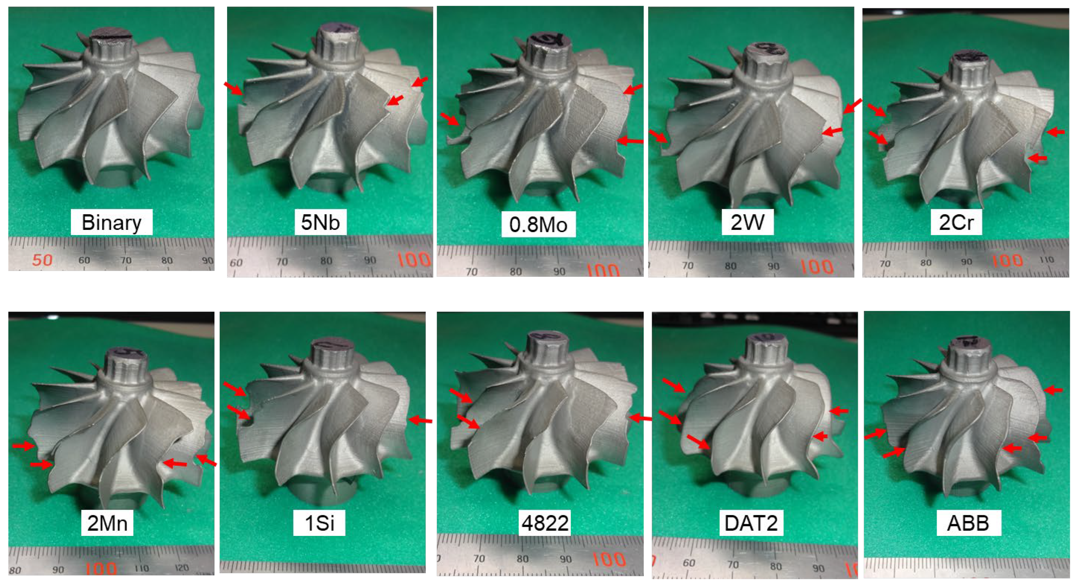
4.2. Validation of Results Using Turbine Wheel Casting

Figure 8 shows the turbine wheels made with each alloy. The blades indicated by the red arrows are examples of blades that have not been filled with molten metal. The Binary is the best, and almost all blades are filled with molten metal. However, in ternary and practical alloys, many blades are not filled with molten metal. Figure 9 shows the volume fill ratio calculated from the weight of each alloy turbine wheel based on Binary. The Binary exhibited the highest ratio relative to the ternary and practical alloys. In ternary alloys, the decrease observed for 5Nb and 2W was small, whereas the decrease for 2Cr and 2Mn was large. The decrease for 1Si was not as extreme as that of the mesh pass ratio, as shown in Figure 6. Moreover, the volume-fill ratio of the practical alloys was significantly lower than that of the Binary.
Compared to the mesh permeability test (Figure 6), the results are not completely reproduced, but there is considerable agreement, such as the fact that Binary performs best, the practical alloys perform poorly, and that Cr reduces both mesh permeability and volume fill rate in the turbine wheel. Thus, the effect of composition on the molten metal fillability of the TiAl turbine wheel can be roughly captured by conducting mesh pass-through experiments at the lab scale.

5. Discussion

5.1. Effect of Composition on Molten Metal Fillability in Thin Turbine Wheel Blades

The effects of the molten metal superheating temperature and ceramic mold preheating temperature are significant in the investment casting of TiAl alloys, and the castability is expected to improve with increases in these temperatures [17,18]. In the turbine wheel casting test used in this study, the mold preheating temperature was maintained constant; therefore, the differences shown in Figure 9 may have been caused by the difference in the superheating temperature of the molten metal. However, the molten metal temperature was not measured owing to equipment limitations, and the superheating temperature was not accurately evaluated. Nevertheless, the raw material ingot weight, melting power, and melting time were set constant for each alloy, and the molten metal temperature should not differ significantly. Thermodynamic simulations were performed with the Thermo-Calc Software and the TCTI5 database (Titanium and TiAl-based Alloys Databases, version 5) to evaluate the liquidus temperature of each alloy. Assuming no significant difference in molten metal temperature, a lower liquidus corresponds to a higher superheat temperature. Figure 10 shows the liquidus temperatures of each alloy added to Figure 9 (the volume filling ratio of the turbine wheel of each alloy based on the Binary). The liquidus temperature of the Binary, which had the highest volume fill ratio, was in the middle. Moreover, the volume fill ratio of 4822, which had the lowest liquidus temperature (i.e., the highest superheating temperature), was low. Thus, the superheating temperature of the molten metal has a small effect on the volume-fill ratio of the turbine wheel.
Furthermore, the fluidity of the molten metal decreases as the solidus–liquidus range increases in titanium alloys [19]. In their evaluation of the castability of TiAl4822 with B using a spiral-shaped ceramic mold, Han et al. [11] concluded that the fluidity of the molten metal improved owing to the narrowing of the solidus–liquidus range upon the addition of B. Therefore, the solidus–liquidus range for each alloy used in our turbine wheel casting was calculated in the same way using the Thermo-Calc TCTI5 database, as shown in Figure 11. The results correspond to the actual situation, with the Binary having the narrowest solidus–liquidus range and the largest molten metal fill ratio. Conversely, ABB has the widest range and smallest volume fill ratio. However, 2Cr and 2Mn have a low molten metal fill ratio while having an intermediate solidus–liquidus range. This suggests contributions from other factors.
In addition to the solidus–liquidus range, the contribution of the wettability of the TiAl alloy molten metal to the oxide ceramics was also considered. Cheng et al. [20] showed that the wettability of TiAl alloys is improved with oxide ceramics, which have low reactivity with molten TiAl alloys. The correlation between the mesh permeability in the laboratory and the volume fill ratio of the turbine wheel was confirmed in this study. Therefore, microstructures near the mesh were observed after the molten metal mesh pass-through test. Figure 12 shows the optical micrographs for Binary, 2Cr and DAT2 as representative examples. In the case of the Binary, where the molten metal had good mesh permeability, almost no reaction layer was formed. In the case of 2Cr, where the permeability was lower than that of the Binary, a reaction layer with many precipitates was formed. Meanwhile, DAT2 had the lowest mesh permeability and a wide reaction layer with even more precipitates. The results of the analysis of the microstructure near the mesh of 2Cr using FE-SEM/EDS are shown in Figure 13. Two types of precipitates were observed, produced by the reaction between the mesh and the molten metal. The first type is an Al-rich oxide, as oxygen is concentrated at the same level as Al2O3-1%SiO2 fibers, and there is almost no Ti. The second type is thought to be an α2 phase stabilized by oxygen, as oxygen is slightly concentrated and Al is reduced. These precipitates are thought to have been formed as a result of the decomposition of some of the Al2O3-1%SiO2 mesh due to reaction with the molten metal and the resulting oxygen contamination.
Therefore, the composition-dependent wettability to oxide ceramics, in addition to the solidus–liquidus range, has a significant impact on the differences in mesh permeability and fillability of turbine wheel blades.

5.2. Evaluation of Existing Practical TiAl Alloys and Potential for Development of New Alloys

The molten metal fillability and impact resistance of DAT2 (Ti-46.5Al-3.2Nb-0.8Cr-0.7Si-0.1C)—the only alloy used for current turbine wheels for passenger car turbochargers—were among the lowest of all the alloys examined. This is due to the presence of Cr and Si, which negatively affect the molten metal fillability, and Nb, Si, and C (C is the result of previous study [9]), which deteriorate the impact resistance. Hence, the currently used TiAl alloy is not the most suitable for turbine wheels for passenger car turbochargers.
On the other hand, TiAl4822 (Ti-48.0Al-2.0Nb-2.0Cr) is not used for turbine wheels but is being mass-produced as blades for jet engines. Since contemporary jet engine blades are not made by near-net-shape casting but by machining ingots [21] and cast materials with a large amount of excess material [22], their low castability (due to Cr addition) is not a major problem. In addition, as shown in this study and a previous report [9], Cr improves impact resistance, making it a very useful element for improving reliability. Thus, TiAl4822 is an excellent alloy for jet engine blades for which castability is not a major consideration. In addition, ABB and other practical alloys not investigated in this study, such as 45, 47XD (Ti-45.0, 47.0Al-2.0Nb-2.0Mn-0.8 vol% TiB2) [23], TNM (Ti-43.5Al-4.0Nb-1.0Mo-0.1B) [24], TNB-V2 (Ti-45.0Al-8.0Nb-0.2C) [25], and RNT650 (Ti-48.1Al-2.0Nb-0.7Cr-0.3Si) [3], most of which contain Nb, W, Mo, Cr, Mn, Si or C, have poor molten metal fillability and/or impact resistance. Hence, they are not suitable for thin-blade turbine wheels for passenger car turbochargers.
The operating temperature of turbine wheels exceeds that of jet engine blades. Thus, the oxidation resistance and creep strength are key design parameters, and the addition of Nb [26,27]/W [28,29] (oxidation resistance) and Si [30,31]/C [32,33] (creep strength) is essential. However, as indicated by this study, the addition of these elements inevitably reduces the molten metal fillability and impact resistance of the material. The addition of Cr or Mn improves impact resistance but reduces the molten metal fillability. These findings explain the difficulty of introducing a new TiAl alloy for thin-blade turbine wheels.
The only way to improve the potential for the development of new TiAl-based thin-blade turbine wheels is to minimize the amount of each element added, i.e., Nb/W for oxidation resistance, Si/C for creep strength, and Cr/Mn for impact resistance. If the minimum amounts of these elements are added to satisfy the application requirements, a better balance between molten metal fillability and/or impact resistance can be achieved. However, if the operating temperature of TiAl turbine wheels is increased from the present level, it will be necessary to investigate other alloying strategies.

6. Conclusions

The effects of alloy composition on the molten metal fillability and impact resistance of the thin blades of TiAl alloy turbine wheels for passenger car turbochargers were predicted through simple laboratory experiments and verified using actual turbine wheels. The effect of alloy composition on the molten metal fillability obtained by passing molten metal through an Al2O3-1 wt.% SiO2 mesh is consistent with results from actual turbine wheels. The molten metal fillability of thin-walled parts is best for the binary alloy and decreases when Cr, Mn, and Si are added. Furthermore, the change in solidus–liquidus range and wettability to the oxide ceramics due to the alloy composition affected the molten metal fillability of the thin turbine wheel blades. The addition of Cr and Mn improved the impact resistance, while the addition of Nb, Mo, W and Si reduced it. Because most practical TiAl alloys contain such elements owing to other requirements, their melt fillability and/or impact resistance is poor.
Future developments of new TiAl alloys for thin-blade turbine wheels require optimization of the number of elements added, taking into account not only oxidation resistance and creep strength but also molten metal fillability and impact resistance. The proposed method can promote such developments.

Author Contributions

Conceptualization, T.T.; methodology, T.T.; software, T.V. and P.S.; validation, T.T. and Y.-Y.L.; formal analysis, T.V. and P.S.; investigation, T.T. and Y.-Y.L.; resources, T.T.; data curation, T.T., Y.-Y.L., T.V. and P.S.; writing—original draft preparation, T.T.; writing—review and editing, Y.-Y.L., T.V. and P.S.; visualization, T.T.; supervision, T.T.; project administration, T.T.; funding acquisition, T.T. All authors have read and agreed to the published version of the manuscript.

Funding

This research was funded by the Japan Science and Technology Agency, grant number AS0216001.

Data Availability Statement

The original contributions presented in this study are included in the article. Further inquiries can be directed to the corresponding authors.

Conflicts of Interest

Author Yu-Yao Lee was employed by FuSheng Precision Co., Ltd. Authors Thomas Vaubois and Pierre Sallot were employed by Safran Tech, Materials and Processes. The remaining author declares that the research was conducted in the absence of any commercial or financial relationships that could be construed as a potential conflict of interest.

References

  1. Bartolotta, P.; Barrett, J.; Kelly, T.; Smashey, R. The use of cast Ti-48Al-2Cr-2Nb in jet engines. JOM 1997, 49, 48–50. [Google Scholar] [CrossRef]
  2. Bewlay, B.P.; Nag, S.; Suzuki, A.; Weimer, M.J. TiAl alloys in commercial aircraft engines. Mater. High Temp. 2016, 33, 549–559. [Google Scholar] [CrossRef]
  3. Noda, T. Application of cast gamma TiAl for automobiles. Intermetallics 1998, 6, 709–713. [Google Scholar] [CrossRef]
  4. Koyanagi, Y.; Sumi, Y.; Takabayashi, H. Development of titanium aluminide alloy with good high temperature properties for turbine wheel. Denki Seiko 2014, 85, 121–125. (In Japanese) [Google Scholar]
  5. Tetsui, T. Development of a TiAl turbocharger for passenger vehicles. Mater. Sci. Eng. A 2002, 329–331, 582–588. [Google Scholar] [CrossRef]
  6. AeroEdge. AeroEdge Was Invited to the Ceremony for Celebrating the Delivery of One Million TiAl Blades. Available online: https://aeroedge.co.jp/en/news/newsrelease/857/ (accessed on 23 January 2025).
  7. Kim, S.-W.; Hong, J.K.; Na, Y.-S.; Yeom, J.-T.; Kim, S.E. Development of TiAl alloys with excellent mechanical properties and oxidation resistance. Mater Des. 2014, 54, 814–819. [Google Scholar] [CrossRef]
  8. Kawaura, H.; Nishino, K.; Saito, T. Effects of alloying elements on foreign object damage resistance of cast-TiAl base alloys. J. Jpn. Inst. Met. 2002, 66, 451–458. (In Japanese) [Google Scholar] [CrossRef]
  9. Tetsui, T. Selection of additive elements focusing on impact resistance in practical TiAl cast alloys. Metals 2022, 12, 544. [Google Scholar] [CrossRef]
  10. Harding, R.A.; Wickins, M. Temperature measurements during induction skull melting of titanium aluminide. Mater. Sci. Technol. 2003, 19, 1235–1246. [Google Scholar] [CrossRef]
  11. Han, J.; Liu, Z.; Jia, Y.; Wang, T.; Zhao, L.; Guo, J. Effect of TiB2 addition on microstructure and fluidity of cast TiAl alloy. Vacuum 2020, 174, 109210. [Google Scholar] [CrossRef]
  12. Li, B.S.; Liu, A.H.; Nan, H.; Bi, W.S.; Guo, J.J.; Fu, H.Z. Wettability of TiAl alloy melt on ceramic moulds in electromagnetic field. Trans. Nonferrous Met. Soc. China 2008, 18, 518–522. [Google Scholar] [CrossRef]
  13. Nitivy. Heat-Resistant Fiber Nitivy ALF™. Available online: https://www.nitivy.co.jp/en/products/alf/ (accessed on 16 January 2025).
  14. Tetsui, T.; Mizuta, K. Detrimental effects of βo-phase on practical properties of TiAl Alloys. Metals 2024, 14, 908. [Google Scholar] [CrossRef]
  15. Lapin, J.; Nazmy, M. Microstructure and creep properties of a cast intermetallic Ti–46Al–2W–0.5Si alloy for gas turbine applications. Mater. Sci. Eng. A 2004, 380, 298–307. [Google Scholar] [CrossRef]
  16. Xu, Q.; Fang, H.; Wu, C.; Wang, Q.; Cui, H.; Chen, R. Microstructure evolution and its effect on mechanical properties of cast Ti48Al6NbxSi alloys. China Foundry 2020, 17, 416–422. [Google Scholar] [CrossRef]
  17. Kuang, J.P.; Harding, R.A.; Campbell, J. Examination of defects in gamma titanium aluminide investment castings. Int. J. Cast Met. Res. 2000, 13, 125–134. [Google Scholar] [CrossRef]
  18. Kim, M.-G.; Sung, S.-Y.; Kim, Y.-J. Microstructure, metal-mold reaction and fluidity of investment cast-TiAl alloys. Mater Trans. 2004, 45, 536–541. [Google Scholar] [CrossRef]
  19. Watanabe, K.; Miyakawa, O.; Takada, Y.; Okuno, O.; Okabe, T. Casting behavior of titanium alloys in a centrifugal casting machine. Biomaterials 2003, 24, 1737–1743. [Google Scholar] [CrossRef]
  20. Cheng, X.; Yuan, C.; Green, N.; Withey, P. Evaluation of the inertness of investment casting molds using both sessile drop and centrifugal casting methods. Metall. Mater. Trans. A 2013, 44, 888–898. [Google Scholar] [CrossRef]
  21. Güther, V.; Allen, M.; Klose, J.; Clemens, H. Metallurgical processing of titanium aluminides on industrial scale. Intermetallics 2018, 103, 12–22. [Google Scholar] [CrossRef]
  22. Brotzu, A.; Felli, F.; Mondal, A.; Pilone, D. Production issues in the manufacturing of TiAl turbine blades by investment casting. Procedia Struct. Integr. 2020, 25, 79–87. [Google Scholar] [CrossRef]
  23. Larsen, D.E.; Christodoulou, L.; Kampe, S.L.; Sadler, R. Investment-cast processing of XDTM near-γ titanium aluminides. Mater. Sci. Eng. A 1991, 144, 45–49. [Google Scholar] [CrossRef]
  24. Bernal, D.; Chamorro, X.; Hurtado, I.; Lopez-Galilea, I.; Bürger, D.; Weber, S.; Madariaga, I. Integration of hot isostatic pressing and heat treatment for advanced modified γ-TiAl TNM alloys. Materials 2022, 15, 4211. [Google Scholar] [CrossRef] [PubMed]
  25. Szkliniarz, W.; Szkliniarz, A. The characteristics of TiAl-based alloys melted in graphite crucibles. Mater. Sci. Technol. 2019, 35, 297–305. [Google Scholar] [CrossRef]
  26. Xu, X.; Liang, H.; Ding, H.; Davidson, K.P.; Ramanujan, R.V.; Chen, R.; Guo, J.; Fu, H. Oxidation behavior and mechanical properties of a directionally solidified high Nb TiAl based alloy between 800 °C and 900 °C. Intermetallics 2025, 176, 108538. [Google Scholar] [CrossRef]
  27. Feng, L.; Li, B.; Li, Q.; Gao, Y.; Pei, Z.; Liang, C. Enhancement of mechanical properties and oxidation resistance of TiAl alloy with addition of Nb and Mo alloying elements. Mater. Chem. Phys. 2024, 316, 129148. [Google Scholar] [CrossRef]
  28. Zhao, P.; Ma, H.; Li, X.; Gao, M.; Ma, Y.; Liu, K. Insights into the role of W/B alloying on high-temperature oxidation behavior of Ti42Al5Mn alloy. J. Mater. Sci. Technol. 2024, 178, 188–200. [Google Scholar] [CrossRef]
  29. Shida, Y.; Anada, H. Role of W, Mo, Nb and Si on oxidation of TiAl in air at high temperatures. Mater. Trans. JIM 1994, 35, 623–631. [Google Scholar] [CrossRef]
  30. Fröbel, U.; Stark, A.; Paul, J.; Pyczak, F. Assessment of the capability of Zr, Y, La, Gd, Dy, C, and Si to enhance the creep strength of gamma titanium aluminide alloys based on their effect on flow stress and thermal activation parameters. Intermetallics 2023, 162, 108018. [Google Scholar] [CrossRef]
  31. Du, X.-W.; Wang, J.N.; Zhu, J. The influence of Si alloying on the crept microstructure and property of a TiAl alloy prepared by powder metallurgy. Intermetallics 2001, 9, 745–753. [Google Scholar] [CrossRef]
  32. Kamyshnykova, K.; Lapin, J.; Pelachová, T.; Cegan, T.; Jurica, J.; Volodarskaja, A. Microstructure and mechanical properties of Ti–45Al–2W–xC alloys. Intermetallics 2022, 148, 107618. [Google Scholar] [CrossRef]
  33. Song, L.; Hu, X.; Wang, L.; Stark, A.; Lazurenko, D.; Lorenz, U.; Lin, J.; Pyczak, F.; Zhang, T. Microstructure evolution and enhanced creep property of a high Nb containing TiAl alloy with carbon addition. J. Alloys Compd. 2019, 807, 151649. [Google Scholar] [CrossRef]
Figure 1. Al2O3-1 wt.% SiO2 mesh used in the molten metal pass-through test.
Metals 15 00474 g001
Figure 2. Arrangement of the mesh and metal mold during the casting test.
Metals 15 00474 g002
Figure 3. Examples of molten metal that has solidified after passing through the mesh and molten metal that has not passed through the mesh as viewed from the (a) side and (b) above.
Metals 15 00474 g003
Figure 4. Schematic of the equipment used to cast TiAl turbine wheels.
Metals 15 00474 g004
Figure 5. Backscattered electron images showing the as-cast microstructure of each alloy: (a) Binary; (b) 5Nb; (c) 0.8Mo; (d) 2W; (e) 2Cr; (f) 2Mn; (g) 1Si; (h) 4822; (i) DAT2; and (j) ABB.
Metals 15 00474 g005
Figure 6. Average weight ratio of molten metal that passed through the mesh for each alloy.
Metals 15 00474 g006
Figure 7. Average absorbed energy in Charpy impact tests at 25 and 850 °C for as-cast material of each alloy.
Metals 15 00474 g007
Figure 8. Appearance of the turbine wheels for each alloy.
Metals 15 00474 g008
Figure 9. The volume fill ratio of turbine wheels for each alloy is based on the binary.
Metals 15 00474 g009
Figure 10. Liquidus temperatures of each alloy were calculated using the Thermo-Calc TCTI5 database (added to Figure 9).
Metals 15 00474 g010
Figure 11. Solidus–liquidus range of each alloy was calculated using the Thermo-Calc TCTI5 database (added to Figure 9).
Metals 15 00474 g011
Figure 12. Microstructure near the mesh after the mesh pass-through test of each molten alloy: (a) Binary; (b) 2Cr; and (c) DAT2.
Metals 15 00474 g012
Figure 13. Field-emission scanning electron microscope images and energy-dispersive X-ray mapping results of the near the mesh of 2Cr.
Metals 15 00474 g013
Table 1. Compositions of the alloys tested in this study.
SystemSample IDNominal Composition (at.%)
TiAlNbMoWCrMnSiC
Binary alloyBinaryBal.46.5
Ternary alloys5NbBal.46.55.0
0.8MoBal.46.5 0.8
2WBal.46.5 2.0
2CrBal.46.5 2.0
2MnBal.46.5 2.0
1SiBal.46.5 1.0
Practical alloys4822Bal.48.02.0 2.0
DAT2Bal.46.53.2 0.8 0.70.1
ABBBal.46.0 2.0 1.0
Disclaimer/Publisher’s Note: The statements, opinions and data contained in all publications are solely those of the individual author(s) and contributor(s) and not of MDPI and/or the editor(s). MDPI and/or the editor(s) disclaim responsibility for any injury to people or property resulting from any ideas, methods, instructions or products referred to in the content.

