Article

Stress Determination by IHD in Additively Manufactured Austenitic Steel Samples: A Validation Study

by
João Paulo Nobre
1,2,*,
Maria José Marques
2,3 and
António Castanhola Batista
2
1
Univ Coimbra, Department of Mechanical Engineering, 3030-788 Coimbra, Portugal
2
Univ Coimbra, CFisUC, Department of Physics, 3004-516 Coimbra, Portugal
3
Department of Chemical and Biological Engineering, Faculty of Engineering, University of Porto, 4200-465 Porto, Portugal
*
Author to whom correspondence should be addressed.
Metals 2025, 15(5), 485; https://doi.org/10.3390/met15050485
Submission received: 1 March 2025 / Revised: 17 April 2025 / Accepted: 22 April 2025 / Published: 25 April 2025

Abstract

:
The present work aims to verify whether the incremental hole-drilling technique (IHD), a widely accepted technique, is suitable for determining residual stresses in AISI 316L samples obtained by selective laser melting (SLM). The thermo-mechanical effects of cutting during the application of this technique can induce unwanted residual stresses due to the relatively low thermal conductivity of this material, leading to erroneous results. To accomplish this aim, a hybrid experimental-numerical method was implemented to analyze the ability of IHD to determine an imposed stress state. Experimentally, samples were subjected to a tensile calibration stress using a horizontal tensile test machine. To eliminate pre-existing residual stress, the samples were subjected to differential loads, instead of absolute ones. In this way, experimental strain-depth relaxation curves related to the imposed calibration stress were obtained. Based on the experimental data, IHD was numerically simulated using the finite element method. Numerical strain-depth relaxation curves, related to the same calibration stress used in the experimental study, were obtained. The comparison between the experimental and numerical strain-depth relaxation curves, as well as the stresses calculated using the so-called integral method for determining stresses via IHD, shows that IHD is a suitable technique for measuring residual stresses in additively manufactured AISI 316L samples.

Graphical Abstract

1. Introduction

Additive manufacturing, such as selective laser melting (SLM), is becoming an unavoidable manufacturing technology for complex mechanical parts, playing an essential role in the current fourth industrial revolution [1,2]. However, this process uses the high-power thermal energy of a laser to selectively melt a metallic powder, imposing steep and localized thermal gradients, which lead to high residual stresses [3,4]. The reliable determination of such internal stresses is, therefore, essential. In this context, the incremental hole-drilling technique (IHD) is a widely accepted semi-destructive mechanical technique for measuring residual stresses [5,6], among other destructive mechanical methods, such as ring core [7], deep hole-drilling [8], the slitting method [9], or the contour method [10], in addition to non-destructive techniques, such as diffraction, ultrasonic, and magnetic [11]. However, there are currently few published works on the experimental determination of residual stresses in additively manufactured austenitic steels, with the majority of published research being based on diffraction methods [12,13,14,15,16,17,18], while there are very few published works based on mechanical methods, for example, using hole-drilling [19] and the contour method [20]. A recent review on AISI 316L produced by additive manufacturing can be found in reference [21]. IHD consists of incrementally drilling a small hole at the material’s surface, typically of 1–3 mm diameter, and measuring the strain relaxation due to the hole’s presence using three-strain gauge rosettes [5] or optical techniques [22] after each incremental depth. Based on the obtained strain-depth relaxation curves, in-depth non-uniform residual stress distribution, up to a depth equal to half of the hole diameter, can be determined using the so-called integral method [5,22], combined with smoothing numerical methods, such as Tikhonov regularization, to decrease uncertainties in the IHD residual stress results [5,23].
However, several issues can affect the accuracy of the residual stress determined by IHD. To avoid typical measurement errors (such as uncertainties related to the material properties, hole eccentricities, border effects, strain, hole diameter, and incremental depth), there are two significant issues that should be considered. First is the so-called plasticity effect, which can affect the IHD residual stress results when the existing equivalent residual stress is higher than about 60% of the material yield strength, once the relation between the measured strain relief and the calculated residual stress is based on the Theory of Elasticity [24]. Second, the local thermomechanical effects of friction and plastic deformation during the IHD cutting operation, when this technique is applied in difficult-to-machine materials, can affect its residual stress results. Materials presenting low thermal conductivity, high specific heat, and high strain hardening are usually included in this category [25]. This issue is the main focus of the present work, for which an experimental-numerical study was conducted to evaluate the ability of the IHD to determine a well-known applied stress to AISI 316L samples obtained by SLM and, in this way, its ability to determine residual stresses in this material, if those thermomechanical effects do not affect the IHD results.
In the early stages of the IHD technique development, several attempts to determine the induced drilling stresses during the machining operation in metals were performed. In 1982, to avoid these unwanted residual stresses during the application of IHD to metals and their alloys, Flaman proposed a pressurized air turbine for ultra-high-speed milling [26], which is currently used by all commercially available equipment for IHD. Usually, suitable thermal treatments are applied to relieve residual stresses and achieve an initial “stress-free” state. Flaman and Herring [27] studied four hole-producing techniques and roughly estimated the “stress-free” state, observing that unwanted stress of ~9 MPa in aluminum and austenitic steels was introduced by ultra-high-speed milling, while in ferritic steels, it was almost negligible (~1 MPa). Traditional milling or drilling, on the other hand, can induce very high residual stresses, which could attain the material’s yield stress [26,27]. However, it is important to note that these studies were conducted using uniform residual stress calculation, as per the ASTM standard (81’s version) [5]. Despite its excellent spatial resolution, due to its high sensitivity to measurement errors and its propagation [28], using non-uniform residual stress calculations by the integral method can make the values mentioned above much higher [24]. Therefore, it is necessary to conduct the present research using the integral method to determine a well-known and applied stress state to the austenitic steel samples obtained by SLM, since this method is currently the standard method to determine non-uniform residual stresses by IHD.
Similar approaches to study induced drilling stresses during hole-drilling were investigated further by Weng et al. [29] using samples cut by electric discharge machining (EDM). Subsequently, Lee et al. [30] proposed a correction formula for the EDM hole-drilling strain gauge method for measuring residual stress. According to their findings, for the AISI 316L steel, even though SLM parameters and generated porosity can influence the final thermal conductivity (k) of the material [31], one can expect an induced residual stress around 60 MPa (k ∈ ]12, 15[ W/(m⋅K) [31]). Simmons et al. [31] also observed that the unique thermal profile of SLM changes the microstructure relative to traditionally processed materials and alters the thermal conductivity locally of additively manufactured 316L stainless steel.
All the approaches mentioned above to study drilling-induced stresses are qualitative and can only provide a rough estimate of induced drilling stresses during IHD, due to the physical impossibility of obtaining an utterly stress-free state using thermal treatments. In addition, these approaches cannot be applied to fiber-reinforced polymers, where possible thermal damage to the matrix and the mismatch in the thermal expansion coefficients of the constituents prohibit their application. A hybrid experimental-numerical method (HENM) was proposed to overcome these difficulties in carbon fiber-reinforced polymers [32] and was recently used in fiber metal laminates [33].
There are few studies on the experimental validation of the IHD technique in general, and there are no experimental studies demonstrating the ability of the IHD technique, using the integral method, to determine stresses in additively manufactured austenitic steels. Therefore, the HENM method, which is explained in the next section, was applied to AISI 316L samples manufactured by SLM. The findings were analyzed and discussed considering the implemented experimental parameters and conditions, thus demonstrating the ability of the IHD technique for measuring residual stresses in these materials.

2. The Hybrid Experimental-Numerical Method (HENM)

The hybrid experimental-numerical method (HENM) is based on an initial experimental phase, followed by a final numerical phase.
Experimentally, samples of the test material are subjected to a well-known applied tensile load (calibration load) using a purpose-built horizontal tensile test machine. Incremental hole-drilling is performed on the samples under load, and strain-depth relaxation curves are obtained. However, these curves correspond to the strain relaxation due to the calibration stress, superimposed on the residual stresses existing in the material, that is, those existing before drilling and on the possible unwanted stresses induced by the thermomechanical effects of friction and plastic deformation during IHD milling operation. However, the existing residual stresses can effectively be eliminated using a differential calibration load (stress) instead of an absolute one. Provided that there is no plastic yielding during the process, using the superposition principle, it is possible to observe that maximum and minimum stresses, σmax and σmin, on a given sample subjected to uniaxial stresses, σ c a l m a x and σ c a l m i n , considering the existing residual stresses, σrs, is given by:
σ m a x = σ r s + σ c a l m a x σ m i n = σ r s + σ c a l m i n σ = σ m a x σ m i n = σ c a l .
Therefore, if the IHD procedure is performed under Δσ, the effect of the existing residual stress on the experimentally measured strain-depth relaxation curves can be avoided. There are two possible approaches to carry out the experimental study. First, the samples are incrementally drilled under the minimum load to obtain the corresponding strain-depth relaxation curves. After each incremental depth and strain measurement, the load is increased to the maximum value and the strain is recorded again. The procedure is repeated depending on the necessary number of increments. Two sets of experimental strain-depth relaxation curves for the maximum and minimum applied loads are obtained. The difference between both will provide the strain depth relaxation curves corresponding to the differential calibration stress, Δσ. The main disadvantage of this approach is the necessity of recentering the mill on the exact position of the drilled hole after the loading and unloading process to perform the next incremental depth exactly at the same position. The second approach is to conduct the incremental hole-drilling twice, i.e., for the maximum and minimum load. This approach avoids the necessary recentering procedure of the first approach. However, it is necessary to drill the hole in two adjacent positions and to expect that there is a similar residual stress state in both positions. This approach can only be applied if there is no stress gradient between the two drilling positions. In this work, once X-ray diffraction residual stress results, determined at material’s surface, have shown a uniform residual stress state along the central region of the samples, where IHD would be performed and, therefore, it was decided to follow the second approach.
Numerically, considering all data of the experimental phase, IHD is simulated on a modelled sample subjected to the calibration stress, using the finite element method. Numerical strain-depth relaxation curves, corresponding to the hole simulation on the modelled specimen subjected to the same loading, can, therefore, be obtained. However, the hole simulation is carried out by removing elements from the FEM model, and therefore, the obtained curves can be considered theoretically ideal, since they are due to the applied calibration stress only. The direct comparison between the experimental and numerical curves allows the evaluation of the effect of the cutting procedure itself and the applicability of IHD to the test material. Moreover, the experimental and numerical strain-depth relaxation curves can be used as input for the unit pulse integral method for non-uniform residual stress calculation by IHD. This way, it is also possible to verify the ability of the incremental hole-drilling technique to determine the calibration stress applied to the additively manufactured AISI 316L samples.

3. The Integral Method for IHD Stress Calculation

IHD consists of incrementally drilling a small hole at the material’s surface, typically 1–3 mm in diameter, and measuring the surface strain relaxation around the hole after each incremental depth. To completely define the plane stress state at each depth increment, a typical standard three-gauge rosette is commonly used [5]. Thus, after hole-drilling, a set of three strain-depth relaxation curves is obtained. However, existing residual stresses at each incremental depth cannot be directly calculated from the strain relief measured at the surface. First, the decrease in the sensitivity of strain gauge measurement when the hole depth increases can be overcome by using a wise calibration procedure. Second, several calculation methods were proposed to accurately determine the residual stresses based on the incremental hole-drilling data, strain gauge rosette used, and calibration procedure. Among the four main methods proposed, Schajer [34] pointed out that the so-called integral method is theoretically the most correct since the method considers that the strain relaxation measured at the material’s surface is the accumulated result of the residual stresses originally existing in the region of each successive increment along the total hole depth, i.e., the contributions to the total measured strain relaxations of the stresses at all depths are considered simultaneously. Mathematically, the general formulation of the integral method can be written as [34,35]:
ε h = 0 h g t , h σ t d t      0 t h ,
where ε(h), the measured strain relaxation at the surface due to drilling a hole of depth h, is the integral of the infinitesimal strain relaxation components from the stresses at all depths in the range 0 < t < h, σ(t) is the stress existing at a given depth t from the surface, and g(t,h) is a kernel function describing the deformation sensitivity to stress at depth t within removed material of depth h. This formulation is also valid for all destructive methods based on incremental material removal. Since the unknown variable σ(t) is within the integral and the solution should be found from the right to the left, the numerical solution of this inverse problem is usually ill-conditioned. Since, in practice, the strain relief data is taken after n discrete depth increments, the above integral equation can be approached, assuming the stress within each depth increment, σ j , is uniform:
ε i = j = 1 j = i C i j · σ j                      0 j i   n ,
where ε i is the measured strain relaxation after the ith hole depth increment, σj is the uniform stress within the jth hole depth increment, C i j is the calibration matrix, i.e., the strain relaxation due to unit stress within increment j of a hole i increments deep, and n is the total number of depth increments. This material-dependent matrix is lower triangular and can only be determined by a finite element analysis [22]. Equations (2) or (3) can be directly applied only if the stress state is equal biaxial since, in this case, the strain measurement for any radial direction is equal. For a general plane stress state, and isotropic materials, Schajer [23] recommends decoupling the stress state as follows:
p j = 1 + ν E k = 1 j a ¯ j k P k q j = 1 E k = 1 j b ¯ j k Q k t j = 1 E k = 1 j b ¯ j k T k      o r     a ¯ P = E 1 + ν p b ¯ Q = E q b ¯ T = E t ,
where p , q , and t are grouped strain relaxation vectors measured by the grids of three strain gauges arranged as a 45° rectangular standard rosette [5] and a ¯ and b ¯ are the matrices of calibration coefficients that relate the strain relaxation created in a hole j steps deep by unit stress within the depth increment k. The coefficients of these matrices are well-established by the ASTM E837 standard [5]. P , Q , and T are the corresponding stress vectors, i.e., equal-biaxial, shear stress at 45°, and shear stress, respectively, such as:
p = ε 1 + ε 3 2 P = σ x + σ y 2 q = ε 1 ε 3 2 Q = σ x σ y 2 t = ε 1 + ε 3 2 ε 2 2 T = τ x y ,
where x direction corresponds to strain gauge 1 direction. Note that the matrices of calibration coefficients are dimensionless and almost independent of the material, assumed to be isotropic. Schajer’s finding [36] allowed to establish the standard incremental hole-drilling procedure described by the ASTM E837 standard [5].
When many small hole depth increments are used, the matrices a ¯ and b ¯ become ill-conditioned and the integral method residual stress results become extremely sensitive to small errors in the measured strain data. Non-regularized residual stress calculations should be limited to a few large depth increments. Schajer [34], for example, proposed to only use four to five depth increments for stress calculation after decreasing random errors by mathematically filtering the results to form smooth strain-depth relaxation curves. Zuccarello [37] also presented a method to optimize the depth increments distribution that optimizes the numerical conditioning. Before the introduction of the Tikhonov regularization, when using many small depth increments, large scattering in residual stress results were usually observed when the integral method was used to determine residual stresses by IHD. In 2007, Schajer proposed using Tikhonov regularization to overcome this problem [23], which was introduced in the 2013 version of the ASTM E837 standard. When used, Tikhonov regularization effectively decreases the observed scattering on the IHD residual stress results. The procedure is well described in the references [5,23,35]. For residual stress calculations, “smooth” (second derivative) regularization seems to be the best choice, once it does not significantly disturb force or moment equilibrium [35]. Based on the Tikhonov regularization method and using the tri-diagonal “second derivative” matrix c, Equation (4) can be rewritten to implement Tikhonov second-derivative regularization as:
  a ¯ T a ¯ + α P c T c P = E 1 + ν a ¯ T p b ¯ T b ¯ + α Q c T c Q = E b ¯ T q b ¯ T b ¯ + α T c T c T = E b ¯ T t
where c is given by:
c =   0    0 1    2 1 1    2 1 1    2 1    0      0
where the number of rows is equal to the number of hole depth increments used. The first and last rows have zero values, and all other rows have [−1 2 −1], centered along the diagonal. In Equation (6), coefficients αP, αQ, and αT, define the quantity of regularization, i.e., the level of smoothing in the stress results. Equalizing these coefficients to zero, the obtained unregularized Equation (6) are equivalent to Equation (4). Increasing their values, increased regularization or smoothing in the calculated stress results is obtained. Too high values lead to distorted stress results, while too low values lead to excessive noise in the calculated stress results. Therefore, optimal and balanced regularization should be pursued. Usually, initial guess values between 10−4 and 10−6 are used to obtain the first values for P, Q, and T. The ASTM E837 standard recommends the following procedure. Due to the regularization procedure, the unregularized strains that correspond to the calculated stresses P, Q, and T via Equation (4) do not exactly correspond to the actual strains p, q, and t. The “misfit” vectors that indicate the strain differences are given by [5]:
p m i s f i t = p 1 + ν E a ¯ P q m i s f i t = q 1 E b ¯ Q t m i s f i t = t 1 E b ¯ T ,
the mean squares roots can be calculated by:
p r m s 2 = 1 n j = 1 n p m i s f i t j 2 q r m s 2 = 1 n j = 1 n q m i s f i t j 2 t r m s 2 = 1 n j = 1 n t m i s f i t j 2 ,
these rms values, p r m s 2 ,   q r m s 2 ,   t r m s 2 , should then be compared to the standard error of the combined measured strains, considering the depth increments range 1 ≤ jn − 3, given by [23] (valid for equal hole depth steps):
p s t d 2 = j = 1 n 3 p j 3 p j + 1 + 3 p j + 2 p j + 3 2 20 n 3 q s t d 2 = j = 1 n 3 q j 3 q j + 1 + 3 q j + 2 q j + 3 2 20 n 3 t s t d 2 = j = 1 n 3 t j 3 t j + 1 + 3 t j + 2 t j + 3 2 20 n 3 .
where, if the rms values are each within 5% of the respective standard error values, the calculated regularized P, Q, and T values should be accepted. Otherwise, new regularization coefficients must be calculated by:
α P n e w = p s t d 2 p r m s 2 α P o l d α Q n e w = q s t d 2 q r m s 2 α Q o l d α T n e w = t s t d 2 t r m s 2 α T o l d .
Equations (6)–(11) should be solved until the 5% criterion is met. When the criterion is met, the P, Q, and T values can then be used to determine the corresponding cartesian stresses, the principal stresses, and its orientation.
In the present work, stress calculation by the regularized integral method was implemented using Python v.2.7.10.0 programming language.

4. Material and Procedures

The experimental work was carried out in samples from two 120 × 16 × 17 mm blocks, additively manufactured from austenitic stainless-steel powders AISI 316L using selective laser melting (SLM). Table 1 shows the chemical composition of the powders and Table 2 shows the main parameters used in the SLM process, according to information provided by the manufacturer (Renishaw Ibérica, Barcelona, Spain). First, the blocks were removed from the tray, where they were produced by wire-cut electrical discharge machining (EDM). Subsequently, using the same cutting process, each block was sectioned into three 5 mm thick samples. From each block, one sample was used for tension tests (Figure 1a) and the other two for the hybrid experimental-numerical method (HENM), described in Section 2 (Figure 1b). The design of each type, as shown in Figure 1, is slightly different, since for the tensile tests, the fracture must occur in the central part of the samples, while for the HENM method, the tests must be carried out in the elastic region only, with the load applied by pins to avoid parasitic moments due to possible misalignment. In addition, the HENM samples width should be enough to accommodate the ASTM type A strain gauge rosettes, used in the incremental hole-drilling technique tests performed (CEA-06-062UL-120 from Vishay Precision Group, Inc., Malvern, PA, USA), as shown in Figure 1b.
The yield strength is an important mechanical property since the hybrid experimental numerical method (HENM) can only be successfully applied if the material behaves elastically. Therefore, it is necessary to guarantee that no plastic yielding occurs, including around the hole from where the load is applied in the HENM tests.
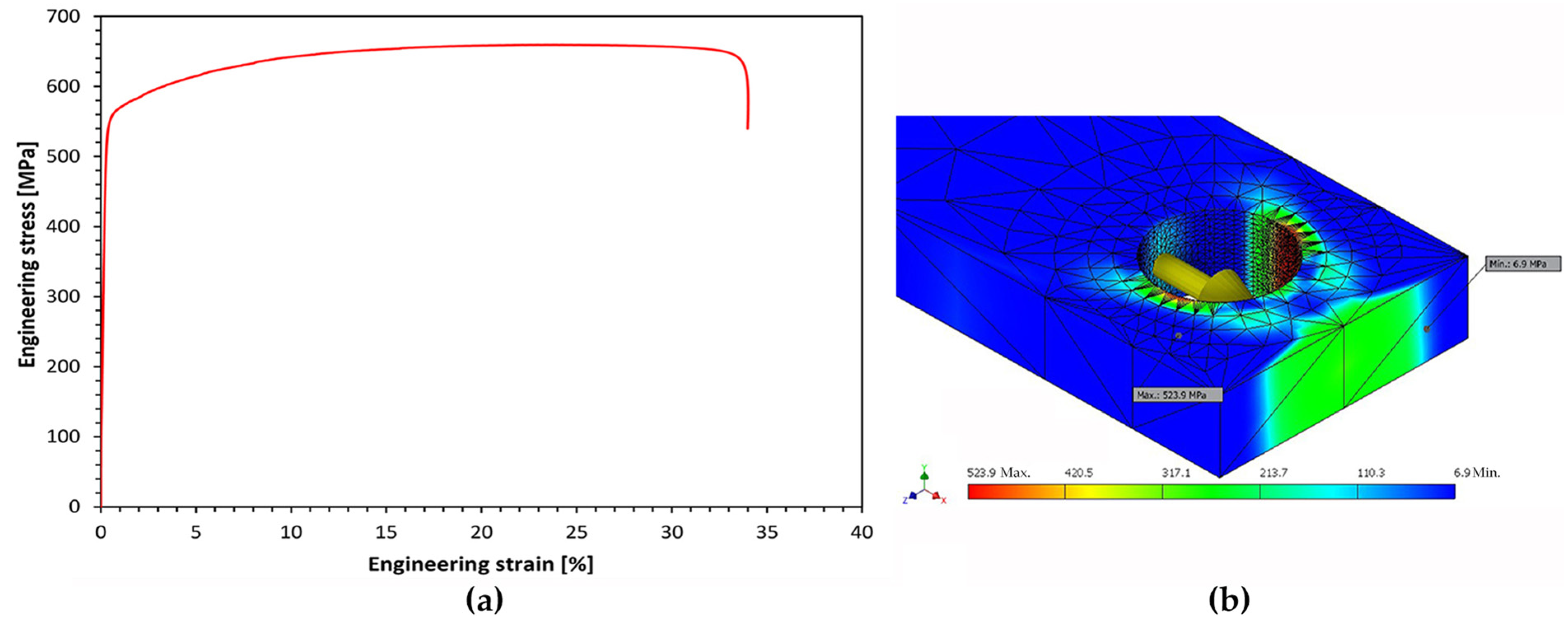
Figure 2a shows the stress-strain behavior of the material, observed during the tensile tests. A yield stress of ~550 MPa is observed, as well as a Young’s modulus of ~191 GPa (evaluated in the range of 150–450 MPa). A preliminary analysis by finite elements showed that the maximum load that can be applied to the samples in a pin-hole configuration, to avoid plastic yielding around the holes in the samples during the HENM tests, is around 5750 N—see Figure 2b. Based on this analysis, the maximum load selected to carry out the HENM tests was 5500 N.
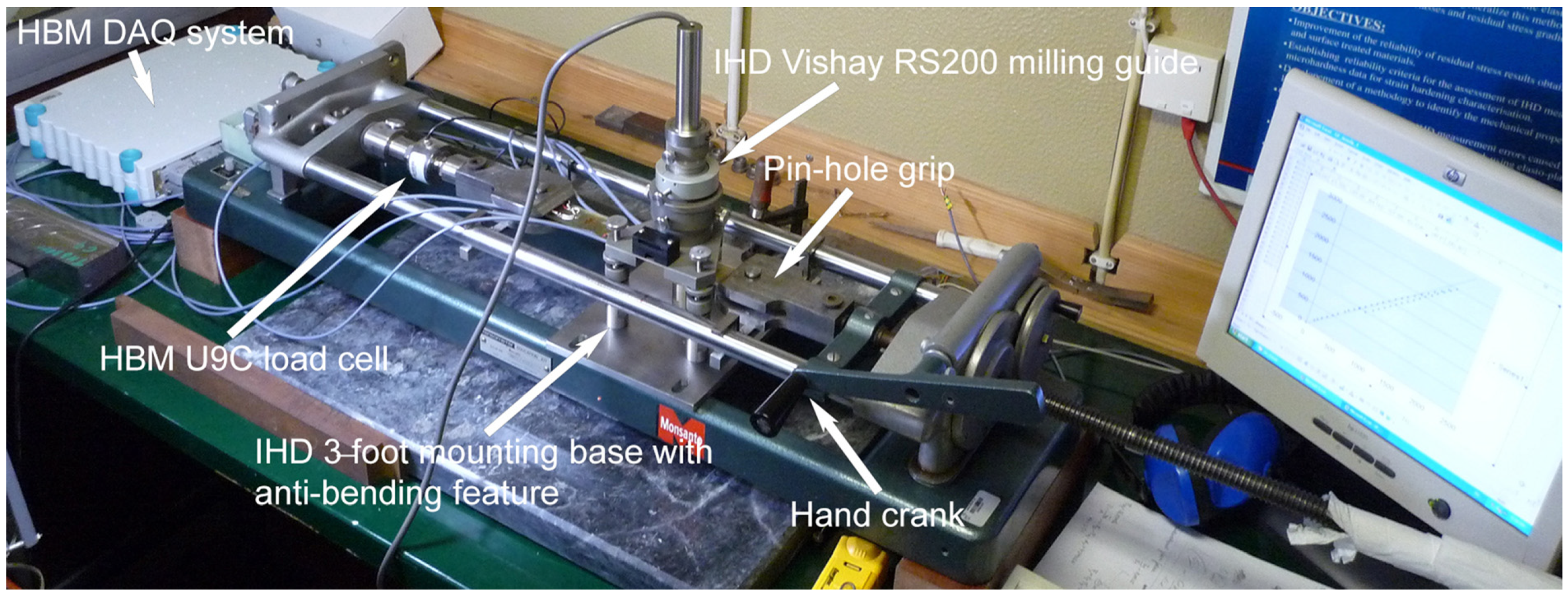
For the minimum load, a load equal to 1000 N was selected. Consequently, a differential load of 4500 N was used in the HENM tests, corresponding to a calibration stress equal to ~56 MPa. The experimental tests were conducted using a manual horizontal tensile test machine, as the experimental setup in Figure 3 shows. The applied load was controlled using an HBM U9C load cell (Hottinger Brüel & Kjær GmbH, Darmstadt, Germany).
Incremental hole-drilling was performed in the tensile samples using an RS200 milling guide system from the Vishay Precision Group, Inc., Malvern, PA, USA. The smallest incremental steps, 20 μm depth, were used for a total of 50 depth increments, corresponding to 1 mm total hole depth and an average final diameter of 1.8 mm. A commercial carbide six-blade inverted cone end mill of 1.6 mm diameter was used and replaced after each test was performed. To decrease to the maximum the heat generation during milling, a very slow touch-and-run approach was followed to perform each incremental depth. Strain measurements were recorded after at least 30 s of waiting time to stabilize the strain signal after milling. Strain and load measurements were done using a Spider 8-30 data acquisition system (Hottinger Brüel & Kjær GmbH, Darmstadt, Germany). This way, experimental strain-depth relaxation curves related to the imposed calibration stress of ~56 MPa could be obtained.
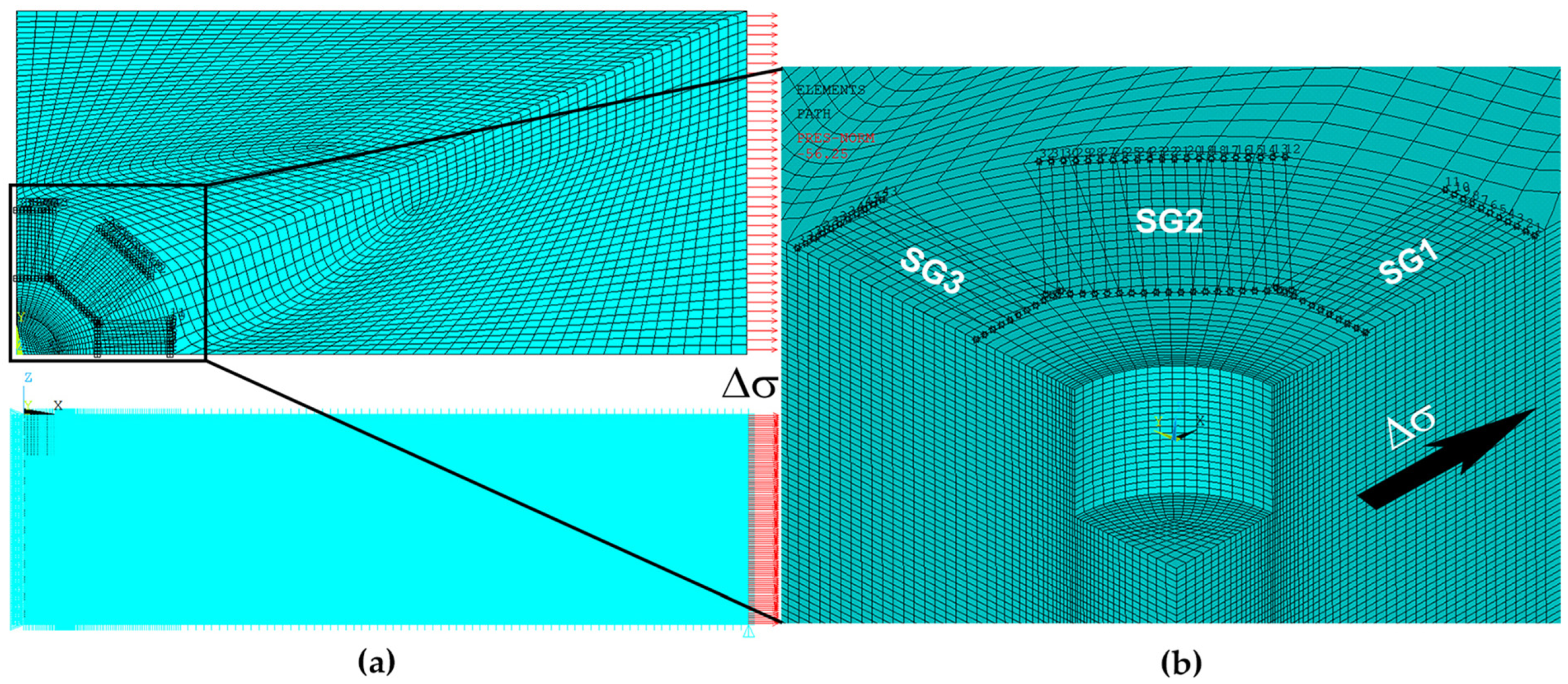
Numerical strain-depth relaxation curves, related to the same calibration stress used in the experimental study, were further obtained by incremental hole simulation using the finite element method. The finite element analysis was performed using the ANSYS 2024 R1 Mechanical APDL code, considering the experimental parameters, i.e., the geometrical parameters of the hole and the geometry of the strain gauge grids of the standard ASTM type A rosette used. Higher-order 3-D SOLID186 20-node isoparametric solid elements, which exhibit quadratic displacement behavior, were considered. Due to symmetry conditions, only 1/4 of the 3D solid model is used, thus substantially reducing calculation time. Figure 4a shows the FEM mesh, the applied stress, and the model constraints. Figure 4b shows the amplified mesh around the hole (mapped mesh). The straight segments represented in Figure 4 (paths) simulate the extensometer grids of the CEA-06-062UL-120 rosettes used in this work. The overlap on the 45° extensometer is apparent, as this extensometer is physically placed in the opposite quadrant. The deformations considered in the numerical simulation are based on integrating their values along the areas corresponding to the strain gauge grids. The incremental hole-drilling is simulated using the “birth and death of elements” ANSYS code features.

5. Experimental Results

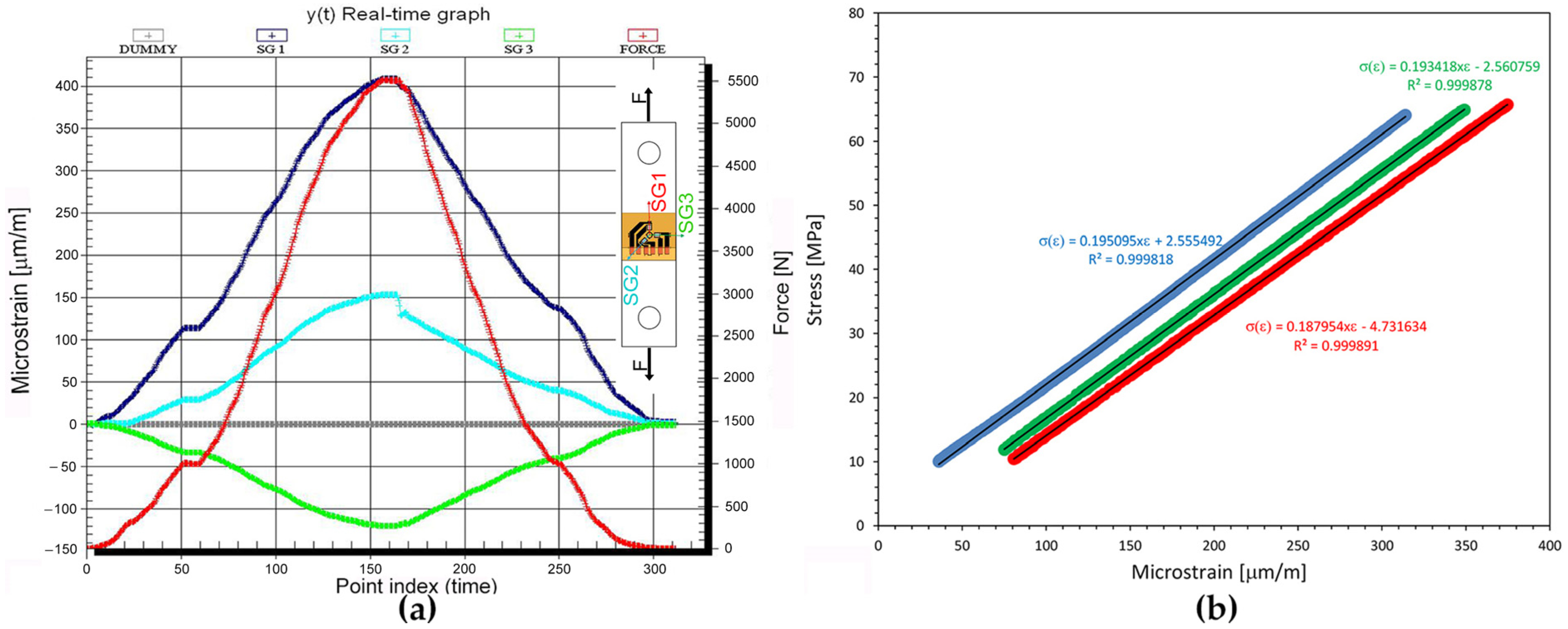
Preliminary tests to verify stress-strain behavior were carried out. The real-time graph in Figure 5a shows, as an example, the load (red line) and strain signals recorded during the loading and unloading of an SLM AISI 316L specimen from 0 to 5500 N (as a function of time). The behavior presented in Figure 5a is observed in all performed tests and samples. Strain gauge 1 (dark blue line-SG1) was aligned with the direction of the applied load, while strain gauge 3 (green line—SG3) was aligned at 90° from the load direction, measuring Poisson’s effect only. Strain gauge 2 (light blue line—SG2) was aligned at 45° from the load direction, presenting a signal between the other two strain gauges. Using the load and the microstrain readings from strain gauge 1, a linear behavior between load and strain is observed, as presented in Figure 5b.
As an example, Figure 6a presents the radial strain reliefs, measured at the surface by the three strain gauges of the ASTM type A standard rosette, as a function of the hole depth, in one of the samples when it is axially loaded at 1000 N and 5500 N, respectively. These values consider the superimposed effect of the applied load and the existing residual stresses. Following the method explained in Section 2 and taking the difference between both cases, it is possible to obtain the strain relaxation as a function of the depth corresponding to the calibration load of 4500 N, as presented in Figure 6b.
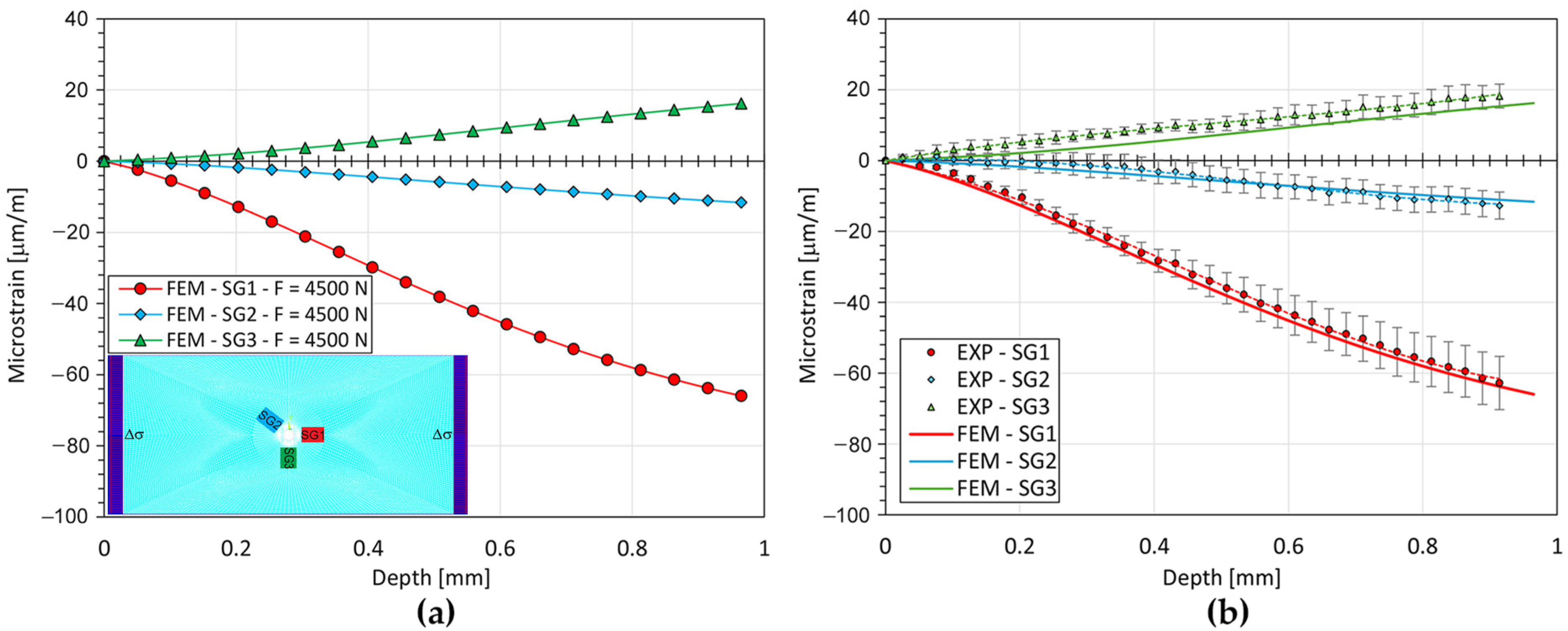
The results presented in Figure 6b are what can be expected when strain relaxation around a hole is measured in a sample subjected to a pure tensile load. Strain gauge 1 (SG1), placed in the direction of the applied load, provides the greatest and most negative strain relaxation values due to the stretching of the sample, while strain gauge 3 (SG3) provides positive strain relaxation values due to the transverse contraction of the sample, i.e., due to Poisson’s effect only. Strain gauge 2 (SG2), placed at 45° from the other two, is expected to provide values in between. These curves can then be used as input data for the unit pulse integral method, briefly explained in Section 3, as shown in the following.

6. Discussion

The incremental hole-drilling can also be numerically simulated, considering the same parameters of the experimental study, as described in the previous Section 4. Figure 7a shows the strain-depth relaxation curve determined by incremental hole simulation using ANSYS, in a modelled sample subjected to a calibration load equal to 4500 N (calibration stress of ~56 MPa). An average hole diameter of 1.8 mm and a standard ASTM type A rosette (CEA-06-062UL-120 from Vishay Precision Group, Inc.) were considered. As expected, the behavior of these curves is like that experimentally determined, shown in Figure 7b, though without the thermomechanical effects of cutting. These curves can be considered ideal curves. It is worth noting that the corresponding stresses are related to the slope of these curves instead of the absolute strain relaxation value at each incremental depth. Considering all the five valid tests performed, the average strain relaxation values taken after each incremental depth, according to the three directions of the standard strain gauge rosette, i.e., load direction (SG1), cross to the load direction (SG3), and at 45° of the load direction (SG2), can be observed in Figure 7b. The uncertainty expressed by the error bars in Figure 7b was determined based on the root mean square error (RMSE) of the tests performed. In general, the uncertainty increases with the increase in hole depth. This is expected since the deeper the hole is, the more difficult and inaccurate the strain measurement at the material’s surface will be. Beyond a certain depth, usually equal to the hole diameter, strain measurement will not be possible anymore due to the lack of sensitivity. For stress calculations using the integral method, the maximum evaluation depth is lower and restricted to a depth equal to the hole radius. After this depth, the method becomes strongly ill-conditioned, and large scattering in the residual stress results is observed. Beyond the sensitivity loss of the strain relaxation corresponding to deeper increments, which is a limitation of IHD itself, care must be taken during the IHD procedure to minimize other possible error sources, such as those related to the strain gauge rosette orientation, the determination of the zero depth at surface, the size of each incremental depth, and the measurement of the final hole diameter. From Figure 7b, a good agreement between the average strain-depth relaxation curves experimentally and numerically determined is observed. The greatest differences appear in the direction transversal to the applied load (SG3). The other two directions are in very good agreement.
From Figure 7b, a good agreement between the average strain-depth relaxation curves experimentally and numerically determined is observed. The greatest differences appear in the direction transversal to the applied load (SG3). The other two directions are in very good agreement.
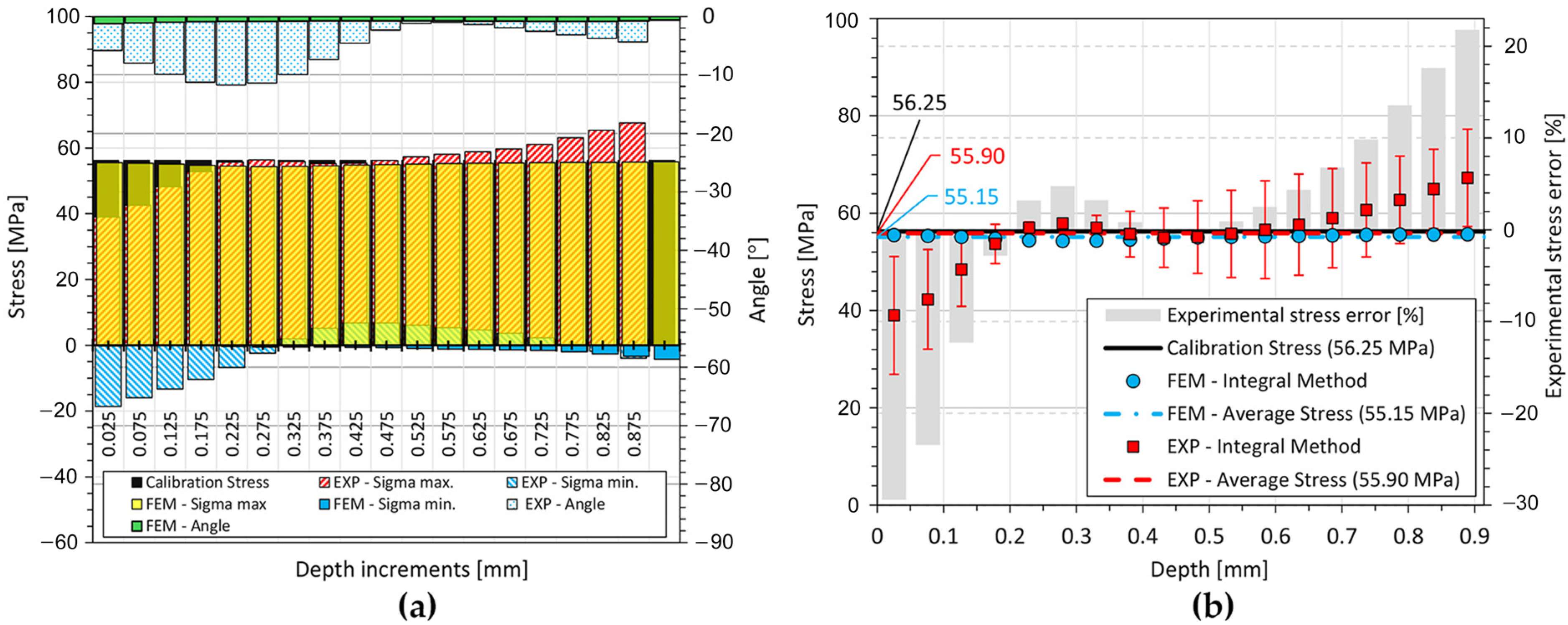
When the curves presented in Figure 7b are used as input for the unit pulse integral method, the corresponding stresses can be obtained. In the present study, a uniaxial stress state is expected, i.e., σ1 = σcal; σ2 = σ3 = 0. Figure 8a presents the principal stresses and the direction of the maximum principal stress related to the direction of strain gauge 1 (SG1), which was oriented with the applied load. The unit pulse integral method only determines the average stress at each incremental depth considered. In Figure 8a, an incremental depth interval of 0.05 mm was considered. The values on the abscissa axis correspond to the mean point at each incremental depth.
The relative error associated with the maximum principal stress determination by IHD simulation by FEM, using the integral method, is below 2%, which is acceptable. The angle between the maximum principal stress and the direction of strain gauge 1, oriented with the load direction, is near zero, as expected, and the value of the minimum principal stress is negligible, only presenting negative values for the deepest hole depth (maximum of ~−4 MPa at the limit evaluation depth). Regarding the experimental results, the maximum principal stress presents lower values than expected near the surface, while the value for the deeper depth increments is greater than expected. However, in between, the experimental results agree well with the expected value (stress calibration value). Minimum principal stress oscillates around zero, varying between −18 MPa and +7 MPa. The angle between the maximum principal stress and the direction of the applied load deviates by a maximum of ~11° at the 5th depth increment. For the sake of clarity, Figure 8b presents a comparison between the calibration stress and the maximum principal stress experimentally and numerically determined.
Data points in Figure 8b correspond to the average stress at each depth increment, referred to as the mean point of each incremental depth. Stress calculation using the unit pulse integral method, based on the strain-depth relaxation curves determined by the incremental hole simulation using ANSYS, agrees very well with the imposed calibration stress. An average value of 55.15 MPa is determined considering the whole hole depth range. It corresponds to an average relative error of 1.95%, which is perfectly acceptable considering the numerical uncertainties and the accuracy of the determination of the calibration coefficients, as per those published by the ASTM E837 standard. On the other hand, as explained before, stress evaluation using the unit pulse integral method based on the strain-depth relaxation curves determined experimentally by incremental hole-drilling, from the experimental tensile tests, presents an error of ~−30% at the first depth increment and around +20% for the last depth increment. The average value obtained in this case is 55.90 MPa. The observed stress errors near the surface and at deeper layers are not expected to occur, considering the strain relaxation results presented in Figure 7b. However, as previously referred, small differences in strain relaxation values can lead to large errors in stress calculation when using the integral method. Considering the observed deviations in the experimental tests performed, which led to the standard deviations on the strain relaxation shown in Figure 7b, it was possible to determine the uncertainty on the stress results, represented by the error bars in Figure 8b.
A close investigation into possible causes for such differences, however, seems to point out a geometrical effect instead of possible thermomechanical effects. In fact, the experimental tests were carried out using commercially available end mills, which usually present chamfers. Figure 9a shows a micrograph of a performed hole, showing the bottom hole chamfer, and Figure 9b shows the end mill used. Figure 9c,d show some issues found on the end mill blades during hole-drilling. The end mills are never reused.
The effect of chamfers was studied by several authors [27,28,29,30,31]. Simon and Gibmeier [29] report an error of ~27% at the first depth increment, when the calibration coefficients are determined considering pure cylindrical shapes with perfectly flat-bottomed increments (the same as those published by the ASTM E837 standard [5]) and used to determine a uniform residual stress, using commercial end mills presenting chamfers. The chamfers affect most of the first depth increments due to smaller material volume removal compared to the case of a purely cylindrical hole. On the other hand, Valentini et al. [38] provide an example of the influence of a hole bottom chamfer on the reconstruction of a pure shear stress distribution. Similarly, with the results found in the present work, the hole bottom chamfer leads to an under-estimation of the actual stress at first depth increments of a magnitude such as that observed by Simon and Gibmeier [39], while at the deepest increments, the results show an over-estimation of the calculated stress, which is also observed in the present work. The effect at deeper layers should now be related to the influence of the error occurring at first depth increments, since according to the integral method, as explained in Section 3, the strain relaxation measured at the material’s surface is the accumulated result of the relieved residual stresses originally existing in the region of each successive increment, along the total hole depth. However, the chamfer’s effect can be corrected if the calibration coefficients are determined by finite element analysis, considering the real hole geometry, as shown in several works [39,40]. Another approach to solving this problem is to avoid the hole bottom chamfer by using orbital drilling with smaller diameter end mills, which is also beneficial regarding the thermomechanical effects of the cutting procedure. Overall, the incremental hole-drilling technique seems to be able to accurately determine residual stresses in additively manufactured AISI 316L.

7. Conclusions

The hybrid experimental-numerical method used in this work is an effective method to verify the ability of the incremental hole-drilling technique (IHD) to measure residual stresses in materials.
Experimentally determined strain-depth relaxation curves, related to an imposed calibration stress in the tensile tests, agree well with those numerically simulated. These curves, used as input for the unit pulse integral method for IHD residual stress calculation, led to the determination of the stress existing at each depth increment. This inverse method is very sensitive to measurement errors. Thus, while the stress determined using the numerically simulated curves is almost uniform over the total hole depth and within 2% of the expected calibration stress, the stress determined using the experimentally obtained curves presents differences, particularly at first depth increments and deeper depth increments.
Despite the observed differences in the experimentally evaluated stress, which seem to be related to the hole bottom chamfer effect and, therefore, can be corrected, the results show that the incremental hole-drilling technique, using the standard ASTM E837 procedure, is a suitable technique for measuring residual stresses in the austenitic steel AISI 316L manufactured by selective laser melting. Smallest possible depth increments, low feed rates, and adequate waiting times (at least 30 s), using commercially available equipment and end mills, can lead to acceptable results. However, for greater measurement accuracy, the effect of chamfers should be avoided by using small-diameter end mills in orbital drilling procedures. Orbital drilling can also reduce the thermomechanical effects of the cutting procedure and, therefore, whenever possible, should be the selected drilling procedure.

Author Contributions

Conceptualization, J.P.N. and M.J.M.; methodology, J.P.N.; software and FEM, J.P.N.; validation, J.P.N. and M.J.M.; formal analysis, J.P.N. and M.J.M.; investigation, J.P.N., M.J.M. and A.C.B.; resources, A.C.B.; writing—original draft preparation, J.P.N.; writing—review and editing, J.P.N., M.J.M. and A.C.B.; project administration, J.P.N. and A.C.B.; funding acquisition, J.P.N., M.J.M. and A.C.B. All authors have read and agreed to the published version of the manuscript.

Funding

This work was financed through national funds by FCT—Fundação para a Ciência e Tecnologia, I.P. in the framework of the projects UIDB/04564/2020 and UIDP/04564/2020, with DOI identifiers 10.54499/UIDB/04564/2020 and 10.54499/UIDP/04564/2020, respectively.

Data Availability Statement

The raw data supporting the conclusions of this article will be made available by the authors on request.

Acknowledgments

Abílio de Jesus, from the Department of Mechanical Engineering at the University of Porto, and Tiago Silva, from INEGI, are thanked for the SLM-manufactured material and the preparation of the samples.

Conflicts of Interest

The authors declare no conflict of interest.

References

  1. Sefene, E.M. State-of-the-art of selective laser melting process: A comprehensive review. J. Manuf. Syst. 2022, 63, 250–274. [Google Scholar] [CrossRef]
  2. Mansoura, A.; Omidi, N.; Barka, N.; Karganroudi, S.S.; Dehghan, S. Selective Laser Melting of Stainless Steels: A review of Process, Microstructure and Properties. Met. Mat. Int. 2024, 30, 2343–2371. [Google Scholar] [CrossRef]
  3. Salmi, A.; Atzeni, E.; Iuliano, L.; Galati, M. Experimental Analysis of Residual Stresses on AlSi10Mg Parts Produced by Means of Selective Laser Melting (SLM). Procedia CIRP 2017, 62, 458–463. [Google Scholar] [CrossRef]
  4. Liu, Y.; Yang, Y.; Wang, D. A study on the residual stress during selective laser melting (SLM) of metallic powder. Int. J. Adv. Manuf. Technol. 2016, 87, 647–656. [Google Scholar] [CrossRef]
  5. ASTM-E837-20; Standard Test Method for Determining Residual Stresses by the Hole-Drilling Strain-Gage Method. ASTM International: West Conshohocken, PA, USA, 2020.
  6. Schajer, G.S.; Whitehead, P.S. Hole-Drilling Method for Measuring Residual Stresses; Springer: Cham, Switzerland, 2018; pp. 1–172. [Google Scholar] [CrossRef]
  7. Barsanti, M.; Beghini, M.; Santus, C.; Benincasa, A.; Bertelli, L. Integral method coefficients for the ring-core technique to evaluate non-uniform residual stresses. J. Strain Anal. Eng. Des. 2018, 53, 210–224. [Google Scholar] [CrossRef]
  8. Leggatt, R.H.; Smith, D.J.; Smith, S.D.; Faure, F. Development and experimental validation of the deep hole method for residual stress measurement. J. Strain Anal. Eng. Des. 1996, 31, 177–186. [Google Scholar] [CrossRef]
  9. Hill, M.R. The Slitting Method. In Practical Residual Stress Measurement Methods; Schajer, G.S., Ed.; Wiley: Hoboken, NJ, USA, 2013; pp. 89–108. [Google Scholar] [CrossRef]
  10. Prime, M.B.; DeWald, A.T. The Contour Method. In Practical Residual Stress Measurement Methods; Schajer, G.S., Ed.; Wiley: Hoboken, NJ, USA, 2013; pp. 109–138. [Google Scholar] [CrossRef]
  11. Hauk, V. Structural and Residual Stress Analysis by Nondestructive Methods; Elsevier Science B.V.: Amsterdam, The Netherlands, 1997. [Google Scholar] [CrossRef]
  12. Santa-aho, S.; Kiviluoma, M.; Jokiaho, T.; Gundgire, T.; Honkanen, M.; Lindgren, M.; Vippola, M. Additive Manufactured 316L Stainless-Steel Samples: Microstructure, Residual Stress and Corrosion Characteristics after Post-Processing. Metals 2021, 11, 182. [Google Scholar] [CrossRef]
  13. Geľatko, M.; Hatala, M.; Botko, F.; Vandžura, R. Residual Stress Evaluation in L-PBF-Produced SS 316L Specimens. Materials 2024, 17, 2270. [Google Scholar] [CrossRef]
  14. Yadroitsev, I.; Yadroitsava, I. Evaluation of residual stress in stainless steel 316L and Ti6Al4V samples produced by selective laser melting. Virtual Phys. Prototyp. 2015, 10, 67–76. [Google Scholar] [CrossRef]
  15. Cheng, M.; Zou, X.; Chang, T.; Cao, Q.; Ju, H.; Luo, G.; Zou, Z.; Wu, Z. Residual Stresses of 316L Stainless Steel Laser Direct Metal During Pulsed-Wave and Continuous-Wave Laser Additive Manufacturing: A Comparative Study. Coatings 2024, 14, 1598. [Google Scholar] [CrossRef]
  16. Chen, W.; Voisin, T.; Zhang, Y.; Forien, J.-B.; Spadaccini, C.M.; McDowell, D.L.; Zhu, T.; Wang, Y.M. Microscale residual stresses in additively manufactured stainless steel. Nat. Commun. 2019, 10, 4338. [Google Scholar] [CrossRef] [PubMed]
  17. Simson, T.; Emmel, A.; Dwars, A.; Böhm, J. Residual stress measurements on AISI 316L samples manufactured by selective laser melting. Addit. Manuf. 2017, 17, 183–189. [Google Scholar] [CrossRef]
  18. Beltrami, M.; Pelegatti, M.; Magnan, M.; Lanzutti, A.; Avdeev, M.; Luzin, V.; Leoni, M.; De Bona, F.; Salvati, E. Microstructure and residual stress evolution during cyclic elastoplastic deformation of AISI316L fabricated via laser powder bed fusion. Mater. Sci. Eng. A 2024, 898, 146416. [Google Scholar] [CrossRef]
  19. Piscopo, G.; Salmi, A.; Atzeni, E. Influence of High-Productivity Process Parameters on the Surface Quality and Residual Stress State of AISI 316L Components Produced by Directed Energy Deposition. J. Mater. Eng. Perform. 2021, 30, 6691–6702. [Google Scholar] [CrossRef]
  20. Gu, J.; Li, R.; Qiu, Y.; Yue, H.; Liu, B.; Gu, H. Microstructure, Mechanical Properties, and Residual Stress Distribution of AISI 316L Stainless Steel Part Fabricated by Laser Metal Deposition. Scanning 2020, 4831798. [Google Scholar] [CrossRef]
  21. D’Andrea, D. Additive Manufacturing of AISI 316L Stainless Steel: A Review. Metals 2023, 13, 1370. [Google Scholar] [CrossRef]
  22. Schajer, G.S. Measurement of Non-Uniform Residual Stress Using the Hole-Drilling Method. Part II-Practical Application of The Integral Method. J. Eng. Mater. Technol. 1988, 110, 344–349. [Google Scholar] [CrossRef]
  23. Schajer, G.S. Hole-Drilling Residual Stress Profiling with Automated Smoothing. J. Eng. Mater. Technol. 2007, 129, 440–445. [Google Scholar] [CrossRef]
  24. Nobre, J.P.; Kornmeier, M.; Scholtes, B. Plasticity Effects in the Hole-Drilling Residual Stress Measurement in Peened Surfaces. Exp. Mech. 2018, 58, 369–380. [Google Scholar] [CrossRef]
  25. Shokrani, A.; Dhokia, V.; Newman, S.T. Environmentally conscious machining of difficult-to-machine materials with regard to cutting fluids. Int. J. Mach. Tools Manuf. 2012, 57, 83–101. [Google Scholar] [CrossRef]
  26. Flaman, M.T. Brief investigation of induced drilling stresses in the center-hole method of residual-stress measurement. Exp. Mech. 1982, 22, 26–30. [Google Scholar] [CrossRef]
  27. Flaman, M.T.; Herring, J.A. Comparison of Four Hole-Producing Techniques for the Center-Hole Residual-Stress Measurement Method. Exp. Tech. 1985, 9, 30–32. [Google Scholar] [CrossRef]
  28. Schajer, G.S.; Altus, E. Stress Calculation Error Analysis for Incremental Hole-Drilling Residual Stress Measurements. J. Eng. Mater. Technol. 1996, 118, 120–126. [Google Scholar] [CrossRef]
  29. Weng, C.C.; Lin, Y.C.; Chou, C.P. A new approach for determining the induced drilling stresses in the hole-drilling method of residual-stress measurement. Exp. Tech. 1992, 16, 33–35. [Google Scholar] [CrossRef]
  30. Lee, H.T.; Liu, C.; Hsu, F.C.; Hsu, J.M. An Enhanced Calibration Scheme for the EDM Hole-Drilling Strain Gage Method for the Measurement of Residual Stress in Ferrous Materials. Mater. Trans. 2008, 49, 1905–1910. [Google Scholar] [CrossRef]
  31. Simmons, J.C.; Chen, X.; Azizi, A.; Daeumer, M.A.; Zavalij, P.Y.; Zhou, G.; Schiffres, S.N. Influence of processing and microstructure on the local and bulk thermal conductivity of selective laser melted 316L stainless steel. Addit. Manuf. 2020, 32, 100996. [Google Scholar] [CrossRef]
  32. Nobre, J.P.; Stiffel, J.H.; Paepegem, W.V.; Nau, A.; Batista, A.C.; Marques, M.J.; Scholtes, B. Quantifying the Drilling Effect during the Application of Incremental Hole-Drilling Technique in Laminate Composites. Mater. Sci. Forum. 2011, 681, 510–515. [Google Scholar] [CrossRef]
  33. Nobre, J.P.; Smit, T.C.; Reid, R.; Qhola, Q.; Wu, T.; Niendorf, T. Stress Evaluation Through the Layers of a Fibre-Metal Hybrid Composite by IHD: An Experimental Study. Exp. Mech. 2024, 64, 487–500. [Google Scholar] [CrossRef]
  34. Schajer, G.S. Measurement of Non-Uniform Residual Stress Using the Hole-Drilling Method. Part I—Stress Calculation Procedures. J. Eng. Mater. Technol. 1988, 110, 338–343. [Google Scholar] [CrossRef]
  35. Schajer, G.; Prime, M. Use of Inverse Solutions for Residual Stress Measurement. J. Eng. Mater. Technol. 2006, 128, 375–382. [Google Scholar] [CrossRef]
  36. Schajer, G.S. Application of Finite Element Calculations to Residual Stress Measurements. J. Eng. Mater. Technol. 1981, 103, 157–163. [Google Scholar] [CrossRef]
  37. Zuccarello, B. Optimal calculation steps for the evaluation of residual stress by the incremental hole-drilling method. Exp. Mech. 1999, 39, 117–124. [Google Scholar] [CrossRef]
  38. Valentini, E.; Bertelli, L.; Benincasa, A.; Gulisano, S. Recent Advancements in the Hole-Drilling Strain-Gage Method for Determining Residual Stresses. In New Challenges in Residual Stress Measurements and Evaluation; Casavola, C., Barile, C., Moramarco, V., Pappalettera, G., Eds.; IntechOpen: Rijeka, Croatia, 2019; Chapter 4. [Google Scholar] [CrossRef]
  39. Simon, N.; Gibmeier, J. Consideration of Tool Chamfer for Realistic Application of the Incremental Hole-Drilling Method. Mater. Res. Proc. 2017, 2, 473–478. [Google Scholar] [CrossRef]
  40. Blödorn, R.; Bonomo, L.A.; Viotti, M.R.; Schroeter, R.B.; Albertazzi, A. Calibration Coefficients Determination Through Fem Simulations for the Hole-Drilling Method Considering the Real Hole Geometry. Exp. Tech. 2017, 41, 37–44. [Google Scholar] [CrossRef]
Figure 1. (a) AISI 316L specimens for (a) tensile tests and (b) the HENM method.
Metals 15 00485 g001
Figure 2. (a) Stress-strain behavior of AISI 316L specimens obtained by SLM. (b) von Mises stress distribution around the holes, obtained by FE analysis, when a load of 5750 N is applied through the pins during the HENM tests.
Metals 15 00485 g002
Figure 3. Experimental setup, showing the horizontal tensile test machine used, the IHD milling machine, and the data acquisition system (DAQ).
Metals 15 00485 g003
Figure 4. (a) FEM mesh and constraints (top and front view). (b) Mesh amplification near the 1.8 mm diameter hole showing the paths which represent the strain gauge grids (1 mm depth).
Metals 15 00485 g004
Figure 5. (a) Real-time data of force and strain. (b) Stress-strain behavior observed in three tensile tests.
Metals 15 00485 g005
Figure 6. Strain relaxation vs. hole depth obtained in a sample. (a) Net results for 1000 N and 5500 N axial loads. (b) Corresponding results for the 4500 N differential load.
Metals 15 00485 g006
Figure 7. (a) Strain-depth relaxation curves numerically simulated using ANSYS for a calibration stress of ~56 MPa, 1.8 mm hole diameter, and standard ASTM type A rosette (CEA-06-062UL-120 from Vishay Precision Group, Inc.). (b) Experimental and numerical strain-depth relaxation curves comparison.
Metals 15 00485 g007
Figure 8. (a) Experimental and numerical maximum and minimum principal stresses and their orientation at each incremental depth. (b) Calibration stress vs. experimentally and numerically determined values.
Metals 15 00485 g008
Figure 9. (a) Hole bottom chamfer (red circles), (b) inverted cone end mill used, (c) blade damage (material removed), and (d) signs of material transfer (adhesion) on blade.
Metals 15 00485 g009
Table 1. Chemical composition of austenitic stainless-steel powders AISI 316L.
ElementCCrNMnMoNiPSSiOFe
Weight (%)<0.0316–18<0.10<22–310–14<0.045<0.03<1<0.1bal
Table 2. SLM process parameters.
Laser PowerLayer ThicknessScan SpeedParticle ∅Distance Between Paths
300 W50 μm1 ms−115–45 μm110 μm
Disclaimer/Publisher’s Note: The statements, opinions and data contained in all publications are solely those of the individual author(s) and contributor(s) and not of MDPI and/or the editor(s). MDPI and/or the editor(s) disclaim responsibility for any injury to people or property resulting from any ideas, methods, instructions or products referred to in the content.