Article

Research on Microstructure and Mechanical Properties of Ultrasonic-Assisted Gas Metal Arc Welding Additive Manufacturing with High-Nitrogen Steel Welding Wire

State Key Laboratory of Precision Welding & Joining of Materials and Structures, Harbin Institute of Technology, Harbin 150001, China
*
Author to whom correspondence should be addressed.
Metals 2025, 15(5), 491; https://doi.org/10.3390/met15050491 (registering DOI)
Submission received: 14 March 2025 / Revised: 15 April 2025 / Accepted: 24 April 2025 / Published: 27 April 2025

Abstract

:
High-nitrogen steels (HNSs) are valued for their superior mechanical strength and corrosion resistance, making them ideal for high-end industrial applications. However, nitrogen loss during gas metal arc welding additive manufacturing (GMAW-AM) often results in porosity and coarse microstructures, degrading component performance. This study introduces a coaxial ultrasonic-assisted GMAW-AM (U-GMAW-AM) process to mitigate nitrogen loss and refine the microstructure. Welding wires with 0.35 wt.% and 0.70 wt.% nitrogen were used to examine the effects of welding voltage (24.5–30 V) and ultrasonic power (0–2 kW). The results show that a higher voltage increases nitrogen evaporation, with a maximum loss of 0.22% at 30 V. In contrast, ultrasonic assistance reduces nitrogen loss by up to 29.17% for the 0.70 wt.% wire. Microstructural analysis reveals a significant reduction in ferrite and enhanced austenite formation due to better nitrogen retention. Mechanical testing shows that ultrasonic assistance improves tensile strength by 100 MPa (up to 919.1 MPa), elongation by nearly 10%, and hardness uniformity. These findings highlight the potential of ultrasonic assistance for optimizing high-nitrogen steel properties in additive manufacturing.

1. Introduction

High-nitrogen steels (HNSs) are characterized by nitrogen content exceeding 0.08 wt.% in ferritic/martensitic stainless steels or surpassing 0.4 wt.% in austenitic stainless steels. These steels promote the formation and stability of austenite phases while suppressing ferrite formation. Recent advancements in high-nitrogen steels have significantly enhanced their mechanical and functional properties, driven by innovations in pressurized melting and alloy design. These enhanced properties like superior strength, toughness, and corrosion resistance make HNS ideal for applications in naval engineering, transportation infrastructure, chemical processing, automotive/aerospace industries, the nuclear sector, and defense [1,2,3,4].
Wire arc additive manufacturing (WAAM) is a promising technique that uses an electric arc as a heat source to melt and deposit consumable wire electrode material layer by layer. The heat sources commonly employed in WAAM include gas tungsten arc (GTA) [5], gas metal arc (GMA) [6], cold metal transfer (CMT) [7,8], and plasma arc welding (PAW) [9]. Gas metal arc welding additive manufacturing (GMAW-AM) combines traditional GMAW with WAAM, which offers several advantages, including high deposition efficiency, material versatility, and cost-effectiveness, making it suitable for manufacturing, repairing, and customizing large, complex metal components [10,11].
During the high-temperature process involved in WAAM, nitrogen atoms can aggregate to form molecular nitrogen (N2), leading to nitrogen evaporation during molten droplet transfer. This results in spattering, nitrogen loss, and undesirable formation of ferrite phases, negatively affecting mechanical properties. Additionally, nitrogen gas entrapment within the weld pool generates porosity defects, further compromising component performance [12,13,14,15,16]. Therefore, mitigating nitrogen loss in nitrogen-containing welding wire during the molten droplet transfer process and minimizing nitrogen gas-induced porosity have become critical challenges in additive manufacturing and welding processes that utilizing nitrogen-enriched wires, thereby demanding the implementation of advanced process control strategies to ensure component reliability.
Existing approaches have addressed nitrogen loss in high-nitrogen steel welding and additive manufacturing by optimizing shielding gases [17,18,19,20,21], adjusting wire compositions [22,23,24], adding nitride additions [25,26,27,28], and improving welding parameters [29,30]. For example, incorporating 5% nitrogen into the shielding gas environment enhances austenite stability, refines microstructure, and improves corrosion resistance in 2205 duplex stainless-steel welds [17]. Hosseini [22] proposed nitrogen-rich filler metals for microstructure control. Cheng et al. [26] found that ambient-pressure laser powder bed fusion fabricates high-nitrogen austenitic steel via rapid solidification, achieving full austenite. However, current solutions have not fully addressed the issue of nitrogen evaporation during dynamic droplet transfer processes, particularly in GMAW-based additive manufacturing, where nitrogen bubble formation and expansion remain unresolved challenges.
To address this limitation, the present study introduces ultrasonic-assisted GMAW (U-GMAW)—a novel approach that integrates high-frequency acoustic energy into the arc welding processes. Ultrasonic-assisted welding employs high-frequency vibrations to enhance arc stability, improve molten droplet transfer, and increase weld penetration. In ultrasonic-assisted gas tungsten arc welding (U-GTAW), ultrasonic energy has been shown to improve joint quality and mitigate shallow penetration in thick plates [31]. For ultrasonic-assisted gas metal arc welding (U-GMAW), coaxial ultrasonic vibrations generate acoustic radiation forces that refine droplet size, increase transfer frequency, and stabilize the arc [32,33]. Preliminary studies on ultrasonic-assisted GMAW using high-nitrogen steel welding wire have demonstrated that ultrasonic energy reduces nitrogen loss in metal transfer process by suppressing nitrogen bubble formation and expansion [34]. The coaxial ultrasonic-assisted technique is distinguished from conventional methods by its ability to actively regulate nitrogen behavior during droplet transfer—a critical phase that remains inadequately addressed in traditional additive manufacturing. Building on these findings, this study further investigates the effects of ultrasonic assistance on the microstructure, nitrogen retention, and mechanical properties of GMAW-AM components fabricated with high-nitrogen steel wire, thereby advancing the understanding of process–microstructure–performance relationships in ultrasonic-enhanced additive manufacturing systems.

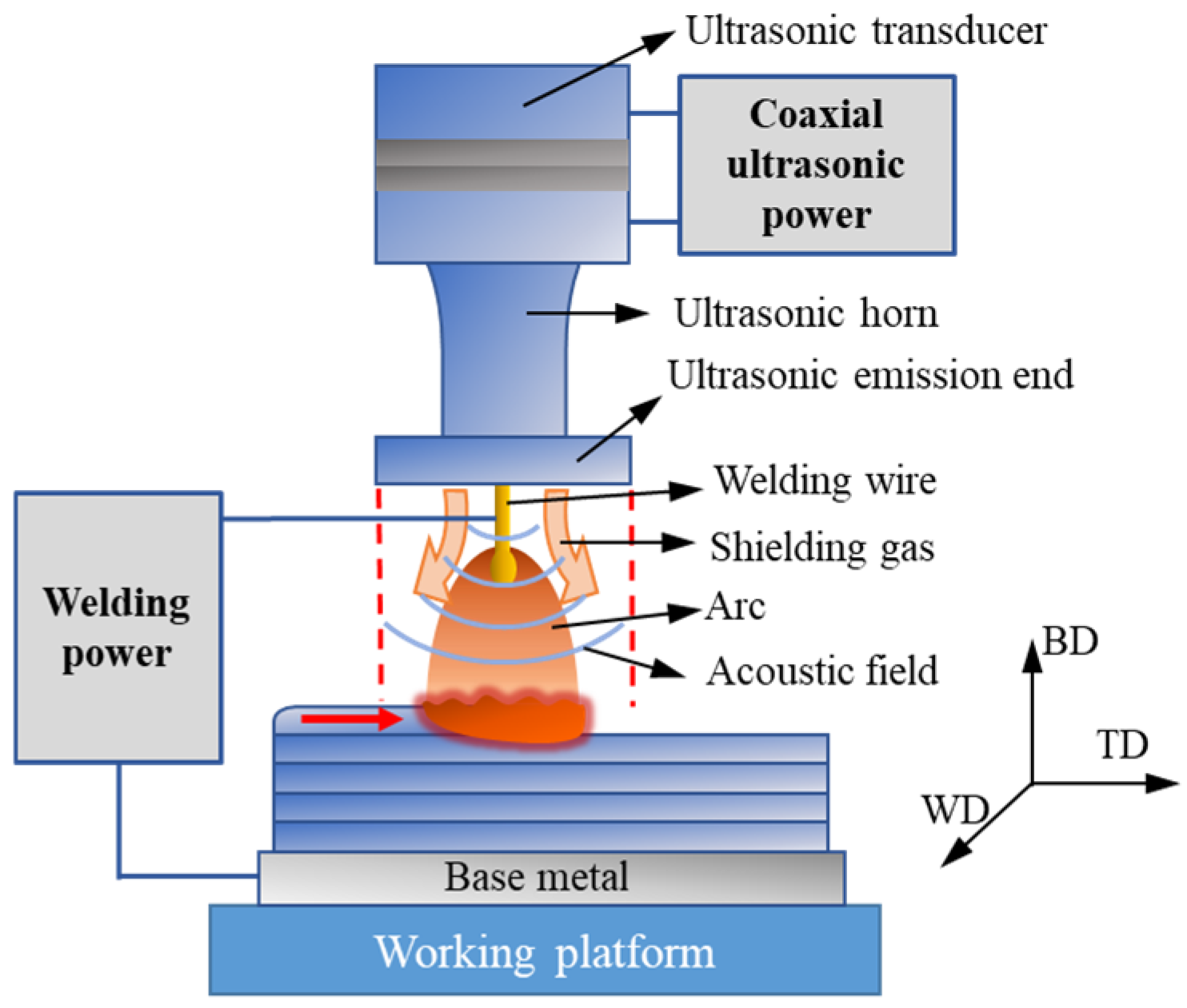
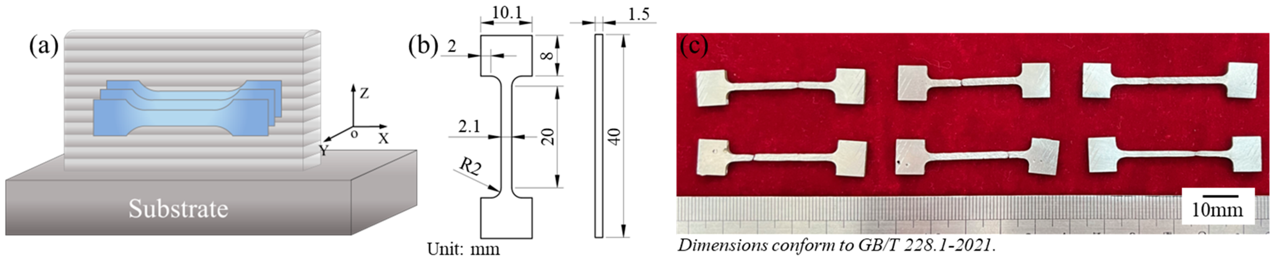
2. Materials and Methods

A schematic diagram of the ultrasonic-assisted GMAW-AM (U-GMAW-AM) setup is shown in Figure 1. The ultrasonic transducer was coaxially integrated with the welding wire, transmitting ultrasonic force downward. The ultrasonic frequency used was 20 kHz. The intensity of the ultrasonic energy field and the resulting acoustic radiation are closely related to the position of the ultrasonic emitter. Changes in the height of the integrated ultrasonic torch system significantly influenced the welding voltage. As such, ultrasonic power, ultrasonic emission height, and welding voltage were identified as key process parameters affecting additive manufacturing performance.
A CLOOS QinTron welding machine (CLOOS, Haiger, Germany) was employed. The shielding gas comprised 98% Ar and 2% O2, delivered at a flow rate of 20 L/min. During the additive manufacturing process, the primary orientation axes included the travel direction (TD), build direction (BD, or deposition height), and width direction (WD) of the component. The substrate material was 304 stainless steel (130 mm × 50 mm × 7 mm), and the welding wires had nitrogen contents of 0.35 wt.% and 0.70 wt.%, respectively (Table 1).
During short-circuit transfer, the ultrasonic emission height was set at the first resonant height (H1), where the ultrasonic effect was most pronounced. Based on a preliminary experiment, H1 was determined to be 14 mm. For globular transfer mode—characterized by a higher arc voltage and longer arc length—the emitter was set at the second resonant height (H2), measured as 20 mm [34].
Parameter optimization experiments identified stable metal transfer conditions for each level of nitrogen content, following a previous study. For the 0.35 wt.% N wire, short-circuit transfer was achieved at a wire feed speed (WFS) of 6 m/min and 24.5 V, while globular transfer occurred at 30 V. For the 0.70 wt.% N wire, stable transfer modes were observed at a WFS of 7 m/min (24.5 V) and 7.5 m/min (28 V and 30 V). To preliminarily evaluate the effect of coaxial ultrasound on single-layer deposition morphology, cross-sectional profiles of the 0.70 wt.% N specimens were compared with and without ultrasonic assistance under three voltage conditions. Detailed process parameters are listed in Table 2. The travel speed (TS) was maintained at 360 mm/min.
Cross-sectional specimens of additively manufactured components were prepared for metallographic analysis. The specimens were polished using sandpapers (240# to 3000# grit) and diamond suspensions (3 μm, 1 μm, and 40 nm particle sizes), followed by electrochemical etching in a 10% oxalic acid solution. Microstructural analysis was conducted using optical microscopy (OLYMPUS SZX12 and VHX-1000; Olympus Corporation, Tokyo, Japan) and scanning electron microscopy (SEM; Hitachi SU 5000, Hitachi High-Tech Corporation, Tokyo, Japan). Elemental composition was analyzed using energy-dispersive spectroscopy (EDS) integrated with SEM.
Five tensile specimens were extracted from the same position in each AM component, oriented parallel to the deposition direction and dimensioned as shown in Figure 2 [35]. Tensile testing was performed using a Shimadzu AGXplus 250 kN tensile testing machine (Shimadzu Corporation, Kyoto, Japan) at a loading rate of 1 mm/min. Microhardness measurements were conducted using an HVS-1000 Vickers microhardness tester (Shanghai Optical Instruments Co., Ltd., Shanghai, China) with a 200 g load applied for a dwell time of 10 s.
The nitrogen content of AM components was quantified using an ONH836 analyzer (Leco Corporation, St. Joseph, MI, USA), as shown in Figure 3a, mainly used for oxygen, nitrogen, and hydrogen quantification in inorganic substrates, including metals, alloys, and ceramics. Sampling locations and specimen geometries are detailed in Figure 3b, with the analyzed regions located near the 10th deposition layer, corresponding to a build height of approximately 10 mm.

3. Results

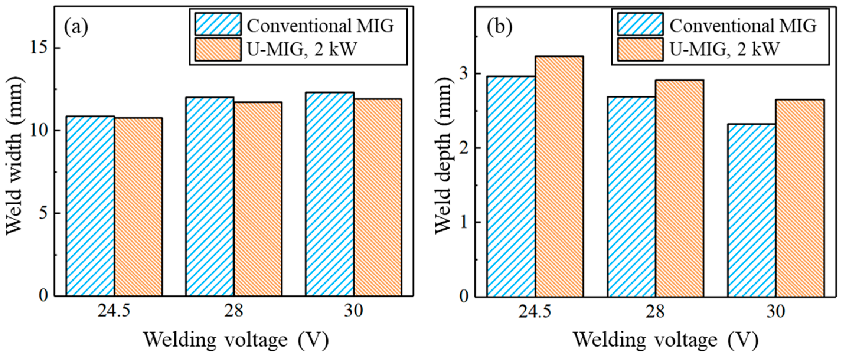
3.1. Geometric Dimensions of Single-Layer U-GMAW-AM

The weld bead formation patterns were similar for both types of welding wire. Figure 4 displays the cross-sectional morphology of deposition beads produced with and without ultrasonic treatment at three welding voltages for the 0.70 wt.% nitrogen wire. The localized porosity observed in Figure 4d is attributed to intensified molten pool dynamics in the first layer of deposition with ultrasonic assistance, which was not observed in other layers. The statistical results of weld width and depth, shown in Figure 5, indicate the following trends: with increasing welding voltage, the bead width increased proportionally, while the bead depth decreased accordingly. Although ultrasonic treatment resulted in a slight reduction in bead width across all tested voltages, the difference was not statistically significant. In contrast, a discernible increase in bead depth was observed under ultrasonic conditions. This enhancement in depth is beneficial for improving interlayer fusion during additive manufacturing processes.

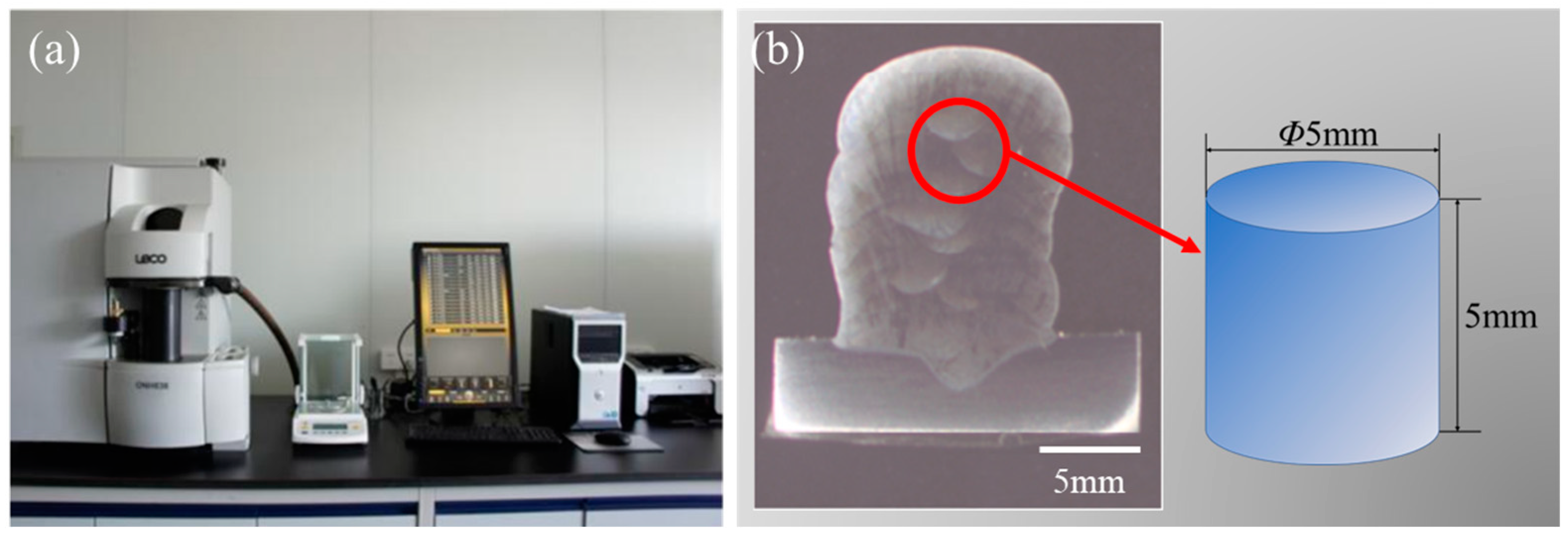
3.2. Nitrogen Pores of Conventional and U-GMAW-AM

Based on the parameters of the single-layer deposition experiment, multi-layer conventional and U-GMAW-AM were conducted on 0.35 wt.% and 0.70 wt.% nitrogen wires at three welding voltages (24.5 V, 28 V, and 30 V) with 15~20 layers of deposition and a deposition height of approximately 15 mm. The cross-sectional morphology of the AM components was analyzed to evaluate forming quality and porosity defects. As shown in Figure 6a, the 0.35 wt.% nitrogen wire exhibited good forming quality in both conventional and U-GMAW-AM processes, with no detectable macroscopic pores. However, for the 0.70 wt.% nitrogen wire, at 24.5 V (short-circuit transfer mode), conventional GMAW produced well-formed deposits with negligible porosity, whereas ultrasonic assistance led to a significant increase in macroscopic pore formation. At 30 V (globular transfer mode), conventional GMAW-AM resulted in minor porosity, while no macroscopic pores were found under ultrasonic assistance.

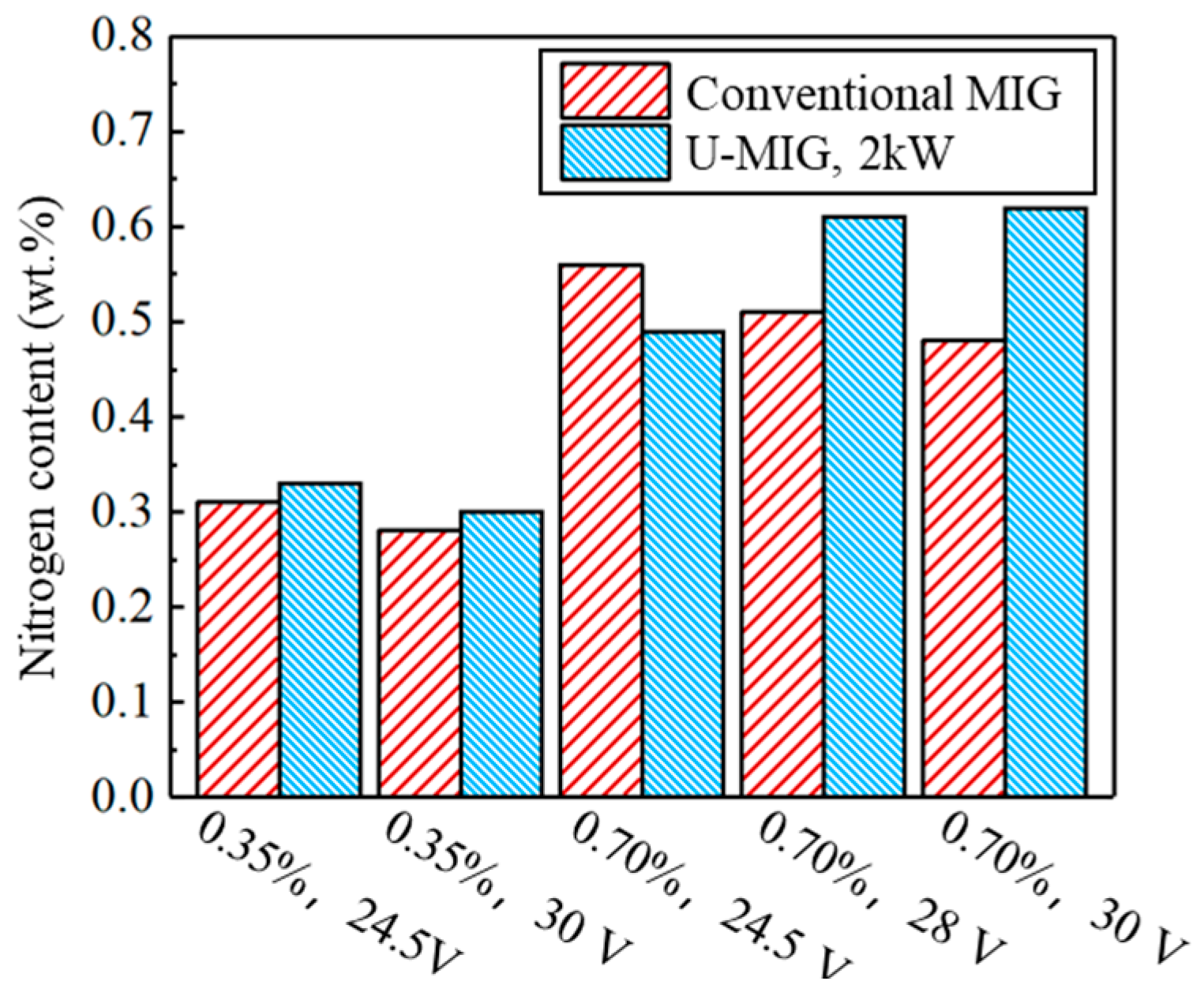
3.3. Nitrogen Content of Conventional and U-GMAW-AM

The nitrogen content of the AM components was analyzed using an oxygen–nitrogen–hydrogen analyzer, with the results summarized in Table 3.
For the 0.35 wt.% nitrogen wire under conventional GMAW-AM, nitrogen losses of 0.04% and 0.07% were observed at 24.5 V (short-circuit transfer) and 30 V (globular transfer), respectively. Ultrasonic assistance increased the nitrogen content by 0.02% in both cases, corresponding to growth rates of 6.45% (24.5 V) and 7.14% (30 V). The relatively modest improvements can be attributed to the low initial nitrogen concentration of the wire and inevitable nitrogen losses under atmospheric conditions. Nevertheless, ultrasonic treatment enhanced nitrogen retention, with a maximum nitrogen content of 0.33% achieved in short-circuit transfer mode.
In conventional GMAW-AM with the 0.70 wt.% nitrogen wire, the minimum nitrogen loss (0.14%) occurred at 24.5 V (short-circuit transfer mode), and the loss increased with the rising welding voltage. At 30 V (globular transfer mode), the maximum nitrogen loss reached 0.22%. This increase is attributed to higher droplet expansion and fragmentation frequencies at elevated voltages during the globular transfer process which promote nitrogen escape during transfer and result in reduced nitrogen content in the final AM components after solidification.
In the U-GMAW-AM process with the 0.70 wt.% nitrogen wire, a nitrogen content reduction was observed at 24.5 V (short-circuit transfer mode), decreasing from 0.56% to 0.49%. Notably, the metal transfer behavior shifted from globular transfer to short-circuit transfer under ultrasonic assistance at 28 V, while maintaining globular transfer at 30 V. Under these two transfer modes, the nitrogen content of the AM components increased to 0.61% and 0.62%, respectively, achieving nitrogen growth rates of 19.61% and 29.17%. These results demonstrate significant nitrogen loss reduction through ultrasonic-assisted metal transfer.

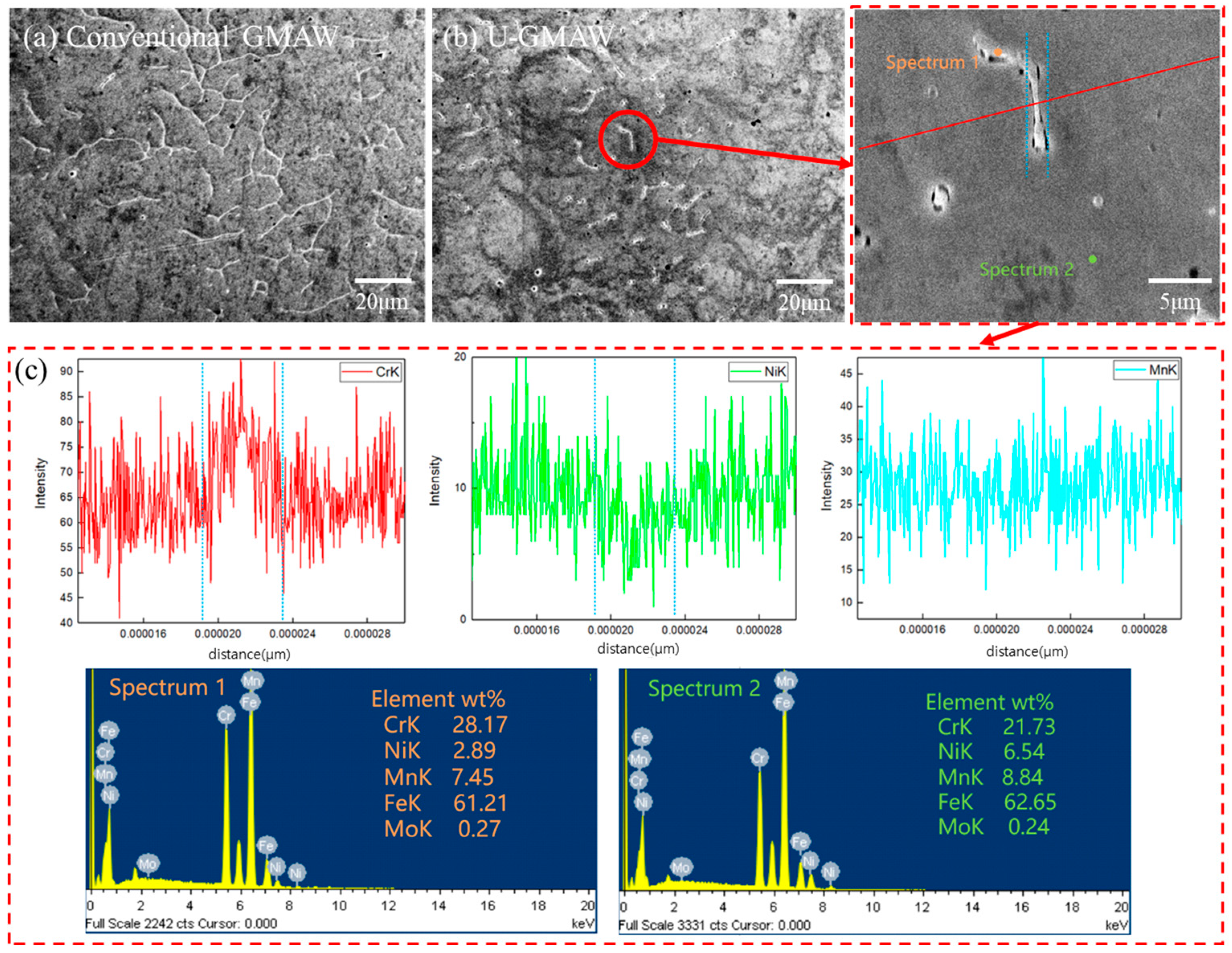
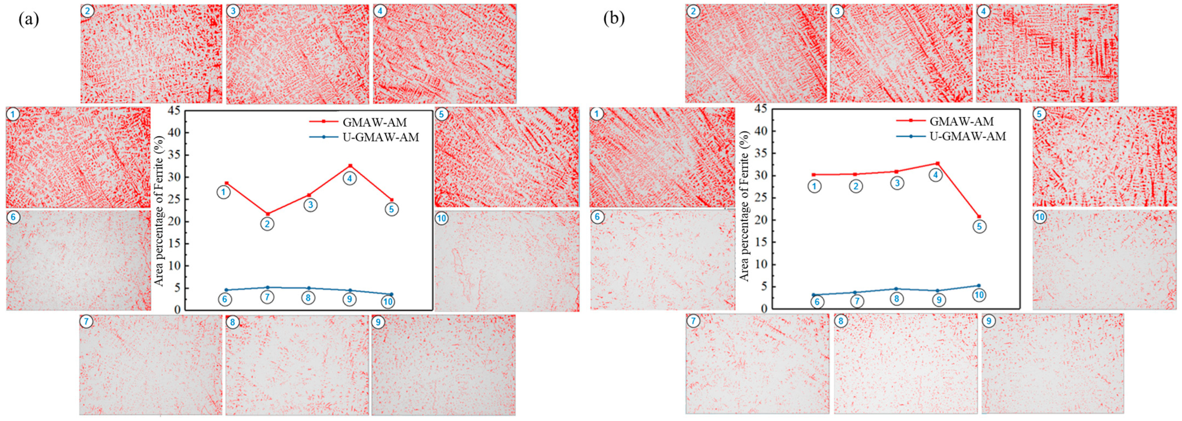
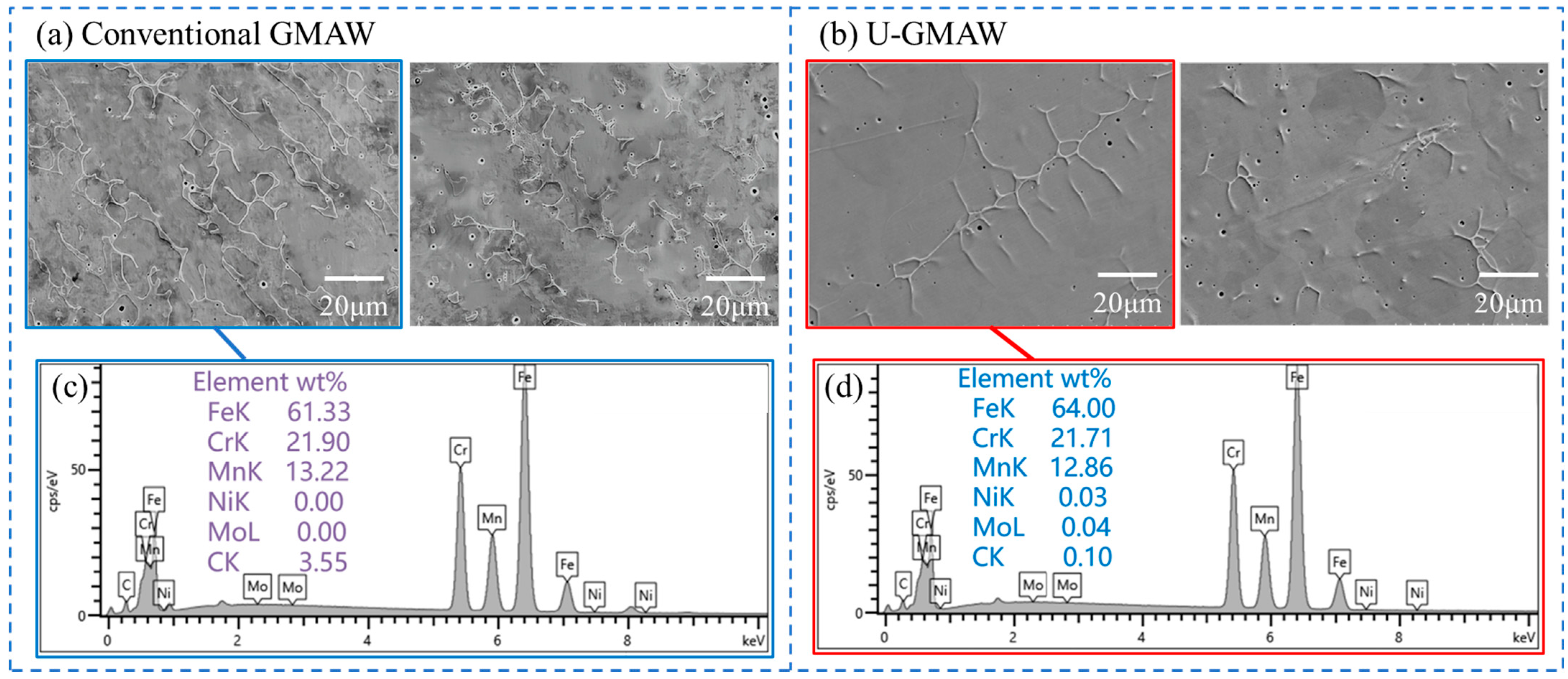
3.4. Microstructure of Conventional and U-GMAW-AM

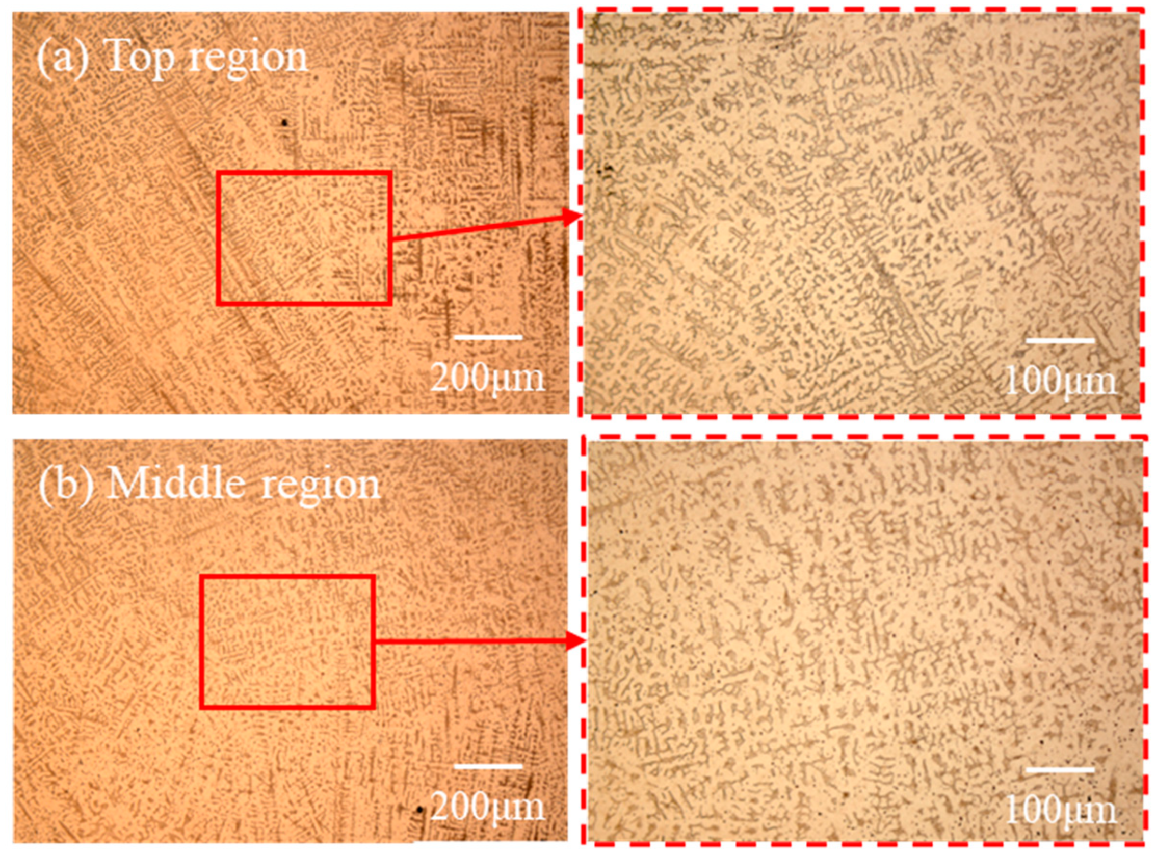
3.4.1. Microstructure of 0.35 wt.% Nitrogen Wire

The microstructures obtained under both metal transfer modes with conventional GMAW-AM exhibited morphological consistency, as shown in Figure 7. Dark dendritic crystals were uniformly distributed within the matrix. In the middle and top regions, primary dendrites were longer with abundant secondary dendrite arms, while the bottom region displayed multi-oriented dendritic structures. Elemental analysis of the welding wire was performed to calculate the Ni and Cr equivalents using the modified Schaeffler diagram [23]. Combined with microstructural observations, the results confirmed that the dark dendritic phase corresponds to α-ferrite, while the matrix phase consists of γ-austenite. During ferrite formation, Cr was enriched, whereas austenite-forming elements such as Mn, N, and Ni were rejected from the ferrite phase.
Figure 8 presents the metallographic structure of U-GMAW-AM specimens fabricated using the 0.35 wt.% nitrogen-containing wire. The microstructures in the middle and top regions were similar, with the black precipitated phase transitioning from an initial dendritic morphology to a more dispersed distribution. This transition suggests that ultrasonic energy partially disrupts dendritic growth, promoting structural refinement. Notably, in the bottom region, dendritic structures were completely absent and replaced by a uniform, light-colored phase, preliminarily identified as austenite. The use of a 304 stainless-steel substrate likely contributed to increased Ni content in the bottom region, which stabilizes austenite and influences phase development. To eliminate substrate-induced compositional effects, subsequent analyses focused exclusively on the intermediate and top regions.
Figure 9a,b compare the SEM microstructure of AM components with and without ultrasonic assistance. As illustrated in Figure 9c, point and line scanning EDS analysis was carried out to further determine the composition of the precipitated phase.

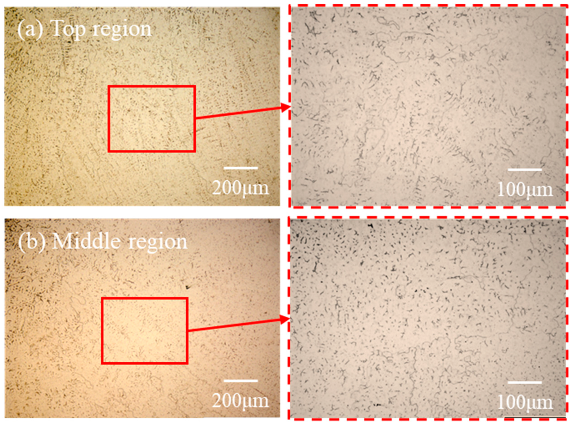
3.4.2. Microstructure of AM Components of 0.70 wt.% Nitrogen Wire

Conventional and U-GMAW-AM experiments were conducted using 0.70 wt.% nitrogen-containing wires at welding voltages of 24.5 V, 28 V, and 30 V. Due to a significant reduction in nitrogen content within the AM component at 24.5 V (short-circuit transfer mode), the analysis was restricted to the globular transfer regime (30 V), where metallographic morphology remained consistent. Figure 10 presents the microstructure observed at 30 V. Compared to the 0.35 wt.% nitrogen wire, the 0.70 wt.% AM component exhibited a higher volume fraction of skeletal ferrite uniformly distributed across the intermediate and top regions. The ferritic phase appeared coarser, with elongated primary dendrites and secondary dendrite arms in the top region, aligned with a uniform orientation. In Figure 10b, the dendrite arms in the middle region were shorter and oriented in multiple directions.
The microstructures of the U-GMAW-AM components at 30 V are presented in Figure 11.
Ultrasonic treatment effectively suppressed nitrogen loss (0.14% higher nitrogen content compared to conventional GMAW), leading to marked ferrite reduction and morphological refinement. As nitrogen is a strong austenite-forming element, it is preliminarily inferred that the retention of nitrogen in solid solution inhibits ferrite formation and promotes austenite development.
To further evaluate the effect of ultrasonic assistance on ferrite content, five randomly selected positions in the top and middle regions were analyzed using Fiji software (version 1.52) for image-based quantification, as illustrated in Figure 12.
To confirm that the reduction in ferrite content was due to nitrogen enrichment rather than differences in alloying element composition or segregation-induced phase transformations, EDS was conducted to assess the distribution and concentration. SEM images of microstructures fabricated with and without ultrasonic assistance at 30 V are shown in Figure 13a,b, while the corresponding EDS analysis results are presented in Figure 13c,d.

3.5. Mechanical Properties of Conventional and U-GMAW-AM

Tensile performance analysis was primarily conducted on three groups that demonstrated significant suppression of nitrogen evaporation with ultrasonic assistance. The experiment parameters and corresponding tensile strength and elongation values are presented in Table 4.
Hardness testing was performed along the centerline of the specimens, starting from the base metal and proceeding at 2 mm intervals. Figure 14 illustrates the hardness values at distinct positions relative to the fusion line.

4. Discussion

4.1. Influence of Ultrasonic Assistance on Nitrogen Pores and Nitrogen Content

Nitrogen content in AM components with and without ultrasonic treatment is shown in Figure 15. During the droplet transfer process and within the high-temperature molten pool, nitrogen atoms tend to aggregate and form nitrogen gas (N2), which escapes via bubble formation, leading to nitrogen loss and potential porosity defects. In conventional AM, nitrogen loss during short-circuit transfer was less than during globular transfer. The simultaneous increase in welding voltage and contact-tip-to-workpiece distance (CTWD) induces a transition from short-circuit to globular transfer mode. Due to the lower spatter generation during short-circuit transfer compared to globular transfer, a greater proportion of nitrogen-containing droplets can stably enter the molten pool.
After applying ultrasonic assistance, nitrogen loss was significantly reduced, as shown in Figure 15. For the 0.35 wt.% nitrogen wire, due to its low nitrogen content, there was limited nitrogen gas generation and aggregation within the weld pool, resulting in negligible macroscopic porosity. And no substantial improvement in nitrogen retention was observed under ultrasonic assistance.
For the 0.70 wt.% nitrogen wire at 24.5 V, almost no porosity was observed under conventional processing. The arc length decreased with reduced voltage, and 24.5 V corresponded to the first ultrasonic emission height (H1 = 14 mm). Although an ultrasonic power of 2 kW at H1 effectively suppressed nitrogen evaporation during metal transfer, the intense oscillation effect on the weld pool destabilized nitrogen atoms and accelerated nitrogen bubble formation, aggregation, and escape—exacerbating nitrogen loss. If the bubbles failed to escape in time, they remained in the solidified pool as macroscopic pores and defects.
At both 28 V and 30 V, the ultrasonic emission height was set to the second ultrasonic emission height (H2 = 20 mm). And the oscillation effect on the weld pool was appropriately moderated to achieve better control. The reduced instability of nitrogen atoms and decreased bubble formation and aggregation led to less nitrogen loss. Therefore, during globular transfer, nitrogen loss in the 0.70 wt.% nitrogen wire was effectively suppressed by minimizing nitrogen escape through optimized ultrasonic parameters.
In the GMAW-AM process for high-nitrogen steels, ultrasonic waves simultaneously act on both the arc zone and the molten pool. Assuming the alloy composition and temperature of high-nitrogen steel droplets remain constant during the brief droplet transfer period, the partial pressure of nitrogen becomes the dominant factor influencing nitrogen solubility [36]. Nitrogen dissolves in liquid iron as nitride ions, where it exists predominantly in atomic form [37].
N 2 g = 2 N
The equilibrium constant KN for the nitrogen dissolution reaction [38] remains constant at a given temperature and is expressed as follows:
K N = a N P N 2 / P 0 = f N % N P N 2 / P 0
where [% N] denotes the mass percentage of dissolved nitrogen, P N 2 is the partial pressure of nitrogen, and P0 is the standard atmospheric pressure (1.01325 × 10⁵ Pa). aN and fN are coefficients. Accordingly, the coaxial ultrasonic radiation pressure suppresses excessive expansion of nitrogen bubbles at their interfaces during droplet transfer, effectively reducing nitrogen loss.

4.2. Influence of Ultrasonic Assistance on Microstructure

4.2.1. Influence of Ultrasonic Assistance on Microstructure of 0.35 wt.% Nitrogen Wire

Ultrasonic treatment significantly influences the microstructure of AM components. As shown in the SEM image (Figure 9), conventional AM results in a continuous dendritic morphology of the precipitated phase, whereas ultrasonic assistance leads to noticeable dendrite fragmentation and a more dispersed distribution of the precipitated phase.
EDS line scanning analysis of the precipitated phase (Figure 9) reveals a localized Cr concentration increase of approximately 15% at the phase boundaries, accompanied by an 8% depletion in Ni. Mn concentrations remain consistent across both the matrix and precipitated phases. Point scanning results confirm this elemental redistribution, showing pronounced Cr enrichment and Ni depletion within the precipitated phase, while Mn levels remain largely unchanged. These findings identify the precipitated phase as α-ferrite embedded within a γ-austenite matrix. This phase distribution results from solidification dynamics: Ni supersaturation in the liquid phase promotes its diffusion into the austenitic matrix, whereas Cr, a ferrite-stabilizing element, diffuses from the matrix into the ferrite, producing substantial Cr/Ni concentration gradients during solidification.
The Schaeffler diagram [39] and improved DeLong diagram [40] predict post-weld phase compositions in stainless steels using chromium and nickel equivalents (Creq and Nieq). Meanwhile, the WRC-1992 diagram further refines these models by incorporating the characterization of nitrogen effects and non-equilibrium solidification behavior. Solidification modes are categorized based on the Creq/Nieq ratio: ratios below 1.25 correspond to the austenitic (A) mode; 1.25–1.48 indicates the austenite–ferrite (AF) mode; 1.48–1.95 represents the ferrite–austenite (FA) mode; and ratios above 1.95 correspond to the ferritic (F) mode. Creq and Nieq are defined by Equations (1) and (2) [41,42].
Creq = 1Cr + 1.5Mo + 0.48Si
Nieq = 1Ni + 30C + 30N + 0.15Mn − 0.0066Mn2
At 24.5 V, the Creq/Nieq ratios for the 0.35 wt.% nitrogen wire were 1.27 without ultrasonic treatment and 1.23 with ultrasonic treatment (corresponding to AF and F mode). At 30 V, the ratios were 1.35 and 1.29, respectively. Both fall within the FA solidification mode, consistent with microstructural and compositional observations. The transition in metal transfer mode induced by increased voltage resulted in varying levels of nitrogen loss. However, due to the initially low nitrogen content of the wire, the ultrasonic-assisted effect on nitrogen enrichment was limited.

4.2.2. Influence of Ultrasonic Treatment on Microstructure of 0.70 wt.% Nitrogen Wire

Ultrasonic treatment in the AM process of the 0.70 wt.% nitrogen wire exhibits a notable reduction in both the size and volume fraction of the ferrite phase during globular transfer. Statistical analysis of ferrite content reveals distinct phase evolution patterns: conventional AM produces 20~30% ferrite in the middle and top regions, whereas ultrasonic assistance reduces this to approximately 5% in both regions. From the SEM comparison in Figure 13a, conventional GMAW results in greater nitrogen loss, leading to coarse and densely distributed ferrite. In contrast, ultrasonic assistance significantly mitigates nitrogen loss, resulting in refined and fragmented ferrite with improved dispersion uniformity and reduced volume fraction.
EDS analysis confirms similar distributions of major alloying elements under both conditions (Fe ≈ 60%, Cr ≈ 21%, Mn ≈ 13%). While Cr is a potent ferrite stabilizer and Mn promotes austenite formation, their concentrations remain relatively unchanged and do not significantly influence ferrite morphology or content. Instead, the suppression of ferrite formation is primarily attributed to the reduction in nitrogen loss due to ultrasonic assistance. This phenomenon increases solid solution nitrogen content by approximately 15% compared to conventional GMAW (Table 3), effectively inhibiting ferrite nucleation and growth. Consequently, phase evolution is driven predominantly by nitrogen retention rather than by alloying element segregation or compositional differences.
At 24.5 V, 28 V, and 30 V, the Creq/Nieq ratios of the 0.70 wt.% nitrogen wire with and without ultrasonic treatment were 1.16 and 1.31 (corresponding to A and AF modes), 1.26 and 1.08 (indicating a transition from AF to A mode), and 1.33 and 1.06 (AF and A mode), respectively. These results align with nitrogen content measurements and microstructural observations.

4.3. Influence of Ultrasonic Treatment on Mechanical Properties

4.3.1. Tensile Properties

Tensile test analysis (Figure 16) reveals distinct mechanical property enhancements in U-GMAW-AM components. For specimens fabricated with 0.35 wt.% nitrogen-enriched wire, ultrasonic treatment improves ultimate tensile strength (UTS) by approximately 50 MPa and elongation by 27%, attributed to enhanced nitrogen content (0.02% increase) and microstructural refinement. For components produced with the 0.70 wt.% nitrogen wire, they exhibit even greater improvements under ultrasonic assistance: UTS increases by over 100 MPa at both tested voltages, while elongation doubles from 5% to 10%.
The improvement in the mechanical properties of components processed with ultrasonic assistance is governed by several interrelated mechanisms. Due to their small atomic radius (0.15 nm) [43], nitrogen atoms dissolve interstitially in the matrix, causing lattice distortion that impedes dislocation movement and thereby increases yield strength. Solid solution strengthening from nitrogen can be quantified as follows [44,45]:
σ s s = k N · N m
where [N] is the nitrogen concentration in the matrix, kN and m are coefficients, and m is approximately 0.5 for nitrogen [46,47]. As shown in Equation (5), the solid solution strengthening effect increases with nitrogen content, which is consistent with the observed tensile results.
FCC austenite offers superior ductility and fracture toughness compared to BCC ferrite due to its multiple slip systems. Excessive ferrite content reduces the overall plasticity of components, diminishes the solid solution strengthening effect of nitrogen (a potent austenite stabilizer), and may induce crack formation through compositional segregation or phase transformation stresses. Ultrasonic assistance effectively reduces ferrite content and promotes phase homogeneity, thereby improving both strength and ductility.
The fracture surfaces of specimens 5 (0.70 wt.%, 30 V, conventional GMAW-AM) and 6 (U-GMAW-AM) shown in Figure 17 reveal consistent ductile failure characteristics. At low magnification, extensive fibrous zones dominate the fracture edges, accompanied by pronounced shear lips and significant necking. High-magnification imaging reveals pore-aggregated regions characterized by large dimples surrounded by densely distributed smaller dimples, indicating localized plastic instability. The uniformly distributed elliptical dimples with moderate depth across the fracture surface reflect substantial plastic deformation and high material ductility.
Notably, nitrogen pores were also found in specimen 5, which directly correlate with its 12% lower ultimate tensile strength compared to specimen 6. Distinct tearing zones form around nitrogen pores—absent in non-porous areas—where localized metal tearing occurs during tensile loading. These pores act as intrinsic crack initiation sites and stress concentrators, promoting crack propagation and thereby reducing tensile strength due to porosity-related failure mechanisms.

4.3.2. Hardness

The hardness of high-nitrogen steel components is directly influenced by the solid solution nitrogen content, which indicates mechanical property uniformity. For components 1 and 2, hardness values increase with distance from the base metal, with minimal variation between the two specimens. The hardness of U-AM specimens is slightly higher due to enhanced nitrogen content and microstructural refinement. Notably, near the interface, specimen 2 demonstrates 18–22% greater hardness than specimen 1, attributable to ultrasonic-promoted interfacial fusion that facilitates nitrogen diffusion into the substrate, modifying local mechanical properties.
The hardness distribution and magnitude of components 3, 4, 5, and 6 are similar; however, the U-AM specimens demonstrate significantly higher hardness—exceeding a 25% increase—compared to their conventional counterparts. This improvement is primarily attributed to the substantially increased nitrogen content. The hardness values of the two groups increased by more than 25%, and the longitudinal hardness values showed a distribution pattern similar to components 1 and 2, gradually increasing with the increase in layers.

5. Conclusions

A coaxial ultrasonic-assisted process was used to address nitrogen evaporation and pore formation during GMAW additive manufacturing of high-nitrogen welding wire. This study investigated the effects of ultrasonic vibrations (0–2 kW) and welding voltages (24.5–30 V) on the microstructure, nitrogen content, and mechanical properties of HNS components fabricated with 0.35 wt.% and 0.70 wt.% nitrogen wires. The main conclusions are as follows:
  • The introduction of coaxial ultrasonic assistance into gas metal arc welding additive manufacturing (GMAW-AM) significantly alters molten pool geometry by increasing penetration depth while slightly reducing weld bead width. These changes promote enhanced interlayer fusion and dimensional consistency in multi-layer fabrication of high-nitrogen steels.
  • Ultrasonic treatment effectively suppresses nitrogen loss during metal transfer and solidification. For 0.70 wt.% nitrogen wires, ultrasonic application increased the final nitrogen content by up to 29.17% under optimized parameters. This is attributed to the acoustic radiation pressure and cavitation-induced effects that reduce droplet size and nitrogen bubble growth in the droplet transfer process, allowing them to escape from the molten pool, thereby stabilizing nitrogen in solution.
  • Microstructural analyses indicate that ultrasonic processing leads to significant refinement of dendritic ferrite in 0.35 wt.% nitrogen wires and a substantial reduction in both the content and coarseness of skeletal ferrite in 0.70 wt.% nitrogen wires. These microstructural changes reflect improved phase balance and enhanced austenite stability, which are attributed to increased nitrogen retention. By improving nitrogen retention, ultrasonic assistance modifies the solidification mode of high-nitrogen steel, which promotes interstitial solid solution strengthening, suppresses ferrite formation, and facilitates the development of finer, more homogeneous microstructures.
  • Mechanical testing confirms improvements in tensile properties and hardness after ultrasonic assistance. The 0.70 wt.% nitrogen components fabricated under ultrasonic conditions exhibited an ultimate tensile strength increase of over 100 MPa and a hardness increase exceeding 25%, primarily attributed to the ultrasonic-induced microstructural refinement and nitrogen retention.
  • The combined results demonstrate that ultrasonic-assisted GMAW-AM provides a novel approach for regulating nitrogen behavior in high-nitrogen steel additive manufacturing. By effectively suppressing nitrogen evaporation, this technique enhances nitrogen retention, refines the solidification microstructure, and improves mechanical performance. The underlying mechanism offers theoretical support for process–microstructure control and mechanical property improvement in arc-based additive manufacturing of nitrogen-rich steels.

Author Contributions

Conceptualization, C.F.; methodology, C.F., J.L. and Z.H. (Zhizheng He); formal analysis, J.L., Z.H. (Zhizheng He) and Z.H. (Zihuan Hua); investigation, J.L., Z.H. (Zhizheng He) and Z.H. (Zihuan Hua); resources, C.F.; data curation, J.L. and Z.H. (Zihuan Hua); writing—original draft preparation, J.L.; writing—review and editing, J.L., Z.H. (Zhizheng He), C.F.; visualization, J.L. and Z.H. (Zihuan Hua); supervision, C.F.; project administration, C.F.; funding acquisition, C.F. All authors have read and agreed to the published version of the manuscript.

Funding

This research was funded by the Taishan Industry Leading Talents Blue Talent Project, under grant number tsls20230607.

Data Availability Statement

The original contributions presented in this study are included in the article. Further inquiries can be directed to the corresponding author.

Acknowledgments

The authors gratefully acknowledge Zhanmin Chen (Shandong Huayuan Rigging Co., Ltd.) for his critical technical support and industrial expertise, which significantly enhanced the experimental rigor of this study.

Conflicts of Interest

The authors declare no conflicts of interest.

References

  1. Yun, P.; Song, L.; Zhao, L.; Chengyong, M.; Haiyan, Z.; Zhiling, T. Research status of weldability of advanced steel. Acta Met. Sin. 2020, 56, 601–618. [Google Scholar]
  2. Katada, Y.; Sagara, M.; Kobayashi, Y.; Kodama, T. Fabrication of high strength high nitrogen stainless steel with excellent corrosion resistance and its mechanical properties. Mater. Manuf. Process. 2001, 19, 19–30. [Google Scholar] [CrossRef]
  3. Svyazhin, A.; Kaputkina, L.; Smarygina, I.; Kaputkin, D. Nitrogen steels and high-nitrogen steels: Industrial technologies and properties. Steel Res. Int. 2022, 93, 2200160. [Google Scholar] [CrossRef]
  4. Harzenmoser, M. Welding of high nitrogen steels. Mater. Manuf. Process. 2004, 19, 75–86. [Google Scholar] [CrossRef]
  5. Muthu, S.M.; Veeman, D.; Vijayakumar, A.; Prabu, S.S.; Sujai, S.; Arvind, M.; Gobinath, E. Evaluation of metallurgical and mechanical characteristics of the ferritic stainless steel AISI 430 produced by GTAW-based WAAM. Mater. Lett. 2024, 354, 135362. [Google Scholar] [CrossRef]
  6. Akbarzadeh, E.; Yurtışık, K.; Gür, C.H.; Saeid, T.; Tavangar, R. Influence of shielding gas on the microstructure and mechanical properties of duplex stainless steel in wire arc additive manufacturing. Met. Mater. Int. 2024, 30, 1977–1996. [Google Scholar] [CrossRef]
  7. Yang, G.; Deng, F.; Zhou, S.; Wu, B.; Qin, L.; Zheng, J. Influence of shielding gas nitrogen content on the microstructure and mechanical properties of Cu-reinforced maraging steel fabricated by wire arc additive manufacturing. Mater. Sci. Eng. A 2022, 832, 142463. [Google Scholar] [CrossRef]
  8. Zhang, X.; Peng, Y.; Huang, Y.; Wang, K.; Kong, J.; Du, Z.; Wu, T.; Zhou, M. Precipitation characteristics and tensile properties of high-nitrogen chromium-manganese steel fabricated by wire and arc additive manufacturing with isothermal post-heat treatment. Mater. Des. 2023, 225, 111536. [Google Scholar] [CrossRef]
  9. Guo, S.; Li, Y.; Duan, M.; Wang, P.; Gu, J.; Peng, Y.; Liu, J.; Zhou, Q.; Wang, M.; Wang, K. Microstructure and mechanical properties of high nitrogen steel–high strength steel bimetallic multi-layered steels fabricated by plasma-arc additive manufacturing. Mater. Today Commun. 2023, 37, 107538. [Google Scholar] [CrossRef]
  10. Zhang, X.W. Application of metal additive manufacturing in aero-engine. J. Aerosp. Power 2016, 31, 10–16. [Google Scholar]
  11. Kai, T.; Wesling, V. The current state of research of wire arc additive manufacturing (WAAM): A review. Appl. Sci. 2021, 11, 8619. [Google Scholar] [CrossRef]
  12. Berns, H. Manufacture and application of high nitrogen steels. ISIJ Int. 1996, 36, 909–914. [Google Scholar] [CrossRef]
  13. Cui, B.; Liu, S.; Zhang, F.; Luo, T.; Feng, M. Effect of welding heat input on pores in laser-arc hybrid welding of high nitrogen steel. Int. J. Adv. Manuf. Technol. 2021, 119, 421–434. [Google Scholar] [CrossRef]
  14. Wang, L.; Li, Y.; Ding, J.; Xie, Q.; Zhang, X.; Wang, K. Problems in Welding of High Nitrogen Steel: A Review. Metals 2022, 12, 1273. [Google Scholar] [CrossRef]
  15. Liao, J. Nitride precipitation in weld HAZs of a duplex stainless steel. ISIJ Int. 2001, 41, 460–467. [Google Scholar] [CrossRef]
  16. Ogawa, M.; Hiraoka, K.; Katada, Y.; Sagara, M.; Tsukamoto, S. Chromium nitride precipitation behavior in weld heat-affected zone of high nitrogen stainless steel. ISIJ Int. 2002, 42, 1391–1398. [Google Scholar] [CrossRef]
  17. Gurrala, A.K.; Tirumalla, A.; Sheik, S.; Mohammed, R. Role of nitrogen shielding environment on microstructure and corrosion behavior of 2205 duplex stainless-steel A-GTA welds. Mater. Today Proc. 2022, 66, 595–601. [Google Scholar] [CrossRef]
  18. Zhang, Z.; Han, Y.; Lu, X.; Zhang, T.; Bai, Y.; Ma, Q. Effects of N2 content in shielding gas on microstructure and toughness of cold metal transfer and pulse hybrid welded joint for duplex stainless steel. Mater. Sci. Eng. A 2023, 872, 144936. [Google Scholar] [CrossRef]
  19. Zhang, Z.; Jing, H.; Xu, L.; Han, Y.; Zhao, L.; Zhou, C. Effects of nitrogen in shielding gas on microstructure evolution and localized corrosion behavior of duplex stainless steel welding joint. Appl. Surf. Sci. 2017, 404, 110–128. [Google Scholar] [CrossRef]
  20. Qiang, W.; Wang, K. Shielding gas effects on double-sided synchronous autogenous GTA weldability of high nitrogen austenitic stainless steel. J. Mater. Process. Technol. 2017, 250, 169–181. [Google Scholar] [CrossRef]
  21. Hertzman, S.; Pettersson, R.J.; Blom, R.; Kivineva, E.; Eriksson, J. Influence of shielding gas composition and welding parameters on the N-content and corrosion properties of welds in N-alloyed stainless steel grades. ISIJ Int. 1996, 36, 968–976. [Google Scholar] [CrossRef]
  22. Hosseini, V.A.; Wessman, S.; Hurtig, K.; Karlsson, L. Nitrogen loss and effects on microstructure in multipass TIG welding of a super duplex stainless steel. Mater. Des. 2016, 98, 88–97. [Google Scholar] [CrossRef]
  23. Speidel, M.O. New nitrogen-bearing austenitic stainless steels with high strength and ductility. Met. Sci. Heat Treat. 2005, 47, 489–493. [Google Scholar] [CrossRef]
  24. Liu, Z.; Fan, C.L. Design and evaluation of nitrogen-rich welding wires for high nitrogen stainless steel. J. Mater. Process. Technol. 2021, 288, 116885. [Google Scholar] [CrossRef]
  25. Wendler, M.; Weiß, A.; Krüger, L.; Mola, J.; Franke, A.; Kovalev, A.; Wolf, S. Effect of manganese on microstructure and mechanical properties of cast high alloyed Cr Mn Ni-N steels. Adv. Eng. Mater. 2013, 15, 558–565. [Google Scholar] [CrossRef]
  26. Cheng, B.S.; Wei, F.X.; Ramamurty, U. Ambient pressure fabrication of Ni-free high nitrogen austenitic stainless steel using laser powder bed fusion method. Addit. Manuf. 2022, 55, 102810. [Google Scholar] [CrossRef]
  27. Liu, Z.; Fan, C.L. Optimization of the microstructure and mechanical properties of the high nitrogen stainless steel weld by adding nitrides to the molten pool. J. Manuf. Process. 2020, 49, 355–364. [Google Scholar] [CrossRef]
  28. Evans, G.M. Effect of nitrogen on C-Mn steel welds containing titanium and boron. Weld. J. 1998, 77, 239-s. [Google Scholar]
  29. Li, J.; Li, H.; Liang, Y.; Liu, P.; Yang, L. The Microstructure and Mechanical Properties of Multi-Strand, Composite Welding-Wire Welded Joints of High Nitrogen Austenitic Stainless Steel. Materials 2019, 12, 2944. [Google Scholar] [CrossRef]
  30. Kumar, N.; Arora, N.; Goel, S.K. Study on metallurgical and mechanical aspects of GMA welded nitronic steel under the influence of weld quenching. J. Manuf. Process. 2020, 56, 116–130. [Google Scholar] [CrossRef]
  31. Sun, Q.J. Research on Ultrasonic-Arc Behaviors and Ultrasonic Assisted TIG Welding Method. Ph.D. Thesis, Harbin Institute of Technology, Harbin, China, 2010; p. 19. [Google Scholar]
  32. Fan, Y.Y. Research on Ultrasonic Assisted Gas Metal Arc Welding and Metal Transfer Behavior. Ph.D. Thesis, Harbin Institute of Technology, Harbin, China, 2011; pp. 19–21. [Google Scholar]
  33. Chen, C. Research on Pulsed Ultrasonic Assisted Arc Welding Characteristics. Ph.D. Thesis, Harbin Institute of Technology, Harbin, China, 2011; pp. 41–62. [Google Scholar]
  34. Luo, J.; He, Z.; Liu, Z.; Hua, Z.; Teng, B.; Fan, C. The Influence of Coaxial Ultrasound on the Droplet Transfer of High Nitrogen Steel GMAW Process. Materials 2024, 17, 5509. [Google Scholar] [CrossRef]
  35. GB/T 228.1-2021; Metallic Materials—Tensile Testing—Part 1: Method of Test at Room Temperature. Standards Press of China: Beijing, China, 2021.
  36. Sano, M.; Fujita, Y.; Mori, K. Formation of bubbles at single nonwetted nozzles in mercury. Metall. Trans. B 1976, 7, 300–301. [Google Scholar] [CrossRef]
  37. Ishii, F.; Ban-Ya, S.; Fuwa, T. Solubility of nitrogen in liquid iron and iron alloys containing the group VIa elements. Tetsu Hagane 1982, 68, 946–955. [Google Scholar] [CrossRef]
  38. Anson, D.; Pomfret, R.J.; Hendry, A. Prediction of the solubility of nitrogen in molten duplex stainless steel. ISIJ Int. 1996, 36, 750–758. [Google Scholar] [CrossRef]
  39. Schaeffler, A.L. Constitution diagram for stainless steel weld metal. Met. Prog. 1949, 56, 680. [Google Scholar]
  40. DeLong, W.T. Ferrite in austenitic stainless steel weld metal. Weld. J. 1974, 53, 273s–286s. [Google Scholar]
  41. Kotecki, D.J.; Siewert, T.A. WRC-1992 constitution diagram for stainless steel weld metals: A modification of the WRC-1988 diagram. Weld. J. 1992, 71, 171–178. [Google Scholar]
  42. Wu, T.; Liu, J.; Wang, K.; Wang, L.; Zhang, X. Microstructure and mechanical properties of wire-powder hybrid additive manufacturing for high nitrogen steel. J. Manuf. Process. 2021, 70, 248–258. [Google Scholar] [CrossRef]
  43. Gavriljuk, V.; Berns, H. High Nitrogen Steels: Structure, Properties, Manufacture, Applications; Springer Science & Business Media: Berlin/Heidelberg, Germany, 1999; pp. 2–4. [Google Scholar]
  44. Sabirov, I.; Murashkin, M.Y.; Valiev, R.Z. Nanostructured aluminium alloys produced by severe plastic deformation: New horizons in development. Mater. Sci. Eng. A 2013, 560, 1–24. [Google Scholar] [CrossRef]
  45. Ryen, Ø.; Holmedal, B.; Nijs, O.; Nes, E.; Sjölander, E.; Ekström, H.-E. Strengthening mechanisms in solid solution aluminum alloys. Metall. Mater. Trans. A 2006, 37, 1999–2006. [Google Scholar] [CrossRef]
  46. Reed, R.P. Nitrogen in austenitic stainless steels. Jom 1989, 41, 16–21. [Google Scholar] [CrossRef]
  47. Fleischer, R.L. Substitutional solution hardening. Acta Metall. 1963, 11, 203–209. [Google Scholar] [CrossRef]
Figure 1. Schematic diagram of U-GMAW setup.
Metals 15 00491 g001
Figure 2. Tensile test. (a) Sampling location; (b) dimensions; (c) post-fracture images of tensile specimens.
Metals 15 00491 g002
Figure 3. Nitrogen content test. (a) Oxygen, nitrogen, and hydrogen analyzer; (b) sampling location and specimen geometries.
Metals 15 00491 g003
Figure 4. Cross-section of weld bead with 0.70 wt.% nitrogen wire. (a) 24.5 V, 0 kW; (b) 24.5 V, 2 kW; (c) 28 V, 0 kW; (d) 28 V, 2 kW; (e) 30 V, 0 kW; (f) 30 V, 2 kW.
Metals 15 00491 g004
Figure 5. Statistical results of single-layer weld width and depth of conventional and U-GMAW. (a) Weld width; (b) weld depth.
Metals 15 00491 g005
Figure 6. Metallographic morphology of cross-section: (a,b) 0.35 wt.%, 24.5 V, 0/2 kW; (c,d) 0.70 wt.%, 24.5 V, 0/2 kW; (e,f) 0.70 wt.%, 30 V, 0/2 kW.
Metals 15 00491 g006
Figure 7. Microstructure of conventional GMAW-AM components with 0.35 wt.% nitrogen wire. (a) Top region; (b) middle region; (c) bottom region.
Metals 15 00491 g007
Figure 8. Microstructure of U-GMAW-AM components with 0.35 wt.% nitrogen wire. (a) Top region; (b) bottom region.
Metals 15 00491 g008
Figure 9. SEM image and EDS analysis of AM components with 0.35 wt.% nitrogen welding wire. (a) Conventional GMAW-AM; (b) U-GMAW-AW; (c) point and line scanning of precipitated phase.
Metals 15 00491 g009
Figure 10. Microstructure of conventional GMAW-AM components with 0.70 wt.% nitrogen wire at 30 V: (a) top region; (b) middle region.
Metals 15 00491 g010
Figure 11. Microstructure of U-GMAW-AM components with 0.70 wt.% nitrogen wire at 30 V. (a) Top region; (b) middle region.
Metals 15 00491 g011
Figure 12. Statistical results of ferrite proportion in middle and top regions. (a) Top region; (b) middle region.
Metals 15 00491 g012
Figure 13. SEM morphology and EDS analysis results of GMAW-AM and U-GMAW-AM. (a,c) SEM images and EDS results of conventional GMAW-AM; (b,d) SEM images and EDS results of U-GMAW-AW.
Metals 15 00491 g013
Figure 14. Hardness test results. (a) 0.35 wt.%, 24.5 V; (b) 0.70 wt.%, 28 V; (c) 0.70 wt.%, 30 V.
Metals 15 00491 g014
Figure 15. Results of nitrogen content test.
Metals 15 00491 g015
Figure 16. Statistical results of tensile test. (a) Tensile strength; (b) elongation.
Metals 15 00491 g016
Figure 17. Fracture morphology of specimens 5 and 6. (a) Conventional GMAW-AM; (b) U-GMAW-AM.
Metals 15 00491 g017
Table 1. Composition of high-nitrogen steel welding wires (wt.%).
ElementNCSiMnCrNiMoFe
Content0.350.0710.8328.8422.266.540.27Bal.
Content0.700.0720.43213.4221.900.300.04Bal.
Table 2. Experimental parameters for 0.70 wt.% nitrogen wire.
NumberVoltage
(V)
Wire Feeding Speed
(m/min)
Travel Speed
(mm/min)
Ultrasonic Power
(W)
124.573600
224.573602k
3287.53600
4287.53602k
5307.53600
6307.53602k
Table 3. Nitrogen content test results.
NumberNitrogen Content
(%)
Welding
Voltage
(V)
Ultrasonic Power
(kW)
Transfer ModeNitrogen Loss
(%)
10.3524.50short-circuit transfer0.04
220.02
3300globular transfer0.07
420.05
50.724.50short-circuit transfer0.14
620.21
7280globular transfer0.19
82short-circuit transfer0.09
9300globular transfer0.22
1020.08
Table 4. Results of tensile properties of conventional and U-GAM-AM.
NumberNitrogen
Content
(wt.%)
Voltage
(V)
WFS
(m/min)
Ultrasonic Power
(W)
Average Tensile Strength
(MPa)
Average
Elongation (%)
10.3524.570654.711.2
224.572k712.938.2
30.70287.50785.825.0
4287.52k953.827.5
5307.50786.522.0
6307.52k919.131.8
Disclaimer/Publisher’s Note: The statements, opinions and data contained in all publications are solely those of the individual author(s) and contributor(s) and not of MDPI and/or the editor(s). MDPI and/or the editor(s) disclaim responsibility for any injury to people or property resulting from any ideas, methods, instructions or products referred to in the content.

