Abstract
Italy is located in a very active seismic zone, and many earthquakes have marked the country, some of them in the recent past. In order to take adequate measures of seismic prevention and protection, in the last decades, the Italian Civil Protection Department (DPC) initiated a survey and introduced a specific form for the quick and/or post-seismic assessment of buildings. This is useful to obtain statistics on the types of structures and their vulnerability and a judgement on the damage, leading to a decision about the possibility of reuse and/or the level of retrofitting to be applied. Those activities have been developed since the beginning of 2000. This task is currently carried out by the Italian DPC-ReLUIS project research, line WP2 on the inventory of building structures, setting up the CARTIS form for any structural type, like masonry, reinforced concrete, precast concrete, steel, and timber structures, the latter being mainly related to large span buildings, extensively used in Italy. In this context, the paper presents the first draft of the CARTIS form for large span timber structures that provides a general description for typical structural schemes, through the singular points commonly considered as seismic structural vulnerabilities. Moreover, the statistics on timber large span structures based on a sample of 10 buildings is presented.
1. Introduction
The seismic vulnerability evaluation of a structure through quick level methods implements empirical approaches [1,2,3], based on the analogy with structures of the same type, having undergone seismic damage. The “quick” level, useful at territorial scale, is based on the identification of simple elements significant for the structures vulnerability, which are collected in specific survey form. Then, the procedure furnishes a vulnerability index through the weighted combination of the vulnerability elements. The methodology is a valuable tool that can be generally adopted in any kind of vulnerability investigation of buildings [4,5].
Therefore, the quick level approach for the seismic vulnerability assessment is aided by survey forms, describing the main features of a building that influence the seismic behavior of the construction, which represent vulnerability elements.
In Italy, the first vulnerability forms were prepared by the National Group for the Defense against Earthquakes (GNDT) for post-earthquake surveys [3]. They were conceived to detect vulnerability and damage, without any specific concern for building usability.
A specific tool (AeDES) for damage assessment, short term countermeasures for damage limitation, and evaluation of the post-earthquake usability of ordinary buildings was created in 1996/7 to be used by the Italian Civil Protection Department (DPC) after the destructive earthquake Umbria-Marche in 1997. Since then, it was improved based on the experience acquired in subsequent seismic events, i.e., Molise 2002, L’Aquila 2009, and Emilia-Romagna 2012, from the AeDES 05/2000 up to the AeDES 07/2013 versions.
During the L’Aquila earthquake, the form was officially used as a tool for the damaged building census (OPCM 3753, 6 April 2009) and introduced as annex in the DPCM 5/05/2011, as a first level form for the quick assessment of post-earthquake damage, first interventions, and usability judgments for ordinary buildings. Subsequently a survey of the Italian building heritage has started, aiming at the inventory of recurrent structural types to obtain statistics on the structure types and judgements on the related damage. This kind of survey can be used to decide about the possibility to use the building and/or about the level of retrofitting to be applied. The form for the quick post-seismic assessment of buildings formerly concerned the most common constructions, manly masonry buildings. Afterward, it has been adapted and extended also to large-span or prefabricated structures (GL-AeDES January 2014), mainly made of precast reinforced concrete. A further evolution is the CARTIS form (typological–structural characterization of urban compartments; [3]), in development within the DPC-ReLUIS project, working package WP2—Inventory of structural type and existing building. A specific form is devoted to large span structures, including timber ones. The latter category of constructions is more and more spread in the built heritage, and it is under the attention of the international scientific community. This is testified by several recent studies [5,6,7,8,9,10,11,12,13,14,15,16] dealing with the most common structural types and the robustness assessment of existing timber large span structures. With specific regards to the timber structural roofs and floors of monumental buildings, survey forms have been also implemented within the European project COST Action FP1101 [17,18].
In this paper, a sample of 10 large span timber structures is presented that is representative of the most common types of timber constructions for public, sports, or productive uses in Italy. Therefore, the CARTIS form preliminary proposal for large span timber structures is illustrated and applied to the sample of buildings. Based on this, the typological analysis of the large span timber structures and the related statistics is presented.
2. A Survey on Long-Span Timber Structures in Italy
2.1. Overview of the Sample
Timber long-span building stock in Italy was analyzed, selecting 10 structures from a sample of 101 buildings supplied by Rubner Holzbau for a study on typical structural systems and seismic vulnerabilities [14].
The structures of the sample are selected to be as close as possible to the epicenters of the last three main earthquakes that occurred in Italy: Abruzzo 2009, Emilia 2012, and central Italy 2016. This choice was carried out in order to employ the sample in further analyses on damages occurred and on possible vulnerabilities against earthquakes.
The sample represents the structures built in the period 1981–2014. In order to identify the seismic zone in the national context, in Figure 1a, the epicenters of Italian earthquakes with a magnitude greater than 5.5 in the period 1000–2014 are shown. The distribution of the case studies on the territory is shown in Figure 1b, taken from the ShakeMap service provided by the National Institute of Geophysics and Volcanology (INGV), which shows the intensity curves of earthquakes.
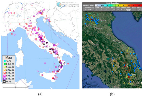
Figure 1.
(a) Epicenters of the Italian earthquakes with moment magnitude greater than 5.5 in the period 1000–2014 and (b) sample distribution in Italy as respect to the intensity contours of Abruzzo 2009, Emilia 2012, and central Italy 2016 earthquakes.
In particular, the following 10 structures were analyzed in this work (Figure 2):
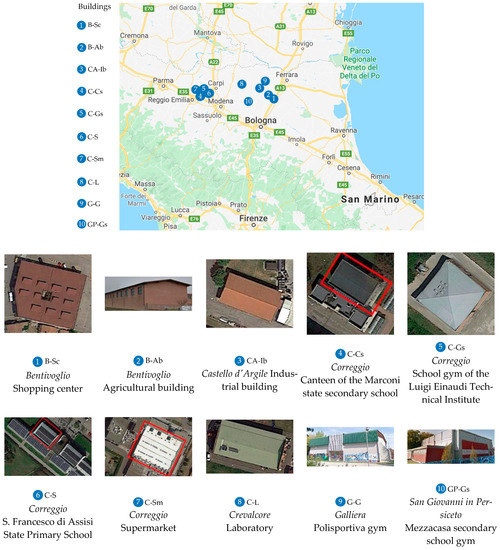
Figure 2.
The sample of buildings.
- (1)
- Bentivoglio—Shopping center (B-Sc);
- (2)
- Bentivoglio—Agricultural building (B-Ab);
- (3)
- Castello d’Argile—Industrial building (CA-Ib);
- (4)
- Correggio—Canteen of the Marconi state secondary school (C-Cs);
- (5)
- Correggio—School gym of the Luigi Einaudi Technical Institute (C-Gs);
- (6)
- Correggio—S. Francesco di Assisi State Primary School (C-S);
- (7)
- Correggio—Supermarket (C-Sm);
- (8)
- Crevalcore—Laboratory (C-L);
- (9)
- Galliera—Polisportiva gym (G-G);
- (10)
- San Giovanni in Persiceto—Mezzacasa secondary school gym (GP-Gs).
Looking at the utilization of these structures (Figure 2), agricultural or commercial buildings and school gyms represent 65% of the sample; the remaining part consists of sports halls, auditoriums, tourist centers, and other destinations of use. The information retrieved for each structure was detected from the documents provided by Rubner Holzbau, the executive drawings in every case, and the technical reports when needed.
The following section describes the most common structural types, taken from the analysis of the sample buildings under study.
2.2. Structural Systems
2.2.1. General Features
Among the sample, the recurrent structural types (91 cases) present a timber roof supported by reinforced concrete (r.c.) or steel vertical elements and only in a very low number of structures by masonry walls. In the remaining 10 cases, the entire load-bearing system is composed of timber elements.
The surfaces covered by the roof structures are distributed almost on every range of dimensions up to 13,871 m2. In most cases (73 of 101), only one nave is detected, whereas the remaining cases show up to five naves. The lengths of the main beams range between 6 to 51 m, more frequently between 10 to 30 m. Span between main beams is in the range of 1 to 32 m. Average height from ground level ranges between 3 to 14 m.
Three main static schemes are detected: portals with columns fixed at the base and hinged main beams; three-hinged arches; and three-hinged arches with beam to column moment resistant connections. In addition to these three schemes, six structures show a shape and a distribution in plan of the load-bearing elements that are unique and not observed also outside the survey.
The roof bracing system is generally realized by X steel braces, rods, or strips. Furthermore, timber linear elements are used in some cases as bracing system, either with single diagonal or K scheme. In 15 cases, with restraints along the entire perimeter of the building or in special schemes, like a circular shape in plan with main beams distributed on the rays; braces are not present because they are unnecessary.
2.2.2. Portals with R.C. or Steel Columns Fixed at the Base Supporting Timber Roofs
Among the sample, 91 structures present r.c. or steel vertical elements and a timber roof, with the columns fixed at the base and the main beams hinged to the top of the columns. Indeed, only six more cases include timber (glulam) columns.
The example reported in Figure 3 is a school gym in Carpi (MO), built in 1995. The structure is a r.c. frame that supports timber main beams with a span of about 26 m and secondary beams 5 m long, covering an overall area 26 × 30 m2. The connection is assembled through two dowels on each support (Figure 3d). The roof bracing system is realized with steel rods, cross arranged.
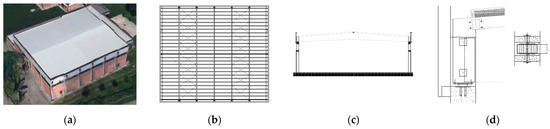
Figure 3.
School gym in Carpi (MO, 1995): (a) external view, (b) plan view, (c) section along main beams and (d) detail of the connection between column and main beam (courtesy of Rubner Holzbau).
2.2.3. Three-Hinged Arch
Among the sample, two buildings have a three-hinged arch structural system with two main monolithic beams for each portal.
The example shown in Figure 4 is a sports hall in Mirandola (MO), built in 1985. Each arch has a span of about 37 m, and the secondary beams are 7.75 m long; the total covered surface is 37 × 46.5 m2. The arch hinges are assembled using bolted connections (Figure 4d). The roof bracing system is made of cross-arranged teel bars.
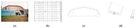
Figure 4.
School gym in Mirandola (MO, 1985): (a) external view, (b) plan view, (c) section along main beams, and (d) detail of the connection between column and main beam (courtesy of Rubner Holzbau).
2.2.4. Three-Hinged Arch with Beam to Column Moment Resistant Connection
Among the sample, two buildings present a three-hinged arch system with a moment resistant connection between column and beam, realized through dowel type connectors distributed in a circular radial configuration (Figure 5d).
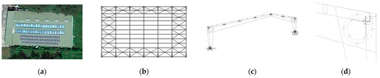
Figure 5.
Pool in Acquasanta Terme (AP, 2006): (a) external view, (b) plan view, (c) section along main beams, and (d) detail of the connection between column and main beam (courtesy of Rubner Holzbau).
The example reported in Figure 5 is a pool in Acquasanta Terme (AP), built in 2006. Each arch has a span of about 31 m, and secondary beams are 6 m long, covering an overall area of 31 × 36 m2. The roof bracing system is realized with steel rods.
3. The CARTIS Large Spans Form
3.1. Overview of the CARTIS Large Spans Form
The first level CARTIS form was designed to provide information on the different types of buildings commonly found in municipal (or province) or sub-municipal areas (districts), characterized by a homogeneous structural typology, construction age, types, and similar structural techniques. The goal is to define an organized database to collect the typological and structural characteristics of the buildings and, therefore, to quantify the exposure on a territorial scale.
The CARTIS form is based on the extensive experience acquired in the development and application of the AeDES form (Section 1), although the contents are different. It is divided into the following four sections:
Section 0: for the identification of the municipality (or province) and districts;
Section 1: for the identification of each prevalent constructive type within the districts;
Section 2: for the identification of the general characteristics of the constructive types analyzed;
Section 3: for the characterization of the structural elements of the constructive type analyzed.
Below, “CARTIS Large Spans form [19]: 1st level form for the typological structural characterization of large span buildings” (Annex A and B) is described in more detail. In particular, it consists of two main parts. The first part, nine pages and three sections, is related to the building scale, focusing on the single building (called “Building”, Annex A), and it is aimed at the identification of all the structural features. The second part, 14 pages and three sections, is related to the territorial scale, focusing on the district area (called “Districts”, Annex B), and it is aimed at identifying the structural types, materials, construction technologies, and state of conservation of the buildings, which are recurrent and characterize the specific district, for the census of structural types of existing constructions.
The CARTIS form provides a general description of the buildings, starting from the geographical, administrative, and urban localizations, going through the identification of the constructional type (masonry, reinforced concrete, steel, timber, and precast reinforced concrete), up to roofs or foundations, to finish with other information concerning regularity, openings, state of conservation, type of stairs, and type of past interventions. The greatest evidence is always given to the seismic vulnerability elements. The form is divided in the main sections and subsections listed in the following Table 1. It is at a validation stage of the preliminary version. In Figures 7, 9, 11, 16, 19, 21, and 25, the English version of the sections 0, 1A, 1B, 2A, 2B, 2C, and 3, respectively, belonging to the CARTIS “Buildings”, is provided.

Table 1.
Contents of the CARTIS form.
In particular, with regard to the CARTIS: “Buildings” (Annex A, [19]), Section 0 “Identification of municipality and building” (Section 4.2, Figure 7) collects the following data, subdivided in subsections: (a) localization; (b) identification data of the ReLUIS research unit (UR), filling the form based on the investigation, such as the UR code, affiliation, qualification; (c) identification data of the technician of the municipality interviewed; and (d) identification data of the building, such as class of use, code of use, and position of the building, if it is isolated, internal, external, or in a corner.
Section 1A, “Identification of the building constructive technology” (Section 4.3, Figure 9), allows the selection of the appropriate technology (r.c., precast r.c., steel, timber, masonry, composite steel-r.c., other material to be specified) associated to the structural elements, such as vertical and horizontal elements, roof, and foundation, identifying a homogeneous or mixed system.
Section 1B, “Identification of the building typology” (Section 4.4, Figure 11), collects general metrics data, such as number and span of naves and bays, column height, together with information about the sub-systems, such as the type of vertical seismic resistant system and connection with the horizontal floors, the presence and type of bracing system and members, as well as of anti-seismic devices, the type of roofing system, closing elements, and foundations structures.
Section 2A, “Description of the building” (Section 4.5, Figure 16), collects metrics data of the building, such as number of stories and underground stories, average inter-story heights, maximum column height, and average story area (m2). Age of the building, use, and exposure, such as type and percentage of use, as well as ownership (if public or private) are also requested.
Section 2B, “Presence of blocks added to the main structure” (Section 4.6, Figure 19), allows the identification of the position with respect to the main structure, the features of the possible added blocks, selecting the appropriate constructive technology of the structural components, the metrics data, the function, and the connection both to the main structure and between blocks.
Section 2C, “Typology of connections, panels, special loads, other non-structural elements” (Section 4.7, Figure 21), allows the definition of the type of connection between structural elements (foundation to column, column to beam or panels, beam to floor, beam to roof or column to roof, column to panels, panels to structure), the type of panels, the special loads, and the presence of other non-structural elements (like tanks, pipelines, silos, dangerous materials, and walkways for equipment connecting systems).
Section 3, “Other information” (Section 4.9, Figure 25), collects data about regularity in plan and in elevation, opening in façade, and state of conservation of the structural and non-structural parts of the building.
With regard to the CARTIS: “Districts” (Annex B, [19]), in particular Section 0, “Identification of the municipality (or province) and districts”, collects the following data, subdivided in subsections: (a) localization; (b) general data, such as number of inhabitants, year of first seismic classification, and number of buildings; (c) number of homogeneous districts; (d) identification data of the ReLUIS research Units; (e) identification data of the technician of the municipality interviewed; (f) constructive technologies present in the district; and (g) urban plan with delimitation and numbering of districts.
Section 1 “Identification of the constructive technology” allows the selection of the appropriate technology (masonry, r.c., steel, precast r.c., or timber) and the corresponding code; further, it assesses the position in the urban context (isolated or in aggregate buildings, either statically independent or connected). The picture should be provided.
Section 2, “General features”, collects metrics data, such as number of stories, number of underground stories, average inter-story height, maximum column height, average story area (m2); age of construction and of possible retrofitting; exposure, such as destination of use (residential, productive, commercial, offices, public services, deposit, strategic, touristic, parking, sports, and expositions); number of units of use; percentage of use; number of occupants in service and maximum ones; and percentage of public and private properties. Plan and section drawings are also required.
Section 3A, “Characterization of masonry type”, collects data about structural layout, masonry features, presence of rubble masonry, transversal connections, ring beams, buttress, masonry thickness, slab and vaults features, mixed constructions, mortars, colonnades, loggias, and other vulnerability elements.
Section 3B, “Characterization of reinforced concrete type”, collects data about structural layout and type, presence of separation joints, structural bow windows, frames in one direction, stocky members, infill walls, column sizes and reinforcing bars, and slab type.
Section 3C, “Characterization of steel type”, collects data about structural layout, structural system in elevation as respect to the floor slab type, structural member and bracing system types, presence of anti-seismic devices, and type of joint connections.
Section 3E, “Characterization of precast reinforced concrete type”, is similar to the previous section 3C for steel structures. Type of pre-stressing system should be also specified.
Section 3F, “Roofs and foundations”, collects data describing roofs, such as overall stiffness, maximum span, presence of in plan braces, type of system (single or double layouts of main members, either with solid section or hollow section or truss, plane or simple or double curvature layout, presence of ties, and thrusting elements), type of closing elements (horizontal or pitched floor, shed, skylight, adjacent or spaced tiles, vaults, and light elements), as well as data related to the type of foundation (shallow, deep, continuous, or discontinuous).
Section 3G, “Other information”, is related to the in plan and in elevation regularities requirements, percentage of openings in the façades, state of conservation of structural and non-structural elements (poor, medium, or good), possible typical structural retrofitting interventions (local, seismic improvements, and seismic upgrading), and type of stairs (flying slab, knee beam and cantilever steps, timber stairs, and flying buttress).
The specific Section 3D, focusing on timber constructions, is detailed in the next section.
3.2. The Draft CARTIS Large Spans Form for Timber Structures
Previous sections from 0 to 2, 3F, and 3G are general, to be applied to any type of construction, including timber structures. The specific “Section 3D” for the characterization of timber structures [19], which is now under evaluation, is illustrated hereafter, and the English version is provided in Figure 6. It has to be noticed that the square box can be selected for the multiple choice, while the circle is for a single choice.
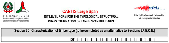
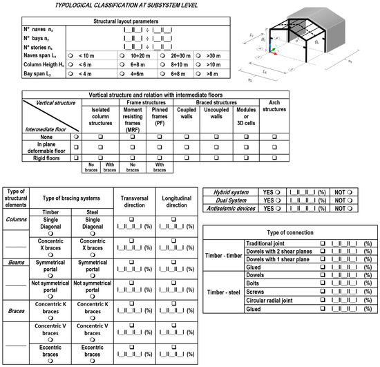
Figure 6.
Section 3D CARTIS-Districts: Characterization of timber type (English version [19]).
Firstly, the reference general timber structure is presented, where the main structural parameters are given, such as the number of naves nx, bays ny, and stories ns, the overall sizes, like span Lx, height Hc and bay span Ly. Subsequently the types of vertical seismic resistant systems, either isolated column structures; frame structures (moment resisting frames or pinned frames), both with and without bracing systems; braced structures (coupled walls, uncoupled walls, modules, or 3D cells); or arch structures (three hinged arch, truss arch …) are referred to.
Then, type of the structural elements, such as columns, beams, and braces, through the indication of the recurrent sections, can be specified, together with the bracing systems, such as single diagonal, concentric X, K, or V braces configurations, eccentric braces, symmetric or not symmetric portals with the corresponding percentage in transversal and longitudinal directions. They can be either hybrid, which integrate two or more technologies, or dual, which are composed by complementary systems, possibly equipped with antiseismic devices.
Finally, joints and connections can be described, considering the type of connection (timber–timber or timber–steel), the number of shear planes, and the type of connectors (nails, bolts, dowels, screws, or circular radial joints).
4. Typological Statistical Analysis of Timber Large Span Structures Based on the CARTIS Form
4.1. Metodology of Analysis
The sample case studies were analyzed with the aim, on one hand, of creating an inventory of the large-span timber buildings, and, on the other hand, of carrying out a statistical study based on the compilation of the CARTIS form, providing a general description for typical structural schemes. Therefore, the procedures for the statistical elaboration of the data characterizing the structures belonging to the sample are developed, implementing the CARTIS large span form, which constitutes a useful tool to identify the large-span structural types and their recurring peculiarities. Hereafter the statistical analysis is provided with reference to each significant section of the CARTIS Building form and the 3D section of the CARTIS District form filled for the case studies.
4.2. Section 0: CARTIS-Building: Identification of Municipality and Building
The English version (E.v.) of the Section 0 is presented in Figure 7.
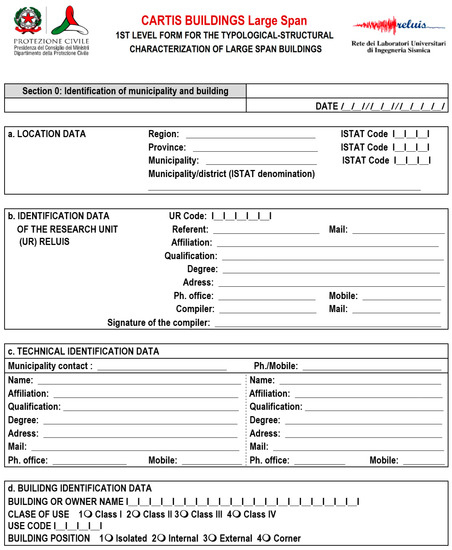
Figure 7.
Section 0 CARTIS-Building: Identification of municipality and building (English version [19]).
Seismic Location of the Building
The construction is localized through the ISTAT (National Institute of Statistics) codes. It is possible to associate the construction site with the Italian seismic zones. The classification into seismic zones is available on the “Civil protection” website [20] through the document “Seismic classification by municipality 2020”. All the buildings analyzed (100%) belonging to the sample are in seismic zone 3, based on the seismic classification of the Italian territory (with Peak Ground Acceleration, PGA, ranging between 0.05 and 0.15 g) (Figure 8a).
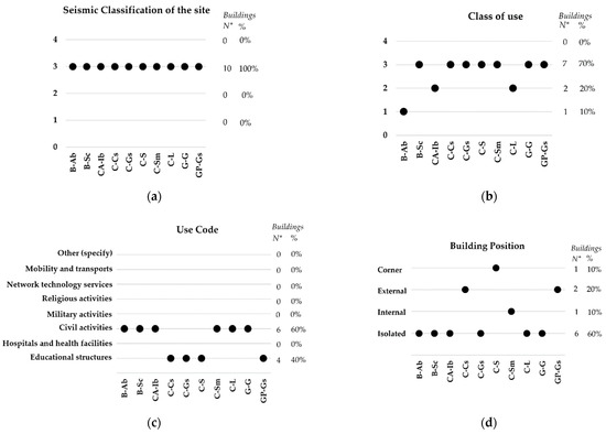
Figure 8.
Section 0 CARTIS-Building. Location and Building Identification Data: (a) Seismic classification of the site; (b) Class of use of the building; (c) Use code of the building; and (d) Building position.
Building Identification Data
The building is identified through the class of use, the code of use, and the position of the building (Figure 7 and Figure 8).
The classes of use are defined on the basis of the activity carried out in the building and the number of people who may be in the building, according to the Italian technical standard for constructions NTC2018 [21], in order to take into account the consequences of a damage or a collapse of the building on the occupants, the activity, or the system that the building is part of. The classes of use are defined hereafter:
Class I: Buildings with only occasional presence of people; agricultural buildings.
Class II: Buildings with normal crowd, without dangerous contents for the environment and without essential public and social functions; industries with activities that are not dangerous for the environment.
Class III: Buildings with significant crowd; industries with activities dangerous for the environment.
Class IV: Buildings with important public or strategic functions, also with reference to the management of civil protection in the event of a disaster; industries with activities that are particularly dangerous for the environment.
Most of the buildings, seven out of 10 (70%), are classified in category 3, since they have public use (supermarket, public services, etc.; Figure 8b); two buildings (20%) are classified in category 2, and only one building (10%) is classified in category 1.
The code of use, as defined in [22], should be assigned only to buildings that have a public service activity, and it is applied to facilitate the identification of buildings with public service functions in the database. In particular, four out of 10 buildings (40%) can be classified as educational structures (schools and gyms), and six out of 10 buildings (60%) are classified in the "civil activities" category (agricultural buildings, shopping centers, industrial buildings, supermarkets, and laboratories; Figure 8c).
The buildings are also characterized based on the position with respect to any other contiguous building (isolated, internal, external, or corner). The case studies mainly concern isolated buildings, but some of them are part of larger complexes, such as the schools (Figure 8d). In particular, six buildings (60%) are isolated and two buildings (20%) are external, while only one building (10%) is at the corner, and another one (10%) is internal.
4.3. Section 1A CARTIS-Building: Identification of the Building Constructive Technology
The English version of Section 1A is presented in Figure 9. For the technological identification, the material of each structural element is detected.
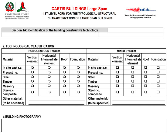
Figure 9.
Section 1A CARTIS-Building: Identification of the building constructive technology (English version [19]).
In Figure 10a, the material of the structural elements identified in the form is indicated for each case study. The structural system is recognized as mixed if it has structural elements with different materials. In particular, the vertical elements are made of r.c. for four out of 10 buildings (40%), in precast r.c. for two out of 10 buildings (20%), in steel for one out of 10 buildings (10%) and in timber for one out of 10 buildings (10%). Only one out of 10 buildings (10%) has a timber intermediate floor. In nine buildings (90%) the roofs are characterized by a timber structure, while one building (10%) has a mixed steel and timber structure. The foundations of the buildings are just assumed as in reinforced concrete, since they cannot be inspected at this level of analysis. The percentages shown in Figure 10a refer to the total number of structural elements made with the same technology (i.e., material). Therefore, 63% of the identified structural elements are made of timber, 21% of r.c., 11% of precast r.c., and 5% of steel. In the same figure, the type of element, such as vertical or horizontal intermediate elements, roof, or foundation, is reported through different columns for every case study related.
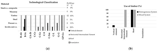
Figure 10.
Section 1A CARTIS-Building: (a) Technological classification; (b) Use of timber for the structural elements.
For evaluating the use of timber as a structural material for the building elements, the corresponding percentages are shown in Figure 10b, distinguishing both homogeneous and mixed systems.
It must be pointed out that timber is mainly used for the roof structure and the inter-story floors, with the vertical structure mainly made of reinforced concrete.
4.4. Section 1B CARTIS-Building: Identification of the Building Typology
The English version of the Section 1B is presented in Figure 11.
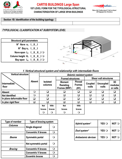
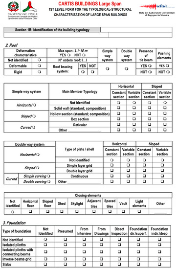
Figure 11.
Figure 11. Section 1B CARTIS-Building: Identification of the building typology (English version [19]).
Structural Grid Parameters
The geometrical data defining the structural layout are represented through five parameters, related to the overall size of the building (Figure 11). Figure 12 shows, for each case study, the number of naves nx in the transverse x-direction and the number of bays ny in the longitudinal y-direction, with the corresponding percentages.
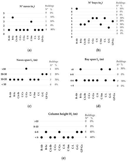
Figure 12.
Section 1B CARTIS-Building. Structural grid parameters: (a) Number of naves; (b) Number of bays; (c) Naves length; (d) Bay span; (e) Column height.
In particular, in the x-direction, eight out of 10 buildings (80%) consist of a single nave, one out of 10 buildings (10%) consists of four naves, and one out of 10 buildings (10%) consists of three naves. Additionally, in the y-direction, three out of 10 buildings (30%) consist of four bays, three out of 10 buildings (30%) consist of six bays, two out of 10 buildings (20%) consist of five bays, one building out of 10 (10%) consists of three bays, and one building out of 10 (10%) consists of nine bays (Figure 12a,b).
In the x-direction, seven out of 10 buildings (70%) have a span Lx ranging between 10 and 20 m, two out of 10 buildings (20%) between 20 and 30 m, and one out of 10 buildings (10%) greater than 30 m. The size is therefore always greater than or equal to 10 m, with a maximum value of 47 m. In the y-direction, the spacing between the bays ranges between 4 and 6 m for seven out of 10 buildings (70%) and is greater than 8 m for three out of 10 buildings (30%; Figure 12c,d). The span mainly ranges, therefore, between 4 to 6 m, and it reaches a maximum of 8 m.
The columns height is less than 6 m for six out of 10 buildings (60%) and ranges between 6 and 8 m for four out of 10 buildings (40%). The height is therefore mainly less than 6 m with a maximum value of 8 m (Figure 12e).
Vertical Structural System and Relationship with Intermediate Floors
Figure 13a shows the vertical seismic-resistant system. In particular, for three out of 10 buildings (30%) it consists of uncoupled walls; for one out of 10 buildings (10%) of uncoupled walls and isolated columns; for four out of 10 (40%) of isolated columns; and for two out of 10 buildings (20%) of moment resisting frame.
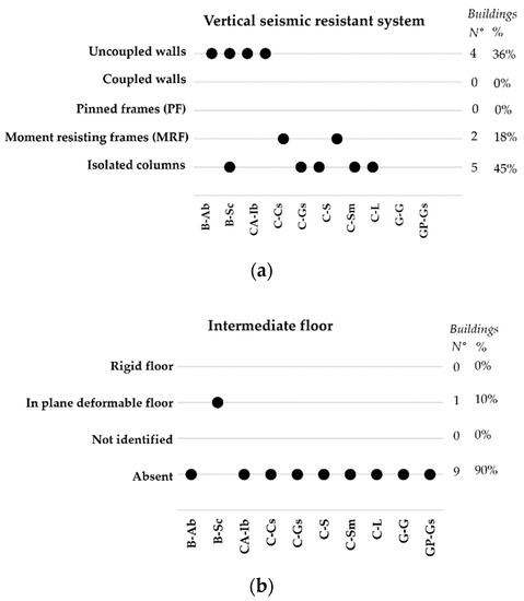
Figure 13.
Section 1B CARTIS-Building. Vertical structural system and relationship with intermediate floors: (a) Vertical seismic-resistant structure; (b) Intermediate floor.
Figure 13b shows the types of intermediate floors, which are mainly absent in the sample analyzed, since nine out of 10 buildings (90%) are single-story. One building (10%) is characterized by an in plane deformable floor.
Roof
Figure 14a indicates the presence or absence of a roof bracing system. In particular, seven out of 10 buildings (70%) have a bracing system, and three out of 10 buildings (30%) do not.
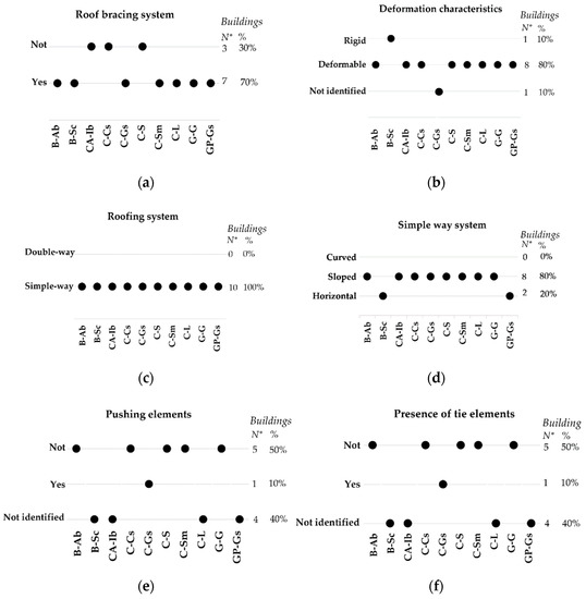
Figure 14.
Section 1B CARTIS-Building. Roof: (a) Roof bracing system; (b) Deformation characteristics; (c) Roofing system; (d) Shape of the roof; (e) Pushing elements; (f) Presence of tie elements.
Figure 14b shows the deformation characteristics of the roofing structure. In particular, eight buildings out of nine (89%) have a deformable system, and one building out of nine (11%) has a rigid system; for a building these data were not given. Figure 14c,d shows the type of roofing system: all the buildings (100%) have a simple-way system, two out of 10 are horizontal (20%), and eight out of 10 (80%) are sloped. Figure 14e,f shows the presence of pushing elements and their possible combination with tie elements. Data are not given for four buildings, for the remaining six buildings, one building (10%) has pushing elements but it has tie beams, five buildings, 50%, do not have pushing elements therefore do not have tie elements.
Closing Elements
Figure 15a shows the closing elements for each case study. In particular, all the buildings analyzed have “light elements”.
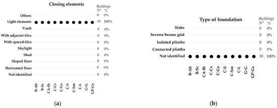
Figure 15.
Section 1B CARTIS-Building. (a) Closing elements; (b) Foundation.
Foundation
The section related to foundations allows to identify the type of foundations and the survey method. In fact, it is generally difficult to inspect the foundation structures of existing buildings.
For all the analyzed buildings, it was not identified (Figure 15b).
4.5. Section 2A CARTIS-Building: Description of the Building
The English version of the Section 2A is presented in Figure 16.
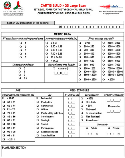
Figure 16.
Section 2A CARTIS-Building: Description of the building (English version [19]).
Metric Data
Figure 17a shows the number of total floors including the underground floors for each case study. Since there are no underground floors in any building analyzed, the number of floors shown in the figure corresponds to the number of floors above ground. In particular, nine out of 10 buildings (90%) are single-story and one out of 10 buildings (10%) has two stories.
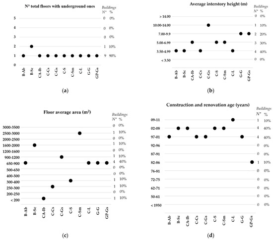
Figure 17.
Section 2A CARTIS-Building. Metric data: (a) Number of floors including the underground ones; (b) Average inter-story height; (c) Floor average area; (d) Construction and renovation age.
Figure 17b shows the average inter-story height for each case study, which for single-story buildings can be assumed to be the total height of the buildings, as well as to the maximum height of the column. In particular, the height ranges between 3.5 and 4.99 m for four out of 10 buildings (40%), between 5 and 6.99 m for three out of 10 buildings (30%), between 7 and 9.99m for two out of 10 buildings (20%); and between 10 and 14 m for one building out of 10 (10%).
Figure 17c shows the floor average area of the buildings for each case study. In particular, the area is less than 200 m2 for one out of 10 buildings (10%); it ranges between 250 and 300 m2 for one out of 10 buildings (10%), between 300 and 400 m2 for one out of 10 buildings (10%), between 650 and 900 m2 for four out of 10 buildings (40%), between 900 and 1200 m2 for one out of 10 buildings (10%), and between 2500 and 3000 m2 for one out of 10 buildings (10%).
Age
The date of construction and renovation of the buildings is useful to identify the technical standard for buildings used for the design, as well as the technological evolution of the structure.
Figure 17d shows the construction age for each case study. In particular, four out of 10 buildings (40%) were built in a period between 1997 and 2001, four out of 10 buildings (40%) between 2002 and 2008, one building out of 10 (10%) in 1986, and one building out of 10 (10%) in 2011. It can be deduced that the case studies are part of “modern age” buildings.
Use
Figure 18a shows the use of the buildings specified for each case study. In particular, four out of 10 buildings (40%) host public utility activities (schools), one out of 10 buildings (10%) is a sports facility, two out of 10 buildings (20%) are storehouses, two out of 10 buildings (20%) are supermarkets, and ones out of 10 building (10%) hosts productive activities (industry). Furthermore, the percentage of use, for all buildings, is greater than 65%; however, it is not possible to define the number of occupants and the maximum number of people inside the building.
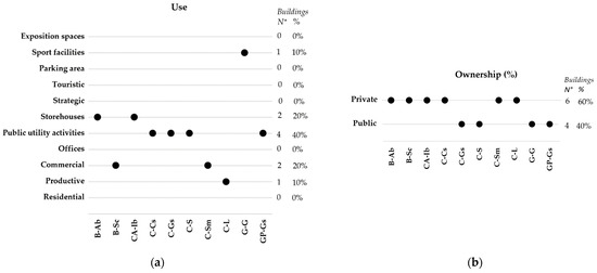
Figure 18.
Section 2A CARTIS-Building. Use–Exposure: (a) Use; (b) Ownership.
Ownership
Figure 18b shows the ownership of the building, if it is public or private, for each case study. In particular, six out of 10 buildings (60%) are private properties, and four out of 10 buildings (40%) are public properties.
4.6. Section 2B CARTIS-Building: Presence of Blocks Added to the Main Structure
The English version of the Section 2B is presented in Figure 19.
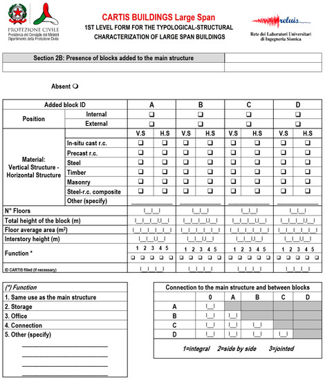
Figure 19.
Section 2B CARTIS-Building: Presence of blocks added to the main structure (English version [19]).
Added Block ID
The section is divided into four parts, each one corresponding to an added block: A, B, C, and D (Figure 20). With reference to the analyzed sample, four out of 10 buildings (40%) have one added block. Figure 20a shows the position of the block as respect to the main structure. In particular, for three buildings out of four (75%) the block is external to the main structure; for one building out of four (25%), the block is internal.

Figure 20.
Section 2B CARTIS-Building. Added block ID: (a) Position; (b) Function.
There is no information about the block technology and metric data.
Function
Figure 20b shows the function of the added block, specified for each case study. In particular, in all cases, all the buildings (100%) have the same function as the construction to which they are added.
4.7. Section 2C CARTIS-Building: Type of Connections, Panels, Special Loads, Other Non-Structural Elements
The English version of Section 2C is presented in Figure 21.
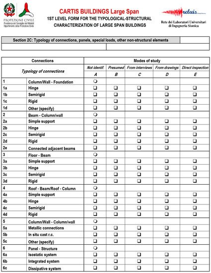
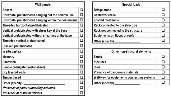
Figure 21.
Section 2C CARTIS-Building: Typology of connections, panels, special loads, other non-structural elements (English version [19]).
Connections
Connections are divided into six categories referring to the connected structural elements: column/wall to foundation, beam to column/wall, floor to beam, roof/beam to roof/column, column/wall to column/wall, and panel to structure. For each type, the method of investigation is indicated, such as how the information was achieved (not identified, presumed, from interviews, form drawings, or direct inspection), as well as the type of constraint expressed by the connection (hinge, semirigid, or rigid, Figure 22).
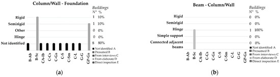
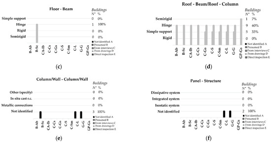
Figure 22.
Section 2C CARTIS-Building. Connections: (a) Column/wall to foundation; (b) Beam to column/wall; (c) Floor to beam; (d) Roof to beam/roof to column; (e) Column/wall to column/wall; (f) Panel to structure.
For the constructions analyzed, most of the information is related to the connections between roofing elements and between these last ones and the vertical structural system. In particular, for the “column/wall to foundation” connections (Figure 22a), for eight out of 10 buildings (80%), it was not possible to identify the type of connection, one out of 10 buildings (1%) has a rigid connection, and one out of 10 buildings (1%) has a semirigid connection; for the “beam to column/wall” (Figure 22b) and “floor to beam” (Figure 22c) connections, data are available for only one building (for the others it has not been detected), which has a hinge-type connection; for the “roof to beam/roof to column” connections (Figure 22e), nine out of 10 buildings (90%) have hinge-type connections, and among them five buildings (50%) also have simple supports; 1 out of 10 buildings (10%) have semirigid connections. For the “column/wall to column/wall” connections, data were only found for three out of 10 buildings, for which the type of connection was not identified (Figure 22f); for the “panel-structure” connections, data were found only for two out of 10 buildings, in which the type of connection was not identified (Figure 22g).
4.8. Section 3D CARTIS-Districts: Characterization of Timber Type
The English version of Section 3D is presented in Figure 6.
Type of Bracing System
For the analyzed cases, data collected mainly concern the roof bracing systems (Figure 23a) being available only for six out of 10 buildings. In particular, three out of six buildings (50%) have steel “X braces”, two out of six buildings (33%) have a system with a single timber diagonal, and one building out of six (17%) has steel “V braces”. Definitely, four out of six buildings (67%) have steel braces, and two out of six buildings (33%) have timber braces.
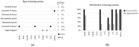
Figure 23.
Section 3D CARTIS-Districts. Characterization of timber type: (a) Type and (b) Distribution of bracing systems.
Figure 23b shows the distribution of the bracing systems in the longitudinal and transverse directions for each of the six buildings. In particular, in the transverse direction, five out of six buildings (83%) have braces on 100% of the length and one out of six buildings (17%) has braces on 60% of the length; in the longitudinal direction, one out of six buildings (17%) has braces on 100% of the length, one out of six buildings (17%) has braces on 80% of the length, one out of six buildings (17%) has braces on 70% of the length, and three out of six buildings (50%) have braces on 30% of the length.
Type of Connection
In all analyzed cases (100%), connections are made with bolted steel connectors (Figure 24).
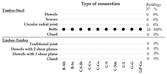
Figure 24.
Section 3D CARTIS-Districts. Characterization of timber type: Type of connections.
4.9. Section 3 CARTIS-Building: Other Information
The English version of the Section 3 is presented in Figure 25.
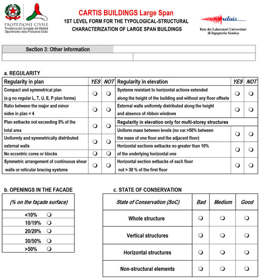
Figure 25.
Section 3 CARTIS-Building: Other information (English version [19]).
Regularity
The regularity in plan and in elevation are shown in Figure 26 for each case study. With regard to the regularity in plan, all buildings have a compact and symmetrical plan, as well as the ratio between the major and minor sides in plan that is lower than four; six out of 10 buildings (60%) have in plan setbacks that do not exceed 5% of the total area, and for four buildings data are not detected; all buildings have uniformly and symmetrically distributed external walls; seven out of 10 buildings (70%) do not have eccentric cores and blocks and three out of 10 buildings (30%) have eccentric blocks; seven out of 10 buildings (70%) have symmetrical arrangement of continuous shear walls or reticular bracing systems, and for three buildings data are not detected. Regarding the regularity in elevation, nine out of 10 buildings (90%) have systems resistant to horizontal actions extended along the height of the building and do not have floor offsets; one building out of 10 (10%) does not meet this requirement; five out of 10 buildings (50%) have external walls uniformly distributed along the height and do not have ribbon windows, and for five buildings data are not detected.
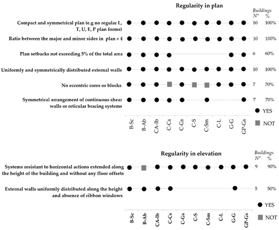
Figure 26.
Section 3 CARTIS-Building. Other information: Regularity in plan and in elevation.
Facade Openings
Figure 27 shows the percentages of the facade openings, specified for each case study. In particular, in all cases, five out of 10 buildings (50%) have a percentage of facade openings between 10 and 19% of the total facade surface, two out of 10 buildings (20%) have a percentage less than 10%, and for three buildings data are not recorded.
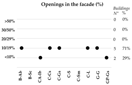
Figure 27.
Section 3 CARTIS-Building. Other information: Openings in the facade.
State of Conservation
The state of conservation can be assessed as bad, medium, or good, with reference to the whole structure, the vertical structural system, the horizontal structural system, and the non-structural elements.
The state of conservation is specified in Figure 28 for each case study. It is worth noticing that the evaluation has been carried out simply by phone interviews to the buildings’ owners or managers, asking them to describe the overall state of conservation of vertical and horizontal structures, as well as of the non-structural elements. The state of conservation has been evaluated as good, medium, or bad, and if there is no notice of damage, or notices of damage not compromising the functionality of the buildings, or notices of damages compromising the functionality of the building, were given, respectively. In particular, all buildings have a good state of conservation of the structures. As for non-structural elements, nine out of 10 buildings (90%) have a good state of conservation and one out of 10 buildings (10%), has a medium state of conservation.
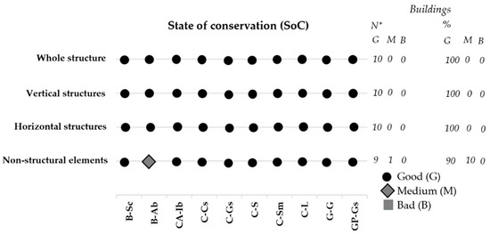
Figure 28.
Section 3 CARTIS-Building. Other information: State of Conservation (SoC).
4.10. Analysis of the Results
The data processed is represented below in a synoptic framework (Table 2, Table 3, Table 4, Table 5, Table 6, Table 7, Table 8, Table 9, Table 10, Table 11, Table 12, Table 13 and Table 14) for each section of the draft CARTIS form. This framework can be updated and enriched by adding further cases.
Table 2.
Section 0 CARTIS-Building. Case studies characterization: Identification of municipality and building—Synoptic panel.
Table 3.
Section 1A CARTIS-Building. Case studies characterization: Identification of the building constructive technology—Synoptic panel.
Table 4.
Section 1B CARTIS-Building. Case studies characterization: Identification of the building typology—Synoptic panel.
Table 5.
Section 1B CARTIS-Building. Case studies characterization: 1. Vertical structural system and relationship with intermediate floors—Synoptic panel.
Table 6.
Section 1B CARTIS-Building. Case studies characterization: 2. Roof: Simple way system: main member typology—Synoptic panel.
Table 7.
Section 1B CARTIS-Building. Case studies characterization: 3. Foundation—Synoptic panel.
Table 8.
Section 2 CARTIS-Building. Case studies characterization: Metric data—Synoptic panel.
Table 9.
Section 2 CARTIS-Building. Case studies characterization: Age—Synoptic panel.
Table 10.
Section 2 CARTIS-Building. Case studies characterization: Use—Synoptic panel.
Table 11.
Section 2B CARTIS-Building. Case studies characterization: Presence of blocks added to the main structure—Synoptic panel.
Table 12.
Section 2C CARTIS-Building. Case studies characterization: Typology of connections, panels, special loads, and other non-structural elements—Synoptic panel.
Table 13.
3D CARTIS-Building section. Case studies characterization: Characterization of timber type—Synoptic panel.
Table 14.
3D 3G CARTIS-Building section. Case studies characterization: Other information—Synoptic panel.
5. Conclusive Remarks and Further Development
The preservation of built heritage is a major issue in seismic zones. Constructions must be equipped with technologies aimed both at the conservation and the improvement of the overall structural behavior, in order to reduce the vulnerabilities and therefore the seismic risk.
The CARTIS form is set up both for the census of structural types of existing constructions and for the application of quick levels methods for the existing buildings seismic vulnerability assessment. It is intended to be related to all types of structures (reinforced concrete, prefabricated, steel, masonry, and timber).
In this paper, the focus is on timber large span structures. In particular, starting from a study [10] on a sample of 101 timber constructions, supplied by Rubner Holzbau, the CARTIS form has been used for the description of 10 buildings with timber large span structures. Each section has been filled; thus, graphs and statistics about the building’s features have been elaborated in order to have an overview of the common structural typology. At the end, the study’s results are provided in synoptic tables.
The main aspects are synthesized in the following. Buildings are located in the same region (Emilia Romagna), in a seismic zone 3 (with earthquake PGA between 0.05 g m/s² and 0.15 g m/s²). Most of them were built between 1997 and 2001 (40%) and between 2002 and 2008 (40%), as mainly intended for civil activities (60%). They are characterized by a single story (90%); having only one nave (80%); being 10–20 m long (70%); a variable number of bays from 9 (10%) to 6 (30%), 5 (20%), 4 (30%), and 3 (10%), 4–6 m long (70%); and a column height less than 6 m (60%). The vertical structure is made of in situ cast r.c. for 21% of the buildings and in precast r.c. for 11% of the buildings; the vertical seismic-resistant systems for 45% of buildings are isolated columns, while for 18% they are moment resisting frames, and for 36% uncoupled walls. The horizontal seismic-resistant system is, for the most part, characterized by concentric X-bracing system (70%), in plan deformable floor (80%) and sloped roof (80%) with a simple way system (100%). All connections of the timber roofs are timber–steel type with bolts, realizing a hinge constraint, except for the column/wall–foundation connection, that is rigid, and for column/wall–column/wall and panel-structure connections that are not identified. From the analysis carried out, all the buildings show a good state of conservation of the vertical and horizontal structures, and only 10% of buildings have a medium state of conservation of the non-structural elements.
The CARTIS form for large span structures is currently a preliminary draft under evaluation. In particular, the form related to timber large span structures is a recent novelty, proving the significant role that timber is playing in the national built heritage, even of public importance. Therefore, it represents a key starting point, which has to be improved based on the peculiarities of such constructions, related to the typical structural types and static schemes, element types, stiffening systems, both vertical and horizontal ones, seismic resistant systems, and connections.
The statistic elaboration has been set up and applied on 10 buildings only; however, the base tools have been defined, so that they can be easily further applied including any possible study case, in order that the analysis could be more robust and representative of the built heritage of large span timber structures.
A future step is the digitalization of the database, which is one of the ongoing tasks of the ReLUIS WP2. The CARTIS forms data can be already transferred in corresponding electronic sheets. Further development is the setup of automatic statistical elaboration, linking the database to the percentage calculation sheets and graphs, updating case by case all the data, which also converge in the synoptic tables.
Nevertheless, the database can be also used to acquire the data for the vulnerability assessment of built heritage against the earthquake, applying the quick level methods based on the evaluation of the vulnerability elements of the constructions. Additionally, a digital procedure can be implemented for this application.
Not least, considering also the sections related to the state of conservation, which could be further developed, for catching all the aspects of degradation in the constructions, data acquired through the CARTIS form could be also used to select the most appropriate solutions of maintenance and renovation.
Work is in progress to reach these objectives.
Author Contributions
Conceptualization, B.F.; methodology, B.F., M.P. and R.L.; software, G.I.; validation, B.F., M.P. and R.L.; formal analysis, G.I., A.G.; investigation, G.I., A.G.; resources, A.G., M.P.; data curation, B.F., G.I., A.G., E.F., A.B., R.L., M.P.; writing—original draft preparation, B.F., G.I.; writing—review and editing, B.F.; visualization, B.F., G.I.; supervision, B.F., E.F., A.B., M.P.; project administration, B.F., M.P., R.L.; funding acquisition, M.P., R.L. All authors have read and agreed to the published version of the manuscript.
Funding
This research was funded by DPC/ReLUIS 2019/2021 and The APC was funded by DPC/ReLUIS 2019/2021.
Institutional Review Board Statement
Not applicable.
Informed Consent Statement
Not applicable.
Data Availability Statement
The data presented in this study are available on request from the corresponding author.
Acknowledgments
Authors acknowledge the Italian national project DPC/ReLUIS 2019/2021 (WP2: Inventory of existing building structural types—CARTIS, coordinator G. Zuccaro; Task 2.3.4: Vulnerability of Large Span structural typologies—coordinators R. Landolfo, M. Piazza) and the ERASMUS student Vincent Stevenet, from Polytech Clermont Ferrand, who provided a contribution in the statistical elaboration during his master thesis.
Conflicts of Interest
The authors declare no conflict of interest. The funders had no role in the design of the study; in the collection, analyses, or interpretation of data; in the writing of the manuscript, or in the decision to publish the results.
References
- GNDT. Seismic Risk of Public Buildings, Part I: Methodology; Tipografia Moderna: Bologna, Italy, 1993. (In Italian) [Google Scholar]
- FEMA P-154. Rapid Visual Screening of buildings for Potential Seismic Hazards: A Handbook, 3rd ed.; Applied Technology Council, FEMA: Washington, DC, USA, 2015.
- Mouroux, P.; Le Brun, B. Risk-Ue Project: An Advanced Approach to Earthquake Risk Scenarios with Application to Different European Towns. Assess. Manag. Earthq. Risk 2007, 2, 479–508. [Google Scholar] [CrossRef]
- Faggiano, B.; Formisano, A.; De Gregorio, D.; De Lucia, T.; Mazzolani, F.M.; Formisano, A. A Quick Level Methodology for the Volcanic Vulnerability Assessment of Buildings. Appl. Mech. Mater. 2011, 82, 639–644. [Google Scholar] [CrossRef]
- Mazzolani, F.M.; Faggiano, B.; Formisano, A.; De Gregorio, D.; Zuccaro, G.; Indirli, M.; Borg, R.P. Survey activity for the volcanic vulnerability assessment in the Vesuvian area: The ‘quick’ methodology and the survey form. In Proceedings of the COST Action C26 Final Conference “Urban Habitat Constructions under Catastrophic Events”, Naples, FL, USA, 16–18 September 2010; CRC Press, Taylor & Francis Group: London, UK, 2010; pp. 693–698. [Google Scholar]
- Baggio, C.; Bernardini, A.; Colozza, R.; Corazza, L.; Della Bella, M.; Di Pasquale, G.; Dolce, M.; Goretti, A.; Martinelli, A.; Orsini, G.; et al. Field Manual for Post-Earthquake Damage and Safety Assessment and Short-Term Countermeasures (Ae-DES); Pinto, A.V., Taucer, F., Eds.; EUR 22868 EN; Office for Official Publications of the European Communities: Luxembourg, 2007. [Google Scholar]
- Zuccaro, G.; Dolce, M.; De Gregorio, D.; Speranza, E.; Moroni, C. La scheda CARTIS per la caratterizzazione tipologico-strutturale dei comparti urbani costituiti da edifici ordinari. Valutazione dell’esposizione in analisi di rischio sismico (The CARTIS form for the typological-structural characterization of urban areas with ordinary buildings. Exposure assessment in seismic risk analysis). In Proceedings of the 34th National Conference GNGTS (Gruppo Nazionale di Geofisica della Terra Solida), Trieste, Italy, 17–19 November 2015; pp. 281–287. (In Italian). [Google Scholar]
- Dietsch, P. Robustness of large-span timber roof structures—Structural aspects. Eng. Struct. 2011, 33, 3106–3112. [Google Scholar] [CrossRef]
- Munch-Andersen, J.; Dietsch, P. Robustness of large-span timber roof structures—Two examples. Eng. Struct. 2011, 33, 3113–3117. [Google Scholar] [CrossRef]
- Dietsch, P.; Gamper, A.; Merk, M.; Winter, S. Monitoring building climate and timber moisture gradient in large-span timber structures. J. Civ. Struct. Health Monit. 2015, 5, 153–165. [Google Scholar] [CrossRef]
- Crocetti, R. Large-Span Timber Structures. In Proceedings of the World Congress on Civil, Prague, Czech Republic, 30–31 March 2016. Paper No. ICSENM 124. [Google Scholar] [CrossRef]
- Dietsch, P.; Winter, S. Structural failure in large-span timber structures: A comprehensive analysis of 230 cases. Struct. Saf. 2018, 71, 41–46. [Google Scholar] [CrossRef]
- Masse, A.; Faggiano, B.; Fournely, E.; Iovane, G.; Mazzolani, F.M.; Bouchaïr, A. On the seismic vulnerability assessment of timber and steel large-span structures. In Proceedings of the 2018 World Conference on Timber Engineering (WCTE2018), Seoul, Korea, 20–23 August 2018. [Google Scholar]
- Gaspari, A.; Giongo, I.; Modena, R.; Bertacco, D.; Piazza, M. Seismic resilience of timber structures during the earthquake events of the past decade in Italy. In Proceedings of the 2018 World Conference on Timber Engineering (WCTE2018), Seoul, Korea, 20–23 August 2018. [Google Scholar]
- Branco, J.; Neves, L.C. Robustness of timber structures in seismic areas. Eng. Struct. 2011, 33, 3099–3105. [Google Scholar] [CrossRef]
- Stepinac, M.; Rajčić, V.; Barbalić, J. Inspection and condition assessment of existing timber structures. J. Croat. Assoc. Civ. Eng. 2017, 69, 861–873. [Google Scholar] [CrossRef]
- Serafini, A.; Riggio, M.; González-Longo, C. A database model for the analysis and assessment of historic timber roof structures. Int. Wood Prod. J. 2016, 8, 3–8. [Google Scholar] [CrossRef]
- Riggio, M.; D’Ayala, D.; Parisi, M.; Tardini, C. Assessment of heritage timber structures: Review of standards, guidelines and procedures. J. Cult. Herit. 2018, 31, 220–235. [Google Scholar] [CrossRef]
- “CARTIS Grandi Luci-Scheda di 1° Livello per la Caratterizzazione Tipologico-Strutturale di Edifici a Grandi Luci” (CARTIS Large Span—1st Level Form for the Typological-Structural Characterization for Large Span Buildings); ReLUIS 2019/2021, WP2 Inventory of Existing Building Structural Types-CARTIS. Task 2.3.4. Vulnerability of Large Span Structural Typologies; DPC: Rome, Italy. (In Italian)
- Dipartimento della Protezione Civile. Available online: www.protezionecivile.gov.it/attivita-rischi/rischio-sismico/attivita/classificazione-sismica (accessed on 1 January 2021).
- NTC2018: Technical Standards for Construction. D.M. 17.01.18-“Norme tecniche per le costruzioni”. (In Italian)
- Dolce, M.; Pizza, A.G.; Papa, F.; Ferlito, R.; Biondini, F.; Magliulo, G.; Pavese, A.; Bolognini, D.; Bellotti, D.; Achilli, T.; et al. Manuale per la Compilazione Della Scheda di Valutazione di Danno e Agibilità Post-Sisma per Edifici a Struttura Prefabbricata o di Grande Luce (GL-AeDES)” (Manual for the Compilation of the Post-Earthquake Damage and Usability Assessment Form for Prefabricated or Large Span Buildings, GL-AeDES); Department of Civil Protection: Rome, Italy, 2014. (In Italian) [Google Scholar]


Publisher’s Note: MDPI stays neutral with regard to jurisdictional claims in published maps and institutional affiliations. |
© 2021 by the authors. Licensee MDPI, Basel, Switzerland. This article is an open access article distributed under the terms and conditions of the Creative Commons Attribution (CC BY) license (http://creativecommons.org/licenses/by/4.0/).