Abstract
The steel Modular Building Systems (MBSs) that have been influenced by the Light-gauge Steel Frame (LSF) techniques have become a prominent culture in the industry. However, the detrimental behaviour of steel structural components at high temperatures has elevated the risk of fatal accidents in the event of a fire. Although several research investigations have addressed the fire performance of steel modular wall systems, the behaviour of modular floor systems has not been adequately addressed in the state of the art. Hence, to promote the fire safety and optimum design techniques in the modular construction industry by addressing the aforementioned research gap, this study investigated 48 conventional LSF and MBS floors for their structural and insulation Fire Resistance Levels using Finite Element Modelling (FEM) and Heat Transfer Analyses (HTA) techniques. Initially, full-scale experimental fire tests were modelled using FEM methods, and the validity of the techniques was verified prior to the analyses of parametric floor systems. Furthermore, the structural behaviour of the channel section joists in the elevated temperatures was studied, and hence a correlation was established to determine the critical steel temperature at the structural fire failure with respect to the applied Load Ratio (LR). An additional 12.5 mm thick plasterboard sheathing on single plasterboard sheathed floors resulted a 30 min improvement in structural and insulation FRLs. In addition, the modular floor systems demonstrated enhanced structural and insulation Fire Resistance Levels (FRLs) against the corresponding conventional LSF floor designs due to double LSF skin build-up. The incorporation of rockwool insulation and the increase in the insulation volume implied increased structural and fire performances. However, insulation material in the modular designs was more effective. The fire-rated conventional and modular LSF floor systems are expected to be practised in the construction industry to achieve required fire resistances with optimum material usage.
1. Introduction
1.1. Background
The most efficient method of investigating steel Modular Building Systems (MBSs) is the simultaneous analyses of both Light-gauge Steel Frame (LSF) systems and MBSs. LSF construction methods have been widely applied in various types of structures in the recent couple of decades. LSF systems made of lightweight, cold-formed steel structural elements are factory manufactured as wall and floor panels, which are transported to the construction site to assemble with the foundation to build structures. Thereafter, Mechanical, Electrical and Plumbing (MEP) are needed and the finishes can be completed on site. With the option of wall/floor panel pre-fabrication and mass-scale factory manufacturing, LSF constructions are associated with numerous advancements with respect to the long-established heavier construction technology. The elevated quality of walls/floors due to factory manufacturing, construction waste reduction, lower demand for skilled labour at the construction site, potential recyclability options and more importantly huge cost and time savings can be named as few such advancements related to the LSF technique. These interesting features pushed the construction industry to adopt more pre-fabrication options and further advanced techniques such as MBSs. In MBSs, volumetric modular units are constructed at the pre-fabrication stage, hence MEP and internal finishing also could be implemented in the controlled factory environment. Such volumetric modular units are then transported to the construction site and assembled with the foundation and structural core, leaving much less work left to be carried out on site. Therefore, all the advantages achieved with LSF constructions are preserved and even enhanced with the MBSs.
As for the build-up and design of LSF and steel modular wall/floor panels, both construction techniques comprise lightweight steel structural frame elements (mostly cold-formed steel), wall/floorboards and different insulation materials. Therefore, similar numerical analyses methods could be adopted for the fie performance investigations of LSF systems and MBSs. However, since modular construction involves volumetric units being assembled, a typical floor separation of a multi-story structure consists of the ceiling panel of the volumetric unit below and the floor panel of the volumetric unit above. Therefore, when the fire resistance of modular floor systems is concerned, the integrity of both ceiling and floor panels must be addressed. In addition, it is also necessary to mention that the flames are propagating in the upward direction, and it is vital for a floor panel to demonstrate higher fire resistance when fire is applied from the bottom side of the floor panel. Fire performance investigations of LSF and steel MBS floor systems conducted by previous researchers [1,2,3,4] provide good evidence for the necessity of critical consideration when fire is applied from the bottom side of the floor panel. Typical constructions of an LSF floor system and a modular floor system are presented in Figure 1.
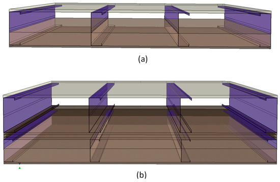
Figure 1.
Construction of floor Systems: (a): conventional LSF floor and (b) modular LSF floor.
LSF and MBS structures are associated with a range of appreciable features for their lightweight and pre-fabrication options, yet the fire spread and possibility of fatal accidents in a fire event can never be undermined. In fact, traditional heavier constructions are more resilient in fires when compared against lightweight construction methods such as LSF and MBS practices. Comparatively low heat capacities and use of combustible thermal insulation are the main driving forces that adverse the fire spread of LSF and MBS constructions in a fire event. Moreover, as lightweight steel members are the structural members of both these constructions, the detrimental behaviour of steel worsens the fire safety of LSF and steel modular built environments, making those susceptible for fatal fire accidents.
At the same time, MBS applications are only gaining popularity and substituting other construction methods by addressing many challenges in the construction industry. However, there exists quite a limited amount of research on either LSF or steel modular floor systems against fire performance, such as Gatheeshgar et al. [2] and Steau et al. [4,5,6], compared to the widespread research studies conducted on the LSF and steel modular wall systems against fire performance and thermal transmittance, such as Chen et al. [7,8,9], Santos et al. [10], Perera et al. [11,12,13,14,15], and Rusthi et al. [16,17], where the wall board options, stud geometry options, location of insulation material, optimisation of cavity Insulation Ratio for better fire and energy ratings and the performance of innovative wall system designs have been comprehensively analysed. Increasing popularity and applications of MBSs, the susceptible nature of MBSs to fatal accidents and the absence of adequate research and investigation on LSF and modular floor systems in fire have been identified as the research gap for the current study. Hence, in this paper, commonly used LSF and steel modular floor systems were investigated for their structural and insulation fire resilience using numerical methods. Single/double gypsum board sheathing options and location and ratio of insulation were studied in the parametric study with the objective of understanding the optimum design configurations. The establishment of research knowledge on the fire ratings of LSF and steel modular floors in present study will provide the building designers the ability to choose floor panel designs with adequate/required fire ratings at the optimum material usage.
1.2. Research Focus
To investigate the fire performance of LSF and steel modular floor panel designs, Finite Element Modelling (FEM) numerical methods were explicitly used with ABAQUS CAE, a commercially available computational package. The 12.5 mm thick ceiling boards in single- to double-sheathing options were considered in conventional and modular LSF floor panel designs. At the same time, application of partial, full and no cavity insulations were investigated, where the cavity Insulation Ratio (IR) was changed between 0, 0.2, 0.4, 0.6, 0.8 and 1.0.
2. Determination of Fire Resistance Level
2.1. Standard Practice
The established method of rating the FRL of building elements is based on Eurocode 3: Part 1–2 [18]. Although the fire curve can be determined in accordance with the parametric fire scenarios, the standard practice involves following the ‘ISO 834’ standard fire curve to specify the fire rating of building components. This convention is more convenient and practical, where the building elements can be directly compared for their fire performances. As the standard fire curve temperatures are experimentally or numerically applied on the exposed side surface of the building element, time to structural, integrity and insulation failures are to be determined in order to evaluate the fire resistance of that element. The structural FRL is the time of fire exposure until the element is structurally incapable of supporting the loads applied on it. Meanwhile, the integrity failure is referred to as when the building component loses its ability to resist infiltration of hot gases and flames from one side to the other through itself. The insulation FRL is specified based on the temperature rise on the unexposed side of the building component. As per the Eurocodes, when either the average or maximum values of unexposed surface temperature rises reach beyond 140 °C or 180 °C, respectively, the insulation fire resistance is specified. If a 20 °C ambient temperature is considered, these thresholds will be 160 °C and 200 °C for the average and maximum unexposed temperatures.
In this study, a series of LSF and steel modular floor panels were numerically analysed for their FRLs. Firstly, the well-validated FEM methods described in the next section were adopted to re-create the floor panels. Heat Transfer Analyses (HTA) were conducted on each floor panel applying standard fire temperatures from the bottom side (ceiling side) of the floor systems. HTA results were produced, which contained temperature variation through thickness of the floor systems for a 240 min period. The temperature variations in the steel joists were analysed for the determination of structural FRL, while the unexposed side temperature variations were analysed for the insulation FRL. However, it should be stated that determination of integrity failure using presently available numerical techniques has not been proven to be effective. At any rate, the floor panel designs investigated in the study include gypsum boards on the fire side, and with the evidence of previous experimental investigations [19,20] the structural fire failure can be expected to be more critical than the integrity fire failure.
2.2. Structural Failure of Channel Section Joists at Elevated Temperatures
Most of the steel MBS and LSF floor systems comprise channel section steel studs as the structural load carrying elements. Hence, the structural behaviour of channel section steel studs with exposure to elevated temperatures has been investigated in previous research studies [3,21], from which a correlation between the LR values and the average joist temperatures were developed in the current study.
In the event of a fire, the temperatures of the exposed surfaces of the building can even rise beyond 1100 °C. Based on the fire protection measures and heat transfer characteristics of the floor panel, the steel joist temperature will also rise as the exposed temperature rises. In this scenario, the steel section will be subjected to differential temperature distribution since the fire load is generally applied on one side of the floor panel. The relative hot and cold flanges (HF and CF) are the bottom and top flanges of the joist, respectively. The joists as the structural elements of the floor panels are designed as beam members to support the floor loads in bending. Here, the bottom flange (which is also the HF) is applied with tension while the top flange (CF) is applied with compressive stresses. As the temperature of the joist rises, the temperatures of the bottom flange will always be the maximum. Therefore, the material strength of the bottom flange degrades at higher rates than that of the top flange. When the bottom flange (HF) reaches a certain temperature, the bottom-most elements of the HF will lose the strength beyond the required resistance. At this event, the effective cross-section will be reduced, and the neutral axis will shift upward to resist the applied bending stresses. At the next instance, the elements of the adjacent layer of the bottom flange will also reach the critical temperature and subsequently become ineffective, contributing to further upward shift of the neutral axis of the steel joist. This action will continue if the fire temperature continues to rise, until the steel joist experiences the ultimate structural failure when further stabilising of the neutral axis to resist the applied bending moment is not possible. Although the calculation of the structural failure instance of the steel joist appears to be a little complex, the experimental and FE numerical results available for a range of channel section steel joist structural fire failures were used to develop an empirical relationship between the applied LR and the average steel joist temperature at the structural failure, as presented in Figure 2. In fact, 324 structural fire failure results of channel section joists were analysed to develop this correlation.
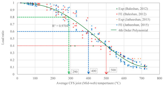
Figure 2.
LR versus critical steel temperature of channel section joists at the structural failure of LSF floors [3,21].
The established relationship on the structural failure of steel joists in Figure 2 can be used along with the HTA results of steel joists to produce the time to the structural failure of the LSF and steel MBS floors in fire events. The HTA of a floor panel under consideration can be carried out to derive the temperature variations in the steel joists at both HF and CF with respect to the elapsed time. The correlation between LR and the average temperature graph can be referenced to estimate the critical steel temperature related to the structural failure at a required LR, as presented in Table 1. Since HF and CF temperature variations are known, the average of those two can be analysed against the estimated critical steel temperature. Hence, the time related to that critical steel temperature could be simply predicted from the HTA results, which can be produced as the structural FRL of the floor panel.

Table 1.
Critical average temperatures for structural fire failure of channel section joists at different LRs.
However, limitations exist when this correlation is used to predict critical steel temperatures beyond 0.4 LR. Hence, it is advised to adopt this simplified method to estimate the structural FRL for higher LR values where the steel temperatures are less than 400 °C [2].
3. Numerical Analyses
Numerical analyses using FEM techniques were adopted to investigate the structural and insulation fire ratings of the conventional LSF and steel modular floor systems considered in the study scope. To derive the time variant temperature profiles through the floor thickness, HTA were necessary on the developed FEMs using ABAQUS CAE application. For reliable HTA results, the validity of the inbuilt HTA models, appropriate thermal properties of building material throughout the temperature envelope of the fire curve and the accurate FEM methods to define constraints, interactions and boundary conditions are essential. In fact, the modelling of fire test using FEM techniques involves a range of variables that influence the reliability of the HTA results; hence, several full-scale fire experiments on similar LSF systems are validated and presented in this section for the confidence application of the techniques and results.
3.1. Thermal Properties of Wall Specimen Materials
When conducting HTA, conduction, convection and radiation mode heat transfer mechanisms must be recreated. Thermal properties of building materials determine the conduction mode heat transfer. Density, thermal conductivity and the specific heat are identified as the thermal properties. Generally, these three properties are constants in the ambient temperature. However, when it comes to the fire performance of floor systems, the building materials are subjected to temperatures ranging from 20 °C to more than 1100 °C, and hence, the thermal properties are found to be varying significantly, causing dramatic variations in the heat transfer characteristics as well. Previous experimental and numerical research studies [17,22] on fire tests of building components have adopted realistic thermal properties of gypsum board, rockwool insulation and plywood board, as presented in Table 2. The well-established thermal properties of steel presented in Eurocode 3 [18] have also been extracted for the numerical simulation in the present study.
Table 2.
Thermal properties of the materials involved in the numerical study.
In this study, numerical studies of only HTA were conducted on the developed FEMs. Hence, the mechanical properties of the building materials were not considered in the FEM analyses phase, but the elevated temperature thermal properties described in this section were used to simulate the heat transfer mechanisms in the fire state. However, an alternative simplified approach described under Section 2.2 was used to evaluate the structural failure incident of the steel joists in a fire.
3.2. FEM Details
The FE techniques adopted in the study to simulate fire exposure incidents of floor systems are presented in detail in this section. ABAQUS CAE, the commercially available explicit software package, was used for the HTA on FEMs after careful review of the HTA models defined inside the application [23]. The objective was to simulate standard fire exposure of floor systems recreating similar constraints, interactions, boundary conditions and heat transfer mechanisms so that time variant temperature profiles at the steel joists and on the unexposed surface of the floor panel could be derived. Specifically, numerical simulation of the equivalent full-scale experimental set-up of LSF and steel modular floor systems was intended to obtain realistic fire test results, saving huge costs and time. Firstly, a series of experimental results were used to validate the thermal properties and FEM methods. Afterward, the same techniques were used to simulate the fire exposure of parametric floor systems.
To develop the FEM of a floor panel, all building components are to be modelled in the correct shapes which are referred to as ‘parts’ in ABAQUS CAE. When the parts of steel joists, gypsum boards, plywood boards and insulation sections were modelled, correct material properties must be assigned and meshed into finite elements. Thermal properties presented in Table 2 were fed to the model, creating required material sections, and those sections were then assigned to the building component parts. Discretisation of parts into finite elements must be associated with accurate element types, shapes and size in order to produce reliable HTA results. The global mesh density of 10 mm was chosen, while the density in the through thickness direction was maintained at 2 mm, since that is the dominant direction of heat transfer. The steel joists in the parametric floor systems are quite slender, hence three finite elements were maintained in the thickness of the joist cross-sections. These mech densities were adopted based on previous sensitivity analyses [17,24] and with the validation studies conducted in the current study. A presentation of the FEM of the modular floor system with single plasterboard sheathing and a 90 mm rockwool insulation option is in Figure 3. Hexagonal-shaped finite elements were assigned in order to obtain a consistent mesh for all parts. Next, DC3D8 heat transfer brick elements were chosen as the type of finite elements to enable element to element conduction mode heat transfer.
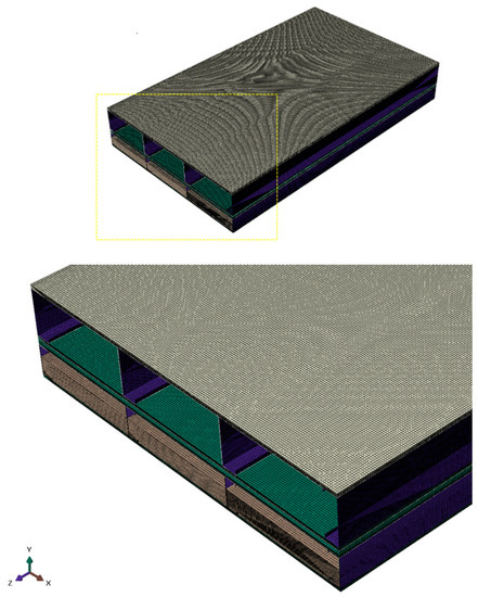
Figure 3.
FEM of M_SP_90RW floor system.
However, to facilitate conduction mode heat transfer between adjacent elements belonging to two parts in contact, it is required to apply tie constraints. Hence, between all contact surface pairs, tie constraints were applied. Subsequently, convection and radiation heat transfers on the surfaces were enabled, defining appropriate interactions. The convection film coefficient used on exposed and unexposed surfaces was set at and , respectively. The flow of air currents inside the closed cavities of the floor systems are quite restricted; hence, the convection mode heat transfer inside the cavity regions could be reasonable neglected. Then, the radiation mode heat transfer was defined on all exposed, unexposed and cavity surfaces, where the relative emissivity coefficient was set at 0.9. When the FEM of the floor system is generated up to this stage, then it is necessary to create the fire load on the exposed surface and run the analyses for the required time. Two steps were used, where the initial step is the steady-state condition when the floor panel is at room temperature. The initial step was followed by a transient heat transfer step, which was used to define the fire temperatures on the exposed surface of the floor system as a temperature boundary condition. The ISO 834 standard fire curve is expressed in Equation (1) for the fire temperature (°C), where t (min) is the time elapsed.
The present study defined with the time temperature values produced for the standard fire curve, and this curve was used to apply the temperature boundary condition on the fire side of the FEM. All interactions and boundary conditions on a typical modular floor system are illustrated in Figure 4.
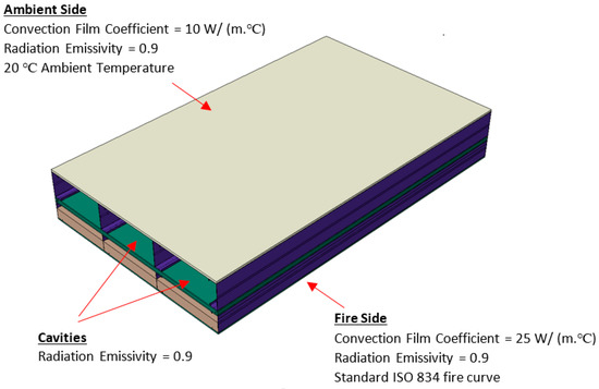
Figure 4.
Interactions and boundary conditions on FEM of M_SP_90RW floor system.
FEMs of the floor panels were developed in this procedure on which the HTA were performed, where necessary temperatures through floor thickness were derived. Fire side (FS), hot flange of the joist (HF), mid-web (MW), cold flange (CF) and ambient side (AS) temperature variations over 4 h of fire exposure were obtained for all floor systems analysed in the study.
It should be noted that with respect to the current industry practice, the floor systems studied in the current scope consist of cold-formed, lipped channel section joists that do not contain welded joints. The joist sections are generally connected to the floorboards with self-drilled screws at 100 to 400 mm spacing. With floor systems containing welded joints between structural frame elements, it is required to consider the behaviour of welded joints at high temperatures [25,26,27].
3.3. Validation of FEMs
As described at the beginning of the section, HTA of fire tests are related to an extensive number of variables and a considerable complexity is present. In that event, to ensure the reliability of the FEM approaches, validation of several experimental specimens was necessary. The full-scale fire tests on LSF floor systems conducted by Balachandren [21] and Jatheeshan [3] were validated using the numerical approaches descried above.
LSF floor panel designs experimentally studied under standard fire exposure were numerically modelled for further verification of the Fem methods on floor systems. The first LSF floor configuration comprises lipped channel section studs placed at centres and sandwiched between a thick plywood floorboard and two layers of thick gypsum boards. The standard fire temperatures were applied on the bottom side of the floor panel, where the gypsum board sheathed surface was fire-exposed. The floor panel was numerically modelled using ABAQUS CAE software, and the time–temperature profiles at FS, HF, CF and AS were produced following the HTA. The numerically derived time variant temperatures were compared against the experimentally obtained values as presented in Figure 5, where a good agreement was seen.
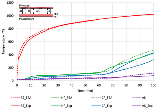
Figure 5.
FEA versus experimental temperatures of floor panel specimen—Test 1 [1].
The second test of the experimental series consisted of same stud section joists at centres and on either side of the floor panel two layers of thick gypsum board sheathing. Additionally, the floor comprised a rockwool cavity insulation with thickness. This floor system was also numerically simulated in this current study, as shown in Figure 6.
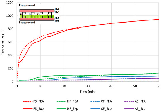
Figure 6.
FEA versus experimental temperatures of floor panel specimen—Tests 2 [1].
Considering both validation studies implemented in this current study, the presented thermal properties and adopted FEM methods were validated well against the reliable research experimental investigations that have taken place in various parts of the world. Hence, the presented thermal properties and FEM techniques could be confidently used for further investigations of fire tests addressing the research scopes, as necessary.
3.4. Limitations of the Study
When gypsum board is subjected to fire temperatures, the board material will undergo shrinkage, and hence, moisture movement and board cracking will be induced. This specific behaviour is referred to as the ablation effect, which could not be reliably simulated with only numerical means such as FEM techniques. Therefore, integrity criterion FRL was not investigated in the current study scope. However, the measured thermal properties were modified to apparent values to simulate the effect on heat transfer caused by ablation and moisture movement. This approach was followed by various researchers [17,28,29], and the reliability of HTA results obtained in this manner was established.
4. Parametric Study and FEA Results
The present study addressed a few variables related to commonly practised LSF and steel modular floor systems. A total of 48 parametric floor panels were investigated by developing their FEMs. Since channel section joists are being widely used as the structural elements in LSF and steel modular floor designs, all the floor system designs studied were based on two sizes of lipped channel section joists. The conventional floors only consist of a single LSF skin, where floor joists were 231 mm deep. The steel modular floor systems comprise two LSF skins, a floor panel and a ceiling panel. Though the weight on the floor is structurally supported by the floor panel joists alone, the ceiling panel is designed to support its own weight. The joists integrated in the floor panel LSF skin of the modular floor system contain 231 mm deep lipped channel section joists, while the ceiling panel LSF skin contains 150 mm deep joists. Since 231 mm deep joists are the structural elements bearing the loading on the floor panel in both conventional and steel modular LSF floors, the FRLs were studied in comparison to each other. All floor systems consisted of 12.5 mm thick gypsum plasterboard on the bottom side and an 18 mm thick plywood board on the top side of the floor. Since it is a common practice to use double plasterboard sheathing as an enhancement on fire performance, the floor systems included specimens with both single and double plasterboard sheathing options. Furthermore, the level of cavity insulation has a significant influence on the fire resistances of LSF constructions. Rockwool insulation material has proved to be a favourable insulation option for the fire rating and on the energy rating as well. At the same time, other good insulation options such as mineral wool and glass fibre inherit similar thermal properties, and no significant influence has been found when the cavity insulation type is changed between rockwool, glass fibre and mineral wool when the fire ratings of LSF constructions are concerned [12,17,28]. Therefore, only rockwool insulation material was used as the cavity insulation option. Further research and investigations on fire ratings of LSF constructions [12,30] have suggested that the location and amount of insulation material could influence both fire and energy ratings of the structures. Hence, rockwool insulation was incorporated in the conventional and modular LSF floor systems right next to the fire-exposed gypsum boards at different thicknesses from 0 to 150 mm in 30 mm steps. The considered variables in the present study scope are explained in Figure 7.
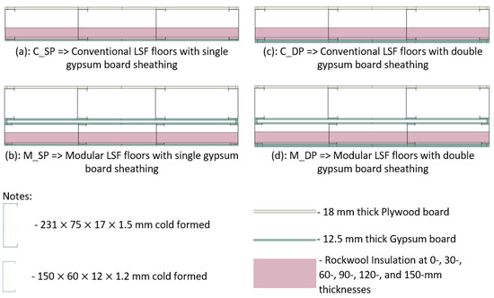
Figure 7.
Parametric floor systema; (a): C_SP; (b): M_SP; (c): C_DP & (d) M_DP.
The parametric floor systems were modelled using FEM methods described in the previous section followed by HTA with standard fire temperature exposure on the bottom side of each floor system. The resultant temperature contours for durations of 4 h were produced from which the through-floor thickness temperatures could be extracted for further analyses to determine structural and insulation fire ratings. From the 48 parametric floors, temperature contours and time variant temperatures associated with the M_DP_120RW floor system are illustrated in Figure 8 and Figure 9, respectively.
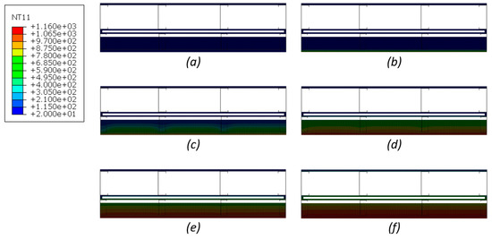
Figure 8.
Temperature contours on M_DP_120RW floor specimen cross-section at (a) 0 min; (b) 30 min; (c) 60 min; (d) 120 min; (e) 180 min; (f) 240 min exposure to standard fire.
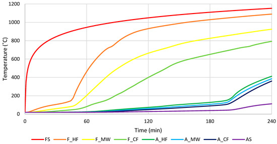
Figure 9.
Time variant temperature through floor thickness of M_DP_120RW floor system.
The locations through floor thickness can be referred to as presented in Figure 10.
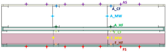
Figure 10.
Through thickness temperature monitoring locations.
The HTA results of floor systems were analysed against the LR versus critical steel temperature explained in Section 2 for the determination of the structural FRL. The mid-web (MW) temperature variations in floor joists are the critical steel temperatures corresponding to the structural failure of steel joists which are designed to act in bending. Hence, the MW temperature variations were analysed against the critical steel temperatures related to different LR values. As the MW of the floor joists reaches the critical steel temperature related to the applied LR, the structural failure of the joist will be initiated. Hence, the time elapsed for the MW of the floor joist to reach the critical steel temperature is the structural FRL of the corresponding floor system. The structural FRLs determined for parametric floor systems are graphically presented in Figure 11.
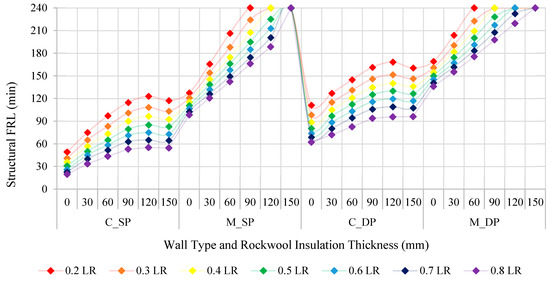
Figure 11.
Structural FRLs of parametric floors.
The overall results indicate that the structural FRL is inversely related to the applied LR of the steel joists. For both conventional and modular LSF floor designs, double-layer sheathing resulted in a 30 min increase in the structural fire rating. Obviously, the modular floor systems demonstrate enhanced structural fire resistance due to the additional heat transfer barriers on the fire side when compared against the conventional floor panel arrangement. However, the thicker designs would not be the ideal option for the building designers to obtain the required fire ratings.
In addition, the incorporation of cavity insulation proved to have a positive influence on the structural FRL. The higher the insulation volume the better the structural fire behaviour; however, slightly different influences can be noticed between conventional and modular types of floor systems. With respect to the conventional floor designs, the increase in rockwool insulation from 0 to 90 mm caused a roughly linear improvement in the structural fire rating; however, further increase in cavity insulation did not result in further improvements. Modular LSF floor systems, however, have been able to increase the structural FRL, as the insulation volume is increased in the whole range. These characteristic behaviours could be explained with the location of the cavity insulation in relation to the floor joists. In the conventional floor designs, the cavity insulation was included in the cavities between floor joists. When rockwool insulation volume inside the cavity is less than half of the cavity volume, a greater portion of the steel joist is not embedded inside the rockwool insulation, and hence the heat trapped inside the cavities and especially on the mid-web of the joist section is limited. However, when the insulation volume is further increased, heat trapped inside the cavities and on the steel joist is increased, leading the joist to reach critical steel temperatures earlier.
On the other hand, in the modular floor panel designs rockwool was included inside ceiling leaf cavities, since the closer the insulation is to the fire side the more effective it will be on fire performance. In that event, with respect to the floor joists, the insulation is located outside the cavity. Therefore, the increase in external insulation volume will always be related to increased structural FRL. The only reason for the structural FRLs being capped at 240 min is that the HTA were conducted up to that time limit, following the convention.
The same HTA results and temperature variations were used to evaluate the insulation FRLs. Here, the unexposed or the ambient side (AS) temperature of the floor specimens were analysed against 160 °C (average) and 200 °C (maximum) thresholds. Time taken for each specimen to reach these limits was taken as the insulation fire ratings, as presented in Figure 12.
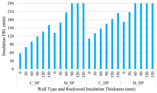
Figure 12.
Insulation FRLs of parametric floor systems.
The characteristics of insulation FRLs of the conventional modular floor systems could be conveniently related to each considered variable. Double plasterboard sheathing against single sheathing options resulted in more than 30 min insulation FRL improvements in both types. From conventional to modular LSF floor systems, the insulation FRL could be enhanced by more than one hour. The increase in insulation volume simply continued to improve the insulation FRL in both conventional and modular designs. However, in conventional designs, where the insulation is integrated inside floor joist cavities, a 30 mm increase in the cavity insulation thickness resulted in an approximate 20 min rise in the insulation FRL. Meanwhile, a 30 mm increase in the ceiling insulation in modular floor designs resulted in a more than 30 min enhancement in the insulation FRLs.
Both structural and insulation fire resistances could be positively influenced by providing more gypsum board layers on the fire side. Modular designs perform better in terms of both structural and insulation fire resisting criteria due to the double skin nature of the build. The insulation material will be more effective if placed external to the structural loadbearing elements, which are the steel joists in this study. When the insulation material is placed inside the gaps of loadbearing structural members (steel joists), heat trapped in the insulation material could elevate the steel temperature and accelerate the time to reach the critical steel temperature. Therefore, if not for the potential increased panel thickness, external insulation would be a better option than the internal cavity insulation. Table 3 presents the summary of fire ratings determined for the parametric floor systems from the HTA. However, the convention of industry is to specify the FRL in 30 min steps. Hence, following this convention, FRLs for each floor system are presented in Table 4.
Table 3.
Exact FLRs of parametric floor systems evaluated from HTA.
Table 4.
FLRs of parametric floor systems specified in accordance with the industry convention.
5. Summary
Fire ratings of typical conventional and modular Light-gauge Steel Frame (LSF) floor systems were investigated adopting comprehensive Finite Element Modelling (FEM) techniques and Heat Transfer Analyses (HTA) studies. The fire performance investigations were based on standard fire exposure of the bottom side of the floor panels. Elevated temperature thermal properties of building materials and FEM techniques were thoroughly reviewed against the theoretical fundamentals and further validated using available full-scale fire experimental studies implemented on LSF structures. The experimental and numerical time–temperature plots were very well matched; hence, the validity of the thermal properties and FEM methods was well-established prior to the modelling of parametric floors and generating the HTA results.
Meanwhile, in both conventional and modular LSF floor designs, channel section joists in the floor panel are designed to take structural loads off the floor panel. Hence, the critical steel temperature of the floor joists must be considered when evaluating the structural Fire Resistance Level (FRL). Since floor joists support the loads acting in bending, the average or the mid-web temperature was found to be related to the critical steel temperature. A series of numerical and experimental studies on the structural fire failures of channel section steel joists were incorporated in establishing a correlation between the applied Load Ratio (LR) and the critical (mid-web) steel temperature of the joists at the structural fire failure. This correlation was used in the current study as an effective simplified method of evaluating the structural fire failure of the LSF floor systems when the time variant temperature of the mid-web of steel joist was produced from HTA. Furthermore, temperature distributions of the unexposed surface of the floor systems were reviewed against average and maximum thresholds specified in Eurocode 3 for the insulation FRL.
Additional gypsum board sheathing on the fire side of the floor systems was quite beneficial for improving both structural and insulation FRLs by at least 30 min. Fire performances of steel modular floors were better than the mapped conventional LSF floors due to the double skin nature of the modular systems.
Structural and insulation FRLs were found to improve with increase in insulation volume in the floor systems. However, increase in insulation volume beyond the half height of the cavity was not effective for conventional floor systems on their structural fire ratings, as the heat trapped in the insulation accelerates the temperature rise in the steel joists. Anyway, the modular floors incorporated the insulation material in the ceiling cavities, and hence the insulation can be considered as external insulation with respect to the floor panel joists which are the structural load bearers of the design. Therefore, the structural members are more protected in modular floor systems so that the structural FRL continued to increase with the increase in insulation volume. Nevertheless, the insulation FRLs of both conventional and modular floor systems were positively influenced as the insulation thickness was increased. Again, ceiling insulation in modular floors proved to be more effective than the cavity insulation in conventional floors.
The research findings on the structural and insulation FRLs of conventional and modular floor systems intend to broaden the applications in the industry of choosing optimum designs that cater to the design requirements. Furthermore, the energy rating of these fire-rated floor systems was identified as a research scope that could even optimise the LSF and Modular Building System construction practices.
The present study focused on the currently broadly practiced LSF and steel modular floor systems in the industry. As more innovative and novel floor systems could be investigated, the authors suggest the necessity of expanding the investigations on LSF and steel modular floor systems for energy and fire ratings to enhance the standards of modular construction culture.
Author Contributions
Conceptualization, K.P.; Funding acquisition, K.P.; Supervision, K.P., K.O. and B.N.; Writing—original draft, D.P. and I.R.U.; Writing—review & editing, E.K. and H.R. All authors have read and agreed to the published version of the manuscript.
Funding
The authors would like to acknowledge ESS Modular Limited and Northumbria University for the financial support and research facilities.
Data Availability Statement
Not applicable.
Acknowledgments
The authors would like to acknowledge ESS Modular Limited and Northumbria University for the financial support and research facilities.
Conflicts of Interest
The authors declare no conflict of interest.
Abbreviations
| AS | Ambient Side |
| C_DP | Conventional LSF Walls with Double Layers of Plasterboard Sheathing |
| C_SP | Conventional LSF Walls with Single Layer of Plasterboard Sheathing |
| CAE | Computer-Aided Engineering |
| CF | Cold Flange |
| FEM | Finite Element Modelling |
| FRL | Fire Resistance Level |
| FS | Fire Side |
| HF | Hot Flange |
| HTA | Heat Transfer Analyses |
| IR | Insulation Ratio |
| LR | Load Ratio |
| LSF | Light-gauge Steel Frame |
| M_DP | Steel Modular Walls with Double Layers of Plasterboard Sheathing |
| M_SP | Steel Modular Walls with Single Layer of Plasterboard Sheathing |
| MBS | Modular Building Systems |
| MEP | Mechanical, Electrical and Plumbing |
| MW | Mid-Web |
| RW | Rockwool Insulation |
References
- Baleshan, B.; Mahendran, M. Experimental study of light gauge steel framing floor systems under fire conditions. Adv. Struct. Eng. 2017, 20, 426–445. [Google Scholar] [CrossRef]
- Gatheeshgar, P.; Poologanathan, K.; Thamboo, J.; Roy, K.; Rossi, B.; Molkens, T.; Perera, D.; Navaratnam, S. On the fire behaviour of modular floors designed with optimised cold-formed steel joists. Structures 2021, 30, 1071–1085. [Google Scholar] [CrossRef]
- Jatheeshan, V. Numerical and Experimental Studies of Cold-Formed Steel floor Systems Made of Hollow Flange Section Joists in Fire. Ph.D. Thesis, Queensland University of Technology, Brisbane, Australia, 2015. Available online: https://eprints.qut.edu.au/120145/ (accessed on 1 October 2022).
- Steau, E.; Keerthan, P.; Mahendran, M. Thermal Modelling of LSF Floor Systems Made of Lipped Channel and Hollow Flange Channel Section Joists; Ernst & Sohn GmbH: Copenhagen, Denmark, 2017; Available online: https://onlinelibrary.wiley.com/doi/epdf/10.1002/cepa.313 (accessed on 1 October 2022).
- Steau, E.; Mahendran, M. Elevated temperature thermal properties of fire protective boards and insulation materials for light steel frame systems. J. Build. Eng. 2021, 43, 102571. [Google Scholar] [CrossRef]
- Steau, E.; Mahendran, M. Thermal modelling of LSF floor-ceiling systems with varying configurations. Fire Saf. J. 2020, 118, 103227. [Google Scholar] [CrossRef]
- Chen, W.; Jiang, J.; Ye, J.; Zhao, Q.; Liu, K.; Xu, C. Thermal behavior of external-insulated cold-formed steel non-load-bearing walls exposed to different fire conditions. Structures 2020, 25, 631–645. [Google Scholar] [CrossRef]
- Chen, W.; Ye, J.; Bai, Y.; Zhao, X.-L. Improved fire resistant performance of load bearing cold-formed steel interior and exterior wall systems. Thin-Walled Struct. 2013, 73, 145–157. [Google Scholar] [CrossRef]
- Chen, W.; Ye, J.; Li, X. Fire experiments of cold-formed steel non-load-bearing composite assemblies lined with different boards. J. Constr. Steel Res. 2019, 158, 290–305. [Google Scholar] [CrossRef]
- Santos, P.; Gonçalves, M.; Martins, C.; Soares, N.; Costa, J.J. Thermal transmittance of lightweight steel framed walls: Experimental versus numerical and analytical approaches. J. Build. Eng. 2019, 25, 100776. [Google Scholar] [CrossRef]
- Perera, D.; Poologanathan, K.; Gatheeshgar, P.; Upasiri, I.R.; Sherlock, P.; Rajanayagam, H.; Nagaratnam, B. Fire performance of modular wall panels: Numerical analysis. Structures 2021, 34, 1048–1067. [Google Scholar] [CrossRef]
- Perera, D.; Poologanathan, K.; Gillie, M.; Gatheeshgar, P.; Sherlock, P.; Nanayakkara, S.M.A.; Konthesingha, K.M.C. Fire performance of cold, warm and hybrid LSF wall panels using numerical studies. Thin-Walled Struct. 2020, 157, 107109. [Google Scholar] [CrossRef]
- Perera, D.; Poologanathan, K.; Gillie, M.; Gatheeshgar, P.; Sherlock, P.; Upasiri, I.R.; Rajanayagam, H. Novel conventional and modular LSF wall panels with improved fire performance. J. Build. Eng. 2022, 46, 103612. [Google Scholar] [CrossRef]
- Perera, D.; Upasiri, I.R.; Poologanathan, K.; Gatheeshgar, P.; Sherlock, P.; Hewavitharana, T.; Suntharalingam, T. Energy performance of fire rated LSF walls under UK climate conditions. J. Build. Eng. 2021, 44, 103293. [Google Scholar] [CrossRef]
- Perera, D.; Upasiri, I.R.; Poologanathan, K.; Perampalam, G.; O’Grady, K.; Rezazadeh, M.; Rajanayagam, H.; Hewavitharana, T. Fire performance analyses of modular wall panel designs with loadbearing SHS columns. Case Stud. Constr. Mater. 2022, 17, e01179. [Google Scholar] [CrossRef]
- Rusthi, M.; Ariyanayagam, A.D.; Mahendran, M. Fire design of LSF wall systems made of web-stiffened lipped channel studs. Thin-Walled Struct. 2018, 127, 588–603. [Google Scholar] [CrossRef]
- Rusthi, M.; Keerthan, P.; Mahendran, M.; Ariyanayagam, A. Investigating the fire performance of LSF wall systems using finite element analyses. J. Struct. Fire Eng. 2017, 8, 354–376. [Google Scholar] [CrossRef]
- Union, T.E. Eurocode 3: Design of Steel Structures—Part 1–2: General Rules—Structural Fire Design; European Commission: Brussels, Belgium, 2005. [Google Scholar]
- Gunalan, S. Structural Behaviour and Design of Cold-Formed Steel Wall Systems under Fire Conditions. Ph.D. Thesis, School of Urban Development, Faculty of Environment and Engineering, Quinsland University of Technology, Brisbane, Australia, 2011. [Google Scholar]
- Kesawan, S.; Mahendran, M. Fire tests of load-bearing LSF walls made of hollow flange channel sections. J. Constr. Steel Res. 2015, 115, 191–205. [Google Scholar] [CrossRef]
- Baleshan, B. Numerical and Experimental Studies of Cold-Formed Steel Floor Systems under Standard Fire Conditions. Ph.D. Thesis, Queensland University of Technology, Brisbane, Australia, 2012. [Google Scholar]
- Jatheeshan, V.; Mahendran, M. Thermal performance of LSF floors made of hollow flange channel section joists under fire conditions. Fire Saf. J. 2016, 84, 25–39. [Google Scholar] [CrossRef][Green Version]
- Abaqus Theory Manual. Dassault Systèmes. Available online: http://130.149.89.49:2080/v6.9/books/stm/default.htm?startat=book01.html (accessed on 10 August 2022).
- Keerthan, P.; Mahendran, M. Numerical studies of gypsum plasterboard panels under standard fire conditions. Fire Saf. J. 2012, 53, 105–119. [Google Scholar] [CrossRef][Green Version]
- Lei, Y.; Xiao, C.; Wang, X.; Yue, J.; Zhu, Q. Tensile properties and fracturing behavior of weld joints in the CLAM at high temperatures. Fusion Eng. Des. 2015, 95, 27–33. [Google Scholar] [CrossRef]
- Huang, Y.; Luo, X.; Zhan, Y.; Chen, Y.; Yu, L.; Feng, W.; Xiong, J.; Yang, J.; Mao, G.; Yang, L.; et al. High-temperature creep rupture behavior of dissimilar welded joints in martensitic heat resistant steels. Eng. Fract. Mech. 2022, 273, 108739. [Google Scholar] [CrossRef]
- He, B.; Cui, L.; Wang, D.; Liu, Y.; Liu, C.; Li, H. The metallurgical bonding and high temperature tensile behaviors of 9Cr-1W steel and 316L steel dissimilar joint by friction stir welding. J. Manuf. Process. 2019, 44, 241–251. [Google Scholar] [CrossRef]
- Gunalan, S.; Mahendran, M. Fire performance of cold-formed steel wall panels and prediction of their fire resistance rating. Fire Saf. J. 2014, 64, 61–80. [Google Scholar] [CrossRef]
- Upasiri, I.; Konthesingha, C.; Nanayakkara, A.; Poologanathan, K.; Perampalam, G.; Perera, D. Finite element analysis of lightweight concrete-filled LSF walls exposed to realistic design fire. J. Struct. Fire Eng. 2022, 13, 506–534. [Google Scholar] [CrossRef]
- Roque, E.; Santos, P. The Effectiveness of Thermal Insulation in Lightweight Steel-Framed Walls with Respect to Its Position. Spec. Issue Insul. Mater. Resid. Build. 2017, 7, 13. [Google Scholar] [CrossRef]


Publisher’s Note: MDPI stays neutral with regard to jurisdictional claims in published maps and institutional affiliations. |
© 2022 by the authors. Licensee MDPI, Basel, Switzerland. This article is an open access article distributed under the terms and conditions of the Creative Commons Attribution (CC BY) license (https://creativecommons.org/licenses/by/4.0/).