Article

Lateral Pressure Test of Vertical Joint Concrete and Formwork Optimization Design for Monolithic Precast Concrete Structure

1
School of Civil Engineering and Communications, North China University of Water Resources and Electric Power, Zhengzhou 450045, China
2
International Joint Research Lab for Eco-building Materials and Engineering of Henan, School of Civil Engineering and Communications, North China University of Water Resources and Electric Power, Zhengzhou 450045, China
3
Collaborative Innovation Center for Efficient Utilization of Water Resources, North China University of Water Resources and Electric Power, Zhengzhou 450045, China
*
Author to whom correspondence should be addressed.
Buildings 2022, 12(3), 261; https://doi.org/10.3390/buildings12030261
Submission received: 29 January 2022 / Revised: 19 February 2022 / Accepted: 21 February 2022 / Published: 23 February 2022
(This article belongs to the Section Building Materials, and Repair & Renovation)

Abstract

:
When the vertical joints of monolithic precast concrete structures are cast by self-compacting concrete, the design of the formwork under rational lateral pressure of self-compacting concrete becomes a key technical issue. In this paper, a prototype simulation test was conducted for the pouring of self-compacting concrete in the vertical joint of precast concrete walls. The self-compacting concrete was continuously poured from the top of vertical joints with a height of 2.8 m without any assistance such as a delivery tube. The formwork pressure of self-compacting concrete was measured at different heights with varying casting time. Results showed that the lateral pressure increased with the increase in slump-flow of fresh self-compacting concrete, reaching a peak value of about 70 kPa at a height of about 600 mm from the bottom of formwork. Compared to the concrete with a slump-flow of 550 mm, the self-compacting concrete with the slump-flow reached 655 mm and 755 mm, presenting an increase in the peak lateral pressure by 31.5% and 44.9%, respectively. A method for calculating the lateral pressure of self-compacting concrete on the joint formwork is proposed using the analysis of enveloped test curves. Under the condition with enough strength and limited deformation of the joint formwork, the optimal design of aluminum alloy formwork is determined using finite element analysis. This provides a sci-tech foundation of the optimal design to lighten the weight of joint formwork to improve the installation efficiency and reduce the manual power cost.

1. Introduction

Self-compacting concrete (SCC) is a high-performance concrete with high flowability, homogeneity, and stability, which flows and fills the formwork through self-weight without the help of any vibration [1]. Compared to a fresh mix of conventional vibrated concrete, SCC has an obviously increased flowability which can even reach the rheological behavior of viscous liquid. Therefore, the lateral pressure of fresh SCC on formwork will be higher than that of conventional vibrated concrete, as it is evidently increased with the flowability of fresh concrete [1,2]. The lateral pressure of SCC varies with the changes in rheological properties induced by different mix proportions. A higher lateral pressure on the formwork by the SCC results from the increase in binder content and the increased replacement of Portland cement with a rational percentage of limestone powder and fly ash, due to the increases in slump-flow and the decrease in dynamic yield stress of fresh SCC [3,4].The lateral pressure can be reduced by admixing a small content of processed clay, metakaolin, and purified wet-processed attapulgite clay composed of magnesium aluminosilicate, due to their effective enhancement of the shear resistance of fresh SCC [5]. In contrast, the lateral pressure can be reduced with the incorporation of fly ash in some conditions [6,7]. Furthermore, the lateral pressure can be reduced by using a rheology control additive due to the increased viscosity of binder paste [8], by increasing the dosage and maximum particle size of coarse aggregate due to the increase in internal friction [4,9,10], and by decreasing the water-to-binder ratio due to the decrease in flowability of fresh SCC [4,6]. If recycled aggregate is used for SCC, the formwork pressure can be reduced due to the higher surface roughness of recycled aggregates, which promotes the internal friction of fresh SCC. The presence of steel bars also reduces the formwork pressure due to the steel bars confining the SCC and bearing part of the pressure [11]. Undoubtedly, the initial peak pressure takes place before the initial setting of binders in SCC. After that, the pressure is reduced with the increase in casting time due to the loss of fluidity of fresh SCC with the continuous hydration of binders.
Meanwhile, the lateral pressure of SCC on formwork is evidently affected by the casting process of SCC and the casting section. With the increase in casting speed, the lateral pressure of SCC is increased due to the fluid impacting force on the formwork [12,13,14,15]. If the filling bottom-up method is used for casting SCC in the column, a pressure higher than hydrostatic pressure is applied to the formwork due to the additional occurring hydraulic losses. This is also related to the casting speed and the viscosity of the SCC [16]. The SCC cast in a 200 mm diameter column exerted slightly less pressure than that cast in a 920 mm column [17]. This is consistent with the finding that the lateral pressure is reduced due to the friction between fresh SCC and formwork [18].
The hydrostatic pressure of SCC can be exerted on formwork according to the specification of China code JGJ/T 283 [1] and American Concrete Institute (ACI) Committee 347 [19]. This has been verified by a wide range of maximum pressure values obtained by different researchers [20]; however, it is simple without considering the effects of any intrinsic or extrinsic factors on the pressure as mentioned above. A previous study proposed a prediction method based on the law derived from ensiled granular media, which considered the casting technique, the rheological characteristics of the SCC, and the state of concrete–wall contacts [21]. Considering the field conditions such as casting speed and procedure, and the friction between fresh SCC and formwork, a two-function model for the formwork pressure exerted by SCC was built using the instantaneous and delayed response functions separately [22].
For monolithic precast shear-wall structures, the casting of vertical joints provides a good location to apply the advantages of SCC. As the reinforcements intersect in a narrow space of the vertical joints, the casting of SCC can minimize the casting difficulty to eliminate the defects of conventional vibrated concrete with uncompacted parts and pores on surfaces [23,24]. However, following a comprehensive analysis of the literature, no study was found on the application of SCC casted in situ into the joints between precast members of monolithic precast concrete structures. This raises the question of whether the current method for predicting the formwork pressure is adaptable to the design of joint formwork. For the optimal design of joint formworks with lightened self-weight for the convenience of in situ installation, the formwork pressure of SCC is a basic parameter that should be determined. Unlike the conventional casting procedure, SCC is cast from the top of the vertical joint without any assistance such as a delivery tube. Therefore, the first task of this study was to detect the lateral pressure of SCC on joint formwork using tests. Then, to lighten the joint formwork for the convenience of manual installation to allow the rapid construction of precast concrete structures, a unitary joint formwork was designed with aluminum alloy in reasonable geometrical sizes and composited with the components to meet the project requirements of joint formwork.

2. Test for Lateral Pressure

2.1. Preparation of SCC

Ordinary Portland cement of grade 42.5 produced by Henan Mengdian Cement Co. Ltd. (Xuchang, China) was used with the physical and mechanical properties presented in Table 1. This met the specifications of China code GB175 [25].
Class II fly ash was used with a density of 2342 kg/m3 and a fineness of 21.8%. Granulated ground blast-furnace slag (GGBS) was used with a density of 2779 kg/m3 and a fineness of 27.9%. Their properties met the specifications of China codes GB/T1596 and GB/T18046, respectively [26,27].
The fine aggregate was a mixture of river sand and artificial sand with a fineness modulus of 2.9, an apparent density of 2690 kg/m3, and a closed packing density of 1725 kg/m3. This met the specifications of China code GB/T14684 [28].
The coarse aggregate consisted of series of 5–10 mm and 10–20 mm with a proportion of 6:4 to form a continuous grading of particles according to the specification of China code GB/T14685 [29]. The apparent density and the closed packing density were 2740 kg/m3 and 1540 kg/m3, the 1 h water absorption was 1.05%, and the crushed index was 9.7%.
The expanding agent produced by Jiangsu Sobote New Materials Co., Ltd. was used. The limit expansion rates were 0.042 (7 days in the water) and 0.075 (21 days in the air). This met the specifications of China code GB/T23439 [30].
The water reducer was a polycarboxylic acid high-performance water reducer with a water reduction of 25%. This met the specifications of China code GB8076 [31].
The strength grade of SCC was prospected as 35 MPa, 40 MPa, and 45 MPa with the target strengths of 43.2 MPa, 48.2 MPa, and 53.2 MPa, respectively. The mix proportions of SCC were designed using the absolute volume method [32,33,34], and the results are presented in Table 2. For SCC with a strength grade of 40 MPa, the slump-flow was changed by adding different dosages of water reducer.
A horizontal-shaft forcing mixer was used for combining the SCC mixture. Crushed limestone and river sand were firstly mixed, and then the cement, fly ash, GGBS, and expanding agent were added, followed by the water and water reducer. The slump-flow of fresh SCC was measured according to China code JGJ/T283 [1], and the results are presented in Table 3. The filling ability of the C35, C40a, and C45 mixes met the grade SF1 with a slump-flow from 550 mm to 655 mm, while that of the C40b mix met the grade SF2 with a slump-flow from 660 mm to 755 mm.
The cubic compressive strength of SCC was tested according to China code GB50081 [35]. For each batch of SCC, six cubic specimens, three as a group, with a dimension of 150 mm were cast for the test of the cubic compressive strength (fcu) at the curing age of 7 days and 28 days. All specimens were cured in the standard curing room. Test results meeting the targets are presented in Table 3.

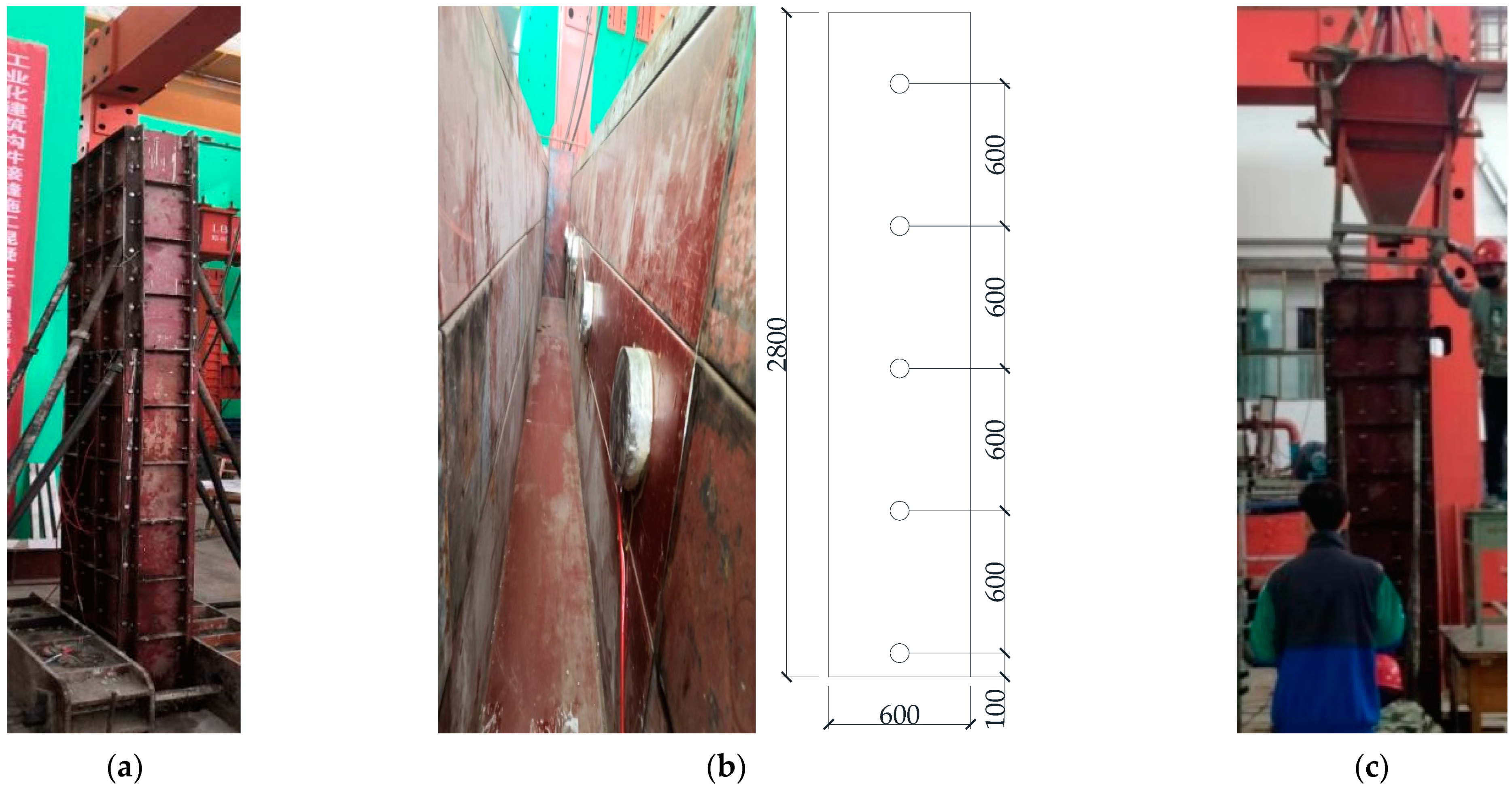
2.2. Test for Lateral Pressure of SCC on Vertical Joint Formworks

The vertical joint was formed by composite steel formworks made of grade Q235 steel plate. One unitary steel formwork was 900 mm long and 200 mm wide with ridges of 50 mm wide. Several unitary steel formworks were composited to form a vertical joint with dimensions of 600 mm width, 200 mm thickness, and 2800 mm height, as shown in Figure 1a. Five JTM-V200 type vibrating wire cells were fixed on the inner surface of formwork along the height, as presented in Figure 1b, which were linked to a JMZX-7000 general-purpose tester to measure the lateral pressure of SCC on formwork at corresponding height. To simulate the casting process of project vertical joints of monolithic precast concrete wall structures, the SCC was filled in the hopper and continuously poured from the top of the vertical joint. The maximum dropping height of casted SCC was 2.8 m without any assistance such as a delivery tube, as presented in Figure 1c, which met the requirement of a dropping height less than 5 m in the wall formwork [1].
The casting procedure time was short due to the high flowability of SCC. Therefore, the data of cells were initially recorded every 20 s for 10 min. Due to the SCC gradually losing plasticity during the setting, the lateral pressure tended to be steady over time. To ensure the integrity of test results, the data were recorded 30 times at an interval of 1 min, 12 times at an interval of 5 min, six times at an interval of 10 min, three times at an interval of 20 min, and four times at an interval of 30 min. The duration of each test was 5 h and 40 min.

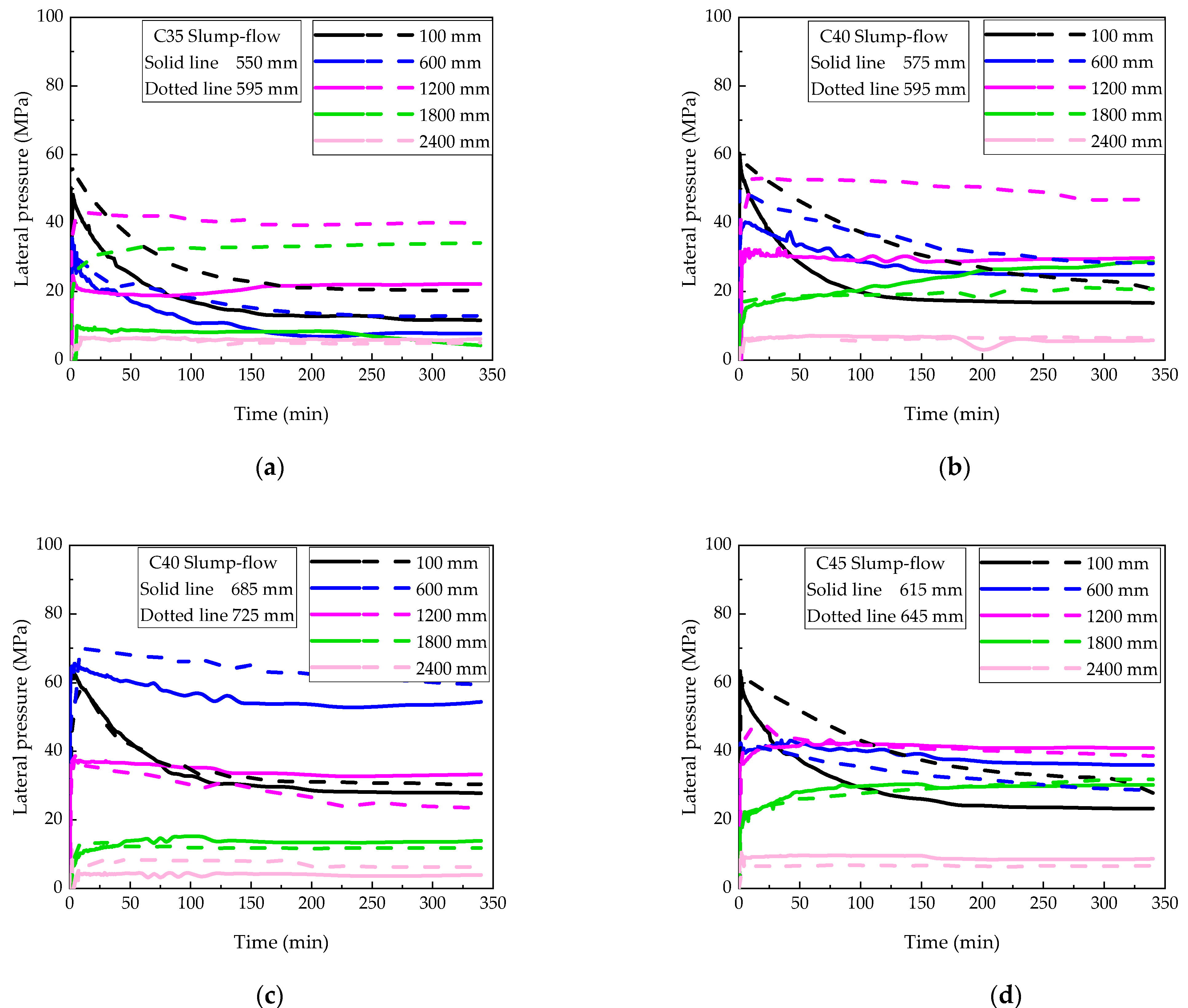
2.3. Test Results of Lateral Pressure

As presented in Figure 2, the lateral pressure of SCC on the formwork reached its peak at a height from 100 mm to 600 mm above the bottom, which was affected by the filling property of SCC. When the filling ability of SCC was grade SF1, the peak lateral pressure appeared at a height of about 100 mm. When the filling ability of SCC was grade SF2, the peak lateral pressure appeared at a height of about 600 mm, increasing by 11.4% on average compared to that at the height of about 100 mm.
With the increase in time after casting, the peak lateral pressure decreased while the lateral pressure at the heights of 1200 mm, 1800 mm, and 2400 mm changed little after the time exceeded 100 min. This was due to the decrease in flowability of fresh SCC with the continuous hydration of binders after casting. Similar variation was observed by other researchers [3,4,5].
As presented in Figure 3, the initial maximum lateral pressure of SCC on formwork increased with the slump-flow of fresh SCC, slightly influenced by the strength grade of SCC. This indicates that the peak pressure took place before the initial setting of SCC after casting, and the dominant factor was flowability rather than hardened strength. Related to the filling ability of fresh SCC at grades SF1 and SF2, the peak lateral pressure was 63.5 kPa and 70.0 kPa, respectively. Compared to that of fresh SCC with a slump-flow of 550 mm, the peak lateral pressure increased by 31.5% and 44.9% for the SCC with filling ability of grades SF1 and SF2. This is easily understood by the variation of lateral pressure being mainly due to the rheology changes with lower viscous and yield stress with the increase in slump-flow of fresh SCC [13,14,15].
As presented in Figure 4, the peak lateral pressure of SCC on formwork did not linearly decrease with the height of SCC due to the friction between fresh SCC and the formwork surface [18,21,22]. The lateral pressure maintained a higher value within a certain height of formwork. Taking the maximum value of lateral pressure at the same height of formwork for all SCC in this test, the envelop curve of lateral pressure with the peak value at a featured height about 600 mm could be obtained as presented in Figure 4. Almost a linear change existed in lateral pressure above the featured height, which tended to decrease below this height. The main reason for the decrease in formwork pressure can be attributed to the friction between fresh SCC and the bottom surface, which confined the fluidity of SCC.

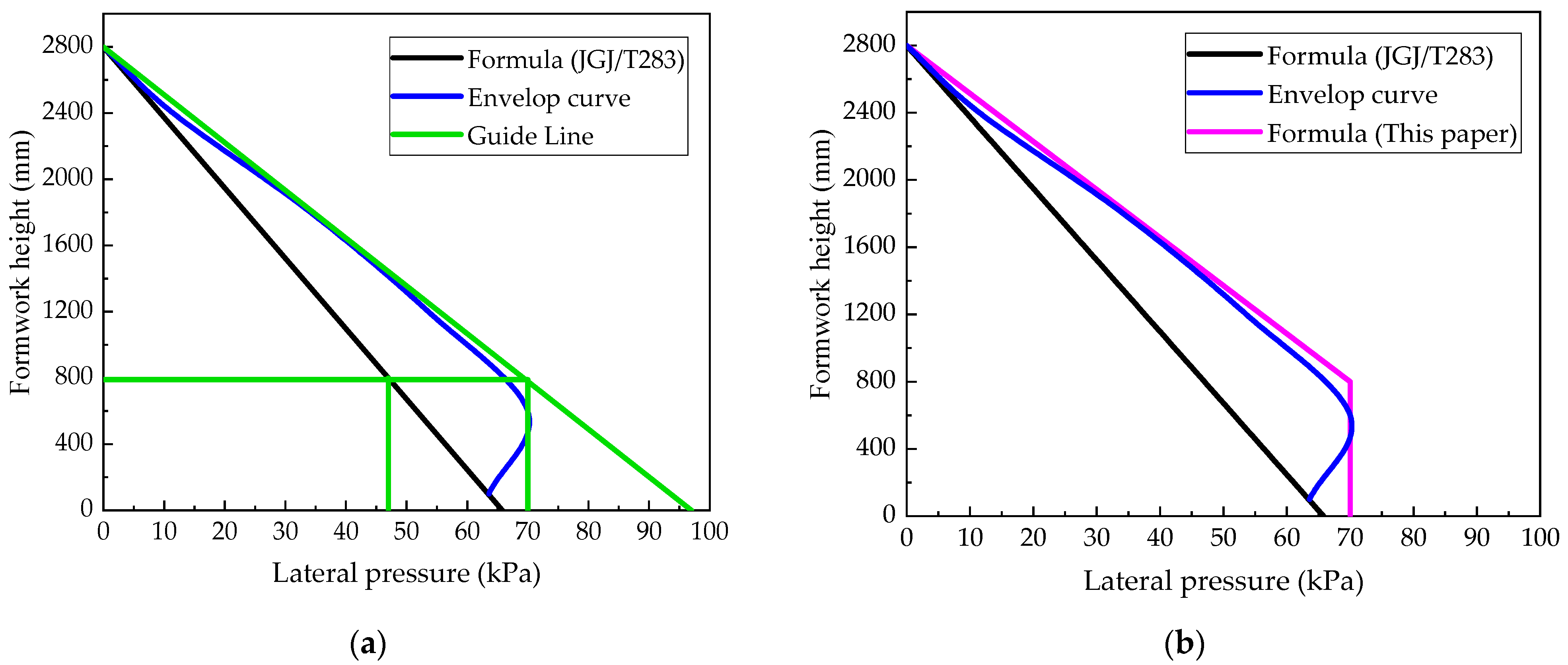
2.4. Prediction of Maximum Lateral Pressure

For the reliable design of formwork, the maximum lateral pressure of SCC is always presumed to be exerted on formwork. According to China code JGJ/T283 [1], the maximum lateral pressure can be calculated as follows:
F = γ c h ,
where F is the maximum lateral pressure (kN/m2), γ c is the unit weight of concrete (kN/m3), and h is the height from the calculated section to the top surface of concrete (m).
Equation (1) is deduced from the hydrostatic pressure with an assumption that it is the same for SCC and water. The calculated value is smaller than the value obtained from the test envelop curve presented in Figure 4. This is due to Equation (1) not considering the dynamic action of SCC falling freely from a high place during the casting. Another reason could be the neglection of the casting speed of SCC; as revealed in the literature, an increase in casting speed can lead to increases in maximum pressure by 15% [13] and 22.5% [15]. Therefore, Equation (1) is inapplicable to the design of joint formwork between precast concrete walls.
As presented in Figure 5a, Equation (1) can be corrected by drawing a line fitted to the almost linear portion of the envelop curve, which gives an enlarging factor of 1.5. Then, the peak pressure of the envelop curve is taken as a limit to get a featured height of 800 mm. This leads to the final double-broken line drawn in Figure 5b. The corrected formula is
F = {                     1.5 γ c h                                   H h > 800     1.5 γ c ( H 800 )               H h 800 ,
where F is the maximum lateral pressure (kN/m2), γ c is the unit weight of concrete (kN/m3), h is the height from the calculated section to the top surface of concrete (m), and H is the total height of concrete (m).
Compared to Equation (1), Equation (2) presents a larger pressure of SCC on formwork. This is more conservative and can be used for the design of joint formwork subjected to SCC pressure.

3. Optimal Design of Vertical Joint Formwork

According to the project of monolithic precast concrete structures, the widths of joints between precast walls are 500 mm, 600 mm, and 700 mm, respectively. To improve the installation efficiency and reduce the manual power cost, the optimal design of unitary formwork and joint formwork was conducted on the basis of a series of analytical comparisons of materials, shapes, and composition methods. The finite element method used for formwork design has been validated by previous studies. Finally, the aluminum alloy plate was selected to form the unitary formwork with widths of 300 mm, 350 mm, and 400 mm. The joint formwork was composed of two unitary formworks with the assistance of back purlin braces and pair bolts. In this section, only the final design and analytical results of formwork for the joint with of 500 mm are presented as an example.

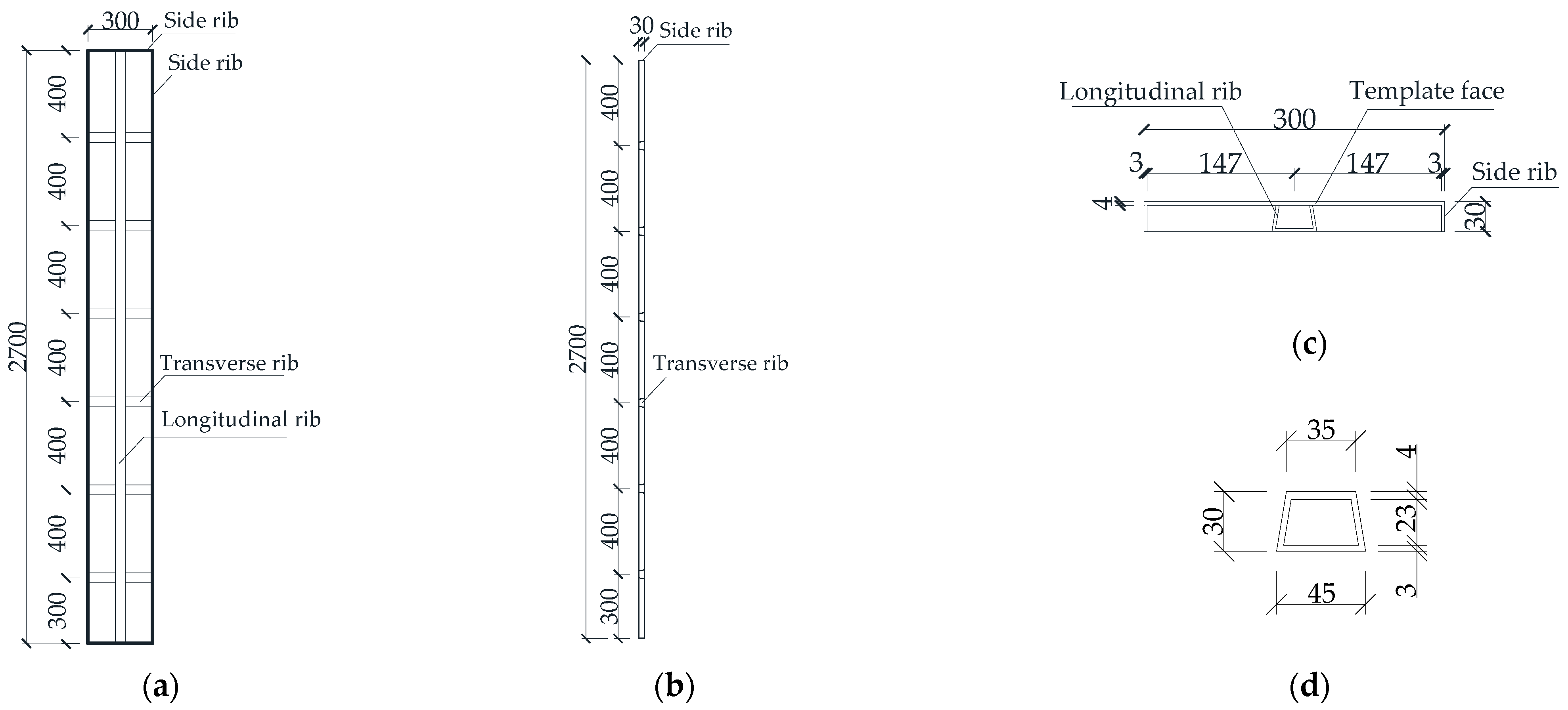
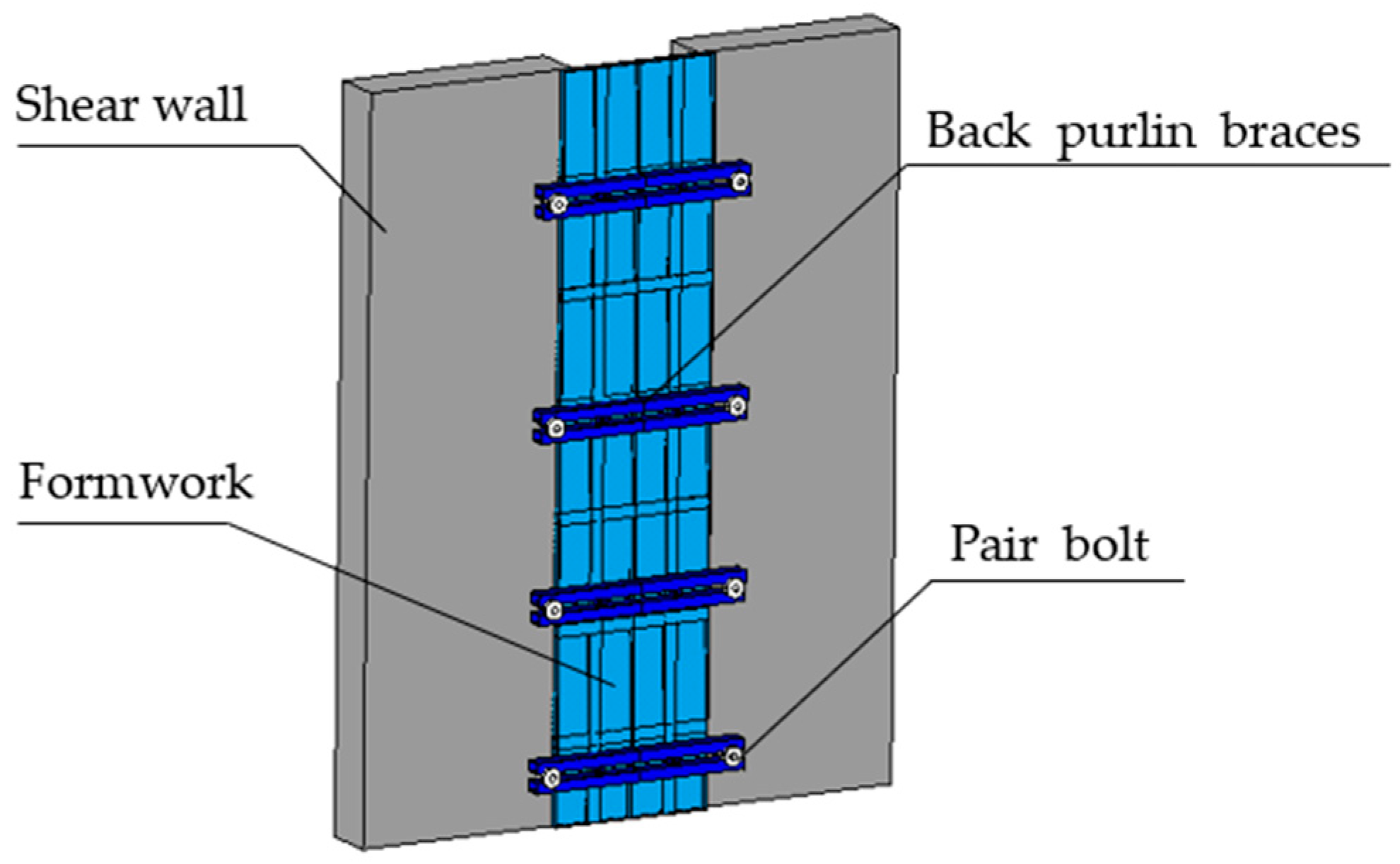
3.1. Basic Information of Joint Formwork
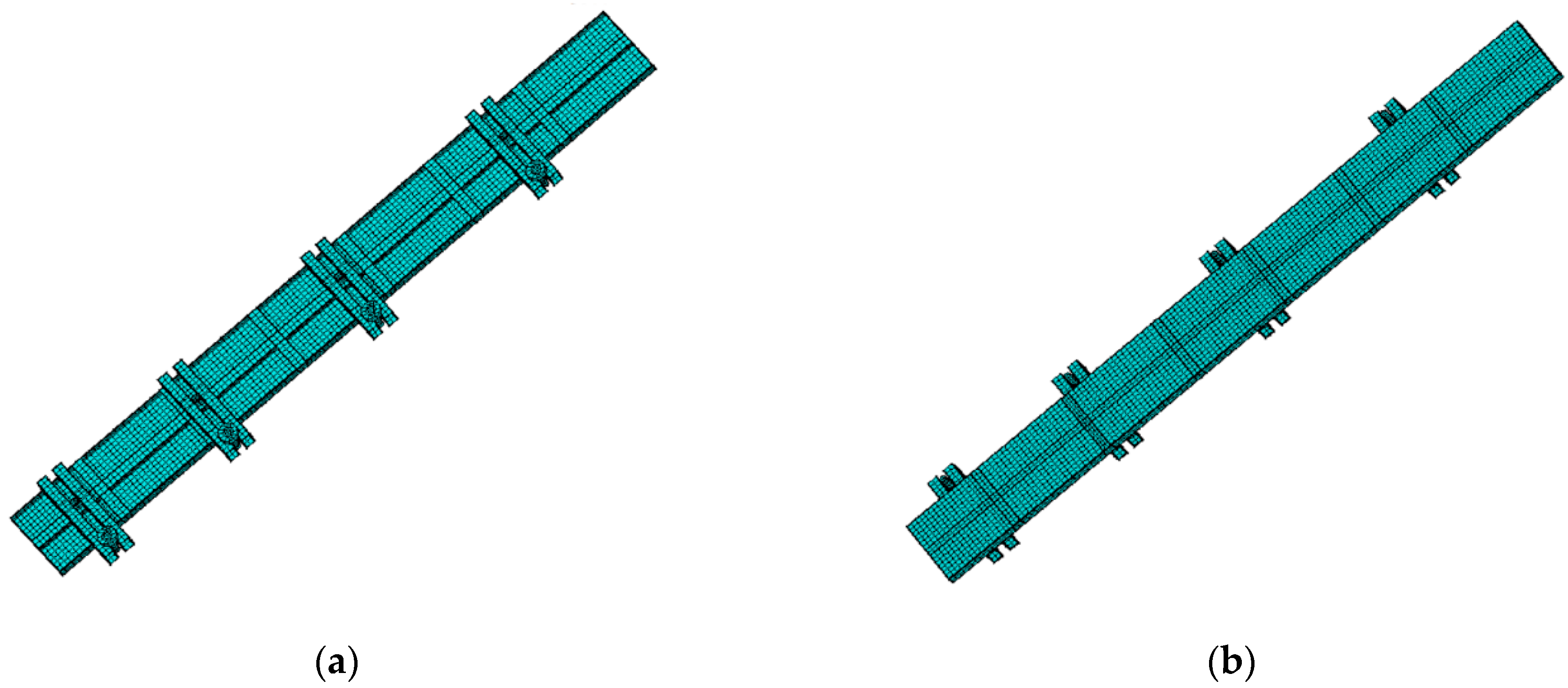
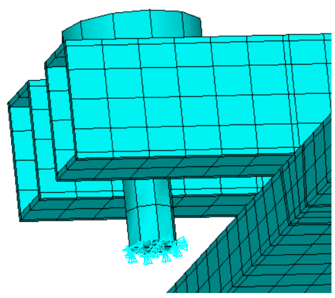
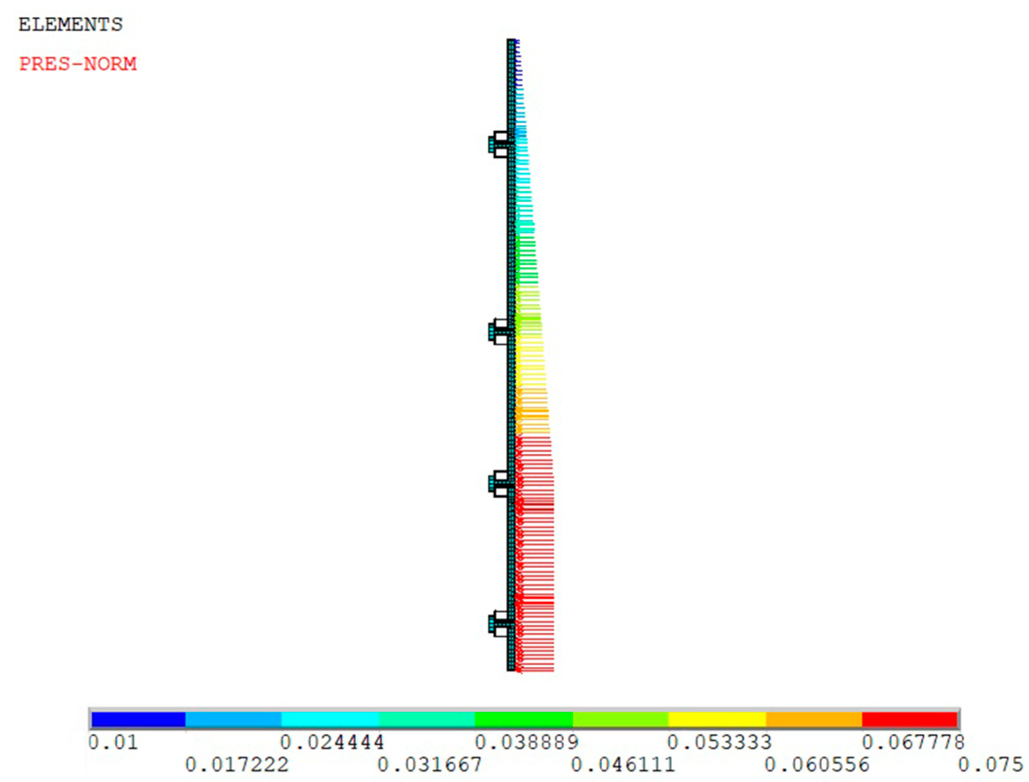
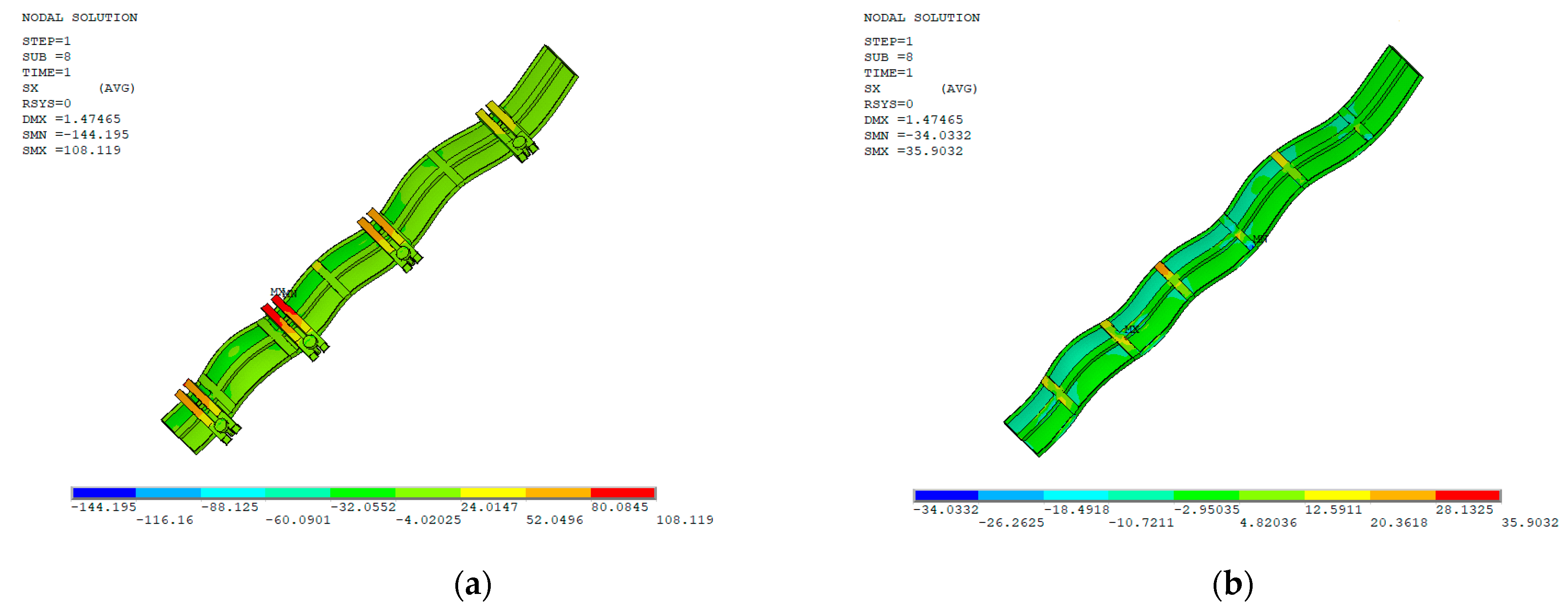
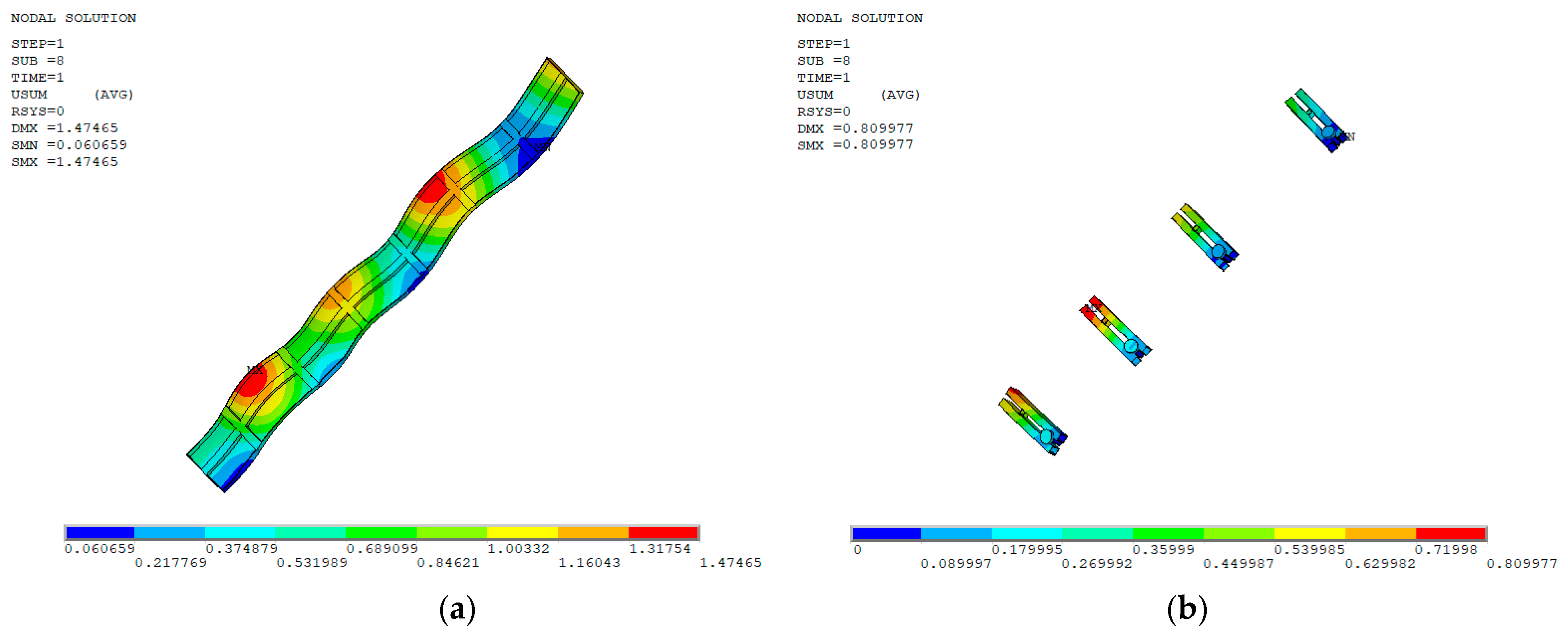
The unitary vertical joint formwork was 300 mm wide and 2700 mm high with a plate thickness of 4 mm. Six horizontal ribs and one vertical rib with a 3 mm thick hollow trapezoid section were designed to ensure the entire stiffness and stability of formwork. The material of formwork was selected as aluminum alloy. Detailed dimensions of the unitary formwork are presented in Figure 6.
For the vertical joint designed with a width of 500 mm, as presented in Figure 7, the joint formwork was spliced by two unitary formworks with a lap length of 50 mm on each side of the wall. To ensure that the entirety of formwork was integrally subjected to the lateral pressure of SCC, back purlin braces and pair bolts were used to bind the unitary formworks together and fix them to the precast walls. The back purlin braces and bolts were steel. The braces were hollow with a section of 40 mm × 60 mm and a shell thickness of 3 mm. The braces were placed on the back of the formwork at a height from the bottom of 200 mm, 800 mm, 1450 mm, and 2250 mm. The diameter of the bolts was 12 mm.
The mechanical properties and density of materials for formwork and components are presented in Table 4.

3.2. FEM Model

The formwork was simulated using finite element Solide185 in ANSYS software. Solide185 is a hexahedral element which has good convergence and accuracy. The mesh of the elements is presented in Figure 8. The original point of coordinates was set to the left corner, where the X-axis is the horizontal width, the Y-axis is the vertical height, and the Z-axis is the horizontal thickness.
As a semi-structure was built, the symmetry constraint was applied to the plane X = 0. To simulate the fixing of bolts on the formwork, a plane restraint was added along X-, Y-, and Z-axes on the ends of bolts located at Y = 200 mm, 800 mm, 1450 mm, and 2250 mm, as presented in Figure 9.
As presented in Figure 10, the lateral pressure exerted on the inner surface of the formwork was calculated using Equation (2) with a peak value of 75 kPa at a height of 800 mm.

3.3. Optimal Results

With elastic flexural deformation under lateral pressure, stresses appeared on the formwork along the X- and Y-axes, as shown in Figure 11 and Figure 12. The stress along the X-axis was mainly exerted on the braces, with the maximum tensile stress of 108.2 MPa and the maximum compressive stress of 144.2 MPa appearing on the second brace at a formwork height of 1450 mm. A relatively uniform stress distribution appeared on the formwork. This indicates that the braces played a main role in restricting formwork deformation.
Compared to the stress along the X-axis, the stress along the Y-axis was relatively uniform with little change. The maximum tensile stress of 58.0 MPa appeared in the middle of the edge rib between the first and second braces, while the maximum compressive stress of 94.3 MPa appeared on the edge rib of the formwork connected to the second brace. This indicates that the constraint effect of vertical ribs was prominent with a higher stress under lateral pressure of SCC.
Compared to the stresses along X- and Y-axes, the Z-axis was parallel to the direction of lateral pressure. As presented in Figure 13, the maximum stresses all appeared in the contact surfaces between the bolt and brace, as well as between the brace and formwork. The maximum tensile stress of 110.3 MPa appeared on the contact surface between the second brace and bolt, while the maximum compressive stress of 60.7 MPa appeared on the contact surface between the third brace and formwork. The maximum tensile stress of 61.0 MPa and the maximum compressive stress of 60.2 MPa of the formwork appeared near the edge rib of the formwork contact with the second brace.
As exhibited in Figure 14, the deformation of formwork decreased from mid-section to the ends along the width, with the maximum deformation of 0.81 mm at the mid-section of the second brace. Along the height of the formwork, a larger deformation appeared at the mid-section between adjacent braces. The maximum value was 1.48 mm at the cantilever ends of the formwork. This meets the requirements of China code JGJ386 whereby the deformation of the unitary formwork should be less than a span of 1/400 and 1.5 mm, while that of the brace should be less than a span of 1/500 and 2.0 mm [36]. Generally, the braces provided important constraints to the deformation of the formwork, while the horizontal and vertical ribs had a limited enhancing effect on the stiffness of formwork to control the deformation.
Therefore, the maximum stresses appearing on the formwork and components were all within the limits of the material strength, as presented in Table 4. The deformation of formwork met the requirement of ensuring the casting size of SCC in the joints.

4. Conclusions

The lateral pressure of fresh self-compacting concrete on the vertical joint formwork was detected using the simulation prototype test, before being used for the optimal design of formwork. On the basis of this study, the following conclusions can be drawn:
(1) The lateral pressure of self-compacting concrete on formwork increases with the slump-flow of self-compacting concrete, while it is slightly influenced by the strength grade of self-compacting concrete.
(2) The lateral pressure reaches a peak value at a featured height at the bottom of formwork, and it tends to linearly decrease above this height. The peak value decreases over time after casting of self-compacting concrete, while the lateral pressure above this height is almost constant after a casting time over 100 min.
(3) On the basis of the test results of this study, a method for the prediction of lateral pressure of self-compacting concrete on joint formwork was proposed to envelop the maximum values of all self-compacting concrete (SCC) tested. The pressure predicted using this method is higher than that predicted by the hydrostatic pressure specified in current China code JGJ/T283. The higher pressure can be used for the safe design of vertical joint formwork for monolithic precast concrete structures. The formwork pressure takes place under the condition of pouring self-compacting concrete (SCC) from the top of the joint without any assistance such as a delivery tube. Therefore, the adaptability of this method needs to be verified for the design of formwork of self-compacting concrete (SCC) structures cast in situ.
(4) The vertical joint formwork was optimally designed by finite element analysis. The section presented in this paper met the limits of deformation and stress. This led to a 25% decrease in the weight of vertical joint formwork with thinner plates compared to the conventional aluminum alloy formwork. As a result, labor costs can be reduced due to the convenient installation of the joint formworks.

Author Contributions

Methodology, Y.Y. and X.D.; validation, S.Z.; investigation and data curation X.D., Y.L., L.D. and F.L.; writing—original draft preparation, Y.L. and X.D.; writing—review and editing, Y.Y. and S.Z.; funding acquisition, S.Z. All authors read and agreed to the published version of the manuscript.

Funding

This research was funded by the State Key Research and Development Plan, China (grant number 2017YFC0703904), the Special Joint Research Project of Zhengzhou City and NCWU (grant number 2021014), and the Innovative Sci-Tech Team of Eco-building Material and Structural Engineering of Henan Province, China (grant number YKRZ-6-066).

Institutional Review Board Statement

Not applicable.

Informed Consent Statement

Not applicable.

Data Availability Statement

The data presented in this study are available on request from the corresponding author.

Conflicts of Interest

The authors declare no conflict of interest.

References

  1. JGJ/T 283-2012; Ministry of Housing and Urban-Rural Construction of the People’s Republic of China. Technical Specification for Application of Self-Compacting Concrete. China Construction Industry Press: Beijing, China, 2002.
  2. Proske, T.; Graubner, C. Formwork pressure of highly workable concrete—Experiments focused on setting, vibration and design approach. In Design, Production and Placement of Self-Consolidating Concrete; Khayat, K.H., Feys, D., Eds.; RILEM Books Series 1; Springer Science & Business Media: Berlin/Heidelberg, Germany, 2010. [Google Scholar]
  3. Assaad, J.; Khayat, K.H. Kinetics of formwork pressure drop of self-consolidating concrete containing various types and contents of binder. Cem. Concr. Res. 2005, 35, 1522–1530. [Google Scholar] [CrossRef]
  4. Kim, J.H.; Noemi, N.; Shah, S.P. Effect of powder material on the rheology and formwork pressure of self-consolidating concrete. Cem. Concr. Compos. 2012, 34, 746–753. [Google Scholar] [CrossRef]
  5. Kim, J.H.; Beacraft, M.; Shah, S.P. Effect of mineral admixtures on formwork pressure of self-consolidating concrete. Cem. Concr. Compos. 2010, 32, 665–671. [Google Scholar] [CrossRef]
  6. Gregori, A.; Ferron, R.P.; Sun, Z.; Shah, S.P. Experimental simulation of self-consolidating concrete formwork pressure. ACI Mater. J. 2008, 105, 97–104. [Google Scholar]
  7. Wang, Z.L. Research on Rheological Performances and Formwork Pressure of Self-Compacting Concrete. Master’s Dissertation, Harbin Institute of Technology, Harbin, China, 2011. [Google Scholar]
  8. Zhao, C. Effect of Rheology Control Additive on the Lateral Pressure of Self-Compacting Concrete. Master’s Dissertation, Zhejiang University of Technology, Hangzhou, China, 2015. [Google Scholar]
  9. Assaad, J.; Khayat, K.H. Effect of coarse aggregate characteristics on lateral pressure exerted by self-consolidating concrete. ACI Mater. J. 2005, 102, 145–153. [Google Scholar]
  10. Assaad, J. Variations of lateral and pore water pressure of self-consolidating concrete at early age. ACI Mater. J. 2004, 101, 310–317. [Google Scholar]
  11. Assaad, J.; Matar, P. Regression models to predict SCC pressure exerted on formwork containing vertical and transverse reinforcing bars. Mater. Struct. 2018, 51, 62. [Google Scholar] [CrossRef]
  12. Tejeda-Dominguez, F. Laboratory and Field Study of Self-Consolidating Concrete Formwork Pressure; University of Illinois at Urbana-Champaign: Champaign, IL, USA, 2005. [Google Scholar]
  13. Assaad, J.; Khayat, K.H. Effect of casting rate and concrete temperature on formwork pressure of self-consolidating concrete. Mater. Struct. 2006, 39, 333–341. [Google Scholar] [CrossRef]
  14. Shi, X.W.; Gong, J.; She, X.K. Study on formwork lateral pressure test for self-compacting concrete. Build. Constr. 2015, 37, 1232–1234. [Google Scholar]
  15. Chen, H.; Ye, Y.H.; Xue, Z.H.; Wang, Z.H. Experimental study on formwork pressure produced by SCC in precast shear wall structure. Jiangsu Constr. 2015, 1, 35–50. (In Chinese) [Google Scholar]
  16. Tichko, S.; Schutter, G.D.; Troch, P.; Vierendeels, J.; Verhoeven, R.; Lesage, K.; Cauberg, N. Influence of the viscosity of self-compacting concrete and the presence of rebars on the formwork pressure while filling bottom-up. Eng. Struct. 2015, 101, 698–714. [Google Scholar] [CrossRef]
  17. Khayat, K.H.; Assaad, J.; Mesbah, H.; Lessard, M. Effect of section width and casting rate on variations of formwork pressure of self-consolidating concrete. Mater. Struct. 2005, 38, 73–78. [Google Scholar] [CrossRef]
  18. Kwon, S.H.; Phung, Q.T.; Park, H.Y.; Kim, J.H.; Shah, S.P. Effect of wall friction on variation of formwork pressure over time in self-consolidating concrete. Cem. Concr. Res. 2010, 41, 90–101. [Google Scholar] [CrossRef]
  19. ACI Committee 347. Guide to Formwork for Concrete; American Concrete Institute: Farmington Hills, MI, USA, 2004. [Google Scholar]
  20. Teixeira, S.; Santilli, A.; Puente, I. Analysis of casting rate for the validation of models developed to predict the maximum lateral pressure exerted by self-compacting concrete on vertical formwork. J. Build. Eng. 2016, 6, 215–224. [Google Scholar] [CrossRef]
  21. Vanhove, Y.; Djelal, C.; Magnin, A. Prediction of the lateral pressure exerted by self-compacting concrete on formwork. Magaz. Concr. Res. 2004, 56, 55–62. [Google Scholar] [CrossRef]
  22. Kwon, S.H.; Kim, J.H.; Shah, S.P. Developments and applications of the intrinsic model for formwork pressure of self-consolidating concrete. Intern. J. Concr. Struct. Mater. 2012, 6, 31–40. [Google Scholar] [CrossRef] [Green Version]
  23. JGJ 1-2014; Ministry of Housing and Urban-Rural Development of the People’s Republic of China. Technical Specification for Precast Concrete Structures. China Construction Industry Press: Beijing, China, 2014.
  24. Li, C.Y.; Yang, Y.B.; Su, J.Z.; Meng, H.D.; Pan, L.Y.; Zhao, S.B. Experimental research on interfacial bonding strength between vertical cast-in-situ joint and precast concrete walls. Crystals 2021, 11, 494. [Google Scholar] [CrossRef]
  25. GB 175-2007; General Administration of Quality Supervision, Inspection and Quarantine of the People’s Republic of China. Common Portland Cement. Standards Press of China: Beijing, China, 2007.
  26. GB/T 1596-2017; General Administration of Quality Supervision, Inspection and Quarantine of the People’s Republic of China. Fly Ash Used for Cement and Concrete. Standards Press of China: Beijing, China, 2017.
  27. GB/T 18046-2017; General Administration of Quality Supervision, Inspection and Quarantine of the People’s Republic of China. Ground Granulated Blast Furnace Slag Used for Cement, Mortar and Concrete. Standards Press of China: Beijing, China, 2017.
  28. GB/T 14684-2011; General Administration of Quality Supervision, Inspection and Quarantine of the People’s Republic of China. Sand for Construction. Standards Press of China: Beijing, China, 2011.
  29. GB/T 14685-2011; General Administration of Quality Supervision, Inspection and Quarantine of the People’s Republic of China. Pebble and Crushed for Construction. Standards Press of China: Beijing, China, 2011.
  30. GB/T 23439-2017; General Administration of Quality Supervision, Inspection and Quarantine of the People’s Republic of China. Expansive Agents for Concrete. Standards Press of China: Beijing, China, 2017.
  31. GB 8076-2008; General Administration of Quality Supervision, Inspection and Quarantine of the People’s Republic of China. Concrete Admixtures. Standards Press of China: Beijing, China, 2008.
  32. Zhao, M.L.; Ding, X.X.; Li, J.; Law, D. Numerical analysis of mix proportion of self-compacting concrete compared to ordinary concrete. Key Eng. Mater. 2018, 789, 69–75. [Google Scholar]
  33. Li, C.Y.; Shang, P.R.; Li, F.L.; Feng, M.; Zhao, S.B. Shrinkage and mechanical properties of self-compacting SFRC with calcium sulfoaluminate expansive agent. Materials 2020, 13, 588. [Google Scholar] [CrossRef] [PubMed] [Green Version]
  34. Ding, X.X.; Zhao, M.S.; Qiu, X.; Wang, Y.P.; Ru, Y.J. The optimization of mix proportion design for SCC: Experimental study and grey relational analysis. Materials 2022, 15, 1305. [Google Scholar] [CrossRef]
  35. GB/T 50081-2019; Ministry of Housing and Urban-Rural Development of the People’s Republic of China. Standard for Test Methods of Concrete Physical and Mechanical Properties. China Construction Industry Press: Beijing, China, 2019.
  36. JGJ386-2016; Ministry of Housing and Urban-Rural Development of the People’s Republic of China. Technical Specification for Combined Aluminum Alloy Formwork Engineering. China Construction Industry Press: Beijing, China, 2016.
Figure 1. Lateral pressure test arrangement of vertical joint: (a) vertical joint formwork; (b) arrangement of measuring cells (unit: mm); (c) casting of SCC.
Buildings 12 00261 g001
Figure 2. Lateral pressure on formwork at different heights over time: (a) C35 with slump-flow of 550 mm and 595 mm; (b) C40 with slump-flow of 575 mm and 595 mm; (c) C40 with slump-flow of 685 mm and 725 mm; (d) C45 with slump-flow of 615 mm and 645 mm.
Buildings 12 00261 g002
Figure 3. The change in peak lateral pressure with the slump-flow of fresh SCC.
Buildings 12 00261 g003
Figure 4. The change in maximum lateral pressure with the casting height of SCC.
Buildings 12 00261 g004
Figure 5. Formula derivation: (a) comparison of calculated results; (b) Equation (2).
Buildings 12 00261 g005
Figure 6. Formwork: (a) front view; (b) side view; (c) normal cross-section; (d) rib section.
Buildings 12 00261 g006
Figure 7. Schematic diagram of joint formwork installation.
Buildings 12 00261 g007
Figure 8. FEM model of formwork: (a) outside view; (b) inside view.
Buildings 12 00261 g008
Figure 9. Restraints of formwork on bolts.
Buildings 12 00261 g009
Figure 10. Lateral pressure on formwork.
Buildings 12 00261 g010
Figure 11. Stress nephogram along X-direction: (a) outside view; (b) inside view.
Buildings 12 00261 g011
Figure 12. Stress nephogram along Y-direction: (a) outside view; (b) inside view.
Buildings 12 00261 g012
Figure 13. Stress nephogram along Z-direction: (a) outside view; (b) inside view.
Buildings 12 00261 g013
Figure 14. Strain nephogram along Z-direction: (a) Formwork; (b) Back purlin braces and Pair bolt.
Buildings 12 00261 g014
Table 1. Physical and mechanical properties of cement.
Setting Time (min)Compressive Strength (MPa)Flexural Strength (MPa)Specific Surface Area (m2/kg)Water Requirement of Normal Consistency (%)Apparent Density
(kg/m3)
InitialFinal3 days28 days3 days28 days
17021523.044.14.46.736027.03093
Table 2. Results of mix proportion of SCC.
Group No.w/c Raw Material Dosage (kg/m3)
CementWaterSandCrushed StoneFly AshGGBSExpanded AgentWater Reducer
C350.34326.5185805.8872.954.4108.854.45.44
C40a0.31358.1185782.2847.459.7119.459.76.56
C40b0.31358.1185782.2847.459.7119.459.75.97
C450.28396.4185753.6816.466.1132.166.17.93
Table 3. Test results of slump-flow and cubic compressive strength of SCC.
Group No.Slump-Flow
(mm)
Cubic Compressive Strength (MPa)
7 days28 days
C30-155032.443.8
C30-259531.943.6
C40a-157538.248.6
C40a-259538.949.4
C40b-168539.148.9
C40b-272538.749.4
C45-161542.954.3
C45-264544.155.2
Table 4. Mechanical properties and density of materials for formwork and components.
MaterialDesigned Yield Strength (MPa)Modulus of Elasticity (GPa)Poisson’s RatioDensity (kg/m3)
Aluminum alloy200700.32800
Back purlin braces2152100.37850
Bolt2052100.37850
Publisher’s Note: MDPI stays neutral with regard to jurisdictional claims in published maps and institutional affiliations.

