Article

Shear Enhancement of RC Beams Using Low-Cost Natural Fiber Rope Reinforced Polymer Composites

by
Qudeer Hussain
1,
Anat Ruangrassamee
1,*,
Panuwat Joyklad
2 and
Anil C. Wijeyewickrema
3
1
Center of Excellence in Earthquake Engineering and Vibration, Department of Civil Engineering, Chulalongkorn University, Bangkok 10330, Thailand
2
Department of Civil and Environmental Engineering, Srinakharinwirot University, Nakhon Nayok 26120, Thailand
3
Department of Civil Engineering, Tokyo Institute of Technology, Tokyo 152-8552, Japan
*
Author to whom correspondence should be addressed.
Buildings 2022, 12(5), 602; https://doi.org/10.3390/buildings12050602
Submission received: 11 April 2022 / Revised: 28 April 2022 / Accepted: 2 May 2022 / Published: 5 May 2022
(This article belongs to the Section Building Materials, and Repair & Renovation)

Abstract

:
The aim of this research work is to investigate the efficiency of newly developed Natural Fiber Rope Reinforced Polymer (NFRRP) composites to enhance the shear strength of reinforced concrete (RC) beams. Two types of NFRRP composites were made using low-cost hemp and cotton fiber ropes. The effectiveness of this NFRRP confinement in increasing the shear, energy dissipation, and deformation capacities of concrete beams was studied. The effect of these natural fiber ropes with different configurations on beams was investigated. The responses of seven RC beams with different spacing arrangements of natural fiber ropes were evaluated in terms of shear enhancement, deflection, energy dissipation capacity, effect of strengthening configuration, rope types, and ultimate failure modes. The NFRRP composites exceptionally enhanced the load carrying abilities, energy dissipation, and deformation capabilities of RC beams as compared to the control beam. The ultimate load carrying capacities of natural hemp and cotton Fiber Rope Reinforced Polymer (FRRP) composite confined beams were found to be 63% and 56% higher than that of the control beam, respectively. Thus, the shear strengthening of RC beams using natural fiber ropes is found to be an effective technique. Finite Element Analysis was also carried out by using the Advanced Tool for Engineering Nonlinear Analysis (ATENA) software. The analysis results compare favorably with the tests’ results.

1. Introduction

In recent years, many researchers have tried to enhance the shear capabilities of reinforced concrete (RC) beams by utilizing different methods and advanced materials [1,2,3,4]. Shear capacity improvement and de-bonding process delay in external bonded FRP RC beams have been investigated by using different types of configurations, new materials, mechanical anchors, and wrapping techniques [5,6,7,8]. Commonly, FRP composites with synthetic fibers such as carbon FRP (CFRP) and glass FRP (GFRP) are used in practice because of their desirable properties such as stiffness, corrosion resistance, and light weight [9]. Mhanna et al., 2019 [10] used CFRP composites wraps to strengthen RC beams deficient in shear. CFRP composites were externally applied in the form of complete and U-wrap schemes. A total of six RC beams were tested in their study under a three-point bending scheme. The authors reported that the complete-wrap scheme resulted in better performance in terms of enhancing the ultimate strength and ductility of RC beams as compared to the U-wrap scheme. Chalioris et al. (2019) [11] investigated the shear behavior of RC beams strengthened with the help of CFRP ropes. The CFRP ropes were made of flexible unidirectional bundles of CFRP fibers bound by a thin net. Epoxy paste was used to attach it to the concrete surface. The authors concluded that CFRP ropes were useful in enhancing the ultimate load and ductility of concrete beams. In another study, Moradi et al. 2020 [12] proposed the use of embedded CFRP sheets to enhance the shear strength of the RC beams. In their study, a total of eight full-scale RC beams were tested. CFRP strips were mainly embedded in three steps. In the first step, holes were drilled along the beam depth, and in the second step, the resin immersed CFRP strips were inserted in those holes. Finally, the holes with CFRP strips were filled with resin. The CFRP strengthened beams showed higher strength and ductility as compared to the reference beams. Recently, Dias et al. 2021 [13] proposed the use of hybrid CFRP composites for the shear strengthening of RC beams. The hybrid CFRP composite comprised discrete strips of externally bonded U-shape CFRP wet lay-up sheets with anchorage. The proposed method was found useful in enhancing the ultimate load carrying capacity of RC beams. Many other alternative beneficial composite materials have also been developed for this purpose, such as engineered cementitious composite (ECC) matrix, geo-synthetic cementitious composite material, and fabric reinforced cementitious matrix (FRCM) [14,15,16,17,18]. Wakjira and Ebdead (2018) [19] proposed the use of the hybrid near surface embedded (NSE) and externally bonded (EB) techniques using FRCM. The proposed technique provided better bonding performance with the concrete surface. In their study, a total of thirteen medium-scale RC beams were tested under a three-point bending scheme. The research parameters included were the type of FRCM (glass, carbon, and polyparaphenylene benzobisoxazole), strengthening schemes (intermittent strips and full application), and thickness of FRCM. The authors reported a 43% to 114% increase in the ultimate load carrying capacity of the FRCM strengthened RC beams as compared to the reference RC beam. All these techniques and methods showed great improvements in the shear capacity of RC beams. However, for the past few decades, researchers have been trying to find environment friendly materials due to global environmental issues. Sustainability related issues have pushed engineers to explore deeper, leading to economic and environmentally friendly materials such as natural fiber reinforced polymer (NFRP) composites [20]. Hence, sustainable construction was achieved with the help of NFRP composites. Some other environmentally friendly natural fibers have been extensively used for the strength enhancement of RC beams and columns, such as jute, cotton, sisal, flax, and hemp [21,22,23,24]. These fibers are inexpensive and rarely produce any CO2 during their manufacturing process.
Recently, Hussain et al. [25,26] proposed the use of Natural Fiber Rope Reinforced Polymer (NFRRP) composites to improve the axial strength of circular and square concrete columns. The NFRRP composites were found to be very promising in enhancing the load, stiffness, and ductility of both circular and square concrete columns [25,26]. There is still a need for detailed investigation into applying NFRRP externally on RC beams in order to study their structural performances and effectiveness in shear capacity enhancement. The salient features of these NFRRP(s) are that they are sustainable, economical, easily available, require no skilled labor for their installment, and possess high tensile capacity. Additionally, these natural ropes have the ability to absorb resins such as epoxy, polyester, and vinyl ester resin. Further, a detailed review of existing studies on the shear strengthening of RC beams indicates that, so far, no research has been conducted on the shear strengthening of RC beams using low-cost natural fiber ropes. Due to the above-mentioned benefits and easy application, the NFRRP composite could be beneficial for the shear enhancement of RC beams. This research work aims to evaluate the shear performance of RC beams strengthened with NFRRP composites and to investigate the efficiency of NFRRP composites to enhance the shear capacity, strain, and deformation capacity of reinforced concrete beams. The effects of two types of natural fiber ropes, hemp and cotton, having different spacings on the shear enhancement of RC beams, were also investigated. The responses of seven different RC beams with different spacing arrangements of natural fiber ropes were also evaluated. The strength enhancement, deflection response, energy dissipation capacity, effect of strengthening configuration, effect of type of NFRRP composite, and ultimate failure modes of RC beams were investigated. The Advanced Tool for Engineering Nonlinear Analysis (ATENA) was used to predict the load versus deformation response of the control and NFRRP composite strengthened reinforced concrete beams.

2. Materials and Methods

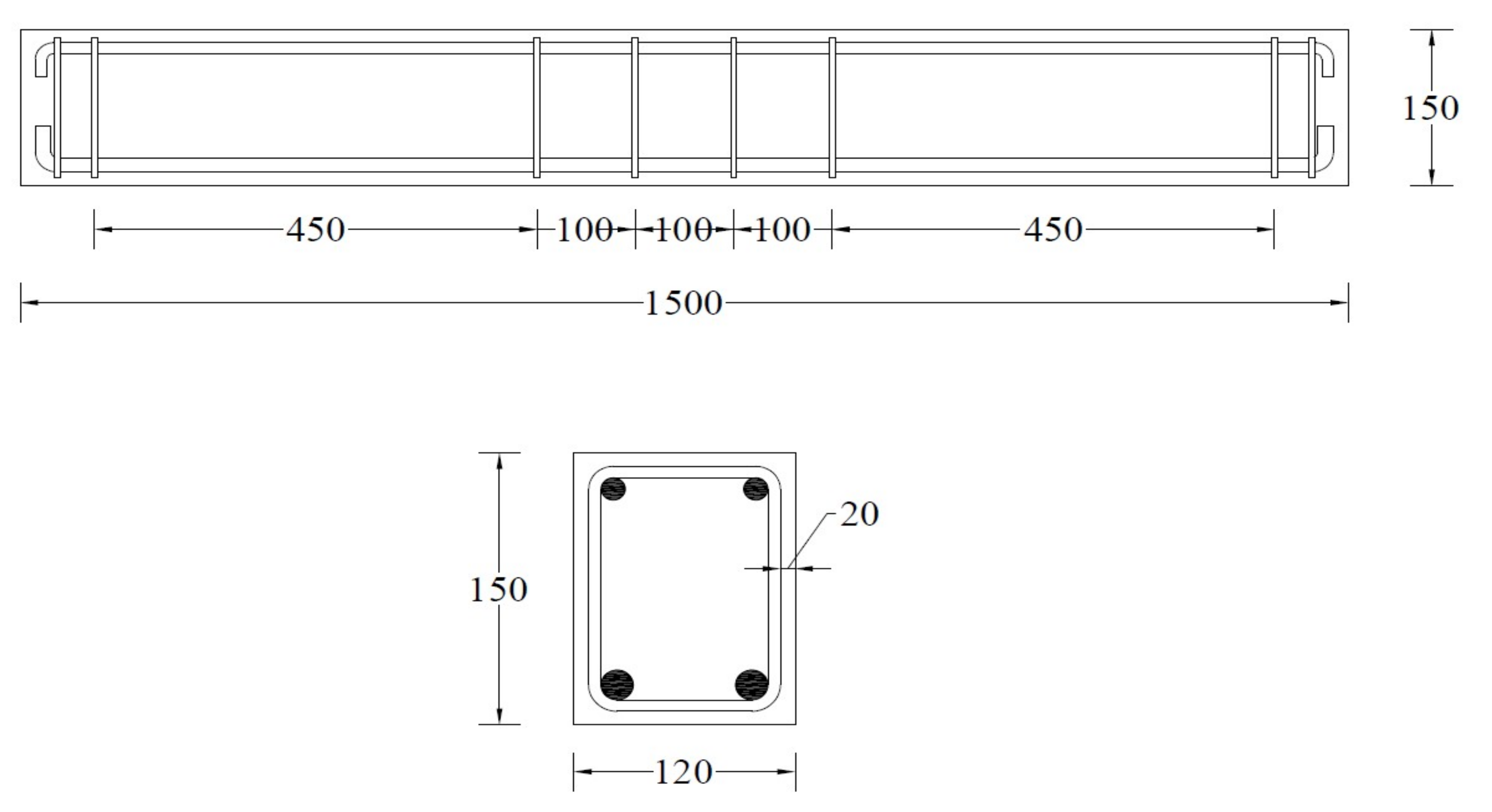
2.1. Details of RC Beams

In existing studies, RC beams without internal stirrups in shear dominant regions have been extensively tested to accurately assess the increase in the shear strength due to externally attached FRP composites [27,28]. Adhikary and Mutsuyoshi (2006) [29] used various techniques to enhance the shear strength of RC beams without internal stirrups. In their study, beams were designed to fail in shear. Four techniques, i.e., steel strips, stirrups, plates, and brackets, were used to strengthen RC beams. All of the techniques were observed to be useful in enhancing the ultimate load of RC beams. In another study, Bukhari et al., 2010 [30] performed tests on beams without internal stirrups. The beams were externally strengthened using CFRP strips. Dias and Barros (2005) also tested RC beams without internal stirrups and externally strengthened using near-surface mounted NSM CFRP strips [31]. The aim of the present research work was to study the contribution of externally wrapped natural fiber ropes in enhancing the shear strength of RC beams. Therefore, in this study, the RC beams were designed to fail in shear, and internal stirrups were omitted in the RC beams (Figure 1). However, to prevent concrete crushing at the loading region, stirrups were provided in the central 300 mm segment of the beam at a center-to-center distance of 100 mm, and stirrups were also provided at the ends of the beam, as shown in Figure 1. The total length, width, and depth of the RC beam were 1500 mm, 120 mm, and 150 mm, respectively. Deformed bars (DB) with 16 mm diameters were used for longitudinal tension steel bars. For compression longitudinal steel, deformed bars (DB) with 12 mm diameters were used. Round steel bars (RB) with a diameter of 6 mm were used for vertical stirrups. For the prevention of pull-out failure, proper anchorage was provided to the steel bars. The concrete cover was 20 mm.

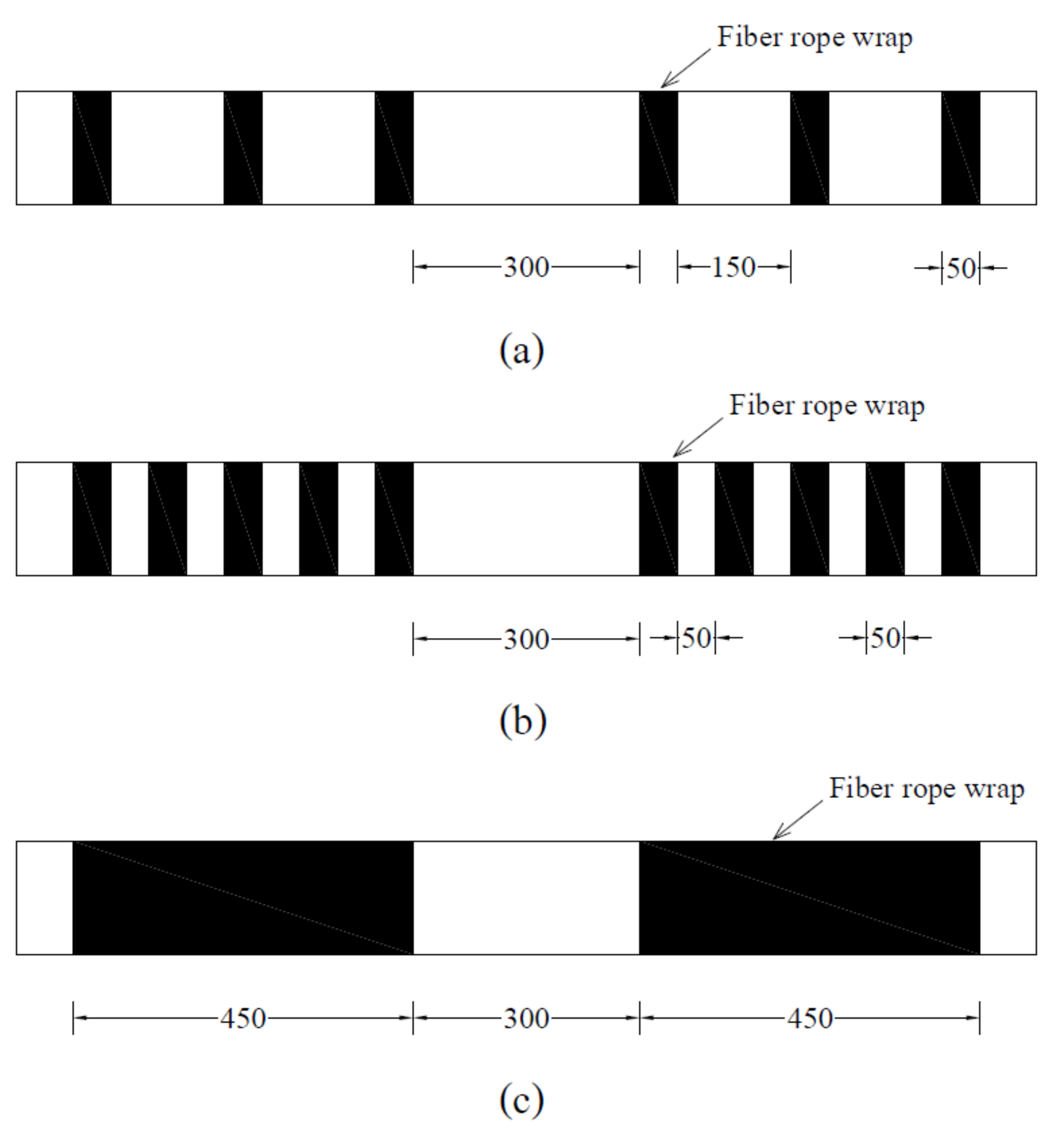
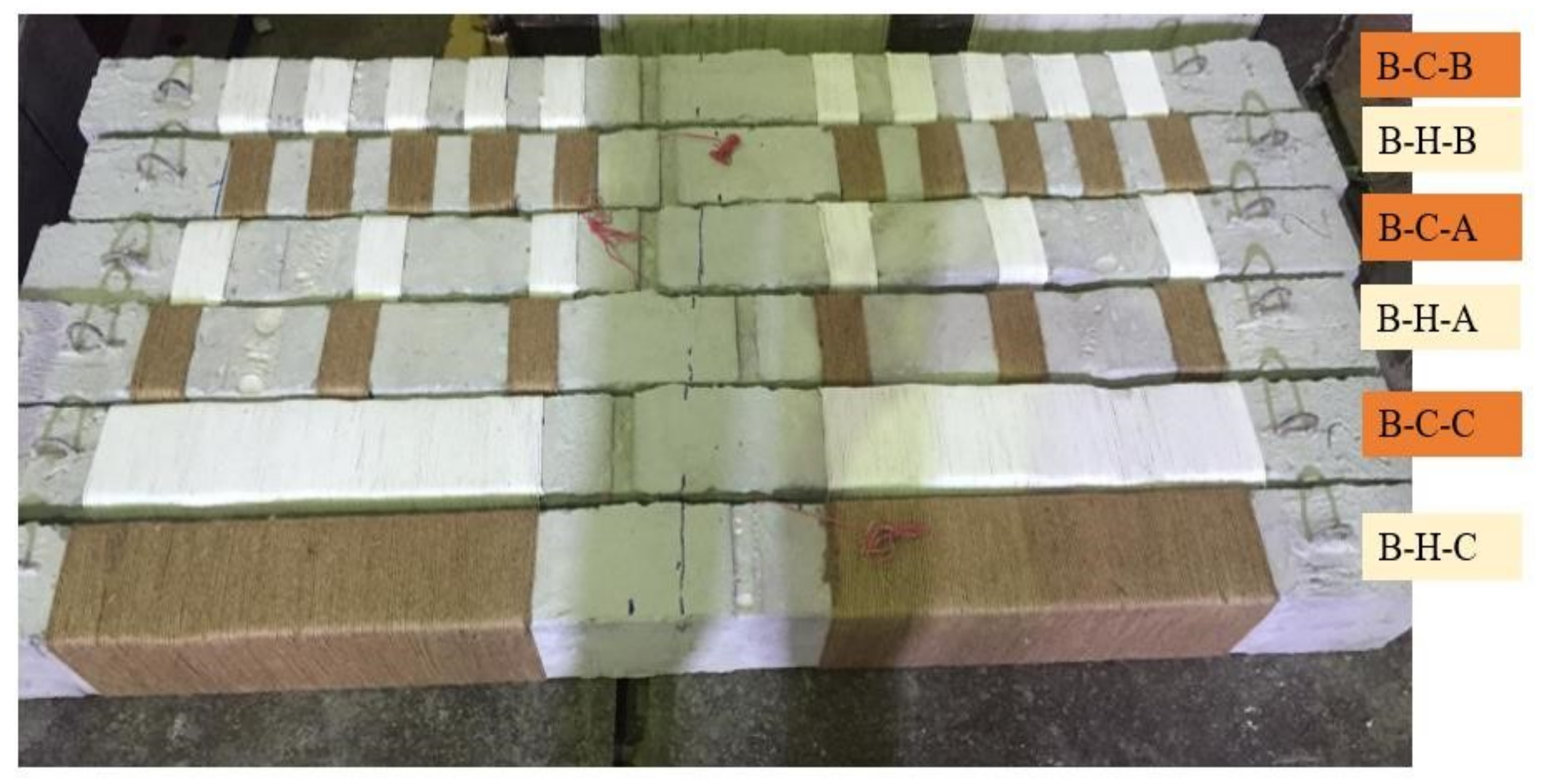
2.2. Details of Strengthening Using NFRRP Composites

In this study, a total of seven reinforced concrete beams were fabricated and strengthened using two different types of NFRRP composites (Table 1). The NFRRP composites were developed using natural hemp and cotton fiber ropes, as shown in Figure 2. The hemp fiber is more durable than the cotton fiber, and the human toxicity of the hemp fiber is lower than that of the cotton fiber. On the other hand, the water absorption capacity of the cotton fiber is lower than that of the hemp fiber. The hemp and cotton Fiber Rope Reinforced Polymer (FRRP) composites were applied in three different strengthening configurations, i.e., A, B, and C (Figure 3). In strengthening configuration A, the fiber ropes were wrapped to leave a gap of 150 mm after each 50 mm wrapping in the shear span region of the beam. In strengthening configuration B, fiber ropes were wrapped to leave a gap of 50 mm after each 50 mm wrapping in the shear span. In strengthening configuration C, the fiber ropes were wrapped in the shear span region. Two layers of NFRRP composites were applied for each configuration type. The beam specimen names are given in Table 1.

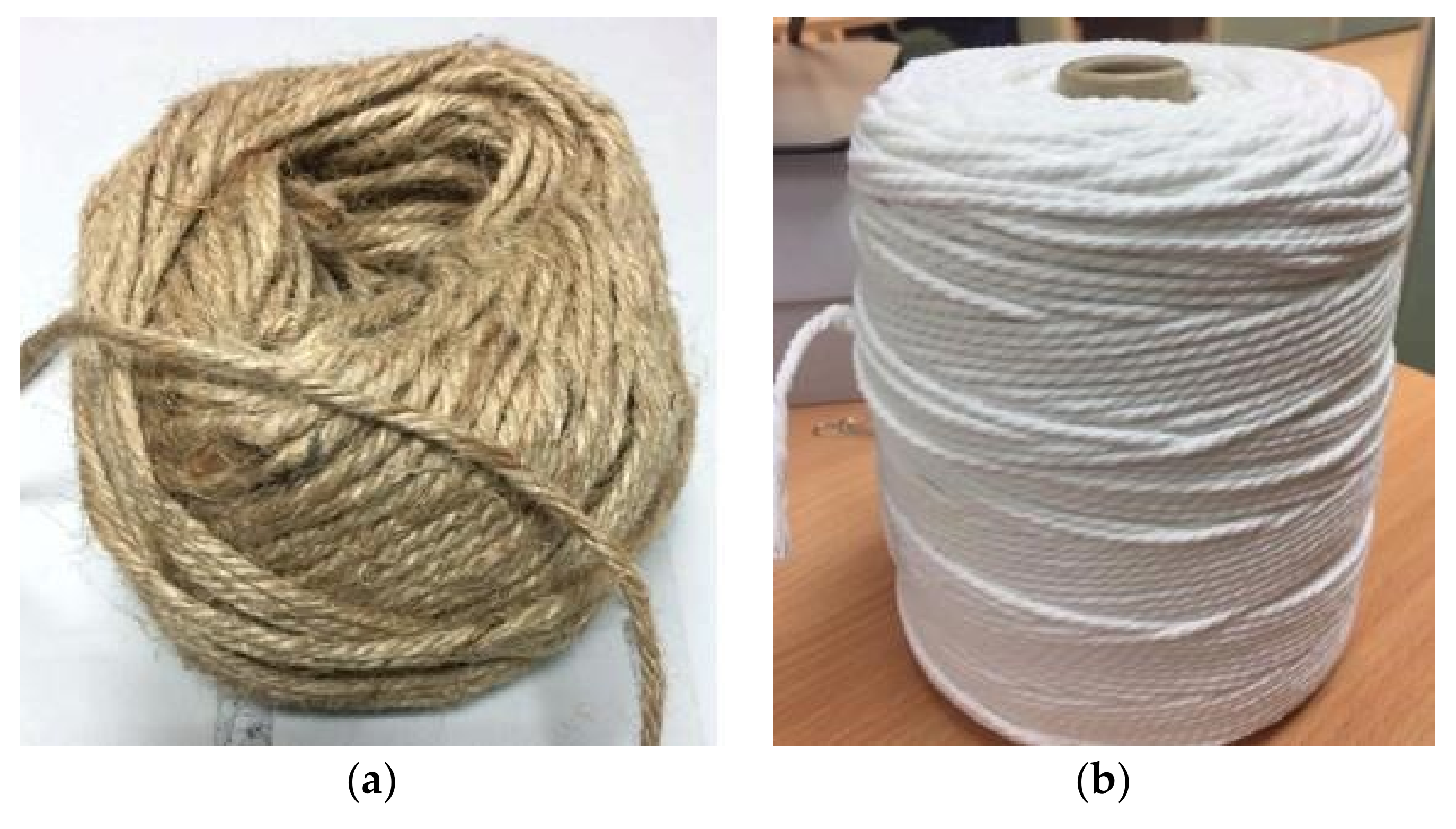
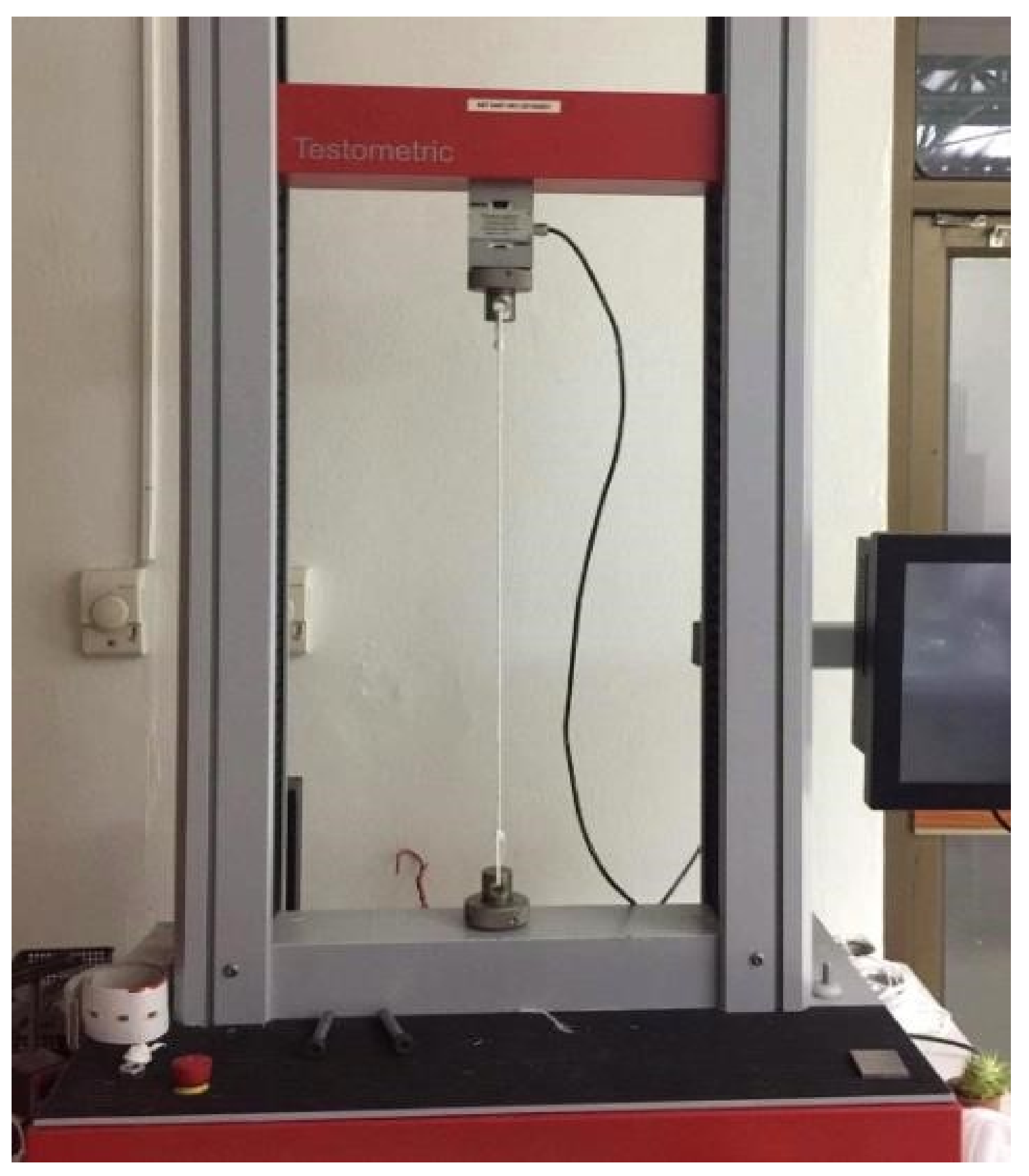
2.3. Details of Materials

The mix components of concrete are given in Table 2. Ordinary Portland Cement of Type 1 was used. Natural stones (coarse aggregates) with a size of 20–25 mm and natural river sand (fine aggregates) were used. The target compressive strength was 20 MPa, and on the day of testing, the actual achieved compressive strength was 18 MPa. Standard tensile tests were carried out to determine the stress-strain curves of all steel bars. All steel bars showed typical multilinear stress-strain behavior with elastic and plastic deformation. A typical stress-strain curve of steel bars is shown in Figure 4, and the tensile properties of steel bars are summarized in Table 3. Natural hemp and cotton fiber ropes were purchased from the local manufacturer. The diameters of the dry fiber hemp ropes and cotton fiber ropes were 2.4 and 2.8 mm, respectively. NFRRP composite was prepared by using available epoxy resin. The epoxy resin comprised two parts: resin and hardener. The mixing ratio of the resin and hardener was 2:1. The properties of the epoxy resin are shown in Table 4. The mechanical properties of the NFRRP composites, such as tensile strength and ultimate strain, were determined from the tensile tests on epoxy saturated hemp and cotton fiber ropes. The tensile tests were performed by using a M500-50AT computer-controlled materials universal testing machine, as shown in Figure 5. During the tensile tests, the displacement was increased at a constant speed of 1 mm/minute. The tensile stress-strain curve of hemp FRRP composite was linear, whereas the tensile stress-strain curve of cotton FRRP composite was bilinear. The typical stress-strain curves of hemp and cotton FRRP composites are shown in Figure 6, and the tensile properties are summarized in Table 5. Additional details of the stress-strain curves of hemp and cotton FRRP composites can be found in previous studies [25,26].

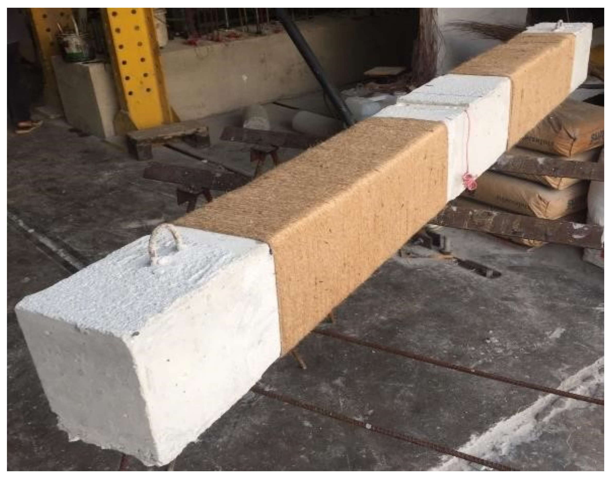
2.4. Preparation of RC Beams

The mixing of concrete was done using a mechanical mixer, and plywood formwork was used for the preparation of RC specimens. A typical reinforcement cage of RC beams is shown in Figure 7. The specimens were cured for a period of 7 days. In this research, super glue of high strength was employed to attach the ends of the rope fiber to the concrete, and the wrapping was done in such a way that there was no gap between fiber ropes. Once the first layer was finished, the epoxy resin was applied on the surface of fiber ropes with the help of a brush. Then, the NFRRP composite strengthened specimens were kept under ambient temperature for a period of 12 h. After this, the second layer was applied using the same technique that was employed for the first layer. Proper care was taken to ensure sufficiently tight wrapping. Figure 8 shows the beam having natural hemp ropes with configuration of type C. The fiber rope wrapped RC beams are shown in Figure 9.

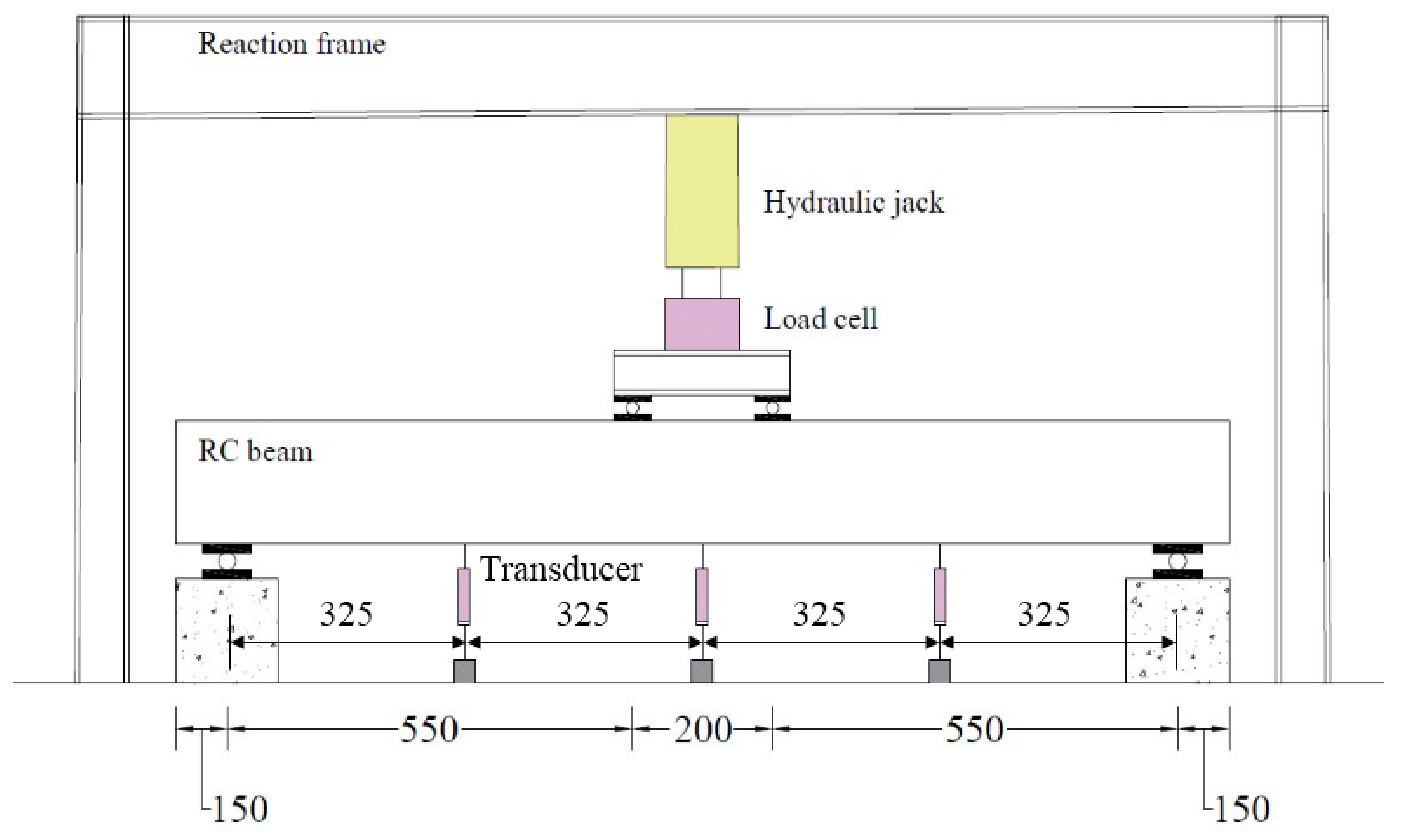
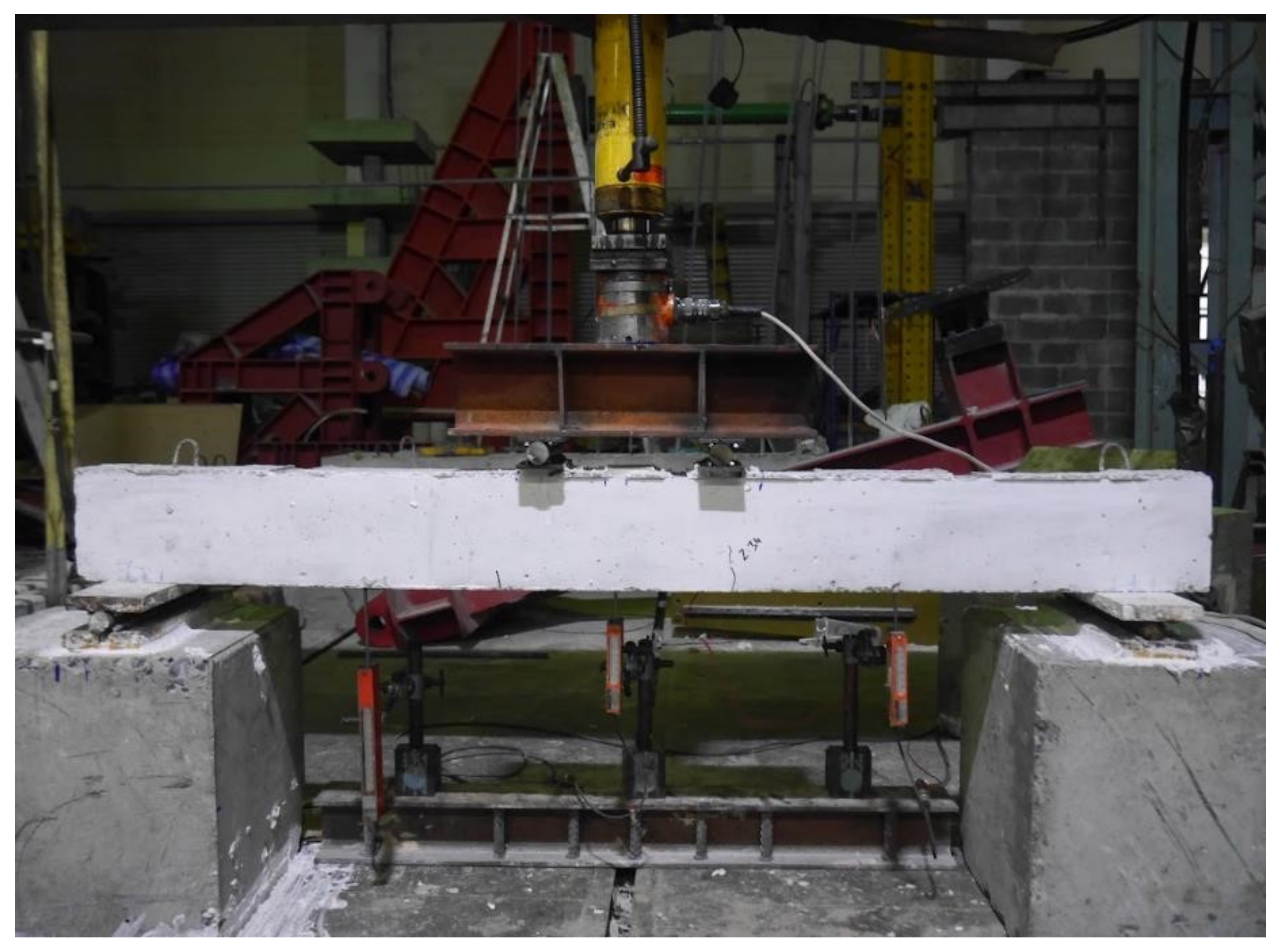
2.5. Instrumentation and Loading Setup

The RC beam under two-point loading is shown in Figure 10. The deflection of RC beams was recorded using displacement transducers. At the mid location of each tension steel bar, one strain gauge was also attached. The foil strain gauges by Tokyo Measuring Instruments Laboratory Co., Ltd. (Tokyo, Japan) were used in the test. The model number of the strain gauge was FLAB-5-11-1LJC-F. These strain gauges are capable of measuring the strain up to about 0.050 mm/mm according to the manufacturer’s specification. The capacities of the reaction frame, hydraulic jack, and load cell were 1500 kN, 600 kN, and 500 kN, respectively. The laboratory test setup is shown in Figure 11.

3. Results and Discussions

3.1. Ultimate Load and Deflection

The test results of the RC beams are summarized in Table 6. It can be seen that the contribution of NFRRP composites was significant in improving the shear strength of RC beams. Both the hemp and cotton fibers increased the ultimate load capacity of the beams. However, the performance of the hemp FRRP composite strengthened beams was better than that of the cotton FRRP composite strengthened beams. The hemp FRRP composite strengthened beams showed a larger increase in ultimate strength, and the percentage increase in ultimate strength was 63% for strengthening configuration C, while the similar configuration of the cotton FRRP composite strengthened beam showed a 56% increase in ultimate load capacity. Both types of fibers also improved the deflection of beams at ultimate load. It is clear from the Table 6 results that FRRP composite strengthened beams have much higher deflection capacity than the control beam. The highest percentage increase in deflection at ultimate load was shown by the beam B-C-A (185%), i.e., the cotton FRRP composite strengthened beam with configuration type A. The same configuration of the hemp FRRP (B-H-A 164%) beam also showed the highest increase in deflection at ultimate load among hemp FRRP beams. It is clear from Table 6 that all of the FRRP composite strengthened beams demonstrated higher strength and ductility as compared to the control beam.

3.2. Failure of RC Beams

Figure 12 shows the ultimate failure patterns of the RC beams. In the control beam (B-CON), the first crack was flexural, which occurred below the right loading point at the 2.34 kN load. When the load was increased to 2.95 kN, a new flexural crack was observed at the center point of beam. With further increase in the load, new cracks occurred, and the widening of existing cracks was also noticed. At the 4.4 kN load, shear cracks occurred in the control beam, and the beam was damaged due to shear failure. Zhang et al. (2004) [27] also reported this kind of shear failure behavior in the control beam, i.e., without shear reinforcement. In the hemp FRRP strengthened beam B-H-A, the first flexural crack was observed at the middle of the beam at the 3.80 kN load. This first cracking load was almost 62% higher than that of the control beam. With further increase in the load, shear cracks occurred within the right portion of the beam at 4.8 kN and 5 kN, as shown in Figure 12b. Shear cracks also occurred within the left portion near the beam support at 5.8 kN and 6.6 kN, and, ultimately, failure of beam occurred due to the cracking and crushing of concrete beneath the loading points. In hemp FRRP strengthened beams B-H-B and B-H-C, the first flexural crack was observed at 2.73 kN and 6.60 kN, respectively. The first cracking load of B-H-C was 141% higher than that of specimen B-H-B. At 3.6 kN, another flexural crack was observed in B-H-B, and the shear crack was observed at 6 kN at the right side of the beam. In the B-H-C beam, the second flexural crack was observed at 7.1 kN, which further propagated to form shear crack. A similar cracking pattern was also observed by Majumder and Saha (2021) [28]. The failure of both the B-H-B and B-H-C hemp FRRP strengthened beams was due to the crushing of concrete beneath the loading points.
In the cotton FRRP composite strengthened beam B-C-A, the first crack was also flexural at 3.03 kN in the middle of the beam. Shear cracks were observed at 4.4 kN and 4.6 kN. As the loading increased, more shear cracks were observed at 5 kN and 6.2 kN. The failure of this beam was due to the widening of the shear crack within the left side region near the loading position, which initially occurred at 4.6 kN, as can be seen in Figure 12e. In the cotton FRRP composite strengthened beams B-C-B and B-C-C, the first flexural crack was observed at the 3.68 kN and 5.10 kN loads, respectively. The first crack load of B-C-C was 39% higher than that of the B-C-B beam. At 4.9 kN, another flexural crack was observed in B-C-B, and then shear cracks were observed at 6.1 kN, 6.6 kN, and 6.9 kN in the right side of beam. As the loading was further increased, new flexural cracks were also observed at 7.06 kN. In the B-C-C beam, a second flexural crack was also observed, and then a shear crack was observed at the 6.6 kN load. The failure of the cotton FRRP composite strengthened beams B-C-B and B-C-C was due to the crushing of concrete beneath the loading points in the compression region of the beams.

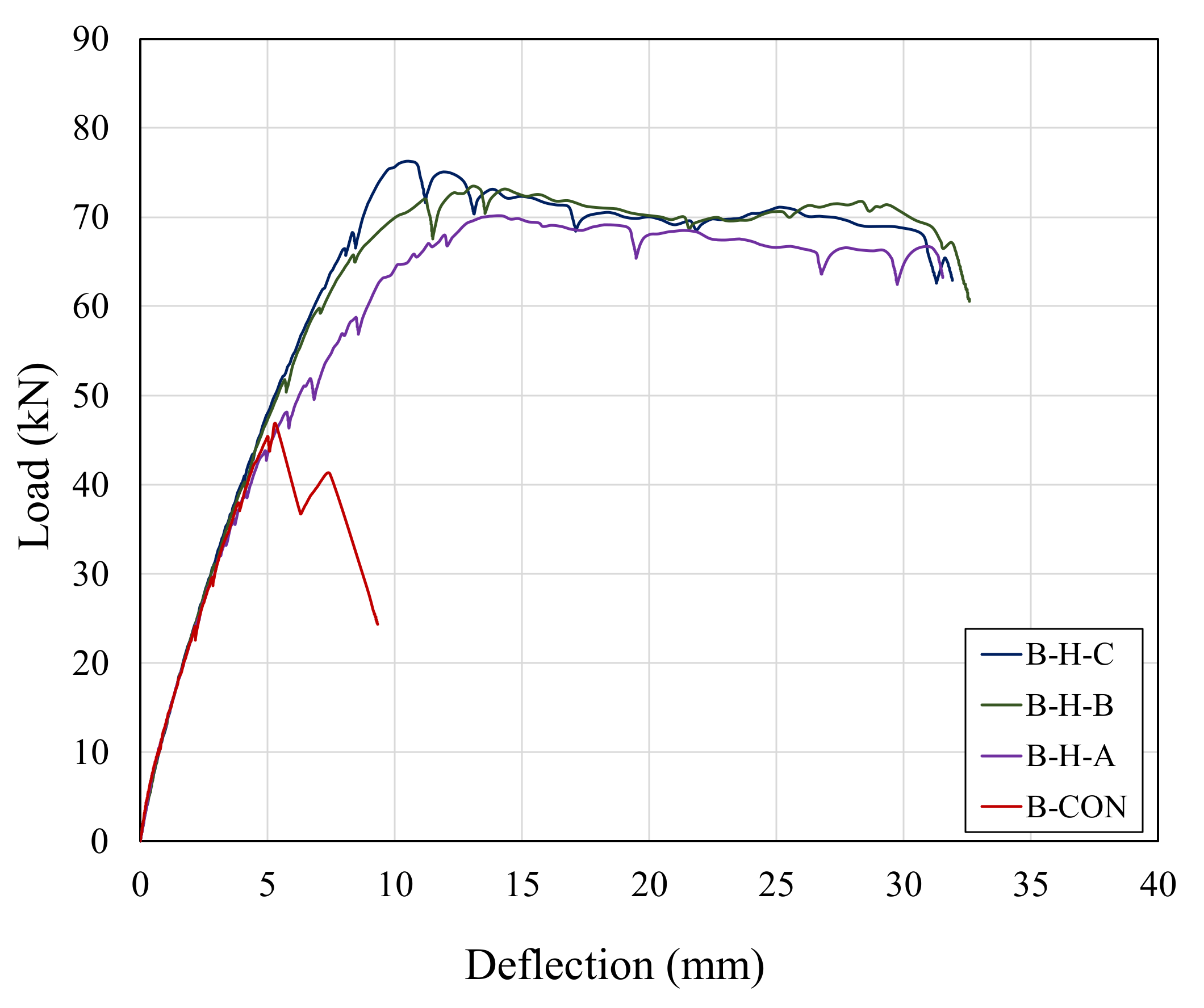
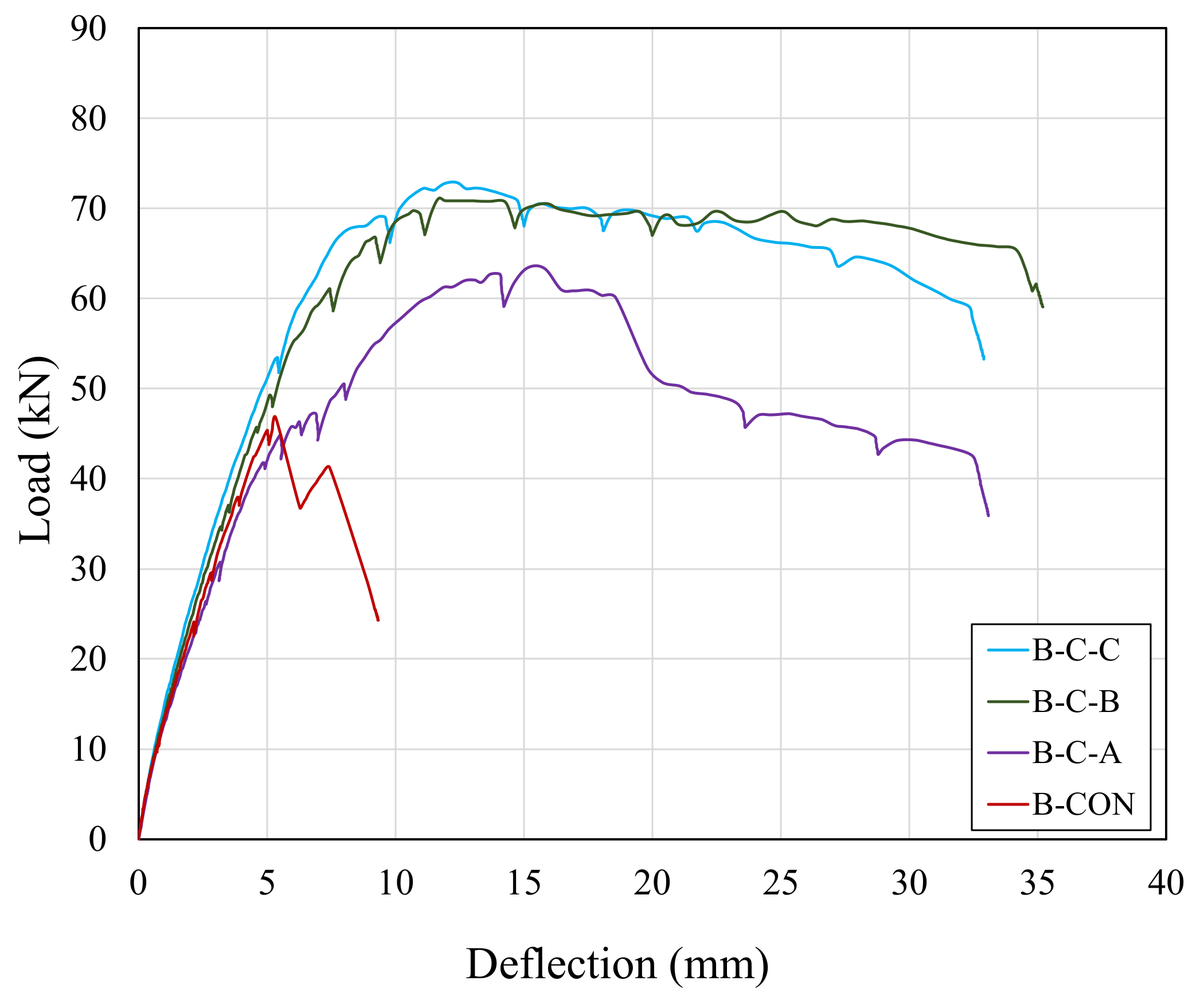
3.3. Load-Deflection Curves

The load-deflection curves for all beams, plotted in Figure 13 and Figure 14, show the superior performance of the FRRP composite strengthened beams when compared to the reference RC beam. It can be seen that the FRRP composite strengthened beams have higher ultimate load, higher deflection, and higher fracture load as compared to the reference beam. Furthermore, the reference beam showed a linear load-deflection curve until peak load and then failed suddenly after the peak load, indicating brittle shear failure, whereas the load-deflection curves of the hemp FRRP composite strengthened beams were linear until peak load and after that became almost stable, showing the flexural failure behavior (Figure 13). For the cotton FRRP composite strengthened beams, specimens B-C-B and B-C-C showed the same behavior as the hemp FRRP composite strengthened beams, i.e., flexure failure. On the other hand, beam specimen B-C-A showed different behavior from all other FRRP strengthened beams. From the graph of Figure 14 for the B-C-A beam, it can be seen that, after the stable portion of the curve, the load dropped suddenly, which indicates flexural-shear failure. This can be due to the bilinear material behavior of cotton fiber ropes, unlike the linear behavior of hemp fiber ropes. Furthermore, the cotton fibers rope also had less stiffness as compared to the hemp fiber rope, so this can also be the possible reason for the flexural-shear failure of specimen B-C-A. Since the FRRP strengthened beams exhibited flexural and flexural-shear failure, it was not possible to directly compare the shear strength capacity of the control and FRRP composite strengthened beams. However, the results confirm the important point that these FRRP fibers were useful, effective, and preferable because they protected RC shallow beams from shear failure and changed the failure modes to flexural and flexural-shear failure.

3.4. Energy Dissipation Capacity

In this study, the energy dissipation capacity was calculated using the area under the load-deflection curves. Table 7 shows the energy dissipation capacity of all tested specimens. From the test results, it can be seen that the energy dissipation capacities of both the hemp and cotton FRRP composite strengthened beams were considerably higher than that of the control beam. There was only a little effect of the strengthening configuration on the energy dissipation capacity of the hemp FRRP composite strengthened beams, while the cotton FRRP composite strengthened beams showed a greater effect of configuration. The percentage increases in the energy dissipation capacity of the cotton FRRP composite strengthened beams of type A, B, and C configurations were 441%, 642%, and 588%, respectively. Type B configuration for both the hemp and cotton FRRP composite strengthened beams performed better when compared to all other beams and showed an increase in energy dissipation capacity up to 596% and 642%, respectively. Hence, these FRRP composite strengthened beams considerably increased the energy dissipation capacity of beams.

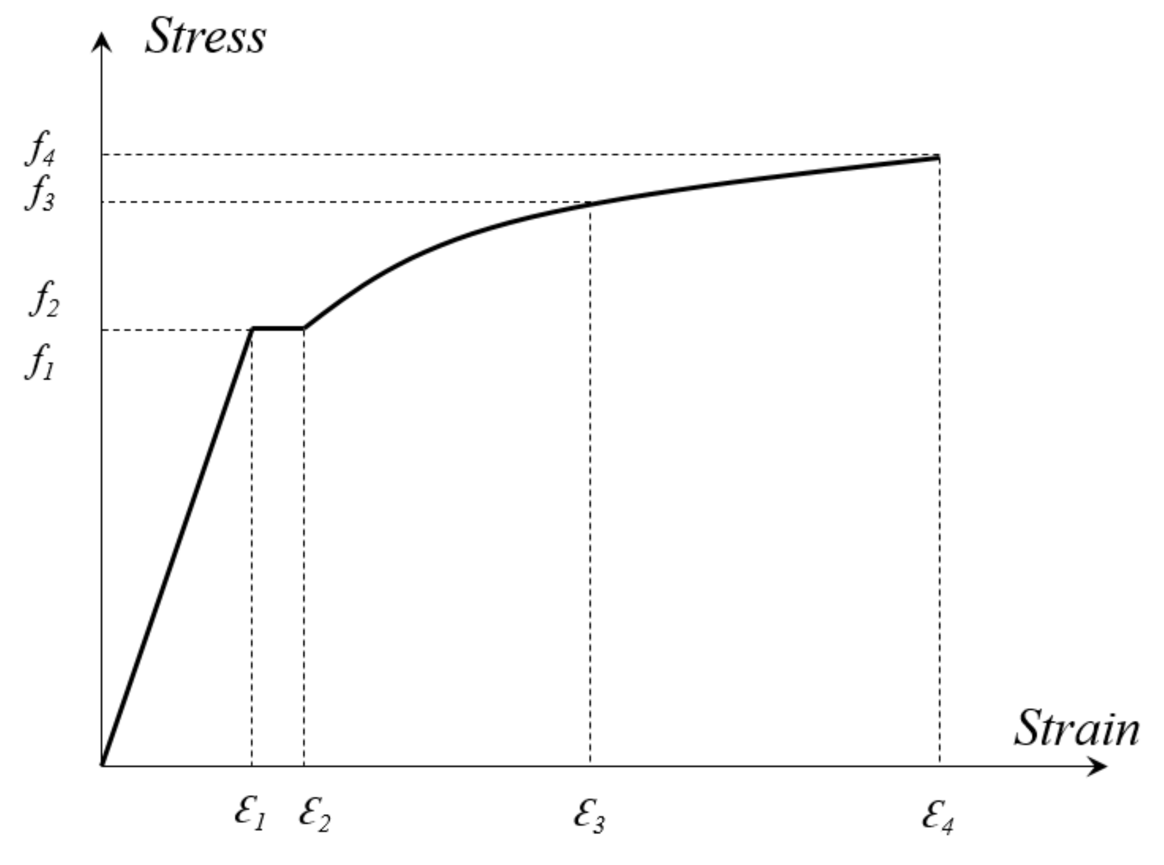
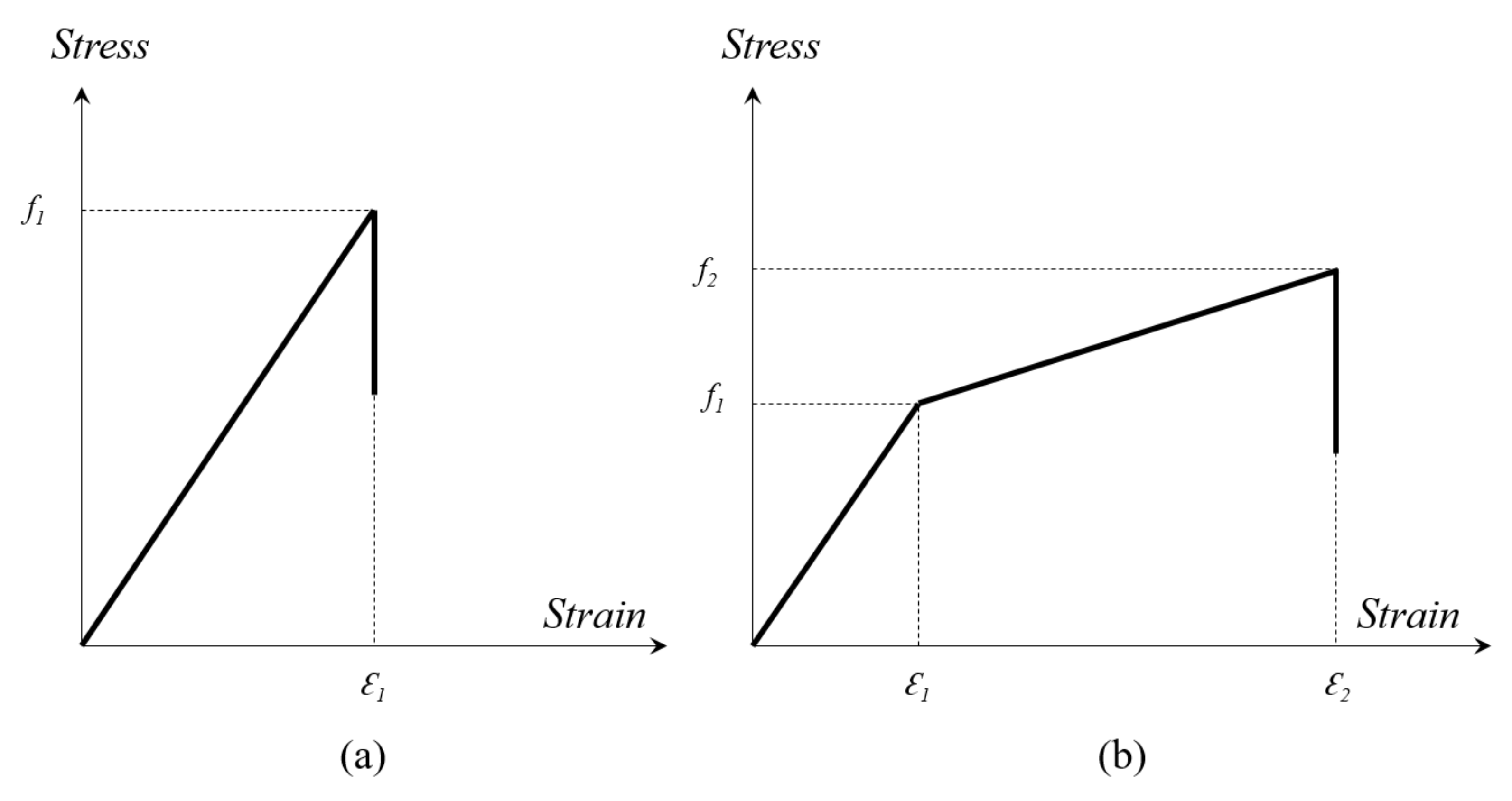
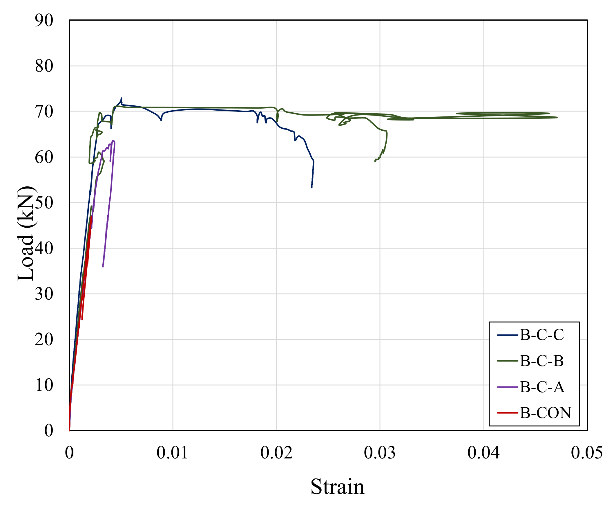
3.5. Tensile Behavior of Steel Bars

Table 8 shows the ultimate strain values of the tension steel bars of the specimens. The complete load-strain behavior of the tension steel bars of all beams is shown in Figure 15 and Figure 16. The maximum strain in the control beam was lower than the yield strain of steel. So, no yielding of steel occurred in the control beam. From Figure 15 and Figure 16 and Table 8, it can be seen that all of the FRRP strengthened beams had higher ultimate tensile strains when compared to the control beam, and these values were also larger than the yield strain. Hence, yielding of steel occurred in all the FRRP composite strengthened beams. Figure 15 shows that the hemp FRRP composite strengthened beams had almost the same tensile strain behavior for all three types of strengthened configurations. The percentage increase in the ultimate tensile strain in hemp FRRP types A, B, and C configurations were 1138%, 1103%, and 1079%, respectively. The cotton FRRP beams showed variation in the tensile strain behavior. The percentage increase in B-C-B was 2122%, which is the highest among all beams. The B-C-A, i.e., configuration type A, showed the lowest percentage increase in ultimate strain when compared to all other strengthened beams. The percentage increase in B-C-A was only 106%, while in B-C-C it was 1014%. All these results showed that there is a major increase in ultimate strain due to the confinement of beams using hemp and cotton FRRP composites.

3.6. Effect of Strengthening Configuration

As described in Section 2.2, the three fiber rope strengthening configuration types, A, B, and C, have total fiber rope wrap lengths of 300 mm, 500 mm, and 900 mm, respectively. From Table 6, it can be seen that the wrapping of beams increased the load carrying capacity of beams when compared to the control beam. For both the hemp and cotton FRRP composite strengthened beams, the larger the amount of wrapping on the beams, the greater the load carrying capacities of the beams. Type C configuration had a higher amount of load carrying capacity when compared to other configurations, because it had more of the span covered with the fiber ropes, which ultimately increased its performance. It can be seen that FRRP composites increased the deflection at ultimate load, but this deflection decreased as the wrap length increased (other than for specimen B-C-C). The cotton FRRP beam with configuration type A had the highest ultimate deflection, while the hemp FRRP beam with configuration type C had the lowest ultimate deflection as compared to all FRRP beams.

3.7. Effect of Type of NFRRP Composite

Table 6 showed that, for the same strengthening configurations of the hemp and cotton FRRP composite strengthened beams, the hemp FRRP composite strengthened beams demonstrated a higher load carrying capacity than that of the cotton FRRP composite strengthened beams, indicating that the hemp confined beams performed better in terms of load carrying capacities. The load carrying ability of the hemp FRRP beams was 11%, 4%, and 5% greater than that of the cotton FRRP beams for configuration types A, B, and C, respectively. The B-H-C beam had the highest load carrying capacity of 76.27 kN among all beams. On the other hand, the deflection of strengthening configuration types A and C of the cotton FRRP beams was greater than that of the hemp FRRP beams, whereas the deflection of configuration type B of the cotton FRRP beam was less than that of the hemp FRRP beam. The ultimate deflection data depicted that B-C-A has the highest ultimate deflection of 15.19 mm as compared to all other beams. Overall, the ultimate deflection performance of the cotton FRRP composite strengthened beams was much better than that of the hemp FRRP composite strengthened beams. The higher ultimate deflection of the FRRP composite strengthened beams could also be related to the ultimate failure modes of control and the FRRP strengthened RC beams. The ultimate failure modes of the FRRP composite strengthened beams were flexural and flexural-shear failure. As a result, the ultimate deflections of the FRRP composite strengthened beams were higher than that of the control beam.

4. Finite Element Analysis of NFRRP Composite Strengthened Beams

Nonlinear finite element analyses using ATENA software [32] were carried out to further check the detailed performance of NFRRP composites on the shear strengthening performance of shallow beams. Recently, Al-Abdwais et al. (2021) performed experimental and finite element analysis of RC beams strengthened using NSM with CFRP composites and cement adhesives. The experimental results were evaluated by using ATENA software. The authors reported a reasonable correlation of ultimate load and flexural stiffness between the experimental results and the finite element analysis [33]. In another study, Ruiz-Pinilla et al. conducted finite element modelling of iron-based shape memory alloy strengthened RC beams using ATENA software. The developed finite element models were able to reasonably predict the ultimate load and damage of RC beams [34].
The basic concept used in the ATENA finite element modeling in the present study is of smeared cracking [32,35]. The concrete was modelled using the basic built-in 8-node solid element CC3DNonLinCementitious2. The fracture concept of the concrete is based upon the uniaxial stress-strain law, as shown in Figure 17. The behavior of concrete in tension before cracking was assumed to be linear elastic. For tension after cracking, a fictitious crack model is used, which is based on a crack-opening law and fracture energy. The formula recommended by the CEB-FIP Model Code 2010 [36] was adopted for the ascending branch of the concrete stress versus strain law in compression. The global element size was considered as 0.015 m to model RC beams. The total number of 3D elements was 4500. The constitutive model used for steel bars in ATENA was a multilinear curve, as shown in Figure 4. This curve permits the modelling of different stages of steel behavior such as the elastic stage, yielding, strain hardening, and ultimate fracture [35]. The longitudinal steel and vertical stirrups were modelled using the built-in truss element CCReinforcement. A perfect bond was assumed between the steel bars and concrete. The built-in material “3D Elastic Istotropic” was adopted to model FRRP composites using an intensive modelling approach. The modelling approach has been also used in the previous studies to model the CFRP composites [37]. Figure 6 shows the constitutive models for hemp rope and cotton rope, similar to the models adopted by Hussain and Pimanmas (2015) [38]. Since de-bonding of the hemp and cotton ropes was not observed, the hemp and cotton ropes were therefore simulated with an assumption of perfect bond to concrete. The input parameters of CCReinforcement, hemp FRRP composites, and cotton FRRP composites in ATENA are given in Table 4 and Table 5. These input parameters were derived from the mechanical properties of steel bars and FRRP composites. In FEA, a linear-elastic approach was used to model steel plates at the support and loading point.
Typical finite element model geometry is shown in Figure 18a. A finite element model with reinforcement detail is shown in Figure 18b. The Newton–Raphson standard solver was used [35]. A displacement-controlled loading was applied at the prescribed load location. Because the beam was symmetric throughout, the model analysis on the half beam was done using boundary conditions along the beam symmetry line. Typical finite element models of RC beams with NFRRP configurations A, B, and C are shown in Figure 19.

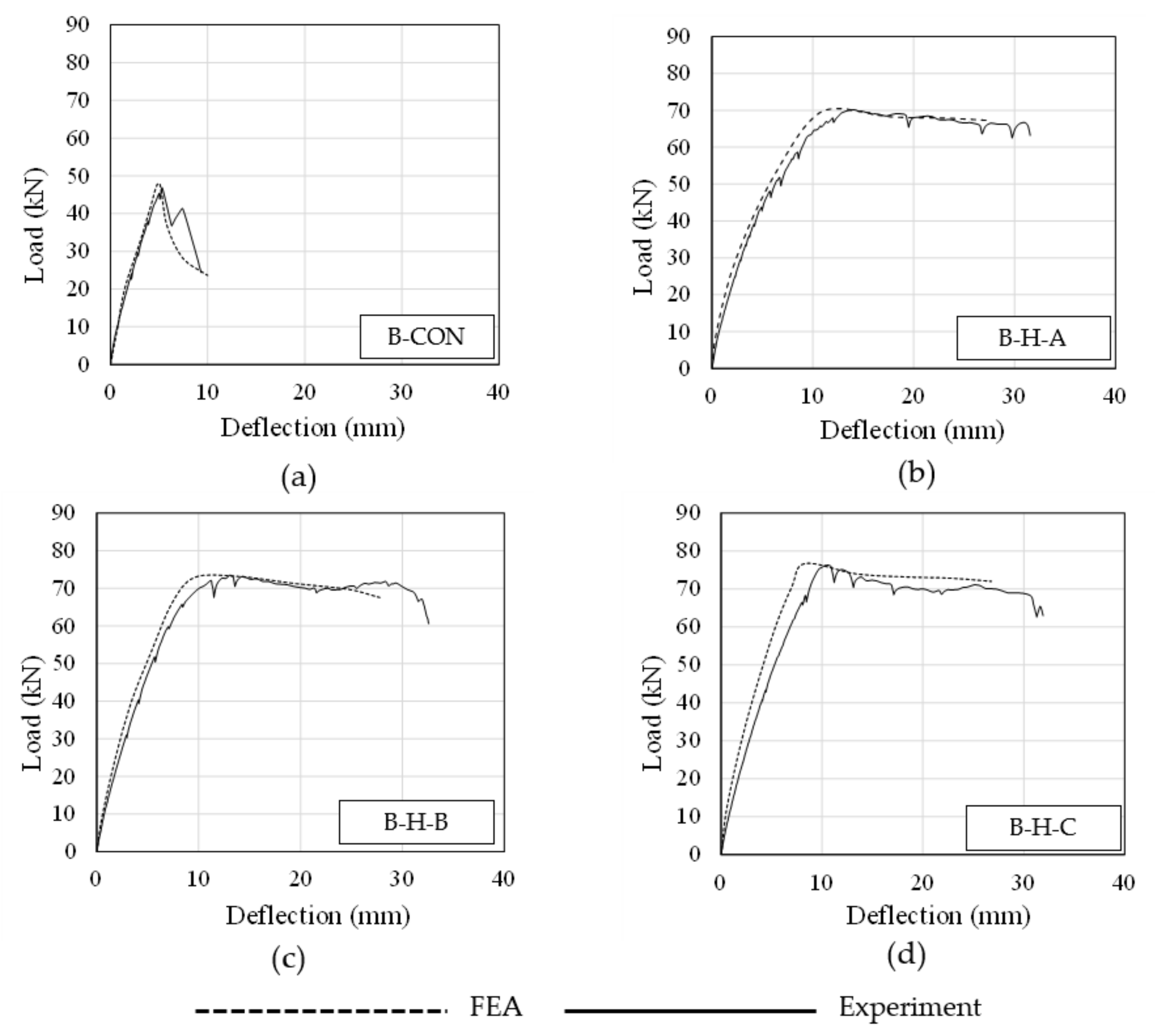
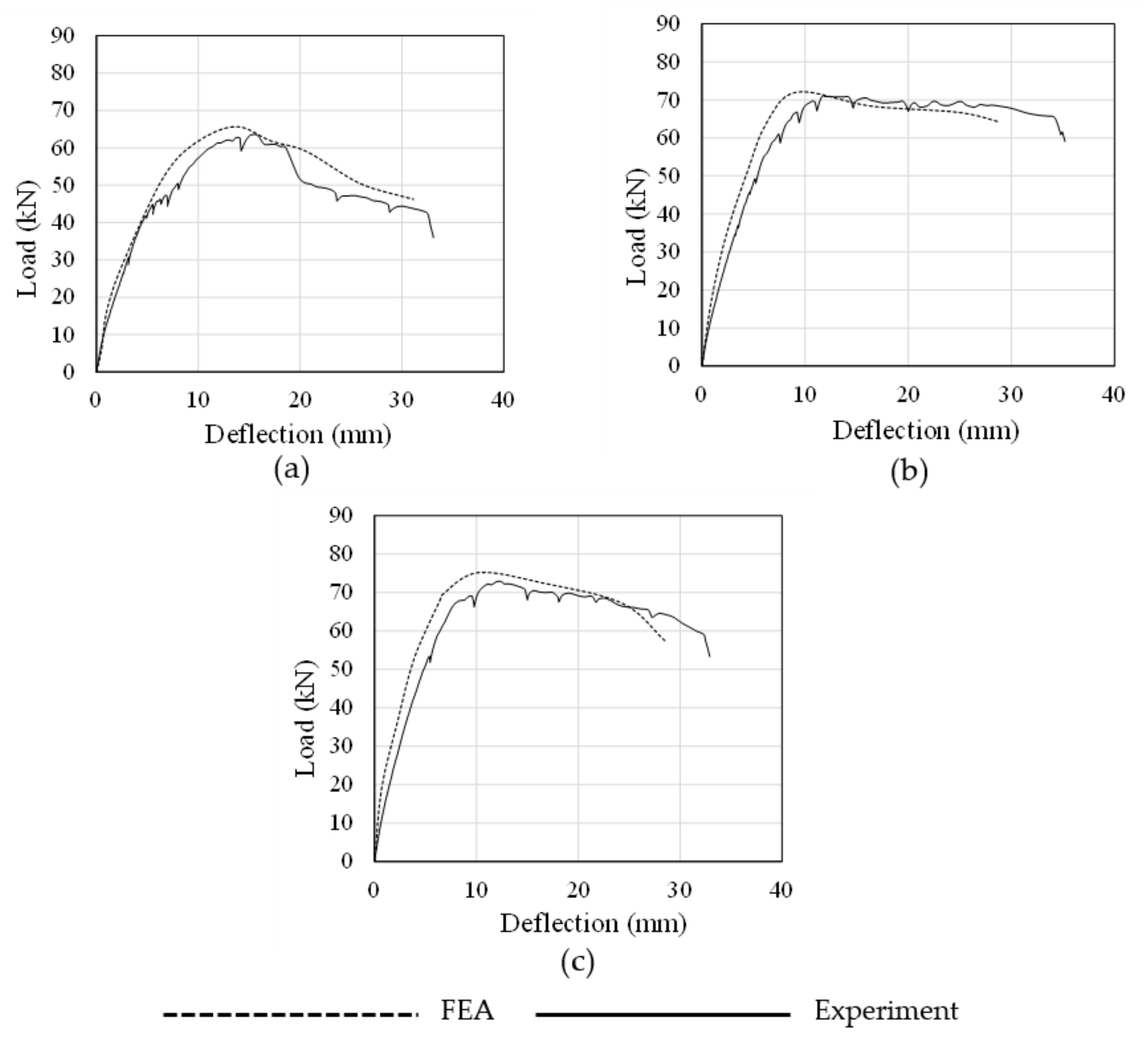
4.1. Comparison of Ultimate Load and Deflection

The comparison of the finite element analysis results with the experimental results is summarized in Table 9 and graphically shown in Figure 20 and Figure 21. It can be seen that FEA was able to predict the ultimate load carrying capacity as well as the deflection of the control and strengthened beams. The predicted ultimate load carrying values were almost 2–4% greater than the experimental values, whereas the predicted deflection values were 6–22% lower than the corresponding experimental deflection values. These results showed that the analytical results matched well with the experimental results of the control and NFRRP composite strengthened RC beams. In the case of the control beam (B-CON), the drop in the ultimate load carrying capacity was mainly due to the shear cracks in the shear failure region of the beam. Previous studies also reported that the built-in constitutive models of ATENA are able to accurately predict the ultimate load and deflections of shear dominated RC beams [33,39,40,41]. In the case of the NFRRP composite strengthened RC beams, the ultimate failure of these beams was mainly due to yielding of the longitudinal steel bars. As a result, the ATENA built-in material models predicted the behavior of the NFRRP composite strengthened RC beams well. However, the predicted initial stiffness was found to be higher than the experimental results of the NFRRP composite strengthened RC beams. This phenomenon could be associated with the unseen errors related to the installation of the RC beams and the test procedure.

4.2. Cracking and Ultimate Failure Modes

The predicted cracking pattern and failure modes of the control and FRRP beams for all the strengthened configurations are shown in Figure 22. The predicted cracking patterns were plotted using two types of built-in contours in ATNEA, i.e., (1) iso-area crack width in nodes and (2) element cracks. The experimental and FEM analysis results showed that the control beam had large diagonal shear cracks in the shear span. Moreover, the strengthened FRRP composite strengthened beams also showed the same flexural and flexural-shear cracking pattern in the predicted results as in the experimental results. These results showed a good matching of cracking pattern between the predicted and experimental results for the control as well as for the NFRRP composite strengthened beams.

5. Conclusions

This research work experimentally investigated the behavior of the shear strengthening of RC beams using natural fiber ropes, and finite element analysis was also carried out using ATENA software. From the experimental results and analytical analysis, the following conclusions can be drawn:
  • Epoxy bonded natural fiber ropes are very beneficial and effective in increasing the shear strength, deformation capacity, and energy dissipation capacity of RC beams.
  • The ultimate load carrying capacities of the hemp FRRP composite strengthened beams B-H-A, B-H-B, and B-H-C were 50%, 57%, and 63% higher than that of the control beam, whereas the ultimate load carrying capacities of the cotton FRRP composite strengthened beams B-C-A, B-C-B, and B-C-C were 36%, 52%, and 56% higher than that of the control beam.
  • Type C configuration had highest amount of load carrying capacity when compared to other configurations, whereas type A configuration for both the hemp and cotton fibers performed the best in deflection as compared to other configurations.
  • The load carrying capacities of the hemp FRRP composite strengthened beams were greater than those of the cotton FRRP composite strengthened beams for all types of strengthening configurations, whereas the ultimate deflection performance of the cotton FRRP composite strengthened beams was much better than that of the hemp FRRP composite strengthened beams. The load carrying capacities of the hemp FRRP composite strengthened beams were 11%, 4%, and 5% greater than those of the cotton FRRP composite strengthened beams for configuration types A, B, and C, respectively. The ultimate deflection of the cotton FRRP composite strengthened beams was 11%, 4%, and 5% greater than that of the hemp FRRP composite strengthened beams for configuration types A, B, and C, respectively.
  • In terms of energy dissipation capacity, strengthening configuration type B for both types of natural fiber ropes was most effective when compared with other configurations.
  • These FRRP fibers are useful, effective, and preferable because they change the failure of beams from shear failure mode to flexural and flexural-shear failure mode.
  • FEM analysis was carried out, and the analytical results showed good comparison with the experimental results. The failure modes and cracking patterns of the FEM analysis were well matched with the experimental failure modes and cracking patterns.

Author Contributions

Conceptualization, Q.H., A.R. and P.J.; methodology, Q.H., A.R. and P.J.; validation, A.R. and A.C.W.; writing—original draft preparation, Q.H., A.R., P.J. and A.C.W.; writing—review and editing, Q.H., A.R., P.J. and A.C.W. All authors have read and agreed to the published version of the manuscript.

Funding

This research received no external funding.

Institutional Review Board Statement

Not applicable.

Informed Consent Statement

Not applicable.

Data Availability Statement

Not applicable.

Acknowledgments

This research project was supported by the Second Century Fund (C2F), Chulalongkorn University, Thailand. We also thank the Asian Institute of Technology (AIT), Thailand for supporting test facilities.

Conflicts of Interest

The authors declare no conflict of interest.

References

  1. Ascione, L.; Feo, L. Modeling of composite/concrete interface of RC beams strengthened with composite laminates. Compos. Part B Eng. 2000, 31, 535–540. [Google Scholar] [CrossRef]
  2. Sim, J.; Park, C.; Moon, D.Y. Characteristics of basalt fiber as a strengthening material for concrete structures. Compos. Part B Eng. 2005, 36, 504–512. [Google Scholar] [CrossRef]
  3. Yao, J.; Teng, J.; Chen, J.-F. Experimental study on FRP-to-concrete bonded joints. Compos. Part B Eng. 2004, 36, 99–113. [Google Scholar] [CrossRef]
  4. Katakalos, K.; Manos, G.; Papakonstantinou, C. Seismic Retrofit of R/C T-Beams with Steel Fiber Polymers under Cyclic Loading Conditions. Buildings 2019, 9, 101. [Google Scholar] [CrossRef] [Green Version]
  5. Khalifa, A.; Nanni, A. Improving shear capacity of existing RC T-section beams using CFRP composites. Cem. Concr. Compos. 2000, 22, 165–174. [Google Scholar] [CrossRef]
  6. Chen, J.-F.; Teng, J. Shear capacity of FRP-strengthened RC beams: FRP debonding. Constr. Build. Mater. 2002, 17, 27–41. [Google Scholar] [CrossRef]
  7. Chen, G.M.; Teng, J.G.; Chen, J.-F. Shear Strength Model for FRP-Strengthened RC Beams with Adverse FRP-Steel Interaction. J. Compos. Constr. 2013, 17, 50–66. [Google Scholar] [CrossRef]
  8. Triantafyllou, G.; Rousakis, T.; Karabinis, A. Corroded RC Beams at Service Load before and after Patch Repair and Strengthening with NSM CFRP Strips. Buildings 2019, 9, 67. [Google Scholar] [CrossRef] [Green Version]
  9. Santarsiero, G. FE Modelling of the Seismic Behavior of Wide Beam-Column Joints Strengthened with CFRP Systems. Buildings 2018, 8, 31. [Google Scholar] [CrossRef] [Green Version]
  10. Mhanna, H.H.; Hawileh, R.A.; Abdalla, J.A. Shear Strengthening of Reinforced Concrete Beams Using CFRP Wraps. Procedia Struct. Integr. 2019, 17, 214–221. [Google Scholar] [CrossRef]
  11. Chalioris, C.E.; Kytinou, V.K.; Voutetaki, M.E.; Papadopoulos, N.A. Repair of heavily damaged RC beams failing in shear using U-shaped mortar jackets. Buildings 2019, 9, 146. [Google Scholar] [CrossRef] [Green Version]
  12. Moradi, E.; Naderpour, H.; Kheyroddin, A. An experimental approach for shear strengthening of RC beams using a proposed technique by embedded through-section FRP sheets. Compos. Struct. 2020, 238, 111988. [Google Scholar] [CrossRef]
  13. Dias, S.; Silva, J.; Barros, J. Flexural and shear strengthening of reinforced concrete beams with a hybrid CFRP solution. Compos. Struct. 2020, 256, 113004. [Google Scholar] [CrossRef]
  14. Malek, A.M.; Saadatmanesh, H. Ultimate shear capacity of reinforced concrete beams strengthened with web-bonded fiber-reinforced plastic plates. ACI Struct. J. 1998, 95, 391–399. [Google Scholar]
  15. Triantafillou, T.C. Shear strengthening of reinforced concrete beams using epoxy-bonded FRP composites. ACI Struct. J. 1998, 95, 107–115. [Google Scholar]
  16. Yang, X.; Gao, W.-Y.; Dai, J.-G.; Lu, Z.-D.; Yu, K. Flexural strengthening of RC beams with CFRP grid-reinforced ECC matrix. Compos. Struct. 2018, 189, 9–26. [Google Scholar] [CrossRef]
  17. Jirawattanasomkul, T.; Kongwang, N.; Jongvivatsakul, P.; Likitlersuang, S. Finite element modelling of flexural behaviour of geosynthetic cementitious composite mat (GCCM). Compos. Part B Eng. 2018, 154, 33–42. [Google Scholar] [CrossRef]
  18. Jirawattanasomkul, T.; Kongwang, N.; Jongvivatsakul, P.; Likitlersuang, S. Finite element analysis of tensile and puncture behaviours of geosynthetic cementitious composite mat (GCCM). Compos. Part B Eng. 2019, 165, 702–711. [Google Scholar] [CrossRef]
  19. Wakjira, T.G.; Ebead, U. Hybrid NSE/EB technique for shear strengthening of reinforced concrete beams using FRCM: Experimental study. Constr. Build. Mater. 2018, 164, 164–177. [Google Scholar] [CrossRef]
  20. Wambua, P.; Ivens, J.; Verpoest, I. Natural fibres: Can they replace glass in fibre reinforced plastics? Compos. Sci. Technol. 2003, 63, 1259–1264. [Google Scholar] [CrossRef]
  21. Alam, M.; Hassan, A.; Muda, Z.C. Development of kenaf fibre reinforced polymer laminate for shear strengthening of reinforced concrete beam. Mater. Struct. 2016, 49, 795–811. [Google Scholar] [CrossRef]
  22. Horsangchai, K.; Jirawattanasomkul, T.; Ueda, T. Behavior of concrete confined with jute and hemp natural fiber reinforced polymer. In Proceedings of the 8th International Conference on Fibre-Reinforced Polymer (FRP) Composites in Civil Engineering (CICE 2016), Hong Kong, China, 14–16 December 2016. [Google Scholar]
  23. Bambach, M. Compression strength of natural fibre composite plates and sections of flax, jute and hemp. Thin-Walled Struct. 2017, 119, 103–113. [Google Scholar] [CrossRef]
  24. Alam, M.A.; Al Riyami, K. Shear strengthening of reinforced concrete beam using natural fibre reinforced polymer laminates. Constr. Build. Mater. 2018, 162, 683–696. [Google Scholar] [CrossRef]
  25. Hussain, Q.; Ruangrassamee, A.; Tangtermsirikul, S.; Joyklad, P. Behavior of concrete confined with epoxy bonded fiber ropes under axial load. Constr. Build. Mater. 2020, 263, 120093. [Google Scholar] [CrossRef]
  26. Hussain, Q.; Ruangrassamee, A.; Tangtermsirikul, S.; Joyklad, P.; Wijeyewickrema, A.C. Low-Cost Fiber Rope Reinforced Polymer (FRRP) Confinement of Square Columns with Different Corner Radii. Buildings 2021, 11, 355. [Google Scholar] [CrossRef]
  27. Zhang, Z.; Hsu, C.T.T.; Moren, J. Shear strengthening of reinforced concrete deep beams using carbon fiber reinforced polymer laminates. J. Compos. Constr. 2004, 8, 403–414. [Google Scholar] [CrossRef]
  28. Majumder, S.; Saha, S. Shear behaviour of RC beams strengthened using geosynthetic materials by external and internal confinement. Structures 2021, 32, 1665–1678. [Google Scholar] [CrossRef]
  29. Adhikary, B.B.; Mutsuyoshi, H. Shear strengthening of reinforced concrete beams using various techniques. Constr. Build. Mater. 2006, 20, 366–373. [Google Scholar] [CrossRef]
  30. Bukhari, I.; Vollum, R.; Ahmad, S.; Sagaseta, J. Shear strengthening of reinforced concrete beams with CFRP. Mag. Concr. Res. 2010, 62, 65–77. [Google Scholar] [CrossRef] [Green Version]
  31. Dias, S.J.; Barros, J.A. Shear Strengthening of RC Beams with Near-Surface-Mounted CFRP Laminates; American Concrete Institute: Farmington Hills, MI, USA, 2005. [Google Scholar]
  32. Pukl, R.; Cervenka, J.; Cervenka, V. Simulating a response of connections. In Proceedings of the RILEM Symposium on Connections between Steel and Concrete, Stuttgart, Germany, 10–12 September 2001. [Google Scholar]
  33. Al-Abdwais, A.H.; Al-Mahaidi, R.S. Experimental and finite element analysis of flexural performance of RC beams retrofitted using near-surface mounted with CFRP composites and cement adhesive. Eng. Struct. 2021, 241, 112429. [Google Scholar] [CrossRef]
  34. Ruiz-Pinilla, J.G.; Montoya-Coronado, L.A.; Ribas, C.; Cladera, A. Finite element modeling of RC beams externally strengthened with iron-based shape memory alloy (Fe-SMA) strips, including analytical stress-strain curves for Fe-SMA. Eng. Struct. 2020, 223, 111152. [Google Scholar] [CrossRef]
  35. Červenka, V.; Jendele, L.; Červenka, J. ATENA Program Documentation–Part 1; Cervenka Consulting Sro: Prague, Czech Republic, 2000. [Google Scholar]
  36. MC10. CEB-FIP Model Code. In Bulletin d’Information No. 65/66; Comité Euro-International Du Béton Lausanne: Lausanne, Switzerland, 2010.
  37. Gambarelli, S.; Ožbolt, J. MESO-Scale Modeling of CFRP-Confined Concrete: Microplane-Based Approach. Fibers 2020, 8, 38. [Google Scholar] [CrossRef]
  38. Hussain, Q.; Pimanmas, A. Shear strengthening of RC deep beams with sprayed fiber-reinforced polymer composites (SFRP): Part 2 Finite element analysis. Lat. Am. J. Solids Struct. 2015, 12, 1266–1295. [Google Scholar] [CrossRef]
  39. Kannam, P.; Sarella, V.R. A study on validation of shear behaviour of steel fibrous SCC based on numerical modelling (ATENA). J. Build. Eng. 2018, 19, 69–79. [Google Scholar] [CrossRef]
  40. Shaaban, I.G.; Said, M.; Khan, S.U.; Eissa, M.; Elrashidy, K. Experimental and theoretical behaviour of reinforced concrete beams containing hybrid fibres. Structures 2021, 32, 2143–2160. [Google Scholar] [CrossRef]
  41. Malm, R.; Holmgren, J. Cracking in deep beams owing to shear loading. Part 2: Non-linear analysis. Mag. Concr. Res. 2008, 60, 381–388. [Google Scholar] [CrossRef]
Figure 1. Typical details of RC beams (all dimensions in mm).
Buildings 12 00602 g001
Figure 2. Natural fiber ropes (a) hemp and (b) cotton.
Buildings 12 00602 g002
Figure 3. Strengthening configurations (a) Type A, (b) Type B, and (c) Type C (all dimensions in mm).
Buildings 12 00602 g003
Figure 4. Typical stress-strain curve of steel bars.
Buildings 12 00602 g004
Figure 5. Typical tensile test setup for NFRRP composites.
Buildings 12 00602 g005
Figure 6. Typical stress-strain curves of FRRP composites (a) hemp and (b) cotton.
Buildings 12 00602 g006
Figure 7. Typical view of steel bars.
Buildings 12 00602 g007
Figure 8. RC beam with strengthening configuration type C natural hemp ropes.
Buildings 12 00602 g008
Figure 9. RC beams with different strengthening configurations.
Buildings 12 00602 g009
Figure 10. Typical loading setup (all dimensions in mm).
Buildings 12 00602 g010
Figure 11. Laboratory test setup.
Buildings 12 00602 g011
Figure 12. Failure patterns of RC beams (a) B-CON, (b) B-H-A, (c) B-H-B, (d) B-H-C, (e) B-C-A, (f) B-C-B, (g) B-C-C.
Buildings 12 00602 g012
Figure 13. Load-deflection curves of the control and hemp FRRP composite strengthened beams.
Buildings 12 00602 g013
Figure 14. Load-deflection curves of control and cotton FRRP composite strengthened beams.
Buildings 12 00602 g014
Figure 15. Load-strain curves of control and hemp FRRP strengthened beams.
Buildings 12 00602 g015
Figure 16. Load-strain curves of control and cotton FRRP strengthened beams.
Buildings 12 00602 g016
Figure 17. Uniaxial stress versus strain law for concrete (fc = 18 MPa, ft = 2.29 MPa, Ec = 19.94 GPa, εc1 = 0.0034, εc2 = 0.0048).
Buildings 12 00602 g017
Figure 18. Typical FEM of RC beams using ATENA (a) geometry and (b) steel bars.
Buildings 12 00602 g018
Figure 19. Finite element modelling of NFRRP composite strengthened RC beams (a) Type A configuration, (b) Type B configuration, (c) Type C configuration.
Buildings 12 00602 g019
Figure 20. Load deflection curves of control and hemp FRRP composite strengthened beams (a) B-CON, (b) B-H-A, (c) B-H-B, (d) B-H-C.
Buildings 12 00602 g020
Figure 21. Load deflection curves of control and cotton FRRP composite strengthened beams (a) B-C-A, (b) B-C-B, (c) B-C-C.
Buildings 12 00602 g021
Figure 22. Comparison of finite element analysis cracking patterns versus experimental cracking patterns (a) B-CON, (b) B-H-A, (c) B-H-B, (d) B-H-C, (e) B-C-A, (f) B-C-B, (g) B-C-C.
Buildings 12 00602 g022
Table 1. Beam specimen designation.
SpecimenFiber RopeStrengthening Configuration
B-CON--
B-H-AHempA
B-H-BHempB
B-H-CHempC
B-C-ACottonA
B-C-BCottonB
B-C-CCottonC
Table 2. Mix Components of Concrete.
ComponentsQuantity (kg/m3)
Water259
Cement (Ordinary Portland Type-1)279
Stones (coarse aggregates)1035
Sand (fine aggregates)828
Table 3. Mechanical properties of steel bars.
Steel BarsStrength (MPa)Strain (mm/mm)
f1f2f3f4ε1ε2ε3ε4
DB164504705155600.00250.00440.01000.0169
DB124204254705300.00260.00460.01000.0158
RB63503504154800.00220.00380.00850.0141
Table 4. Properties of epoxy resin.
Curing time7–10 h
Tensile strength45 MPa
Flexural strength65 MPa
Table 5. Mechanical properties of NFRRP composites.
FRRP CompositesStrength (MPa) Strain (mm/mm)
f1f2ε1ε2
Hemp177-0.0023-
Cotton801290.00250.0129
Table 6. Ultimate load and deflection of control and FRRP strengthened RC beams.
SpecimenLoad at First Crack (kN)Load at First Yield (kN)Deflection at First Yield (mm)Ultimate Load(kN)% Increase in Ultimate LoadDeflection at Ultimate Load (mm)% Increase inDeflection at Ultimate Load
B-CON2.344.44.846.7-5.3-
B-H-A3.858.38.370.15014.0164
B-H-B2.765.78.273.45713.0145
B-H-C6.655.16.176.26310.597
B-C-A3.053.38.763.43615.1185
B-C-B3.653.55.771.05211.6119
B-C-C5.162.46.972.95612.3132
Table 7. Energy dissipation capacity of control and FRRP strengthened RC beams.
SpecimenEnergy Dissipation Capacity (kN-mm)% Increase in Energy Dissipation Capacity
B-CON291-
B-H-A1854536
B-H-B2030596
B-H-C1995585
B-C-A1577441
B-C-B2163642
B-C-C2005588
Table 8. Strain of steel bars.
SpecimenUltimate Strain (mm/mm)% Increase in Ultimate Strain
B-CON0.0021-
B-H-A0.02621138
B-H-B0.02551103
B-H-C0.02501079
B-C-A0.0044106
B-C-B0.04702122
B-C-C0.02361014
Table 9. FEA predicted vs. experimental results.
SpecimenUltimate LoadDeflection at Ultimate Load
FEA (kN)Experiment (kN)Difference (%)FEA (kN)Experiment (kN)Difference (%)
B-CON48.046.72.75.05.36.1
B-H-A70.570.10.512.114.013.5
B-H-B73.173.40.413.713.04.9
B-H-C76.776.20.58.310.521.1
B-C-A65.763.43.613.615.19.9
B-C-B72.071.01.49.111.620.9
B-C-C75.172.93.010.112.317.9
Publisher’s Note: MDPI stays neutral with regard to jurisdictional claims in published maps and institutional affiliations.

