Abstract
Prestressed, precast concrete piles using High-Strength Steel Strands (PPCPs using HSSS) are a new type of precast pile. Compared with prestressed high-strength concrete (PHC) piles, the adoption of ultra-high-strength concrete and HSSS not only improves the load-bearing capacity, but also enhances the ductility of precast piles. The engineering application of PPCPs using HSSS requires not only a high bearing capacity of the pile segments, but also reliable splicing to ensure cooperation between pile segments. Based on the characteristics of strand anchorage plates, this paper proposes a new combination splice using the clamp ring and welding (Combination Splice). The theoretical analysis and design method of this Combination Splice is introduced. This research gives a thorough investigation into the flexural performance of PPCPs using HSSS with the Combination Splice. The flexural tests of PPCPs using HSSS with the Combination Splice were firstly conducted on eight full-scale pile specimens with three different pile diameters and four different steel reinforcement ratios. The flexural performances are evaluated in terms of crack resistance, flexural capacities, crack distribution, as well as strain development. The results indicate that the Combination Splice remain safe and intact when the piles reach the ultimate bending capacity. The ultimate bending moment of tested specimens with the Combination Splice is, on average, 10% larger than that of specimens using a theoretical formula. In light of the experimental data, a finite element analysis (FEA) model has been created to simulate the flexural performance of the piles with the Combination Splice. The FEA results show that the load–displacement curves and crack distribution regions are in good agreement with the experimental findings, which verifies the reliability and accuracy of the FEA model. The parameter analysis investigates the effects of the assembly gap and clamp ring corrosion on the flexural performance of PPCPs using HSSS. The results show that assembly gaps have a greater influence on the flexural capacity and deformation, while the influence of the clamp ring corrosion is negligible, indicating that the Combination Splice has certain advantages in terms of durability.
1. Introduction
Prestressed, precast concrete piles (PPCP) have been popularized in China [1]. When there is a top layer of soft soils, they usually provide an economical and rapid building foundation. In PPCPs, prestressed strands provide the pile with the required tensile strength and avoid cracking, while high-strength concrete provides the required compressive strength. Prestressed concrete piles can be reinforced with prestressing strands such as threaded rebar, prestressing wire, and other reinforcing bars, as well as welded wire mesh [2]. The most used prestressed concrete piles in China are prestressed high-strength concrete (PHC) piles, which adopt carbon-threaded steel rods as a prestressing reinforcement. However, the application of PHC piles in seismic regions is generally restricted due to their poor bending and shear resistance and insufficient ductility [3,4,5]. In China, PHC piles can only be utilized in multi-story buildings and low-seismicity zones.
Many studies have been conducted to improve the earthquake-resistant property of PHC piles, including reinforcing them with deformed rebar, improving their lateral confinement, adding steel segments, and filling the hollow section with concrete [3,6,7,8,9,10]. Nagae et al. [3] experimentally studied the earthquake-resistance properties of PHC piles and concluded that longitudinal deformed bars and lateral reinforcement can significantly improve hysteretic behavior and ductility. Yang et al. [1] conducted several cyclic tests and FEM analyses to investigate the effects of the PHC pile type, stirrup ratio, concrete infilling, steel fibers, and deformed steel bars. Irawan et al. [7] investigated the impact of infilling concrete on the flexural performance of PHC piles and came to the conclusion that the failure of PHC piles was caused by the fracturing of the prestressing steel bars, whereas the ductility of PHC piles was increased by infilling concrete into the pile core. All these measures can somehow improve the flexural and shear capacity, but most of them do not intend to change prestressing rods, which play a key role in the piles’ performance.
A study on prestressing steel rods for PHC piles [11] revealed the following three major problems in factory production: (i) some of the steel rods are not sufficiently stable in quality and exhibited a large brittleness. (ii) The heated heading technology used for anchoring steel rods leads to damage of the rods’ strength, which in turn affects the load-bearing performance of the piles. (iii) The lack of precision in cutting steel rods and their varying lengths make the stress uneven and even cause steel rods to break during the tensioning process. As a matter of fact, some experimental results [12] have shown that the brittle failure of PHC piles subjected to a lateral load was mainly due to the rupture of prestressing tendons. Muguruma et al. [13] reported that using prestressing tendons with a high elongation capacity could effectively improve the flexural capacity of PHC piles. Given the relatively low elongation capacity of the prestressing steel rods now widely used in PHC piles, Gang et al. [11] were motivated to investigate completely replacing the prestressing steel rods with higher-elongation and higher-strength prestressing steel strands, thus developing new prestressed precast concrete piles using high-strength steel strands (PPCP using HSSS). This new pile type is produced by a centrifugal process, equipped with high-strength and low-relaxation steel strands as the main prestressing reinforcement or hot-rolled ribbed reinforcement at the same time, which significantly improves the deformation ductility and bearing capacity compared with PHC piles [14,15,16].
PPCPs frequently require splicing for one or more of the reasons listed below [2], including (i) length restrictions for transportation, (ii) restricted headroom for pile-driving that will necessitate planned splicing, and (iii) when the required capacity is not achieved with the piles’ existing lengths, leading to unforeseen splicing, or for other reasons. There are various options for establishing bearing-type splices including pinned, wedge, post-tensioned, welded end plates, sleeve, connecting ring, mechanical, and dowel splices [17]. In China, the welded splice is the most favored option. This option provides, in many cases, an economic alternative to other pile splices and allows for a larger installation deviation during splicing. However, the lack of certified field labor and concerns with the quality of field welds and corrosion potential [18] have limited the use of welded splices, especially in PPCPs that are used to resist basement buoyancy.
The previous research mainly focused on the mechanical characteristics of the precast pile, but research on splicing is rare. The engineering application of PPCPs using HSSS requires not only a high bearing capacity for the pile segments, but also reliable splicing, to ensure cooperation between pile segments. Based on the characteristics of strand anchorage plates, this paper proposes a new combination splice of clamp rings and welding (Combination Splice). In order to study the flexural capacity of the pile with the Combination Splice, the full-scale bending tests of PPCPs using HSSS with different diameters and bearing capacities were carried out. A finite element analysis of the tested specimens with the Combination Splice was also performed to investigate the effect of the assembly gap and clamp ring corrosion thickness on the flexural performance.
2. Theoretical Analysis and Design Method of the Combination Splice
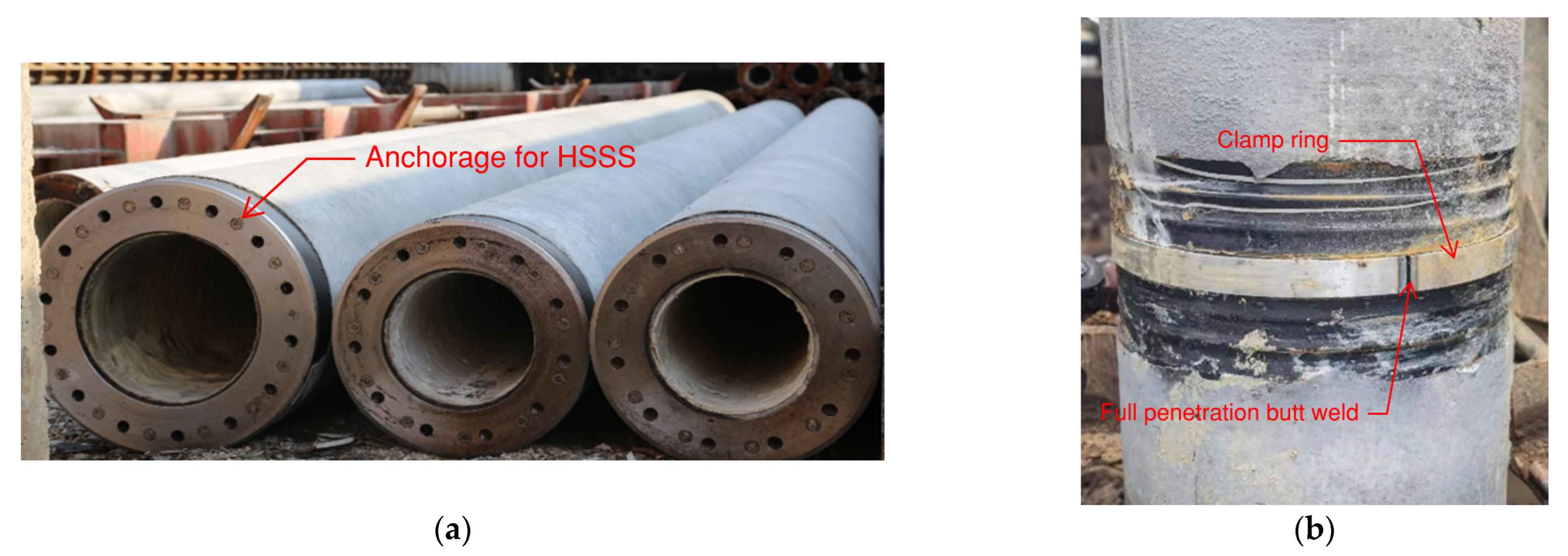
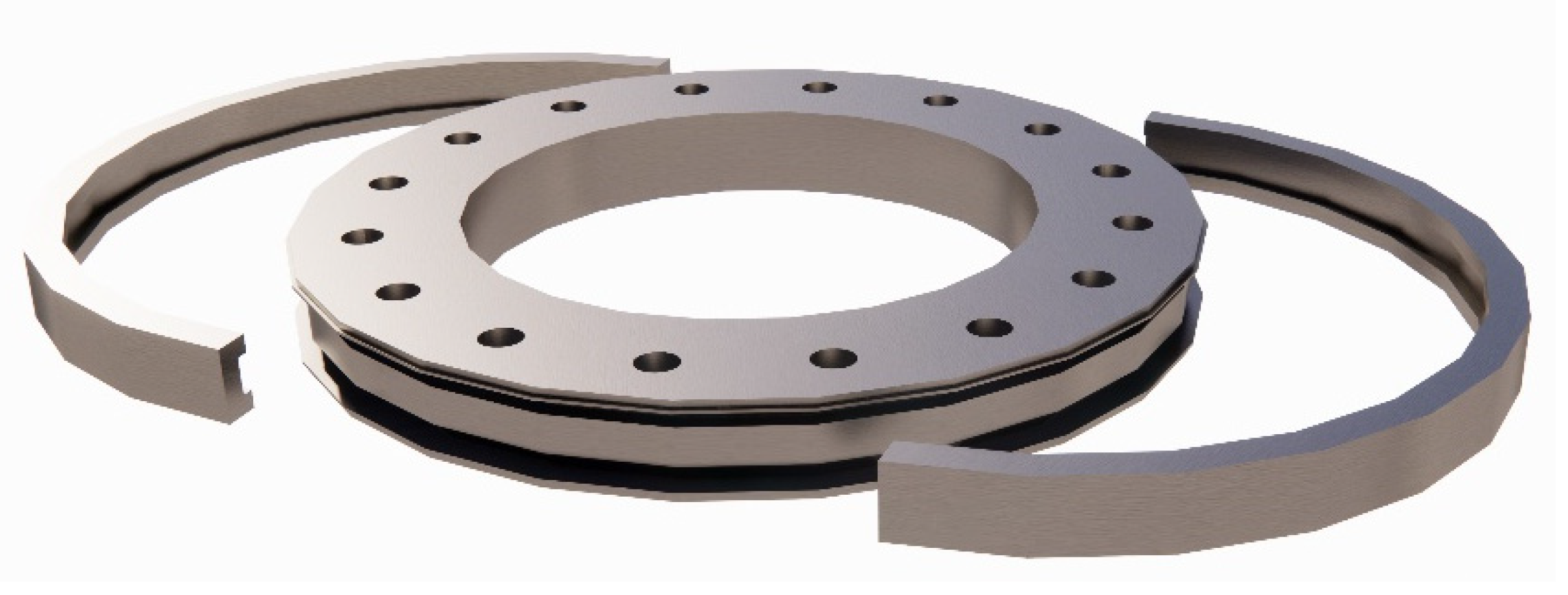
The Combination Splice is composed of two splice plates with grooves and two U-shaped semicircular clamp rings (see Figure 1). Splice plates also serve as the anchor plates for high-strength steel strands (see Figure 1a). The upper pile and lower pile splice plates are first vertically aligned during field installation, and then two semicircular clamps are inserted into the splice plates’ concave groove. Following clamp installation, a full-penetration butt weld between the two clamps is required to make them function as a clamp ring (see Figure 1b). Figure 2 shows a 3D rendering of the Combination Splice. This Combination Splice embodies the respective advantages of mechanical splices and welded splices. The merits of the Combination Splice are: (i) easy handling, transporting, and reducing time for installation; (ii) reliable and safe force transmission between piles; (iii) economic and able to be stored in the precast yard and construction site; (iv) flexible adjustability in unsatisfied situations such as centering deviation between two splice plates.
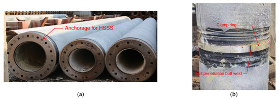
Figure 1.
Schematic graph of Combination Splice: (a) Splice plates; (b) Clamp ring.
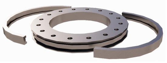
Figure 2.
Combination Splice.
When PPCP using HSSS supports vertical loads from superstructures, two splice plates of the upper and lower PPCP directly transmit pressure through close contact, and the clamp ring is essentially not compressed. The clamp ring begins to function and transmit force from one pile to another through the contact between the splice plate and clamp ring when tension develops in heaps as a result of a rise in the water level or for other reasons. A similar force transmission occurs when the piles and splices are supporting flexural or shear loads, but the contact surfaces are more complicated and alter as the load changes. In actual engineering, the tension load case is used to determine and design the precise dimensions of the Combination Splice.
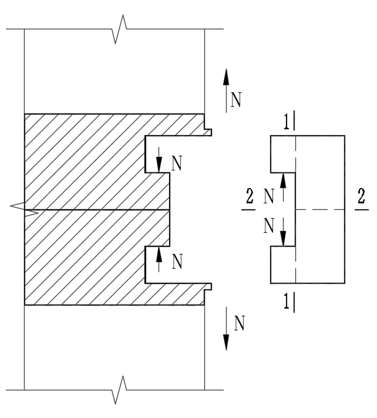
When the pile body is under tension, as shown in Figure 3, there are two important sections in the clamp ring: section 1-1 primarily bears the shear force and bending moment, while section 2-2 primarily bears the tensile force and bending moment. Through the design of these two crucial sections, the safety of the clamp and Combination Splice is also guaranteed.
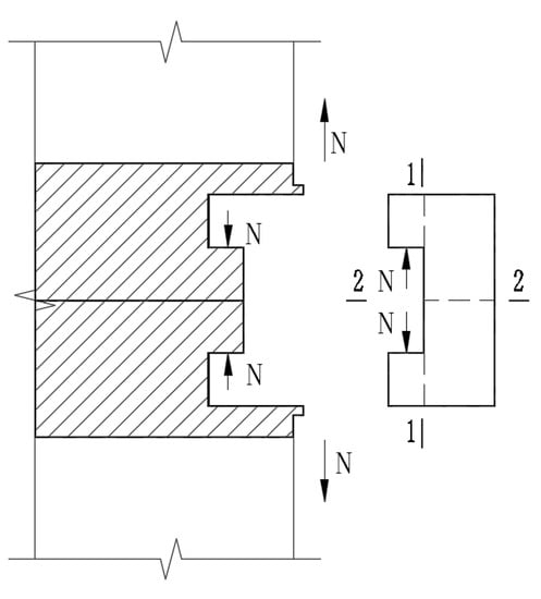
Figure 3.
Force analysis.
For section 1-1, the shear stress is:
where is the shear stress of section 1-1, is the axial tension, is the diameter of the groove of the U-shaped connecting clamp, represents the thickness of the U-shaped connecting clamp embedded in the end plate, and is the design value of the shear strength of the U-shaped connecting clamp material.
For section 1-1, the normal stress is:
where is the normal stress of section 1-1, is the bending moment of section 1-1, is the bending section modulus of section 1-1 of the U-shaped connecting clamp, represents the length of the U-shaped connecting clamp embedded in the end plate, is the inner diameter of the U-shaped connecting clamp, is the design value of the tensile strength of the U-shaped connecting clamp material.
For the normal stress of section 2-2:
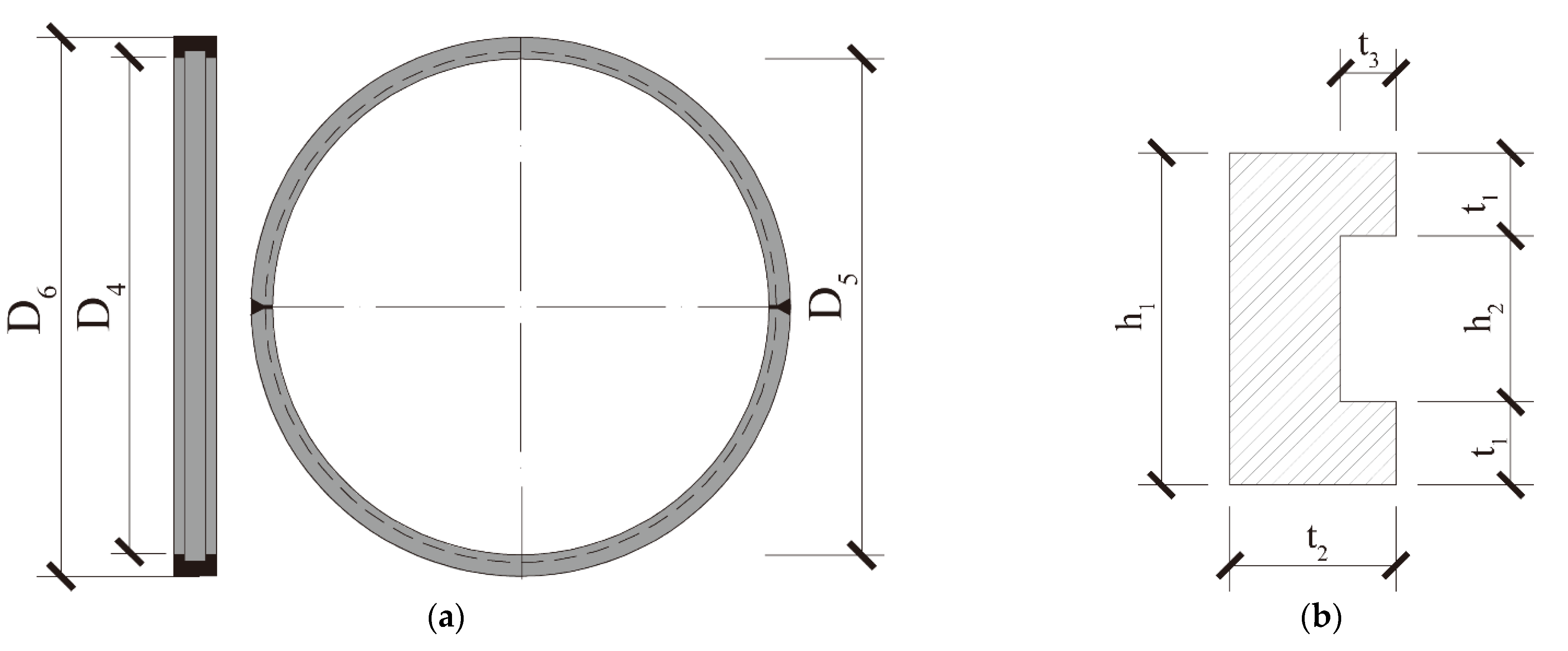
where is the normal stress of section 2-2, is the normal force caused by tension, is the normal force caused by the moment of section 2-2, is the thickness of the clamp, is the outer diameter of the clamp. Section 2-2 is under the tension and moment; the outer section of the clamp is of a different sign of normal stress, and the inner section is of the same sign of normal stress. The corresponding relationship between each parameter and clamp is shown in Figure 4 below.
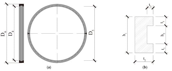
Figure 4.
Parameters of various parts of the clamp ring: (a) side and front view, (b) sectional drawing.
It is important to note that force analysis under tension is primarily used to estimate the detail size of the splice plate and clamp ring. Further study is required to determine whether this size can guarantee the Combination Splice’s bearing capability under a flexural moment.
3. Experimental Procedure
3.1. Specimen Materials and Properties
All specimens were constructed with seven-wire high-strength low-relaxation steel strands (HSSS) with nominal diameters of 11.1 mm and 15.2 mm. The control stress (σcon) used to prestress each steel strand was maintained at 75% of the nominal tensile strength of the HSSS, which had a nominal tensile strength of 1860 MPa. All pile specimens had spiral stirrups composed of grade-A cold-drawn low-carbon steel wires. It should be noted that due to the tensile testing machine’s difficulty in clamping small diameter stirrups such as Φb4 and Φb5 steel wires, the Φb6 steel wire from the same batch of wires was tested instead. The mechanical properties of the steel rebar are shown in Table 1. It is clear that the prestressing strands have a greater elongation than the Grade-A cold-drawn stirrup.

Table 1.
Mechanical properties of the steel.
The design strength grade of the concrete used for the pile test specimens was C105. Nine 100 mm concrete cubes were made prior to casting the piles and stored in the same curing environment as the pile specimens. The concrete cubes were tested immediately prior to the pile experiments. The average value for the cubic compressive strength fcu,10 of these test blocks was 116.1 MPa. The cubic compressive strength fcu, axial compressive strength fc, and tensile strength ft may then be determined as shown in Table 2 using the empirical formulas [19,20].
Table 2.
Mechanical properties of Concrete using Empirical formulas.
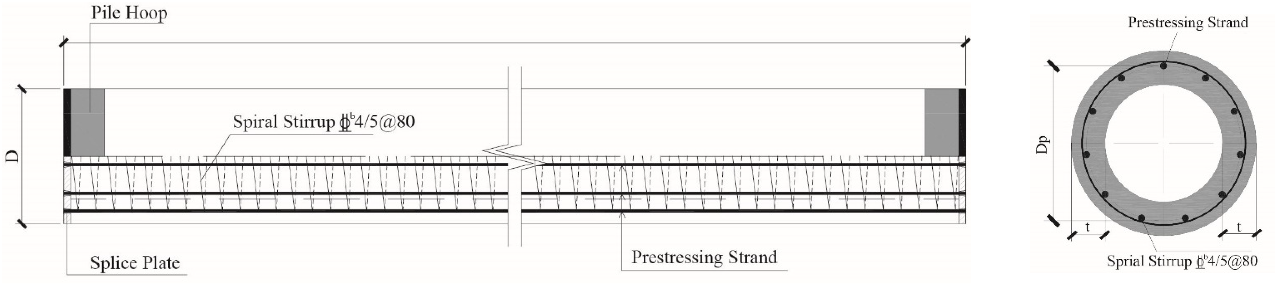
To suit various engineering demands, PPCPs utilized in real applications typically have external diameters of 400 mm, 500 mm, and 600 mm. In accordance with the dimensions of PPCPs using HSSS, six full-scale pile specimens with external diameters of 400 mm(P4A/P4B), 500 mm(P5A/P5B), and 600 mm(P6A/P6B) were fabricated for the experimental study. Furthermore, two specimens with diameters of 500 mm but different reinforcement and splice dimensions (P5C/P5D) were tested to validate the Combination Splice design method. Examples of a cross-section of the proposed pile are provided in Figure 5. In order to produce the proposed specimens, (1) two 4-m-long pile segments were molded from high-strength concrete using a centrifugal force. Then, (2) two semi clamp rings were installed into the groove of the splice plates. (3) Finally, full-penetration butt welding was used in situ. More detailed dimensions of the proposed piles and Combination Splices are provided in Table 3 and Table 4.
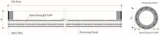
Figure 5.
Schematic diagram of reinforcements in pile test specimens: (unit: mm).
Table 3.
Detailed dimensions of specimen.
Table 4.
Detailed dimension of Combined Splice (units: mm).
3.2. Testing Instruments and Procedure
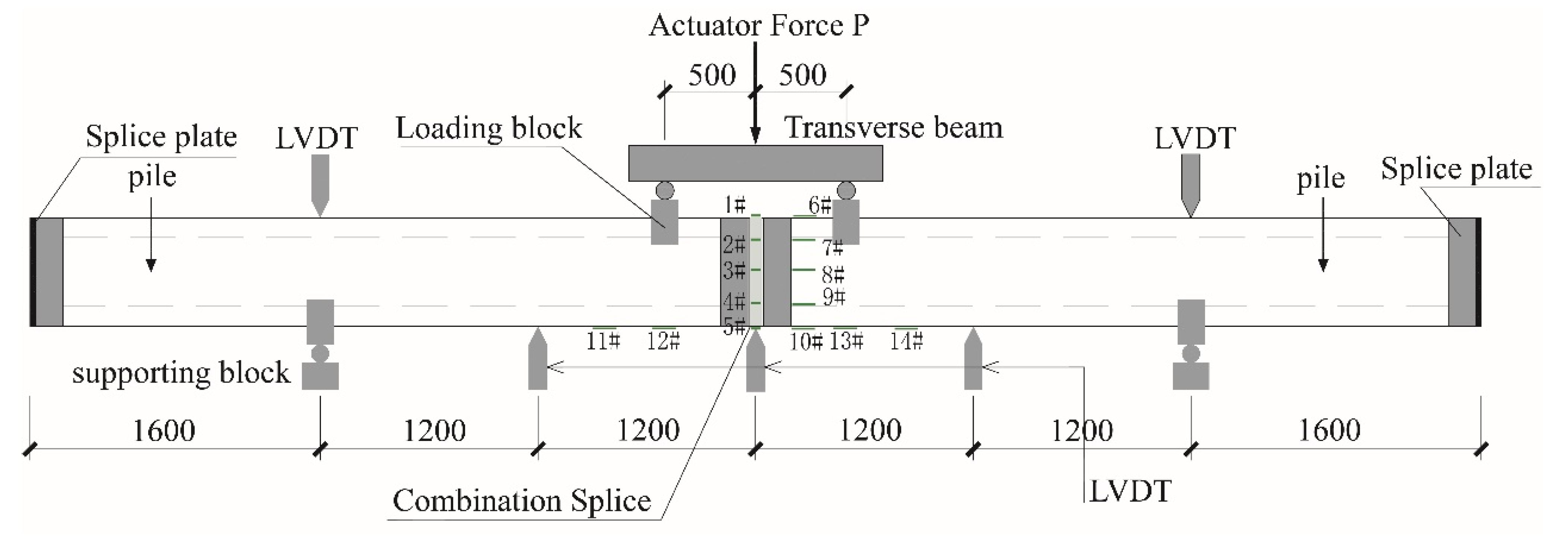
Each specimen was tested using a four-point bending setup under a monotonically increasing load until failure, as shown in Figure 6 and Figure 7. Five linear variable-differential transducers (LVDTs) were used to measure displacement. They were placed in the mid span (2400 mm away from supports) to measure specimen displacements, as well as the 1/4 span (1200 mm away from supports) and supports on both sides. All strain gauges were mounted on specimens outside surfaces since it was challenging to connect strain gauges to steel strands. Five electrical resistance strain gauges (1#~5#) were mounted on the clamp ring’s surface, and another nine electrical resistance strain gauges were installed on the pile’s surface. In detail, 6#~10# strain gauges were evenly distributed along the depth of the mid span section and on the concrete surface next to the Combination Splice. Strain gauges 11#~14# were equally placed along the bottom tensile edge near the mid span (±1200 mm). The piles’ cracking behaviors were observed visually.
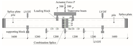
Figure 6.
Schematic diagram of the bending test setup and instruments.

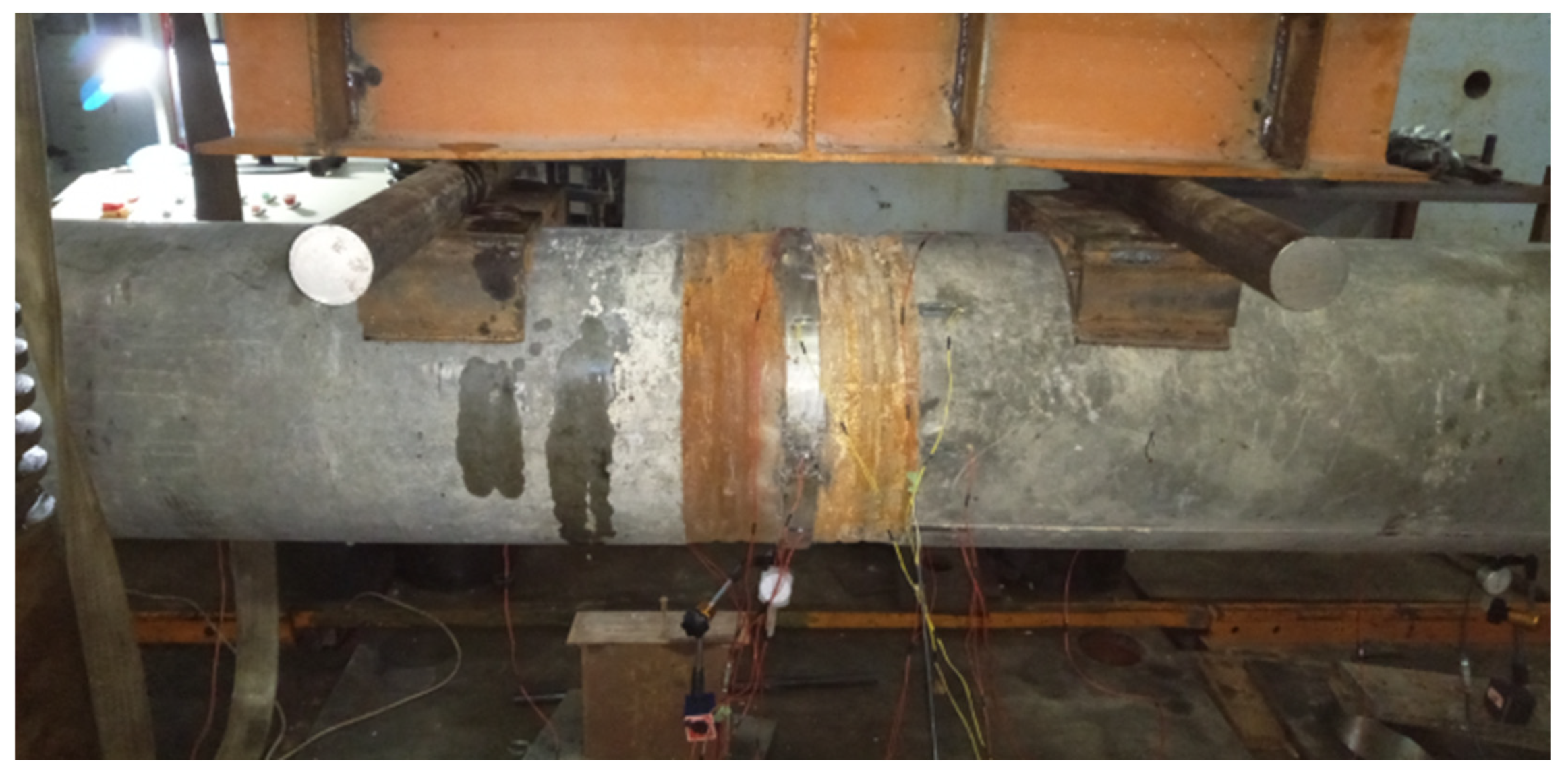
Figure 7.
Bending test setup and instruments photograph.
During the bending test, the computer-controlled hydraulic jack applies the vertical force P to the transverse beam, which is then uniformly transmitted to the loading blocks below. Both the loading and support blocks are constructed with Q345 steel, which keeps its elasticity throughout the test. The bending test loading strategy was then put into practice as follows: (i) loaded with a 10% increment of Mcr until the bending moment of the specimen reached 90% of Mcr in the mid span; (ii) a 5% increment of Mcr was subsequently applied until cracks appeared; (iii) loading was then continued at a rate of 5% Mu increments until the bending moment reached Mu in the mid span; (iv) loading was changed to a displacement-controlled mode with a 2 mm increment until the specimens were deemed to have failed. The following are the test termination criteria: (a) the concrete crack widens to 1.5 mm; (b) the tensile reinforcement breaks; (c) the concrete is crushed in the compression area; and (d) the Combination Splice is damaged or deformed.
4. Experimental Results and Analysis
4.1. General Observations
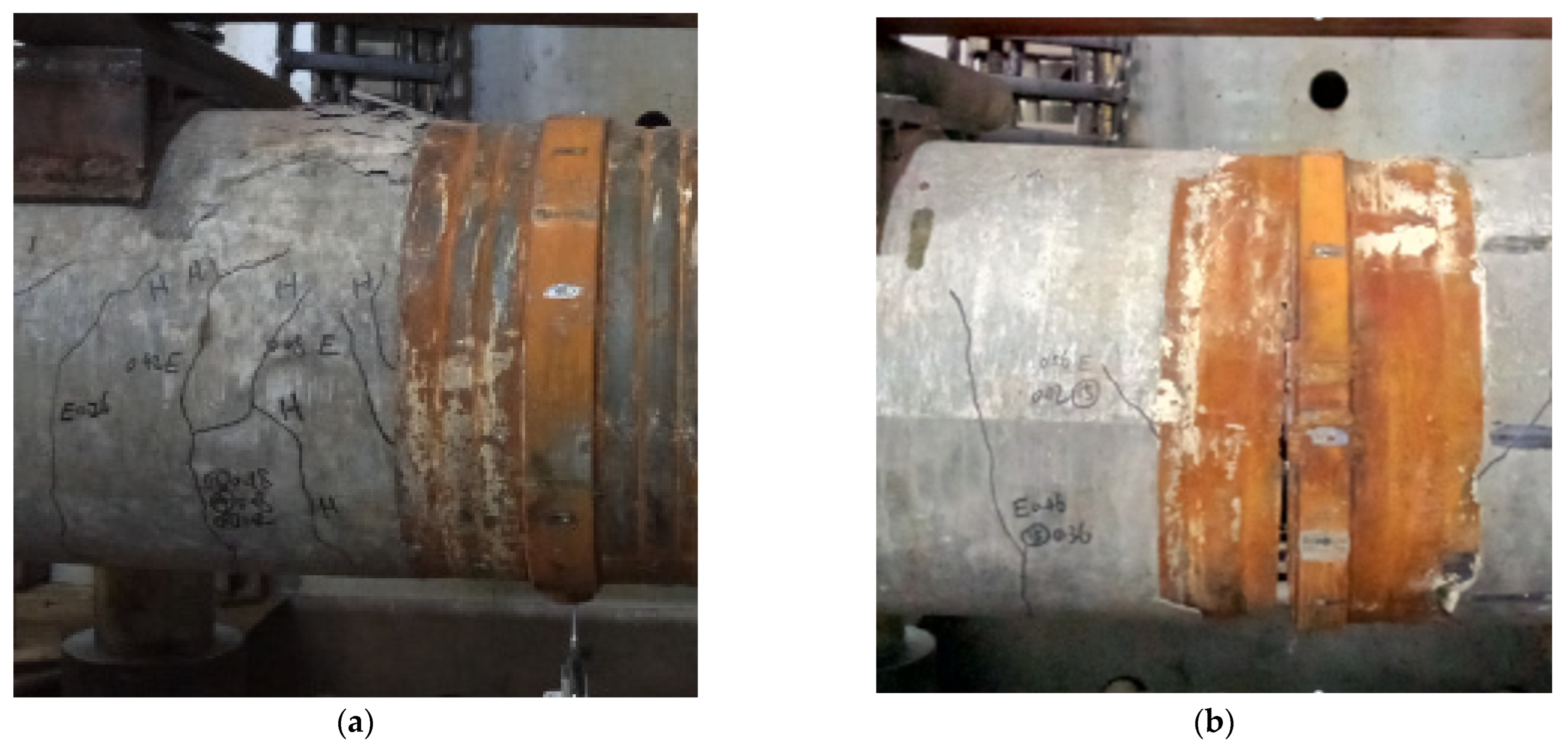
According to experimental phenomena, the most common failure model for PPCPs utilizing HSSS specimens is the crushing of the concrete in the compression area (Figure 8a), followed by the pulling off of the steel strands from the splice plates, while the Combination Splice is left intact. The steel strand pile specimen with the Combination Splice has equally and densely distributed cracks throughout the pile body, which successfully ensures the co-working capacity between two pile segments. There is no evident stress concentration or plastic deformation between the clamp ring and the splice plates, according to a thorough inspection of the Combination Splice. The Combination Splice is still in fine shape, demonstrating the reliability of this splice type’s “equal strength connection”. Another significant finding in specimen P4A, however, is that the anchorage failure (Figure 8b) happens just before the majority of the concrete in the compression zone collapses. To prevent early anchorage failure, more care should be taken, and measurements should be made.

Figure 8.
Failure modes of pile test specimens: (a) concrete crushing; (b) anchorage failure.
4.2. Load–Displacement Curves and Flexural Performance
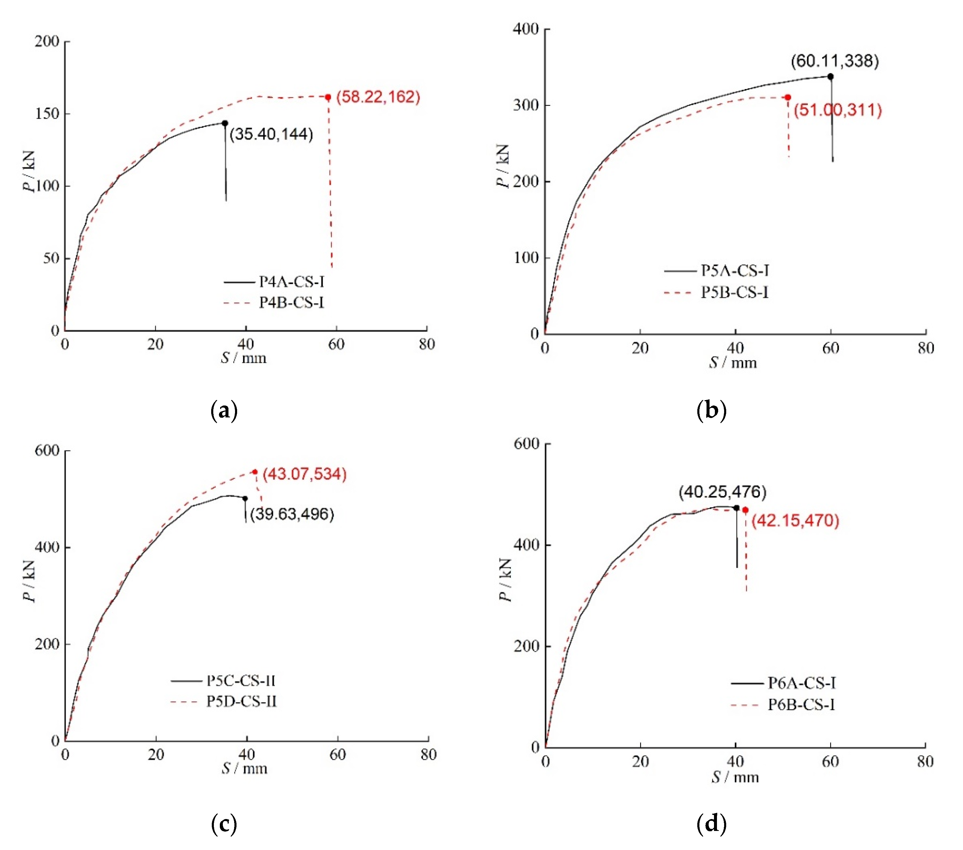
The mid-span load –displacement curves of eight PPCPs employing HSSS specimens are shown in Figure 9. Specific coordinate values are used to identify the ultimate load. Based on the load–displacement curves and the associated experimental data, the complete loading process may be generally separated into three different stages:
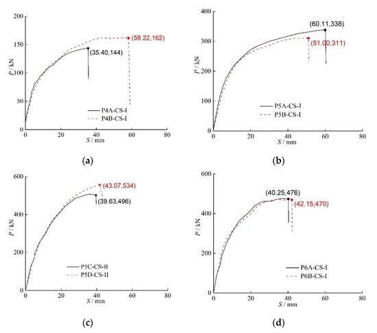
Figure 9.
Relationship between the load and the midspan displacement: (a) P4A-CS-I/P4B-CS-I, (b) P5A-CS-I/P5B-CS-I, (c) P5C-CS-II/P5D-CS-II, (d) P6A-CS-I/P6B-CS-I.
(1) Pre-cracking stage: From the start of loading to the emergence of the first crack, each specimen exhibited fairly linear elastic behavior, and the load increased linearly with mid-span displacement. (2) Nonlinear stage: When the first crack appeared in the mid-span area next to the Combination Splice, the pile specimens’ flexural rigidity dramatically dropped. The load–displacement curve has moved into a nonlinear phase. (3) The final stage, during which the concrete in the compression zone started to crumble as midspan displacement increased, the test specimens’ bearing capacity peaked, then started to decline, and the steel strands in the tension zone started to gradually pull out from the splice plates.
The stiffness and ultimate load-bearing capability of the two specimens with the same pile and splice dimensions are comparable. However, the P4A specimen exhibits a significant reduction in mid-span displacement as a result of the early anchorage failure. When comparing the identical Combination Splice type of the P4, P5, and P6 segments, the ultimate load increases, but mid span displacement reduces as the pile diameter and reinforcement increase. For the P5 specimens, the reinforcement ratio of the P5C/P5D pile is 1.87 times that of P5A/P5B, and the thickness of the steel plate of the Combination Splice (CS-II) is 1.42 times that of the steel plate of the P5A/P5B Combination Splice (CS-I). Comparing the load–displacement curves (Figure 9) and flexural performance parameters (Table 5) of P5C/P5D and P5A/P5B, it can be seen that the cracking load of P5C/P5D is increased by 46.1%, and the ultimate bending moment is increased by 57% relative to P5A/P5B. This implies that the configuration of more prestressing reinforcements helps to improve both the cracking and bending performance of the pile specimens. Comparing the ultimate displacements of the P5 specimens, it can be found that the ultimate displacements of P5C/P5D decreased by 26% compared with those of P5A/P5B, indicating that the increase in prestressing reinforcements will lead to a decrease in the ductility of the members.
Table 5.
Flexural performance parameters of specimens.
Key flexural performance metrics for several tested piles using the Combination Splice are compared in Table 5. Among them, is the cracking bending moment of the pile body using a theoretical formula and measuring concrete strength; is the ultimate bending moment of the pile body using theoretical formula and measuring concrete and steel strength; is cracking bending moment of the test specimen, is the ultimate bending moment of the test specimen, and fut is the test value of the maximum mid span displacement. As a result, the values of
and were quite similar, while the value of was 10% greater, on average, than that of . According to the results above, utilizing the Combination Splice to join piles has no detrimental effects on how well PPCPs bend.
4.3. Crack Distribution
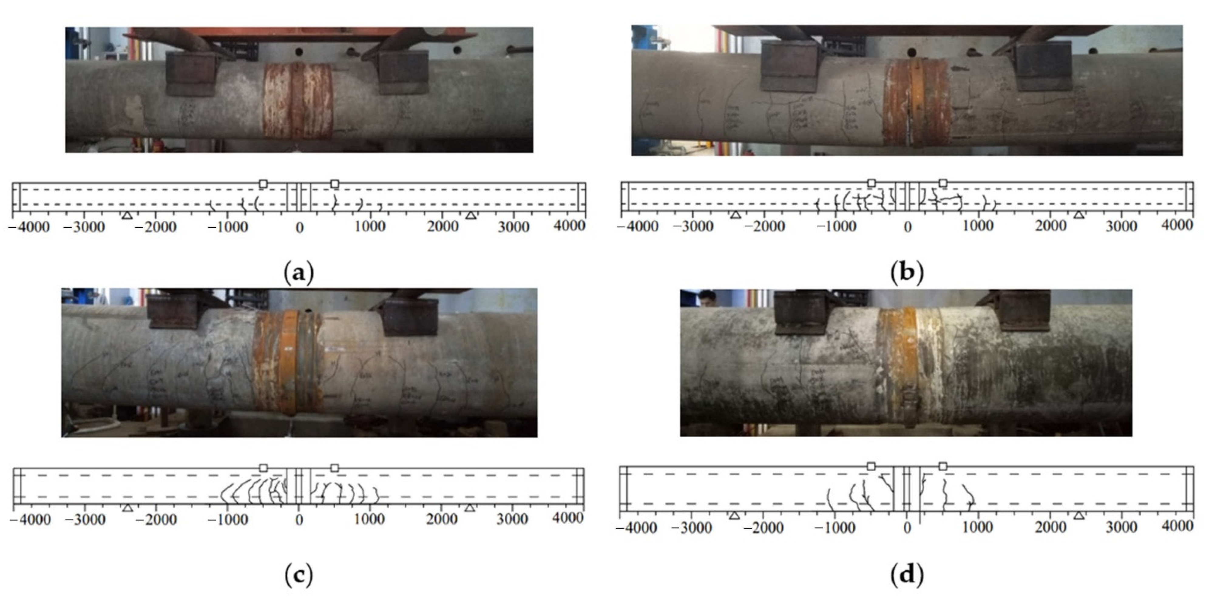
The tested piles’ crack distributions prior to total failure are shown in Figure 10. Since the crack patterns in the two specimens with the same diameter and reinforcement are comparable, only one result is shown below. All visually noticed cracks were meticulously measured throughout the experiment and are recorded in Table 6. The cracks in all other test specimens but P4A-CS-I were fully developed. Within a distance of −1000 mm to 1000 mm from the mid span region, the cracks were dispersed in the pure bending areas and the bending shear regions. The maximum crack width is between 0.68 mm and 1.22 mm, and the maximum crack length is 68–80% of the specimen’s section diameter.
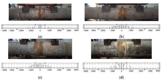
Figure 10.
Crack distribution of Specimens: (a) P4*-CS-I, (b) P5*-CS5-I, (c) P5*-CS5-III, (d) P6*-CS6-I.
Table 6.
Crack number and regions.
4.4. Strain Development
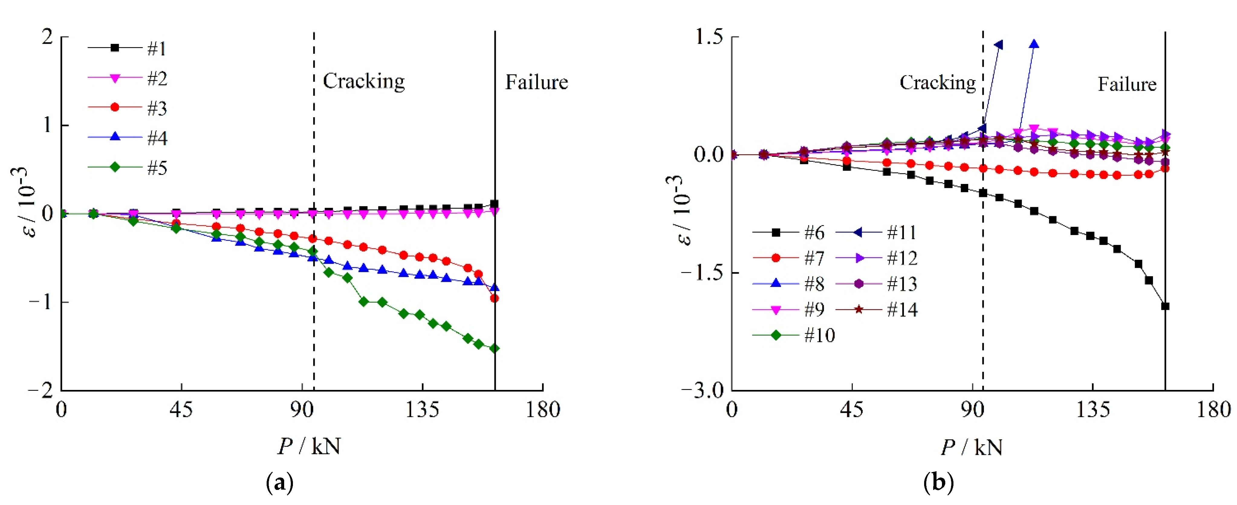
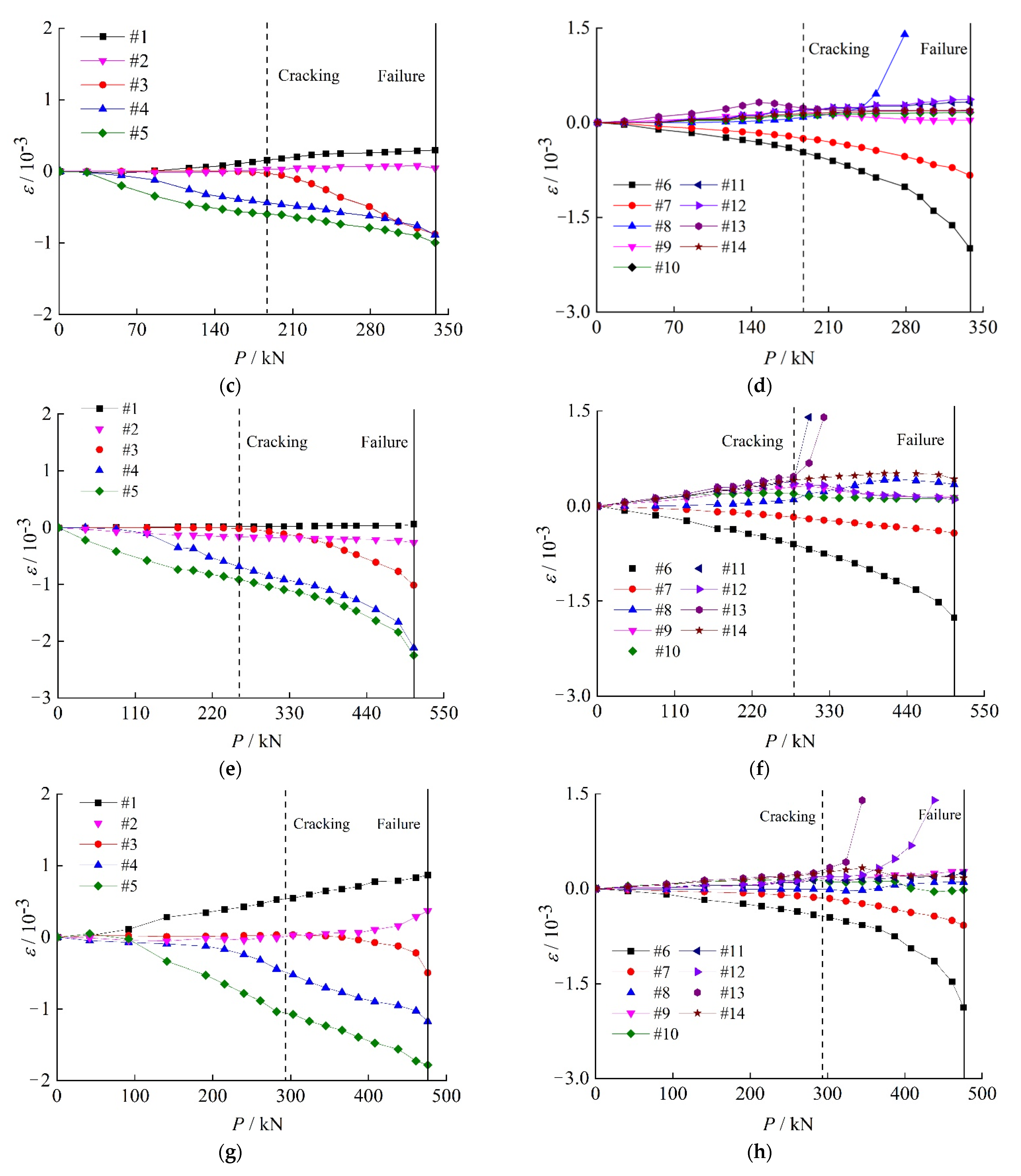
Figure 11 shows the relationship between the measured strains and the applied load. At specific locations, as shown in Figure 6, the strain gauges were set up to measure the clamp ring strain as well as the concrete strain of the pile test specimens. The primary purpose of the concrete strain gauges was to track the development of cracks as well as the strain distribution throughout the depth of the mid span section. Since the strain development of two specimens with the same diameter and reinforcement is identical, only one result for each specimen type was provided below.
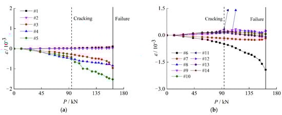
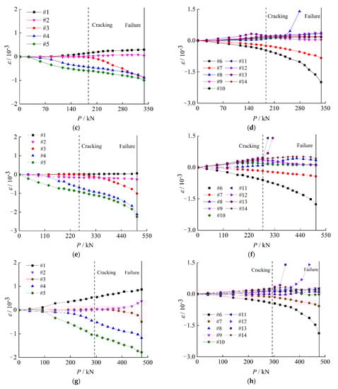
Figure 11.
Strain development of specimens: (a) Clamp strain of P4B-CS-I, (b) Concrete strain of P4B-CS-I, (c) Clamp strain of P5A-CS-I, (d) Concrete strain of P5A-CS-I, (e) Clamp strain of P5C-CS-I, (f) Concrete strain of P5C-CS-I, (g) Clamp strain of P6A-CS-I, (h) Concrete strain of P6A-CS-I.
On the graphs, two vertical straight lines were drawn: the continuous line represents the peak load at which specimens fail, and the dashed line represents the observed visible cracking load. The clamp strain and concrete strain have a linear relationship with increasing loads before cracks appear. Some concrete strain gauges show a significant increase in value when the load reaches the cracking load, indicating that the cracks have destroyed the gauges at that location. The concrete strain in the compression zone manifests a clear nonlinear development before reaching the failure load. Accordingly, when the member reaches the ultimate load, the clamp strain alters linearly. One interesting difference is that the outside surface of the clamp ring experiences compressive strain in the specimen’s tension zone, but the outer surface of the clamp ring experiences minor tension strain or nearly no strain in the specimen’s compression region. The theoretical analysis states that the clamp is regulated by bending compressive stress on the outer surface and is under the joint action of a bending moment and tension when it is in tension. However, because of the impact of the assembly gap and the Combination Splice’s machining accuracy, the contact position of the clamp and splice plates becomes more complicated. In general, the clamp ring does not directly participate in the transmission of compression force due to close contact between two splice plates and the assembly gap between the clamp and splice plate; therefore, the surface strain of the clamp should be essentially zero. The clamp ring may assist in bearing the pressure and be subject to the combined action of the bending moment and pressure when the assembly gap is small, the splice plate cannot be in close contact, or local deformation in splice plates occurs. The clamp surface is governed by bending tensile stress because the load direction for compression is directly opposite that for tension. The analysis mentioned above demonstrates how intricately complicated the contact state and stress distribution of the Combination Splice are.
5. Finite Element Analysis
A thorough nonlinear finite element analysis (FEA) was conducted using the program ABAQUS to forecast the response of the Combination Splice of PPCP employing HSSS under a flexural load. The FEA model is validated using the experimental findings. More extensive parametric investigations can be carried out using a verified FEA model to examine the damage evolution of specimen piles and the Combination Splice.
5.1. Constitutive Law of Material
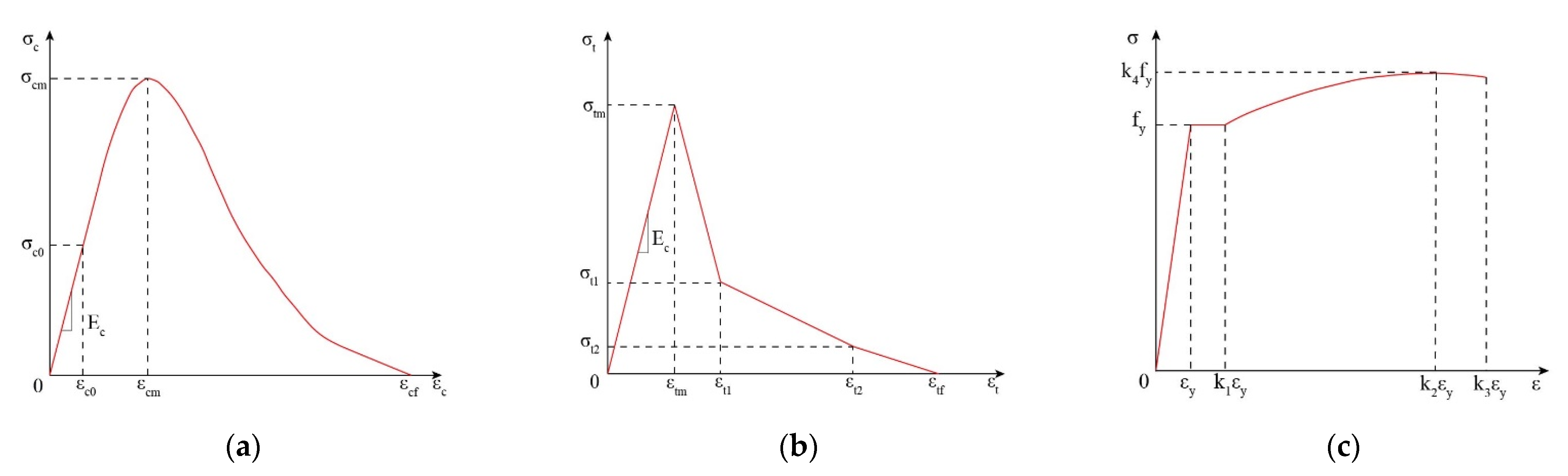
In the FEA model of the piles, the concrete-damaged plasticity (CDP) model from ABAQUS is utilized to represent the high-strength concrete. By combining isotropic elastic damage with isotropic tensile and compressive plasticity, the CDP model defines the inelastic behavior of concrete. There are many constitutive laws for concrete material in the literature [19,20], and the model proposed in this study for high-strength concrete [9,21,22] is shown in Figure 12a,b.
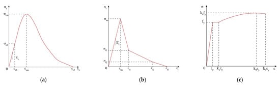
Figure 12.
Constitutive law of material: (a) uniaxial compression of concrete, (b) uniaxial tension, (c) uniaxial tension for rebar.
The constitutive law for concrete under uniaxial compression is expressed as:
The constitutive law for concrete under uniaxial tension is expressed as:
The constitutive law for stirrup and HSSS is expressed as:
In Table 7, the specific values to determine the constitutive law of concrete and steel rebars are given. For concrete materials with a strength over C80, the definition of tensile and compressive damage curves in the CDP model lacks sufficient theoretical and experimental data. Additionally, the parameter sensitivity analysis of the numerical model demonstrates that it is possible to ignore the impact of whether or not the damage curve should be defined on the load–displacement curve and in the final bearing capacity of monotonic bending tests. The damage curve is not, therefore, included in the finite element model.
Table 7.
Key parameters to determine the constitutive law of materials.
5.2. Interaction and Constraints
When the pile specimen with the Combination Splice deforms under a bending moment, compression, separation, and friction will occur in different parts of the specimen. To accurately simulate these detailed states, it is necessary and desirable to define the interaction and constraints for each part in the finite element model. The detailed interaction and constraints are shown in Table 8.
Table 8.
Interaction and Constraints.
5.3. Finite Element Analysis Model
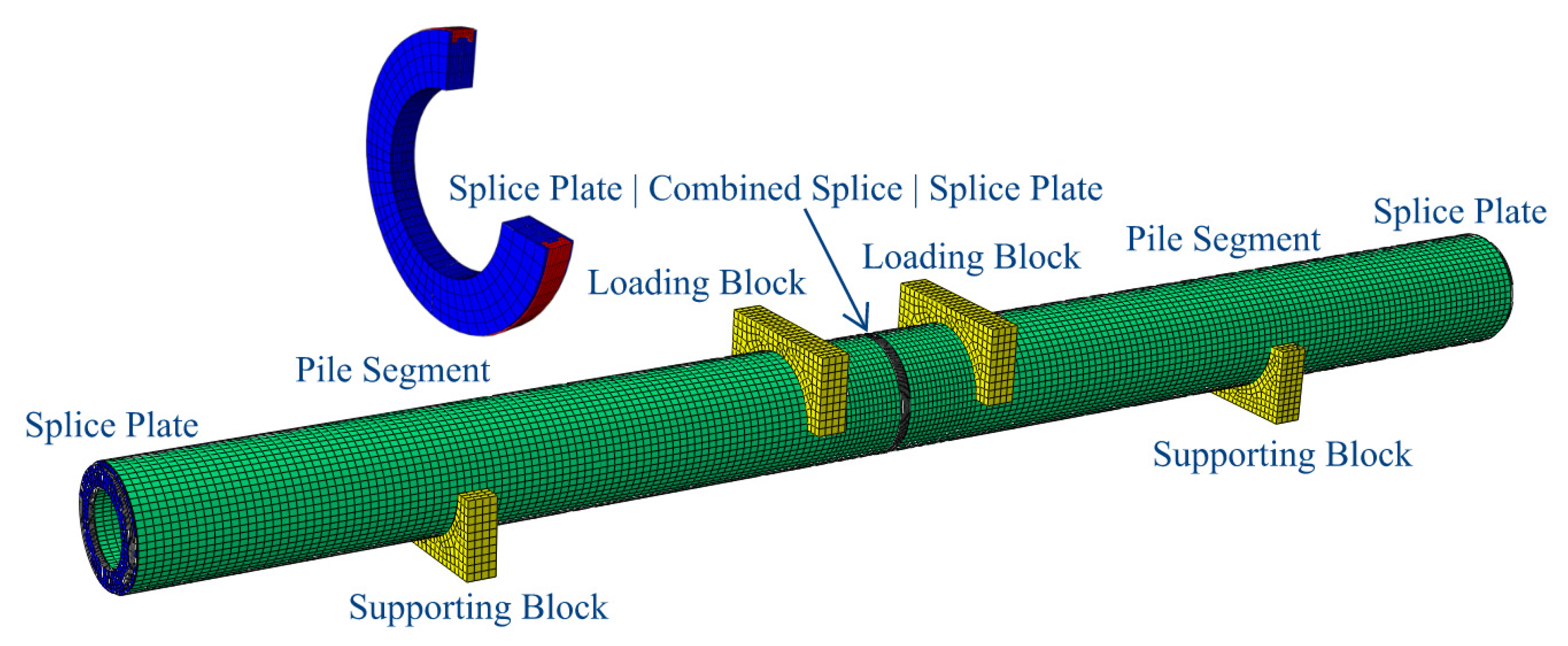
Figure 13 depicts the finite element model’s schematic diagram. The exact dimensions of the piles, splice plates, and clamp rings in the FEA remain consistent with the geometry of the actual specimen. To make the model more straightforward, the clamp ring is modeled as a complete connecting ring, and the steel annular plate and welding seam in the Combination Splice are ignored. Two elastic loading blocks and two elastic supporting blocks are constructed to prevent abnormal stress concentration at the loading and supporting locations.
Figure 13.
Schematic diagram of the finite element model.
The solid elements are represented by an eight-node three-dimensional solid element with reduced integration (C3D8R), and the reinforcing rebars are represented by a two-node three-dimensional truss element (T3D2). Table 9 shows the element type for a variety of FEA model components.
Table 9.
Element type of FEA model.
5.4. Numerical Results Validation
5.4.1. Load–Displacement Curves
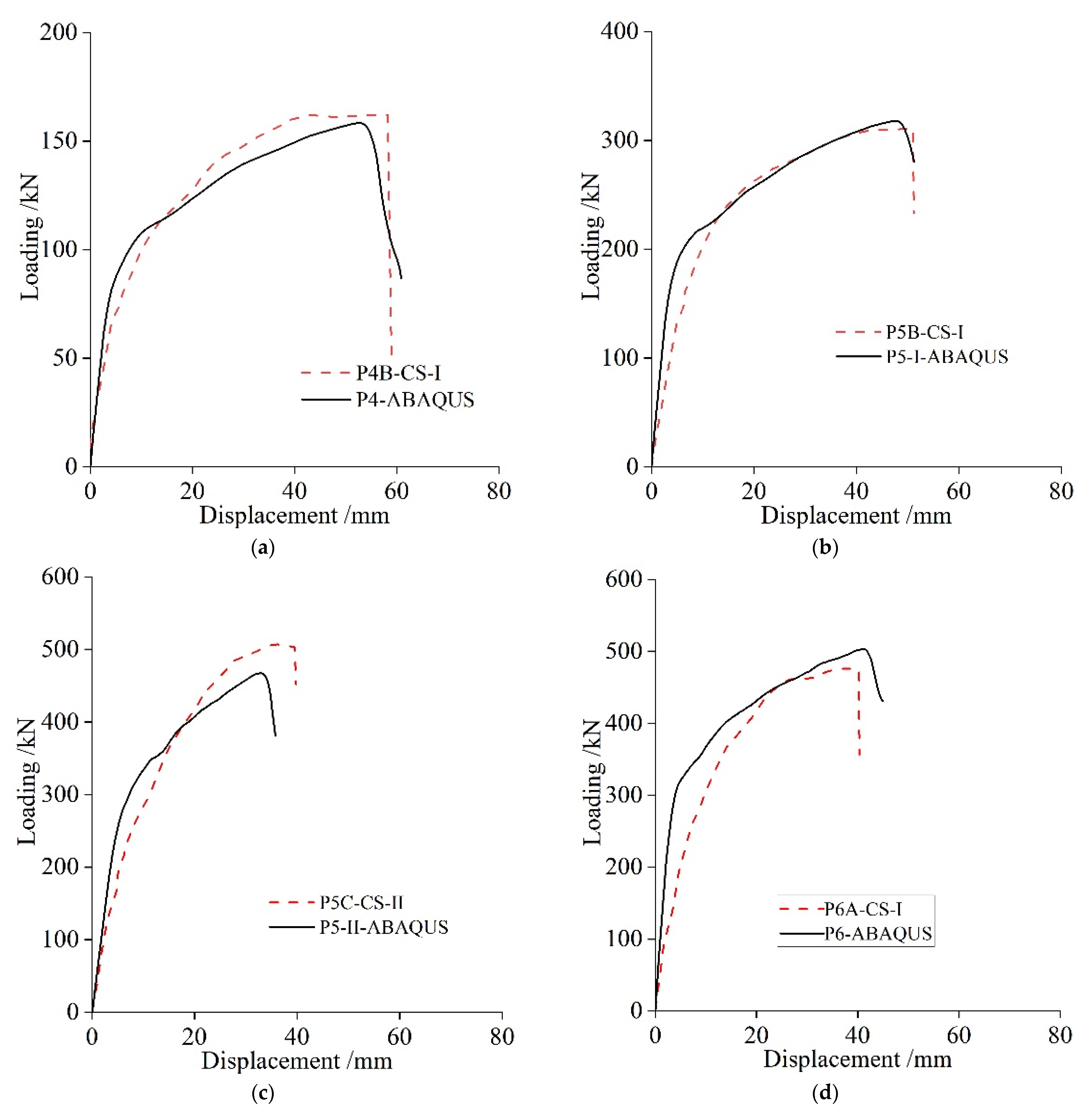
The bending response of the test piles with the Combination Splice is examined using the material characteristics, interaction settings, and finite element model. The comparison of four distinct pile types’ experimental data and results from numerical simulations on the load–displacement curve is shown in Figure 14. As can be seen, the ultimate load and displacement derived from the simulation are consistent with the experimental values, and the development trend of the simulation curve is essentially consistent with the experimental curve. The numerical simulation curve’s slope, however, is greater than the experimental curve at the time before cracking. One reason could be that there are some gaps in the specimens’ real assembly when using the Combination Splice. With an increase in force, the gaps began to close during the experiment, reducing the stiffness of the test specimens. The bending stiffness of the simulated curve rapidly drops from the point of specimen failure through cracking, which is in good agreement with the test curve.
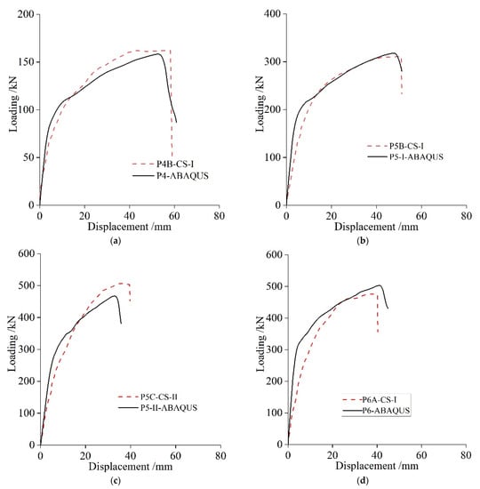
Figure 14.
Comparison of load–displacement curves between FEA and experimental results: (a) P4B-CS-I, (b) P5B-CS-I, (c) P5C-CS-II, (d) P6A-CS-I.
5.4.2. Crack Distribution
Cracks are expected to form when the maximum principle plastic strain of concrete is positive in the CDP concrete material model, and the direction of the cracks may be observed using the maximum principal plastic strain [9]. In this numerical simulation, the development of cracks in piles is described by the maximum principal plastic strain of concrete rather than tensile damage. When the ultimate bending capacity is attained, Figure 15 illustrates a comparison of the fracture distribution between computational and experimental data. It can be shown that the crack development generated from the numerical model, including the distribution and evolution of the fracture area, is compatible with the experimental data.

Figure 15.
Crack distribution of numerical and experimental results for specimens: (a) P4-CS-I, (b) P5-CS-I, (c) P5-CS-II, (d) P6-CS-I.
6. Parametric Analysis
The flexural performance of PPCPs employing HSSS with the Combination Splice is investigated using parametric analysis based on the confirmed FEA model. The influences of two parameters are studied, including the assembly gap of the Combination Splice and the uniform corrosion of the clamp ring.
6.1. Assembly Gap of the Combination Splice
As mentioned in Section 4.4, the contact state and stress distribution of the Combination Splice are rather complex. In fact, the contact state between the clamp ring and the end plate is exceptionally complicated by the machining accuracy and the roughness of the contact surface. Moreover, the local separation, local contact, or contact surface expansion occur with the load change, making it impractical to study the detailed stress state. In engineering practice, the zero gap between different parts of the Combination Splice is almost impossible. To study the effect of the assembly gap, three different gap distances are simulated using a verified FEA model. The gap distance is shown in Figure 16, and the load–displacement curves of three gaps of Combination Splices are plotted in Figure 17. It can be seen that the distance of the assembly gap has a large impact on the load carrying capacity and ductility of the members using the Combination Splice. Unlike the zero-gap model, in the models with larger gaps (0.2 mm and 0.5 mm), some of the contact surfaces may not be involved in the forces all the time, even when the loads reach their ultimate values. This change in the force transfer path leads to a decrease in the bearing capacity and ductility. For models with smaller gaps (0.1 mm), the previously open contact surfaces may reclose and participate in the force whenever the load changes and the member deforms, eliminating, to some extent, the negative effects of the gap. More subsequent studies need to be conducted to determine a reasonable assembly clearance value for engineering practice.
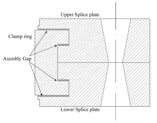
Figure 16.
Assembly gap of Combination Splice.
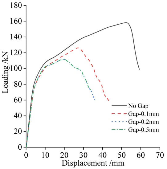
Figure 17.
Load –Displacement curves of different gap distances.
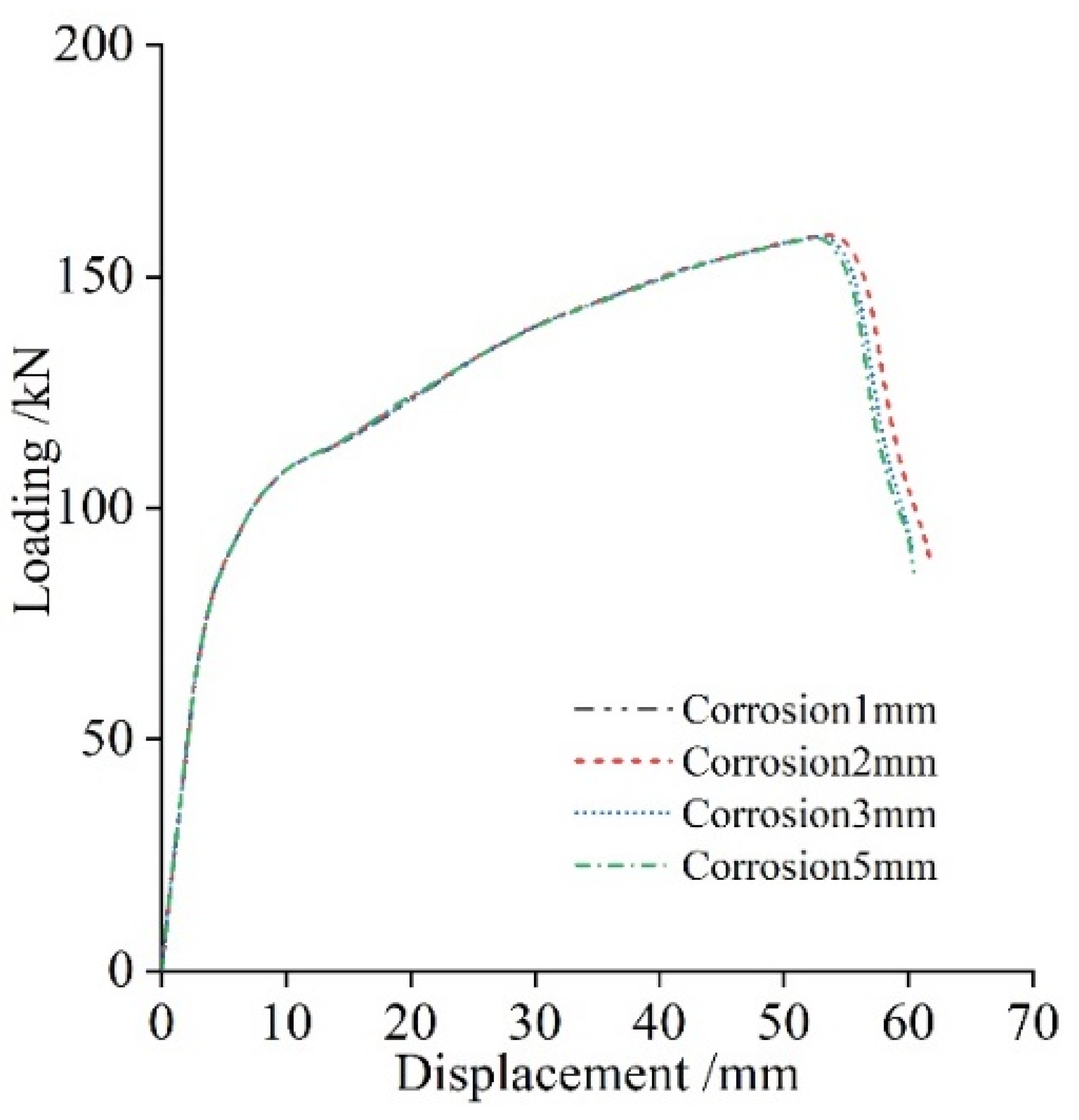
6.2. Uniform Corrosion of the Clamp Ring
For mechanical and welded splices, one of the problems with using those splices is their corrosion potential, especially in corrosive soils and marine environments [2,18]. Since the main potential corrosion location of the Combination Splice is at the outer surface of the clamp ring, four different corrosion thicknesses were designed on the clamp ring to investigate the effect of corrosion on the flexural performance of the piles using a validated finite element model. The uniform corrosion thickness of the clamp ring is shown in Figure 18, and the load–displacement curves of different corrosion thicknesses are plotted in Figure 19. It can be seen that corrosion has little effect on the flexural resistance of the members with the Combination Splice. Even when the corrosion thickness reaches 5 mm, the pile members with the Combination Splice still maintain almost the same load capacity and ductility as the initial design. This indicates that the size determined by the design method in this paper is conservative and reasonable. As the corrosion thickness increases and the effective cross-section decreases, the stresses on the clamp rings increase, and these data are not presented in this paper.
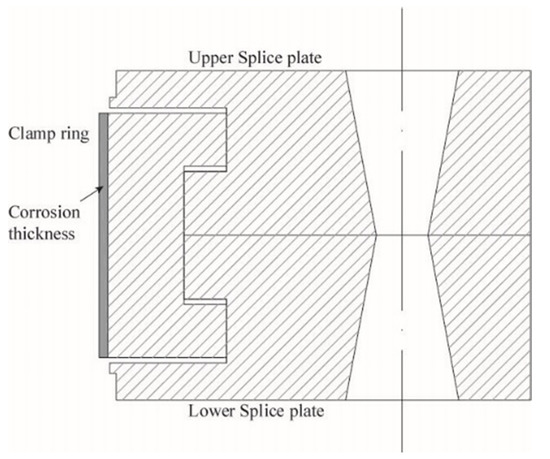
Figure 18.
Uniform corrosion of clamp rings.
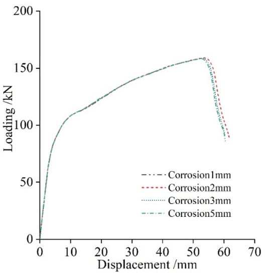
Figure 19.
Load–displacement curves of different corrosion thicknesses.
7. Conclusions
To study the bearing capacity of PPCPs using HSSS with the Combination Splice, four pairs of full-scale pile specimens (eight specimens in total) with different diameters, reinforcement ratios, and Combination Splice dimensions have been investigated experimentally and numerically. The main conclusions can be summarized as follows:
1. The majority of the PPCP failure models utilizing HSSS specimens involve crushing the concrete in the compression area before the steel strands are pulled free from the splice plates. This failure mode is ductile and favorable. When designing the anchorage plates of PPCPs using HSSS, sufficient measures shall be taken to limit the slip between steel strands and splice plates. The Combination Splice endures the entire testing process unharmed.
2. The cracking moments of test specimens with splices are remarkably similar to those of the theoretical calculation using the measured material strength. Moreover, using a theoretical formula and measured strength, the ultimate bending moment was, on average, 10% larger than that of the theoretical calculation.
3. The cracks of test piles using the Combination Splice were densely and evenly distributed in the pure-bending regions and shear-bending regions within the range of −1000 mm to 1000 mm from the mid span. The maximum crack length reached 68–80% of the specimen diameter, and the maximum crack width was between 0.68 mm and 1.22 mm.
4. Before reaching the ultimate load, the concrete strain in the compression zone shows obvious nonlinear development. Correspondingly, the clamp strain changes linearly when the specimen reaches the ultimate load. The strain result shows that the theoretical analysis and design method are effective in determining the size of the Combination Splice.
5. The load–displacement curves and crack development of the FEA model accord well with the experimental data, which demonstrates the credibility and accuracy of the FEA model in simulating the flexural performance of PPCPs using HSSS splicing with the Combination Splice.
6. According to parametric analyses, the flexural capacity is greatly impacted by the assembly gap of the Combination Splice; however, the corrosion thickness of the clamp ring has little influence on the flexural strength of the PPCP employing HSSS. More subsequent studies need to be conducted to determine a reasonable assembly gap value for engineering practice.
Author Contributions
Conceptualization, G.G.; methodology, G.G.; software, K.C.; validation, K.C; formal analysis, G.G. and K.C.; investigation, K.C.; resources, G.G.; data curation, K.C.; writing—original draft preparation, K.C.; writing—review and editing, G.G.; visualization, K.C.; supervision, G.G.; project administration, G.G.; funding acquisition, G.G. All authors have read and agreed to the published version of the manuscript.
Funding
This research was funded by the Center for Balance Architecture of Zhejiang University (Grant number: K-20203330C), Ministry of Housing and Urban-Rural Development of China, (Grant number: 2021-K-030) and Department of Construction of Zhejiang Province, China (Grant number: 2021K157).
Institutional Review Board Statement
Not applicable.
Informed Consent Statement
Not applicable.
Data Availability Statement
Not applicable.
Conflicts of Interest
The authors declare no conflict of interest.
References
- Yang, Z.; Li, G.; Wang, W. Experimental Investigation and Nonlinear Finite Element Analysis on Seismic Performance of PHC Piles. Struct. Eng. Int. 2018, 28, 475–488. [Google Scholar] [CrossRef]
- Khedmatgozar Dolati, S.S.; Mehrabi, A. Review of Available Systems and Materials for Splicing Prestressed-Precast Concrete Piles. Structures 2021, 30, 850–865. [Google Scholar] [CrossRef]
- Nagae, T.; Hayashi, S. Earthquake-Resistant Property of Prefabricated High-Strength Concrete Pile. In Proceedings of the High Performance Materials in Bridges; American Society of Civil Engineers: Kona, HI, USA, 5 September, 2003; pp. 173–182. [Google Scholar]
- Tokimatsu, K.; Tamura, S.; Suzuki, H.; Katsumata, K. Building Damage Associated with Geotechnical Problems in the 2011 Tohoku Pacific Earthquake. Soils Found. 2012, 52, 956–974. [Google Scholar] [CrossRef]
- Wang, W.D.; Li, Q.; Hu, Y.; Shi, J.W.; Ng, C.W.W. Field Investigation of Collapse of a 13-Story High-Rise Residential Building in Shanghai. J. Perform. Constr. Facil. 2017, 31, 04017012. [Google Scholar] [CrossRef]
- Wang, T.C.; Yang, Z.J.; Zhao, H.L.; Wang, W.J. Seismic Performance of Prestressed High Strength Concrete Piles. Mater. Res. Innov. 2014, 18, S2-515–S2-521. [Google Scholar] [CrossRef]
- Irawan, C.; Suprobo, P.; Putu Raka, I.G.; Djamaluddin, R. A Review of Prestressed Concrete Pile with Circular Hollow Section (Spun Pile). J. Teknologi 2015, 72, 115–123. [Google Scholar] [CrossRef]
- Thusoo, S.; Kono, S.; Hamada, J.; Asai, Y. Performance of Precast Hollow Steel-Encased High-Strength Concrete Piles. Eng. Struct. 2020, 204, 109995. [Google Scholar] [CrossRef]
- Ren, J.; Xu, Q.; Chen, G.; Liu, C.; Gong, S.; Lu, Y. Flexural Performance of Pretensioned Centrifugal Spun Concrete Piles with Combined Steel Strands and Reinforcing Bars. Structures 2021, 34, 4467–4485. [Google Scholar] [CrossRef]
- Yang, Z.-J.; Wang, W.-J.; Kang, G.-Y. Analysis on the Ductility of Prestressed High Strength Concrete Pile under Cyclic Loading. Eng. Mech. 2016, 33, 107–112. [Google Scholar] [CrossRef]
- Gan, G.; Zeng, K.; Yu, X.; Gong, S.; Xie, J. Construction and experimental verification of pretensioned centrifugal concrete pile provided with steel strands. China Concr. Cem. Prod. 2019, 3, 35–39. [Google Scholar] [CrossRef]
- Ikeda, S. Ductility Improvement of Prestressed Concrete Piles. Trans. Jpn. Concr. Inst. 1982, 4, 531–538. [Google Scholar]
- Muguruma, H. Improving the Flexural Ductility of Pretensioned High Strength Spun Concrete Piles by Lateral Confining of Concrete. In Proceedings of the Pacific Conference on Earthquake Engineering, Wairakei, New Zealand, 5–8 August 1987; Volume 1, pp. 385–396. [Google Scholar]
- Gan, G.; Zeng, K.; Yu, X.; Gong, S.; Chen, G.; Xu, Q. Experimental study on tensile performance of pretensioned prestressed centrifugal concrete steel stranded pile and its mechanical connection joints. Build. Struct. 2021, 51, 115–120+114. [Google Scholar] [CrossRef]
- Liu, Y. Study on Flexural Performance of Pretensioned Centrifugal Spun Concrete Piles with Steel Strands. Master’s Thesis, Zhejiang University, Hangzhou, China, 2021. [Google Scholar]
- Zhou, Q. Investigation on Mechanical Properties of Prestressed Steel Strand Ultra-High Strength Concrete Pipe Piles. Master’s Thesis, Zhejiang University, Hangzhou, China, 2018. [Google Scholar]
- Bruce, R.N.; Hebert, D.C. Splicing of precast prestressed concrete piles: Part i-review and performance of splices. PCI J. 1974, 19, 70–97. [Google Scholar] [CrossRef]
- Wei, D.; Wang, P. Investigation on Corrosion of Welded Joint of Prestressed High-Strength Concrete Pipe Piles. Procedia Eng. 2017, 210, 79–86. [Google Scholar] [CrossRef]
- Ke, X. Study on Seismic Performance and Design Method of New High-strength Concrete Composite Columns. Ph.D. Thesis, Xi’an University of Architecture and Technology, Xi’an, China, 2014. [Google Scholar]
- Wee, T.H.; Chin, M.S.; Mansur, M.A. Stress-Strain Relationship of High-Strength Concrete in Compression. J. Mater. Civ. Eng. 1996, 8, 70–76. [Google Scholar] [CrossRef]
- Velasco, R.V. Self-Consolidating Concretes Reinforced with High Volumetrics Fractions of Steel Fibers: Rheological, Physics, Mechanics and Thermal Properties. Ph.D. Thesis, Federal University of Rio de Janeiro, Rio de Janeiro, Brazil, 2008. [Google Scholar]
- An, C.; Castello, X.; Duan, M.; Toledo Filho, R.D.; Estefen, S.F. Ultimate Strength Behaviour of Sandwich Pipes Filled with Steel Fiber Reinforced Concrete. Ocean. Eng. 2012, 55, 125–135. [Google Scholar] [CrossRef]
Publisher’s Note: MDPI stays neutral with regard to jurisdictional claims in published maps and institutional affiliations. |
© 2022 by the authors. Licensee MDPI, Basel, Switzerland. This article is an open access article distributed under the terms and conditions of the Creative Commons Attribution (CC BY) license (https://creativecommons.org/licenses/by/4.0/).