Article

Influence of Defoamer on the Properties and Pore Structure of Cementitious Grout for Rebar Sleeve Splicing

1
College of Architecture and Design, University of South China, Hengyang 421001, China
2
School of Civil Engineering, Hunan University of Technology, Zhuzhou 412007, China
3
Hengyang Key Laboratory of Ecological Regions-Urban Planning and Management, Hengyang 421001, China
4
Hunan Province Healthy City Construction Engineering Technology Research Center, Hengyang 421001, China
*
Author to whom correspondence should be addressed.
Buildings 2023, 13(1), 170; https://doi.org/10.3390/buildings13010170
Submission received: 3 December 2022 / Revised: 27 December 2022 / Accepted: 4 January 2023 / Published: 9 January 2023
(This article belongs to the Special Issue Advanced Research on Building Materials Performance)

Abstract

:
Grout sleeve splicing of rebar is a major technology in prefabricated buildings, and cementitious grout for rebar sleeve splicing (hereinafter called grout) is an essential material for this technology. Grout, with its excellent mechanical properties, improves the stability of rebar sleeve splicing. In this study, the mechanical properties of grout were improved by introducing an admixture in the form of a defoamer, and the influence of the defoamer on the fluidity, loss rate of fluidity, wet apparent density and strength of the grout was investigated. The action of the defoamer in regulating the pore structure of the grout was further analyzed using the mercury intrusion porosimetry (MIP) method. The results showed that when the dosage of defoamer was increased from 0 to 0.025%, the fluidity of the grout initially increased and then decreased, but there was no change in the loss rate at 30 min. The wet apparent density increased continuously, whereas the flexural and compressive strength generally increased initially and then tended to stabilize. The MIP test results showed that the defoamer increased the pore volume of the grout in the range of 6 nm to 30 nm and decreased the pore volume in the range of 30 nm to 60 μm. However, in the 60 μm to 300 μm pore size range, the pore volume increased when the dosage of the defoamer was 0.0025% and 0.0075%, and decreased when the dosage was 0.005% and 0.001%. The porosity of the grout initially decreased and then increased slightly as the dosage of the defoamer increased from 0 to 0.01%. The introduction of defoamer can optimize the pore structure of grout and then improve its mechanical properties. The influence of defoamer on grout properties and pore structure were systemically studied with a view to providing technical and theoretical guidance for rebar sleeve-splicing technology in prefabricated construction.

1. Introduction

The requirement to incorporate sustainability in the construction of new buildings presents a challenge for the construction industry. Prefabricated construction is considered a sustainable construction method in engineering practice and represents a new direction for green development in the construction industry [1,2,3]. Compared with traditional methods, prefabricated construction can effectively reduce energy consumption and CO2 emissions [4], improve construction efficiency and building quality and, more importantly, limit the negative environmental impact of construction [5]. In prefabricated construction, reliable splicing of the reinforcing bars in the prefabricated components is key to ensuring integrity and structural security, and this splicing is realized by injecting cementitious material into the reinforcing bar sleeve. Therefore, the quality of the mechanical properties of the grout that is used for rebar sleeve splicing (hereinafter called grout) determines the reliability of the splicing [6,7,8,9].
Chemical admixtures are essential in the preparation of high-performance grout; for example, polycarboxylate superplasticizer (PCE) is commonly used to ensure the workability and mechanical properties of grout. The comb-like PCEs are composed of anionic adsorption groups and polyether side chains. The former functions by adsorbing onto the cement particles, yielding a double electric layer, which results in electrostatic repulsion between particles, whereas the latter floats freely to achieve steric hindrance in the liquid phase [10,11,12]. However, PCE that consists of a hydrophobic hydrocarbon chain and a hydrophilic adsorption group is a typical surfactant and also an effective air entrainer [13]. It adsorbs on the air–liquid interface and effectively reduces the surface tension, improving the strength of the liquid film between foams and thus the stability of the foams, which are of uneven size and irregular shape and may affect the mechanical strength of the grout [14,15]. Therefore, a defoamer must be added to the grout to eliminate these harmful foams and improve the performance of the grout [16]. Either because of the processing of the cementitious materials or surfactant-induced gas, the structure of fresh grout ultimately comprises gas, liquid and solid phases [17]. As the slurry hardens, the air foams that remain in the structure become the weakest point, eventually reducing the strength of the grout [18]. Defoamer is an admixture that can be used to reduce, suppress and control foams. In summary, the defoamer works by shrinking the walls of the plateau borders between foams or by destroying the structural stability of the foam film through osmosis [19,20]. It is generally agreed that the mechanical properties of mortar are closely related to its pore structure, so the addition of defoamer is a logical choice to improve the properties of the grout used in prefabricated construction. Mao [21] found that polyether modified silicone (PMS) defoamer could effectively reduce the volume expansion rate of magnesium ammonium phosphate cement (MAPC) mortar from 7.92% to 0.91%, and the total porosity of PMS-modified MAPC decreased by approximately 40%, significantly reducing the volume of harmful pores and improving the compressive strength. Luo [22] studied the changes in the mechanical properties and microstructure of geopolymer mortar and found that, although defoamer effectively improved the workability and apparent quality of the mortar, it could not improve the compressive strength, and the introduction of defoamer reduced the cementation between the mortars and increased the voids within the mortar. It can be seen that defoamers appear to have different influences on mortars in different application scenarios.
Because of its particular application, the early, middle and late compressive strength of grout must be sufficiently high to meet the performance requirements of rebar sleeve splicing. At present, there are many types of defoamer on the market, but it is difficult to control the dosage, and the influence of different dosages of defoamer on the properties and pore structure of grout is rarely reported. Therefore, it is of great significance to carry out experiments on the influence of defoamers on grouts. In this study, we examined the influence of a defoamer on the fluidity, loss rate of fluidity, wet apparent density, flexural and compressive strength and pore structure of grouts when other components were identical. It is hoped that this research can be referenced for the application of defoamer in the preparation of high-performance grouts.

2. Materials and Methods

2.1. Materials

Ordinary Portland Cement, P·O 42.5 according to the Chinese standard GB 175-2020, was used for this study, and its measured bulk density was 1130 g/L. Silica fume (SF) was obtained from Elkem Silicones Chinese Co., Ltd. (Shanghai, China). The expansion agent (CSA) was obtained from SP-Material Co., Ltd. (Shanghai, China); this was mainly composed of calcium sulfoaluminate and fly ash, its appearance was grey powder, and its bulk density was 805 g/L. The plastic expansive agent (PEA) used was yellow powder, and its bulk density was 792 g/L. The stabilizer (Starvis® 3003F, ST) was obtained from BASF Company, Germany, which is a white powder used to improve the viscosity of grouts, and its bulk density was 378 g/L. Polycarboxylate superplasticizer (Sika® ViscoCrete®-540P, PCE) was obtained from Sika Co. Ltd., China, which is a yellow powder, and its bulk density was 670 g/L. The chemical compositions of the cement, SF, CSA and PEA, as determined by X-ray fluorescence analysis, are shown in Table 1. The aggregates were quartz sands composed of two particle-size grades: sand A (20–40 mesh) and sand B (40–70 mesh). The defoamer (AGITAN® P803) used in this experiment was produced by MÜNZING Co. Ltd. (Abstatt, Germany); it is a white powder in accordance with the Chinese standard GB/T 26527-2011 and is composed of a mixture of silicone oil and a special emulsifier. The bulk density of the defoamer was 490 g/L.
The mix proportions of the grouts are shown in Table 2, and the mass of the defoamer as a proportion of the cementitious material was 0, 0.0025%, 0.005%, 0.0075%, 0.01%, 0.0125%, 0.015%, 0.02% and 0.025%.

2.2. Preparation and Testing Methods

2.2.1. Fluidity

The fluidity test was carried out in accordance with the Chinese standard JG/T 408-2019 [23]. A fluidity test mold with a lower inner diameter of 100 mm, an upper inner diameter of 70 mm and a height of 60 mm was placed horizontally at the plate glass. Then, immediately after mixing, the fresh grout was carefully poured into the mold, and the mold was slowly lifted to allow the grout to flow freely under undisturbed conditions until it stopped. The maximum diameters of the fresh grout in two vertical directions were measured using a straightedge, and the average value of the two was taken as the initial fluidity. The diameters of the grout were also determined after 30 min, which was noted as the fluidity at 30 min. The loss rate of fluidity at 30 min was calculated according to the following formula:
F L = F i n F 30 F i n × 100 %
where FL is the loss rate of fluidity at 30 min, Fin is the initial fluidity and F30 is the fluidity at 30 min.

2.2.2. Flexural Strength and Compressive Strength

The strength test was performed in accordance with the Chinese standard JG/T 408-2019 and ISO method. The flexural strength and compressive strength of the grouts were tested at 1 d, 7 d and 28 d. For each formulation in Table 1, three series of mortar prisms sized 40 mm × 40 mm × 160 mm were prepared for the test (temperature 20 ± 1 °C, humidity ≥ 95%).

2.2.3. Wet Apparent Density

The wet apparent density of the grout was measured with reference to the Chinese standard JGJ/T 70-2009 [24]. The volume of a rigid beaker was calibrated using water and then filled with the fresh grouts. First, the mass of the beaker was weighed; then, the grouts were scraped out of the beaker, and the mass of the grouts and the beaker were weighed. The wet apparent density of the grouts was calculated according to the following formula:
ρ w = m 2 m 1 V × 1000
where ρw is the wet apparent density of the grouts, m1 is the mass of the beaker, m2 is the mass of the grouts and the beaker and V is the volume of the beaker.

2.2.4. MIP

The pore structure of the grouts was analyzed using mercury intrusion porosimetry (MIP). The Poremaster-60GT automatic mercury injection instrument produced by Quantachrome Instruments was used in this experiment. A hammer was used to chisel the hydrated, hardened grouts at 28 d, and a small sample of 2.5 mm~5.0 mm was selected from the center of the hardened grouts for the pore structure test.

3. Results and Discussion

3.1. Influence of Defoamer on the Fluidity and Loss Rate of Grouts at 30 min

The influence of defoamer on the initial fluidity, the fluidity at 30 min and the loss rate at 30 min of the fresh grouts is shown in Figure 1. As shown in Figure 1a, when the dosage of defoamer increased from 0 to 0.02%, the initial fluidity of the grouts increased from 300 mm to 330 mm, which is an increase of 10%, indicating that within the dosage range, the defoamer had a favorable effect on the fluidity of the grouts. However, when the dosage of defoamer increased from 0.02% to 0.025%, the initial fluidity decreased from 330 mm to 303 mm, which is a decrease of 8%. As shown in Figure 1b, when the dosage of defoamer was 0.02%, the FL of the grouts was 11.2%; however, the FL of the grouts at the other dosages of defoamer only changed slightly, ranging from −0.7% to 4.3%.
Foams can impart a ball-bearing effect in fresh grout that enhances the ease of movement of aggregates, so a certain dosage of defoamer will cause the grout to increase [25,26]. However, because of the air induction caused by stirring and surfactants, the diameter of the bubbles in fresh grout will differ. Generally, the defoamer can inhibit and eliminate larger foams in mortar, and the influence of the bubble ball bearings increases. Therefore, when the dosage of defoamer increases from 0 to 0.02%, the fluidity of the grout increases. When the dosage of defoamer reaches a certain value, the defoaming effect is obvious, and the amount of foam performing the ball-bearing role is significantly reduced; thus, the fluidity of the grout is reduced. Therefore, when the dosage of defoamer increases from 0.02% to 0.025%, the fluidity of grouts is reduced. As the foams in the fresh paste undergo a process of merging and diffusion, the final pore structure of the hardened paste cannot fully reflect the foams that are present in the fresh paste.

3.2. Influence of Defoamer on Wet Apparent Density of Grouts

The influence of defoamer on the wet apparent density of grouts is shown in Figure 2. Comparing the grouts with and without defoamer, the wet apparent density of the grouts with defoamer was increased by 1.43~5.11%. When the dosage of defoamer was 0.01%, the wet apparent density of the grouts was at its highest. After adding defoamer, the wet apparent density of the grouts increased, which further confirms the inhibition and elimination effect of defoamer on foams.

3.3. Influence of Defoamer on Mechanical Properties of Grouts

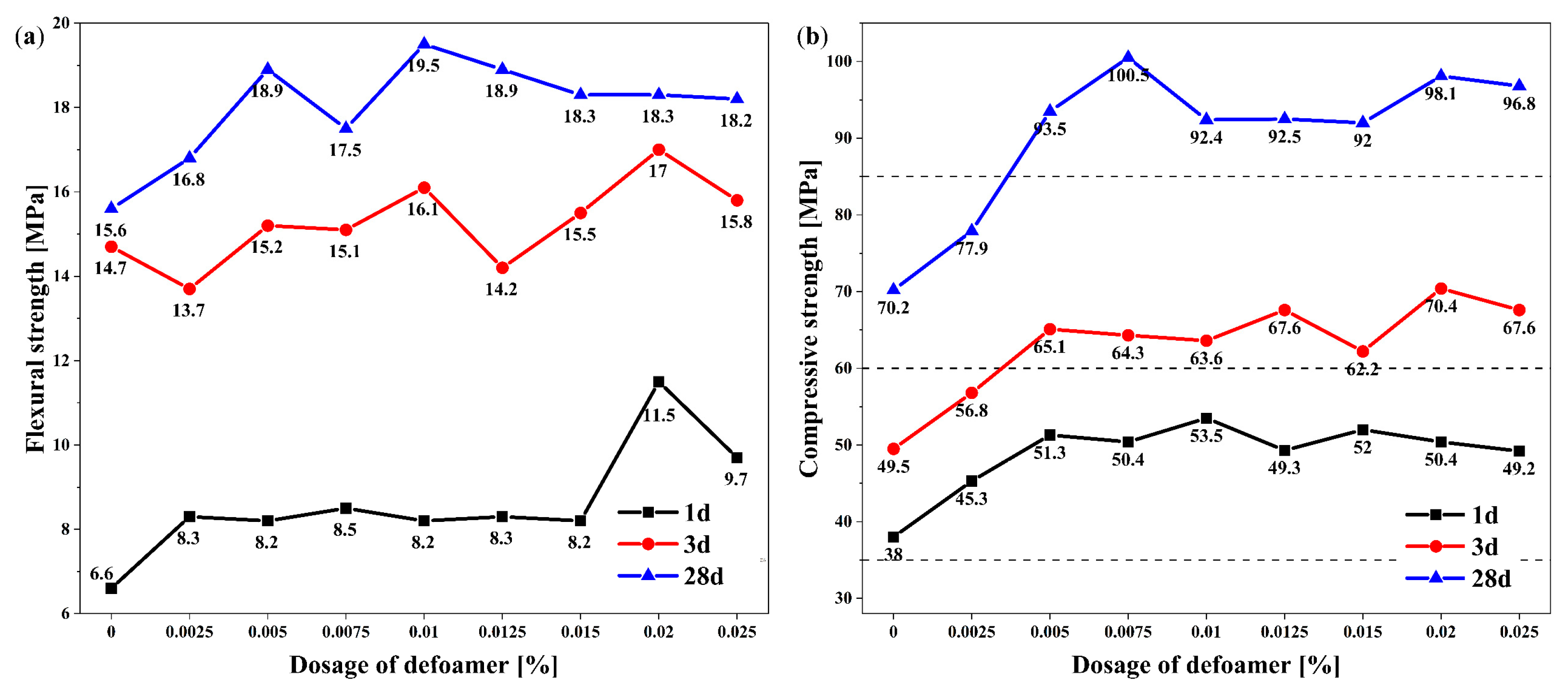
The influence of defoamer on the strength of the grouts at 1 d, 3 d and 28 d is shown in Figure 3. It can be seen from Figure 3 that, with the exception of the flexural strength at 3 d, the flexural strength and compressive strength of all the grouts mixed with defoamer were higher than those without defoamer. When the dosage of defoamer increased from 0 to 0.025%, the flexural strength and compressive strength of the grouts at all ages generally increased initially and then tended to stabilize. Compared with the grouts without defoamer, when the dosage of defoamer was 0.005%, the compressive strength of the grouts at 1 d, 3 d and 28 d increased by 35%, 31.5% and 33.2%, respectively. When the dosage of defoamer was 0.0075%, the compressive strength at 28 d was 43.2% higher than that of the grout without defoamer. Therefore, the optimal dosage of defoamer was 0.005%. Furthermore, when the dosage of defoamer was greater than or equal to 0.005%, the compressive strength at 3 d and 28 d was greater than 60 MPa and 85 MPa, respectively, which meets the requirements of the Chinese standard JG/T 408-2019. It can be seen that the defoamer plays a very significant role in improving the strength of grouts. In addition, the influence of the defoamer on the strength of grout is limited; in other words, it is not a case of the higher the amount of defoamer, the higher the strength, but rather the strength relates to the modification of the internal pore structure of grout by the defoamer.

3.4. Influence of Defoamer on Grout Pore Structure

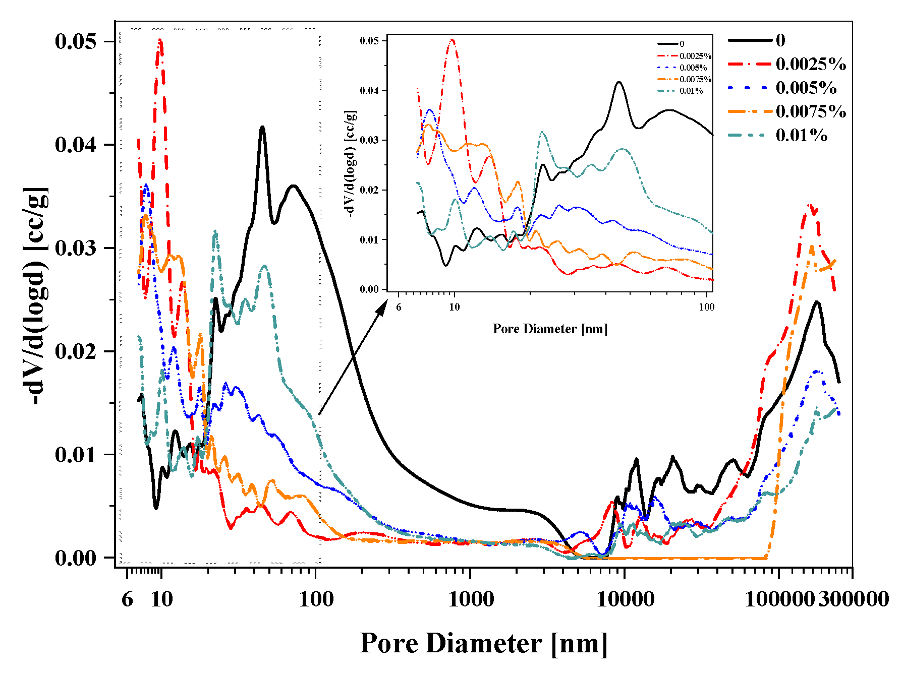
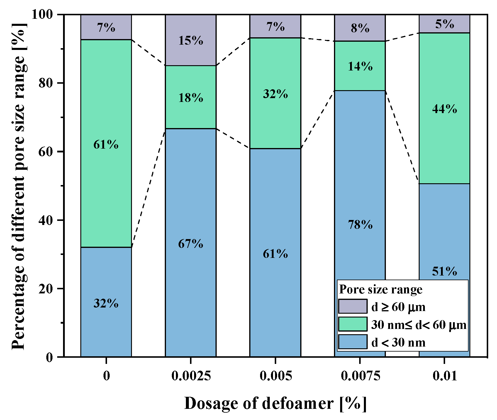
Following the MIP tests, Figure 4 presents the pore size distribution in the range of 6 nm to 300 μm for the grout specimens without defoamer and with defoamer admixtures of 0.0025%, 0.005%, 0.0075% and 0.01%. In the pore size range from 6 nm to 30 nm, the pore volume of the grout with defoamer was generally larger than that of the grout without defoamer. When the dosage of defoamer was 0.0025%, the pore volume was highest, and a very high peak appeared at 10 nm. When the dosage of defoamer was 0.01%, the pore volume was lowest and close to that of the grout without defoamer. In the wide pore size range from 30 nm to 60 μm, the pore volume of the grout without defoamer was almost always the highest of all the grouts, and there were five peaks: two larger peaks at 45 nm and 70 nm and three smaller peaks at 12 μm, 20 μm and 51 μm. The pore volumes of the other four types of grout mixed with defoamer were smaller than those of the grout without defoamer, and the corresponding pore volume peaks were reduced or disappeared completely. It follows that pores in the range from 30 nm to 60 μm can be considered harmful pores, which could reduce the compressive strength of the grout. When the dosage of defoamer was 0.01%, the pore volume was only inferior to that of the grout without defoamer. When the dosage of defoamer was 0.0025% and 0.0075%, the pore volume was relatively small. In the pore size range from 60 μm to 300 μm, all five grouts showed a peak close to 170 μm with the highest pore volume observed when the dosage of defoamer was 0.0025% followed by the grouts with 0.0075%, 0, 0.005% and 0.01% defoamer, in that order. In order to further analyze the influence of defoamer on pore structure, the variation in the regulation of defoamer on different pore size range percentages and the porosity of the grouts is illustrated in Figure 5. The maximum proportion of the pore size range of 30 nm to 60 μm in the grout without defoamer was 61%, whereas a pore structure of 30 nm to 60 μm in the grouts with added defoamer was gradually transformed to a pore structure of less than 30 nm. In particular, when the dosage of defoamer was 0.0075%, the maximum amount of grout with a pore size below 30 nm was 78%, which was more than twice that of the grout without defoamer. However, when the dosage of defoamer increased from 0.0075% to 0.01%, the pore volume below 30 nm decreased to 51%, which was smaller than that of all the grouts mixed with defoamer. The influence of defoamer on the porosity of the grouts is shown in Figure 6. It can be seen that as the defoamer content increases from 0 to 0.01%, the porosity of the grout first decreases and then increases slightly. When the dosage of defoamer increases from 0 to 0.025%, the porosity of the grout decreases by 36.6%, indicating that a low amount of defoamer can significantly reduce the porosity of grouts. As the dosage of defoamer continues to increase, the porosity of the grout slowly decreases. When the dosage of defoamer is at 0.0075%, the porosity is at its lowest. However, when the dosage of defoamer increases from 0.0075% to 0.01%, the porosity of the grout increases by 16.3%. Macropores (>30 nm) in the hardened grouts are more likely to produce weak spots for cracking under loading, which explains the decrease in compressive strength at 28 d and the increase in porosity when the dosage of defoamer is 0.001%. Therefore, in combination with Figure 5, it can be seen that 0.0075% is the optimal dosage with regard to the pore structure of grouts.
The MIP test results relating to the pore structure of grouts can explain the variation in the regulation of grouts. When the dosage of defoamer is 0.0075%, the porosity of grouts is lowest and the corresponding compressive strength at 28 d is the highest.

3.5. Mechanism of Defoamer in Grouts

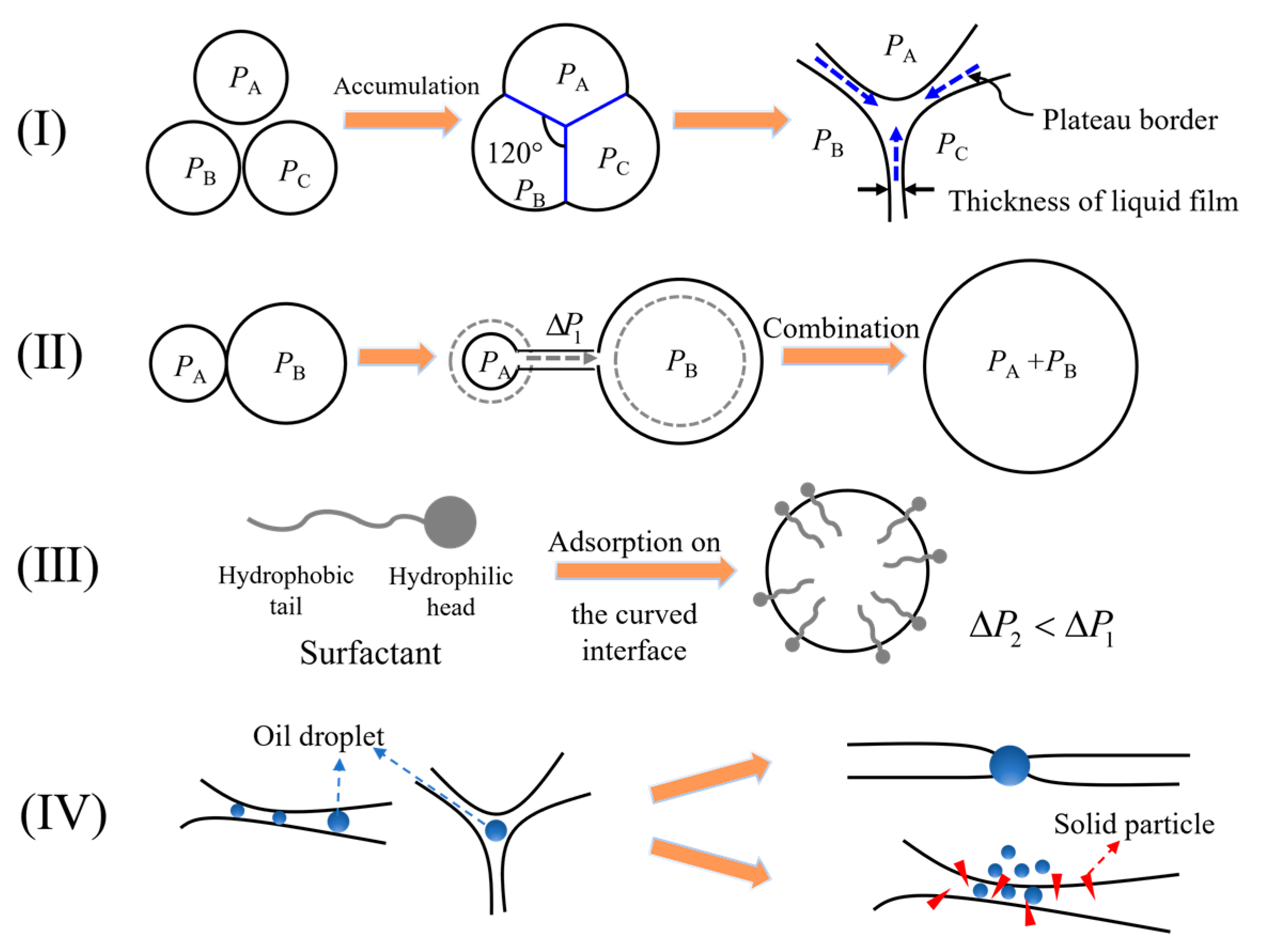
The foams present in the mortar are a system containing a huge surface area and surface energy, and therefore, these foams will accumulate spontaneously to stabilize; the stability of the foams is relative, and the instability is absolute as shown in the foams of I and II in Figure 7 [15,17]. PA, PB and PC are three foams of the same diameter; they will spontaneously accumulate together to reduce their own surface energy, and thus there will be a film of foam called a plateau border between the PA, PB and PC foams. The liquid in the plateau border will converge to the intersection of the foam film thus reducing the thickness of the plateau border, and then the foams achieve accumulation. When there are foams of different sizes, the accumulation between them follows the Laplace equation:
Δ P = 2 γ R
where ΔP is the additional pressure under the curved interface, γ is the surface tension of the liquid phase and R is the radius of curvature of the foam. Because the radius of curvature of the PA and PB foams is different, there is additional pressure under the curved interface, and PA > PB; therefore, the air in the smaller foam runs into the larger foam. However, in fresh grout, the surfactant is attached to the foam surface and exists in the plateau border; this reduces the surface tension in the gas–liquid phase and thus reduces the additional pressure, which extends the life of the foam, i.e., its stability is enhanced as shown in Figure 7, III. In this study, the defoamer used was an oil–solid agent, and there are two main antifoam mechanisms: the antifoam action of oil droplets and the pin effect of solid particles as shown in Figure 7, IV [19,27]. In the grout mixed with defoamer, the oil droplets will connect the two sides of the foam film, that is, form a bridge between them. Subsequently, the equilibrium at the gas–liquid interface is broken by the penetration of the oil droplets, and the foam film is disrupted by the requirements of the laws of capillarity. In addition, the solid particles reduce the barrier for oil droplets to enter the foam film and puncture into the foam film through the pin effect, which destabilizes the three gas–water–oil phases and promotes the movement of the oil droplets.
Defoamer optimizes the pore structure of hardened grout through its defoaming effect as shown in Figure 5. The pore volume of the grout mixed with defoamer is less than that of the grout without defoamer in the range of 30 nm to 60 μm, and the pore volume of the grout below 30 nm increases. Most importantly, the pore structure determines the mechanical strength of the grout [28,29]. Figure 3b and Figure 6 show the influence of defoamer on the pore structure and compressive strength at 28 d, indicating that the lower the porosity, the greater the compressive strength. However, when the defoamer is overmixed, it has a negative effect on the strength of mortar.

4. Conclusions

Grout is a common material in prefabricated construction and is an important component of rebar sleeve-splicing technology. This paper focuses on the influence of a silicone oil-based defoamer on the properties and pore structure of grout. It was found that the introduction of defoamer can eliminate large and harmful foams in the grout. This influence can improve the ball-bearing effect of small foams in the grout to enhance workability, and when the dosage of defoamer was increased from 0 to 0.0025%, the fluidity generally increased initially and then decreased with little change in the loss rate of fluidity. Furthermore, the pore structure of the hardened grouts can be optimized so as to improve the compressive strength. As the dosage of defoamer was increased from 0 to 0.0075%, the compressive strength increased gradually and then remained unchanged or slightly decreased with further addition of defoamer. The optimal dosage of defoamer in the grout was 0.005%~0.0075%. In addition, the mechanism of the silicone oil-based defoamer used in this study was summarized as a model involving the antifoam action of oil droplets and the pin effect of solid particles, which together gradually transform harmful pores larger than 30 nm into pores smaller than 30 nm, resulting in improved porosity. In summary, defoamer is an essential admixture to enhance the mechanical properties of grout, which is of great significance to promote the application of grout in prefabricated construction.

Author Contributions

Conceptualization, C.H. and Z.O.; methodology, Z.O.; validation, C.H., Z.O. and B.D.; formal analysis, B.D.; investigation, R.F.; resources, C.H. and Z.O.; data curation, B.D. and R.F.; writing—original draft preparation, R.F. and Z.O.; writing—review and editing, B.D.; visualization, B.D.; supervision, Z.O.; project administration, C.H. and Z.O. All authors have read and agreed to the published version of the manuscript.

Funding

This research was funded by the National Natural Science Foundation of China (51876087), a Key Project of Hunan Social Science Achievement Appraisal Committee (XSP19ZDI003), a Start-up Fund for Doctoral Research of the University of South China (190XQD047) and Natural Science Foundation of Hunan Province, China (2021JJ50044).

Data Availability Statement

Not applicable.

Conflicts of Interest

The authors declare no conflict of interest.

References

  1. Aslam, M.; Gao, Z.; Smith, G. Exploring factors for implementing lean construction for rapid initial successes in construction. J. Clean. Prod. 2020, 277, 123295. [Google Scholar] [CrossRef]
  2. Luo, T.; Xue, X.; Wang, Y.; Xue, W.; Tan, Y. A systematic overview of prefabricated construction policies in China. J. Clean. Prod. 2021, 280, 124371. [Google Scholar] [CrossRef]
  3. Liu, Y.; Dong, J.; Shen, L. A conceptual development framework for prefabricated construction supply chain management: An integrated overview. Sustainability 2020, 12, 1878. [Google Scholar] [CrossRef] [Green Version]
  4. Pan, W.; Garmston, H. Compliance with building energy regulations for new-build dwellings. Energy 2012, 48, 11–22. [Google Scholar] [CrossRef]
  5. Boafo, F.E.; Kim, J.-H.; Kim, J.-T. Performance of modular prefabricated architecture: Case study-based review and future pathways. Sustainability 2016, 8, 558. [Google Scholar] [CrossRef] [Green Version]
  6. Einea, A.; Yamane, T.; Tadros, M.K. Grout-filled pipe splices for precast concrete construction. PCI J. 1995, 40, 82–93. [Google Scholar] [CrossRef] [Green Version]
  7. Zheng, Y.; Guo, Z.; Guan, D.; Zhang, X. Parametric study on a novel grouted rolling pipe splice for precast concrete construction. Constr. Build. Mater. 2018, 166, 452–463. [Google Scholar] [CrossRef]
  8. Xu, F.; Wang, K.; Wang, S.; Li, W.; Liu, W.; Du, D. Experimental bond behavior of deformed rebars in half-grouted sleeve connections with insufficient grouting defect. Constr. Build. Mater. 2018, 185, 264–274. [Google Scholar] [CrossRef]
  9. Zhou, L.; Li, X.; Yan, Q. Performance of Grouting Sleeve-Connected Prefabricated Beams Subjected to Impact Loading. Buildings 2022, 12, 2146. [Google Scholar] [CrossRef]
  10. Yamada, K.; Takahashi, T.; Hanehara, S.; Matsuhisa, M. Effects of the chemical structure on the properties of polycarboxylate-type superplasticizer. Cem. Concr. Res. 2000, 30, 197–207. [Google Scholar] [CrossRef]
  11. Uchikawa, H.; Hanehara, S.; Sawaki, D. The role of steric repulsive force in the dispersion of cement particles in fresh paste prepared with organic admixture. Cem. Concr. Res. 1997, 27, 37–50. [Google Scholar] [CrossRef]
  12. Lei, L.; Hirata, T.; Plank, J. 40 years of PCE superplasticizers-History, current state-of-the-art and an outlook. Cem. Concr. Res. 2022, 157, 106826. [Google Scholar] [CrossRef]
  13. Tunstall, L.E.; Ley, M.T.; Scherer, G.W. Air entraining admixtures: Mechanisms, evaluations, and interactions. Cem. Concr. Res. 2021, 150, 106557. [Google Scholar] [CrossRef]
  14. Alargova, R.G.; Warhadpande, D.S.; Paunov, V.N.; Velev, O.D. Foam superstabilization by polymer microrods. Langmuir 2004, 20, 10371–10374. [Google Scholar] [CrossRef] [PubMed]
  15. Chandan, M.R.; Naskar, N.; Das, A.; Mukherjee, R.; Harikrishnan, G. Deducing multiple interfacial dynamics during polymeric foaming. Langmuir 2018, 34, 8024–8030. [Google Scholar] [CrossRef]
  16. Kim, J.-H.; Robertson, R.E. Prevention of air void formation in polymer-modified cement mortar by pre-wetting. Cem. Concr. Res. 1997, 27, 171–176. [Google Scholar] [CrossRef]
  17. Pugh, R.J. Experimental techniques for studying the structure of foams and froths. Adv. Colloid Interface Sci. 2005, 114, 239–251. [Google Scholar] [CrossRef]
  18. Arandigoyen, M.; Alvarez, J.I. Pore structure and mechanical properties of cement–lime mortars. Cem. Concr. Res. 2007, 37, 767–775. [Google Scholar] [CrossRef] [Green Version]
  19. Denkov, N.D.; Marinova, K.G.; Tcholakova, S.S. Mechanistic understanding of the modes of action of foam control agents. Adv. Colloid Interface Sci. 2014, 206, 57–67. [Google Scholar] [CrossRef]
  20. Suja, V.C.; Kar, A.; Cates, W.; Remmert, S.; Fuller, G. Foam stability in filtered lubricants containing antifoams. J. Colloid Interface Sci. 2020, 567, 1–9. [Google Scholar] [CrossRef]
  21. Mao, W.; Cao, C.; Li, X.; Qian, J.; You, C. Preparation of Magnesium Ammonium Phosphate Mortar by Manufactured Limestone Sand Using Compound Defoaming Agents for Improved Strength and Impermeability. Buildings 2022, 12, 267. [Google Scholar] [CrossRef]
  22. Luo, Y.; Li, B.; Wang, D.; Lv, Y.; Jiang, Z.; Xue, G. Effects of Different Kinds of Defoamer on Properties of Geopolymer Mortar. Buildings 2022, 12, 1894. [Google Scholar] [CrossRef]
  23. JG/T 408-2019; Cementitious Grout for Sleeve of Rebar Splicing. China Architecture & Building Press: Beijing, China, 2019. (In Chinese)
  24. JGJ/T 70-2009; Standard for Test Method of Basic Properties of Construction Mortar. China Architecture & Building Press: Beijing, China, 2009. (In Chinese)
  25. Kim, H.; Jeon, J.; Lee, H.K. Workability, and mechanical, acoustic and thermal properties of lightweight aggregate concrete with a high volume of entrained air. Constr. Build. Mater. 2012, 29, 193–200. [Google Scholar] [CrossRef]
  26. Shah, H.A.; Yuan, Q.; Zuo, S. Air entrainment in fresh concrete and its effects on hardened concrete—A review. Constr. Build. Mater. 2021, 274, 121835. [Google Scholar] [CrossRef]
  27. Luan, X.; Zhang, E.; Chen, Y.; Ma, R.; Gong, K.; Li, W.; Wang, X. Chemically Modified Silicone Oil with Enhanced Tribological and Anti-Foaming Properties. Lubricants 2022, 10, 364. [Google Scholar] [CrossRef]
  28. Silva, D.; John, V.M.; Ribeiro, J.L.; Roman, H. Pore size distribution of hydrated cement pastes modified with polymers. Cem. Concr. Res. 2001, 31, 1177–1184. [Google Scholar] [CrossRef]
  29. Gorzelańczyk, T.; Hoła, J. Pore structure of self-compacting concretes made using different superplasticizers. Arch. Civ. Mech. Eng. 2011, 11, 611–621. [Google Scholar] [CrossRef]
Figure 1. Influence of defoamer on the fluidity and loss rate of grouts at 30 min: (a) fluidity; (b) loss rate of fluidity at 30 min.
Buildings 13 00170 g001
Figure 2. Influence of defoamer on the wet apparent density of grouts.
Buildings 13 00170 g002
Figure 3. Influence of defoamer on the mechanical properties of grouts: (a) flexural strength; (b) compressive strength.
Buildings 13 00170 g003
Figure 4. Influence of defoamer on the pore size distribution of grouts.
Buildings 13 00170 g004
Figure 5. Influence of defoamer on the percentage of different pore size ranges in the grouts.
Buildings 13 00170 g005
Figure 6. Influence of defoamer on the porosity of grouts.
Buildings 13 00170 g006
Figure 7. Foam evolution and the mechanism of defoamer in grouts.
Buildings 13 00170 g007
Table 1. Chemical compositions of the cementitious materials and admixtures/%.
OxidesNa2OSiO2K2OCaOP2O5Al2O3SO3MgOClFe2O3CO2Others
Cement0.1820.610.8557.230.076.673.733.900.050.62-4.09
SF0.5188.662.710.41-0.460.591.95-1.542.81-
CSA0.15914.090.51851.000.07210.8514.130.8720.0332.9484.5010.857
PEA15.400.124-0.042-0.0180.041-0.6400.01883.72-
Table 2. Mix proportions of the grouts.
No.Cement/gSF/gSand A/gSand B/gCSA/gPEA/gST/gPCE/gDefoamer/g%W/B
GJ145624318180200.20.052.500.25
GJ245624318180200.20.052.50.00250.25
GJ345624318180200.20.052.50.0050.25
GJ445624318180200.20.052.50.00750.25
GJ545624318180200.20.052.50.010.25
GJ645624318180200.20.052.50.01250.25
GJ745624318180200.20.052.50.0150.25
GJ845624318180200.20.052.50.020.25
GJ945624318180200.20.052.50.0250.25
(W/B is water-to-binder ratio, and binder refers to cement and SF).
Disclaimer/Publisher’s Note: The statements, opinions and data contained in all publications are solely those of the individual author(s) and contributor(s) and not of MDPI and/or the editor(s). MDPI and/or the editor(s) disclaim responsibility for any injury to people or property resulting from any ideas, methods, instructions or products referred to in the content.