Article

Blast Resistance in Sandwich Structures Based on TPMS

1
College of Science, Wuhan University of Science and Technology, Wuhan 430081, China
2
Hubei Intelligent Blasting Engineering Technology Research Center, Wuhan 430081, China
3
Hubei Key Laboratory of Process System Science in Metallurgical Industry, Wuhan 430081, China
*
Author to whom correspondence should be addressed.
Buildings 2023, 13(11), 2835; https://doi.org/10.3390/buildings13112835
Submission received: 16 October 2023 / Revised: 4 November 2023 / Accepted: 10 November 2023 / Published: 12 November 2023
(This article belongs to the Special Issue Structural Performance in Blast Load Scenarios)

Abstract

:
This study analyzes the blast resistance in triple-period minimal surface (TPMS) sandwich panel structures with a cellular structure. The explosion test of the TPMS sandwich panel was carried out, and experimental data verified the effectiveness of the finite element model. Four TPMS configurations, Diamond, Gyroid, IWP, and Primitive, were selected as the core of the sandwich panel to determine the dynamic response process of the TPMS sandwich panel under the action of a blast load. The effects of the thickness of the core material and the explosive charge on the blast resistance in the TPMS sandwich panel were investigated. The results show that the increase in core thickness reduces the blast energy absorption efficiency of the sandwich panel, and the energy resistance in the Diamond configuration sandwich panel is stronger than the other three configurations under the same blast load; the increase in explosive charge significantly increases the displacement of the sandwich panel, and the Gyroid configuration shows better energy absorption effect; different TPMS configurations and panel thickness have a significant effect on the deformation and energy absorption of the sandwich panel under the blast load. The results of this study can promote the application of TPMS sandwich structures in blast-resistant structures.

1. Introduction

Sandwich structures have received a lot of attention from researchers because of their good structural stability, high strength, and strong energy absorption capacity [1,2,3]. In the construction field, with various safety accidents, more and more buildings and structures are considering the blast resistance performance of the structure, and research [4,5,6] shows that sandwich panel structures can be effective in absorbing the blast energy. Now, the main sandwich structures are foam structures [7,8], honeycomb structures [9,10], corrugated structures [11], functionally graded structures [12,13], etc.; these porous structures can occur under the action of the explosive loads of large plastic deformation process, through the collapse of the porous makes the structure more stable, in the local fracture damage occurs before the absorption of a large amount of energy.
The research on the anti-knock performance of the sandwich structure has always been a problem that attracts domestic and foreign scholars to study. Xin Li et al. [14] and A. Neuberger et al. [15] analyzed the mechanical behavior of solid panels and sandwich panels under dynamic loads through explosion experiments and in the experiments and simulations of A. Neuberger et al. Compared with the sandwich panel, the results show that the sandwich panel has more excellent anti-blast performance under the action of explosion load under the same weight. Zhu et al. [16] and Fan et al. [17] studied the effects of sandwich panel thickness, sandwich unit size, sandwich panel thickness, and explosive charge on the dynamic response of sandwich panels through explosion experiments. Kun Liu et al. [18] proposed a predictive calculation method for the dynamic response of metal sandwich structures under explosive loads and considered the influence of panel aspect ratio, core layer height, panel thickness, and other parameters on the dynamic response in this method. Shivdayal Patel et al. [19] proposed a new type of hybrid composite material honeycomb sandwich structure. Under the same explosion conditions, the proposed new sandwich structure has better Explosive performance, with smaller deflection changes during response. At present, the anti-knock performance research of sandwich structures is mainly to design the geometric parameters of the sandwich structure, and the type of core material [7,9,10,11,12,19] is one of the key parameters to be considered in the anti-knock design.
Recently, a three-dimensional spatial unit structure minimal surface (TPMS) has attracted the attention of researchers, as its surface curvature is 0 everywhere, and its smooth surface makes the structure eliminate stress concentration effect and has good overall stability, which can be used as an excellent lightweight unit structure, as shown in Figure 1. With the popularity of 3D printing [20], TPMS structures have found a large number of applications in various industries [21,22,23,24,25,26,27,28,29] due to their customizable density, porosity, and cell size [30,31], especially in structural energy absorption [28,32].
The energy absorption effect of the structure is mainly reflected in the absorption of load energy such as static pressure, collision, impact, explosion, etc. For example, Heran Jia et al. [22], Zhu Huaiming et al. [32], and Hanfeng Yin et al. [27,33,34] simulated the mechanical behavior of the TPMS structure under axial load based on static pressure experiments and simulations, and the results show that the TPMS structure has good axial compression performance. Al-Ketan et al. [20,35,36] found that the changes in unit volume fraction, plate thickness, and cell shape had a great influence on the mechanical properties of the structure, and the TPMS sheet structure showed better mechanical properties than the skeleton structure and support structure in compression experiments. The smooth surface of the structure and the stable failure mechanism under compression conditions are important reasons why TPMS structures are applied to all walks of life [37,38]. Ramos Henrique et al. [24] and Novak Nejc et al. [23,39,40] also studied the dynamic mechanical behavior of TPMS structures at different strain rates; TPMS structures exhibit better mechanical properties under impact conditions than traditional porous structures. In the above research, most of the experimental design is based on uniaxial compression and drop weight impact, and the deformation effect and energy absorption effect of the structure is evaluated, and the production of TPMS structure mainly uses an additive system [41], and the stress–strain distribution problem in the deformation process of the structure is studied by finite element method. For example, Duan et al. [42] studied the deformation mechanism of 3D-printed foam structures under dynamic loading and the mechanical behavior of the structure under quasi-static action. These methods and conclusions provide important guidance on the experimental design direction for the performance study and structural optimization [33] of TPMS structures.
TPMS structures are gaining attention, so there is a need for a more comprehensive and in-depth study of the various mechanical behaviors of TPMS structures to allow the performance of TPMS to be fully exploited. The blast resistance performance of the structures has an important significance in the applications in society. Currently, the research on TPMS structure is mainly based on static pressure and general impact studies, while there are few studies on explosion response at high strain rates [39]. In this paper, we will study the dynamic response mechanism and deformation damage process of TPMS structure under blast load and the absorption effect of blast energy.
In this study, the dynamic response process of TPMS and the energy absorption effect were investigated using a typical sandwich panel structure. The blast resistance performance of four types of TPMS sandwich panels, Diamond, Gyroid, IWP, and Primitive, were compared at different panel thicknesses and different explosive amounts, and finally, the results of the orthogonal experiments were optimized using the Taguchi method. The main purpose of this paper is to obtain the difference in the explosion impact protection performance of four different types of TPMS sandwich panel structures and to obtain the TPMS type with the best explosion resistance and the corresponding plate thickness through multivariate optimization. Finally, through the research results of this paper, the TPMS sandwich panel structure is considered to be applied to the building structure so that the general building can protect the structure from damage to the greatest extent in the face of explosion, impact, and other threats.
The innovation of this paper lies in the simulation and analysis of the mechanical behavior of four types of TPMS sandwich panel structures under explosion conditions, which has a new understanding of the dynamic response process of TPMS structures under explosion impact, which provides reference significance for the research of explosion impact protection of TPMS structures.

2. TPMS Explosion Experiment

2.1. TPMS Unit Design

The TPMS structure consists of smooth and continuous surfaces with zero curvature at all points of the surface, and as a porous structure described by implicit functions, TPMS has strong designability. Currently, the most studied TPMS structures are mainly Diamond, Gyroid, IWP, Primitive, and other configurations [27,43,44], and the three-dimensional implicit level set functions of the four TPMS structures used in this paper are:
F D ( x , y , z ) = sin ( ω x ) sin ( ω y ) sin ( ω z ) + cos ( ω x ) cos ( ω y ) cos ( ω z ) + sin ( ω x ) cos ( ω y ) cos ( ω z ) + cos ( ω x ) cos ( ω y ) sin ( ω z )
F G ( x , y , z ) = sin ( 2 π x ) cos ( 2 π y ) + sin ( 2 π y ) cos ( 2 π z ) + sin ( 2 π z ) cos ( 2 π x )
F I W P ( x , y , z ) = 2 [ cos ( 2 π x ) cos ( 2 π y ) + cos ( 2 π y ) cos ( 2 π z ) + cos ( 2 π z ) cos ( 2 π x ) ] [ cos ( 2 2 π x ) + cos ( 2 2 π y ) + cos ( 2 2 π z ) ]
F P ( x , y , z ) = cos ( 2 π x ) + cos ( 2 π y ) + cos ( 2 π z )
The geometric model of the implicit function described above is generated by a MATLAB subroutine, the model is exported in a typical STL format, and the generated model is imported into the Hypermesh software for further processing through the cell array. Finally, various model sizes required for numerical simulation were obtained. It is important to note that the TPMS structure is a unit structure, and the final geometry is made up of many identical TPMS elements, so the final geometry should be an integer multiple of the smallest TPMS element.

2.2. Explosion Experiment System

The explosion test is carried out in an explosive tank specially designed to study the anti-explosion performance of various structures under explosive shock loads, as shown in Figure 2. The effective experimental space in the explosion tank is Φ2000 × 3500 mm, which can carry out TNT explosion experiments up to 1.0 kg and is equipped with a special observation window and a strong light source, which can be photographed and recorded using a high-speed photographic system. The tank is equipped with a special cable hole through which the sensor connection wire can be removed. Equipped with special exhaust ventilation equipment, after the explosion produces a large number of toxic smoke and toxic gas, it can be quickly eliminated to ensure the respiratory safety of the experimenters.

2.3. Experimental Model Design

Due to its particularity, TPMS structure cannot be combined or welded from existing structures, and this experiment uses 3D printing technology to generate TPMS sandwich layer structure [45,46], as shown in Figure 3. The sandwich layer is bonded with glue with the top and bottom panels, and the bonding strength is low, which is negligible during the explosion impact test. In order to simulate the real environment of the sandwich panel at the time of the explosion, a fixed constraint is adopted around the sandwich panel, and the top and bottom steel plates are used to clamp the surrounding edges of the TPMS sandwich panel, and the steel plate is fixed by a double-ended threaded rod.
The charge consists of a digital electronic detonator and a 2# rock emulsion explosive, which is wrapped in a film and attached to the column of the digital electronic detonator. Because the industrial digital electronic detonator has a concentrating hole at the end of the production, if the concentrating point is facing the TPMS sandwich panel, the explosion jet will directly destroy the panel of the sandwich panel. Therefore, the digital electronic detonator is placed horizontally during the experiment, as shown in Figure 4, to avoid the sandwich panel from being affected by the concentrating jet, forming a more concentrated hole, which is conducive to experimental test comparison.

2.4. TPMS Sandwich Panel Anti-Explosion Effect

Under the action of the explosion load, the deformation mode of the TPMS sandwich panel is funnel-shaped. That is, the displacement deformation from the closest point of the explosion source is the largest, and the deformation spreads in an arc to the surroundings, as shown in Figure 5. With the increase in charge dose, the deformation of the Diamond-type TPMS sandwich panel gradually increases, and the deformation becomes a cone-type when the dose is small, and after the amount of drug increases, the deformation changes to an ellipsoidal-type.
According to the failure mode of the TPMS sandwich panel after the explosion, the sandwich panel can be divided into three areas: (1) complete failure zone, (2) partial structural fracture zone, and (3) plastic deformation zone, as shown in Figure 6. The complete failure zone is the closest to the center of the explosives. After the explosion, there is a significant hole in the center of the sandwich panel, the top panel and the core layer are completely damaged. In the partial structural fracture zone, due to the incomplete support of the core structure, the deformation of the point directly supported by the core layer is smaller than that of the point directly supported by the core layer, and the macroscopic performance is that the surface of the sandwich panel has a point-like protrusion, as shown in the red area in Figure 6. The core layer should be partially ruptured by the impact of the explosion, but the overall structure remains intact. In the plastic deformation zone, due to the good tensile properties of the aluminum alloy material, the sandwich panel only underwent obvious plastic deformation in this area, and there was no destructive change often.

3. Model Building and Validation

3.1. Simulation Model Introduction

In order to gain a deeper understanding of the large deformation mechanism and mechanical properties of TPMS structures under explosive loading, numerical simulations of the above-mentioned TPMS structures with different configurations and geometric parameters were carried out in this study using LS-DYNA explicit dynamics software. The LS-DYNA R11 solver is used to solve correlated computational models.
The TPMS finite element model obtained by Hypermesh software, according to the characteristics of the structure, the TPMS structure consists of shell units, and a 1 mm thick thin panel is added to the top and bottom of the TPMS structure to form a sandwich structure, the shape and the size of the sandwich panel are shown in Figure 7, the shape of the panel rectangular body, the size of 20 cm × 20 cm × 2.2 cm, the TPMS unit size is 2 cm × 2 cm × 2 cm. Therefore, in the computational model in this paper, each model consists of 100 TPMS base elements tiled together in the XY plane, and the sandwich layer has only one layer of TPMS base elements in the thickness direction.
In this paper, we mainly study the TPMS structure with different configurations and sheet thicknesses. (1) TPMS sandwich panels of the unit types shown in Equations (1)–(4) are constructed by means of arrays to consider the blast resistance in different TPMS unit structures; (2) we consider the blast resistance in TPMS sandwich panels with different sheet thicknesses by constructing TPMS units of 1 mm, 2 mm, and 3 mm thicknesses; (3) the TNT charge diameter of 1.5 cm, 2.0 cm, and 2.5 cm, respectively, to consider the blast resistance in TPMS sandwich panels with different explosive quantity. Table 1 shows the full calculation conditions for this paper. Figure 7 depicts the process and method of the whole experiment.

3.2. Material Model

AISI 4340 Aluminum alloys have been widely used in construction, transportation, and aerospace due to their low density, high strength, and high plasticity [16]. The same aluminum alloy material is used in the model for both sandwich core and top and bottom plates, and a bilinear elastic–linear model (*MAT_PLASTIC_KINEMATIC) is used to describe the stress–strain process of aluminum alloy, according to the literature [47] without considering the strain rate effect of the material. The material parameters of the aluminum alloy are given in Table 2.
The explosive uses a high-energy explosive model (*MAT_HIGH_EXPLOSIVE_BURN), and the JWL equation of state shown in Equation (5) describes the relationship between the pressure and volume of the explosive during the explosion.
p = A ( 1 ω R 1 V ) e R 1 V + B ( 1 ω R 1 V ) e R 2 V + ω E s V
where p is the burst wave pressure, V is the initial relative volume, A, B, ω, R1, R2 is the equation of state constant, according to the literature [10] to obtain the material parameters related to TNT explosives shown in Table 2.
The air is filled with a blank material model (*MAT_NULL) and described using the linear polynomial equation of state shown in Equation (6).
p = ( C 0 + C 1 μ + C 2 μ 2 + C 3 μ 3 ) + ( C 4 + C 5 μ + C 6 μ 2 ) E 0
where C0 ~ C6 are constants; E0 is initial internal energy per unit volume; μ = 1/(V − 1), where V represents the relative volume.

3.3. Explosive Loads and Boundary Conditions

Unlike static loading, the explosion load will cause the model structure to produce a high strain rate dynamic response [48], and the explosive explosion in the near zone will produce a smash zone; the structure will suffer complete damage in this range, outside the smash zone will produce partial fracture and plastic deformation zone, the structure in the region no longer remain intact, the strong effect of the explosion wave in part of the structure plastic deformation, and in the more distant zone structure will also be subject to the effect of the explosion wave, resulting in a certain deformation and thus absorb part of the energy generated by the explosion.
In this paper, the force transfer process between the explosive explosion and the TPMS sandwich plate is established by using the flow-solid coupling [49], and the size and location of the explosive are constructed using the initial volume method. To study the effect of the bare explosion on the TPMS sandwich panel, the TNT spherical charge package is therefore arranged at a distance of 4.5 cm from the top surface of the sandwich panel, as shown in Figure 7.
In order to study the anti-knock energy absorption effect of the TPMS structure, the boundary conditions shown in Figure 8 were adopted, and the form of full constraint was adopted for the surrounding area of the sandwich panel. Equations (7) and (8) represent the displacement boundary conditions and stress boundary conditions, respectively (a = b = 20 cm).
u ( x = 0 ) = 0 , u ( x = a ) = 0 , v ( y = 0 ) = 0 , v ( y = b ) = 0
σ x x ( x = 0 ) = σ x x ( x = a ) = 0 , σ y y ( y = 0 ) = σ y y ( y = b ) = 0

3.4. Structural Blast Resistance Parameters

In order to accurately quantify the blast resistance in a structure, several metrics are usually used [22,50]: maximum displacement, total energy absorption (EA), specific energy absorption (SEA), and mean crash force (MCF) for the evaluation of thin-walled structures.
Maximum displacement is the structure in the explosion load under the action of the structure at a point of maximum displacement value; the value represents the maximum deformation point and damage location of the structure that may exist.
EA is the total energy absorbed by the structure under the blast load. In finite elements, the absorbed internal energy of the unit is calculated as the six tensor components in the one-point stress state of the unit:
{ Δ I ( k ) = W ( k ) V ( k ) W ( k ) = 1 2 σ ( k ) T ε ( k )
where W is the strain energy density, V is the cell volume, and the stress vector σ(k) and strain vector ε(k) are defined respectively as
{ σ ( k ) = [ σ x x ( k ) , σ y y ( k ) , σ z z ( k ) , σ y z ( k ) , σ x z ( k ) , σ x y ( k ) ] ε ( k ) = [ ε x x ( k ) , ε y y ( k ) , ε z z ( k ) , γ y z ( k ) , γ x z ( k ) , γ x y ( k ) ]
A structure that absorbs energy well maintains its mass in a lighter state while absorbing energy, so the SEA is used as the parameter to describe this state:
S E A = E A m
where m is the mass of the thin-walled structure, and SEA is the energy absorbed per unit mass of the thin-walled structure.
MCF is the ratio of energy to displacement, expressed as
M C F = E A L
where L is the displacement of the thin-walled structure, expressed here as the average value of the displacement of the top and bottom plywood of the structure.

4. Results and Discussion

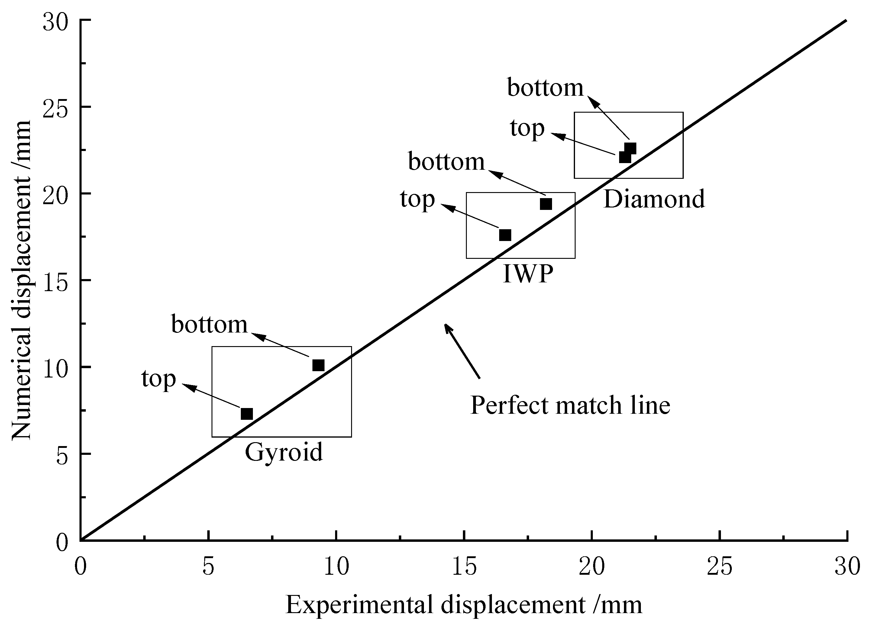
4.1. Simulation Model Validation

In order to verify the finite element model, the bursting performance of TPMS sandwich panels was tested. The experiment uses the same boundary conditions as the finite element model: the center of the charge is 4.5 cm from the panel on the sandwich panel, the charge is composed of one detonator and 9 g 2# rock emulsion explosive, and the experimental arrangement is shown in Figure 4.
According to the conversion ratio of emulsion explosive to TNT explosive yield, the explosive effect of the experimental pack and the emulsion explosive is equivalent to 7.3 g TNT, which is equivalent to the amount of TNT with a diameter of 2 cm in the finite element model. The explosion of explosives directly in the air will produce a loud sound, and there is a risk of injuring people by explosive fragments, so the experiment is carried out in a special explosive container.
Compared with the displacement of the top and bottom panels of Gyroid, IWP and Diamond sandwich panels with a thickness of 1 mm, a sandwich layer thickness of 10 mm, and a panel thickness of 1 mm, the displacement of the top and bottom panels of Gyroid, IWP and Diamond under the action of explosion load can be seen from Figure 9, the data points are close to the perfect matching line, and the deformation of the top and bottom panels of different types of sandwich panels is 6.5 mm, 9.3 mm, 16.6 mm, 18.2 mm, 21.3 mm, and 21.5 mm respectively under the same dosage. The predicted values of numerical calculation are 7.3 mm, 10.1 mm, 17.6 mm, 19.4 mm, 22.1 mm, and 22.6 mm; as can be seen from the figure, the simulation calculation results are in good agreement with the experimental results. The finite element calculation model adopted in this paper can accurately describe the dynamic response and deformation mode of the TPMS sandwich panel structure under explosion load.

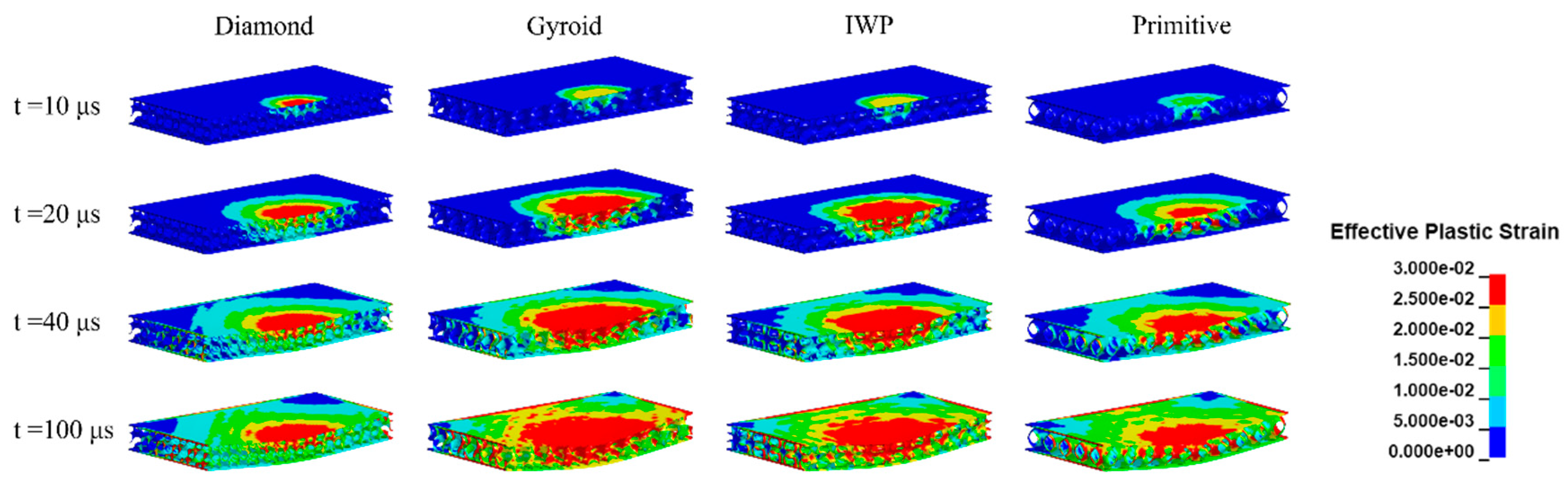
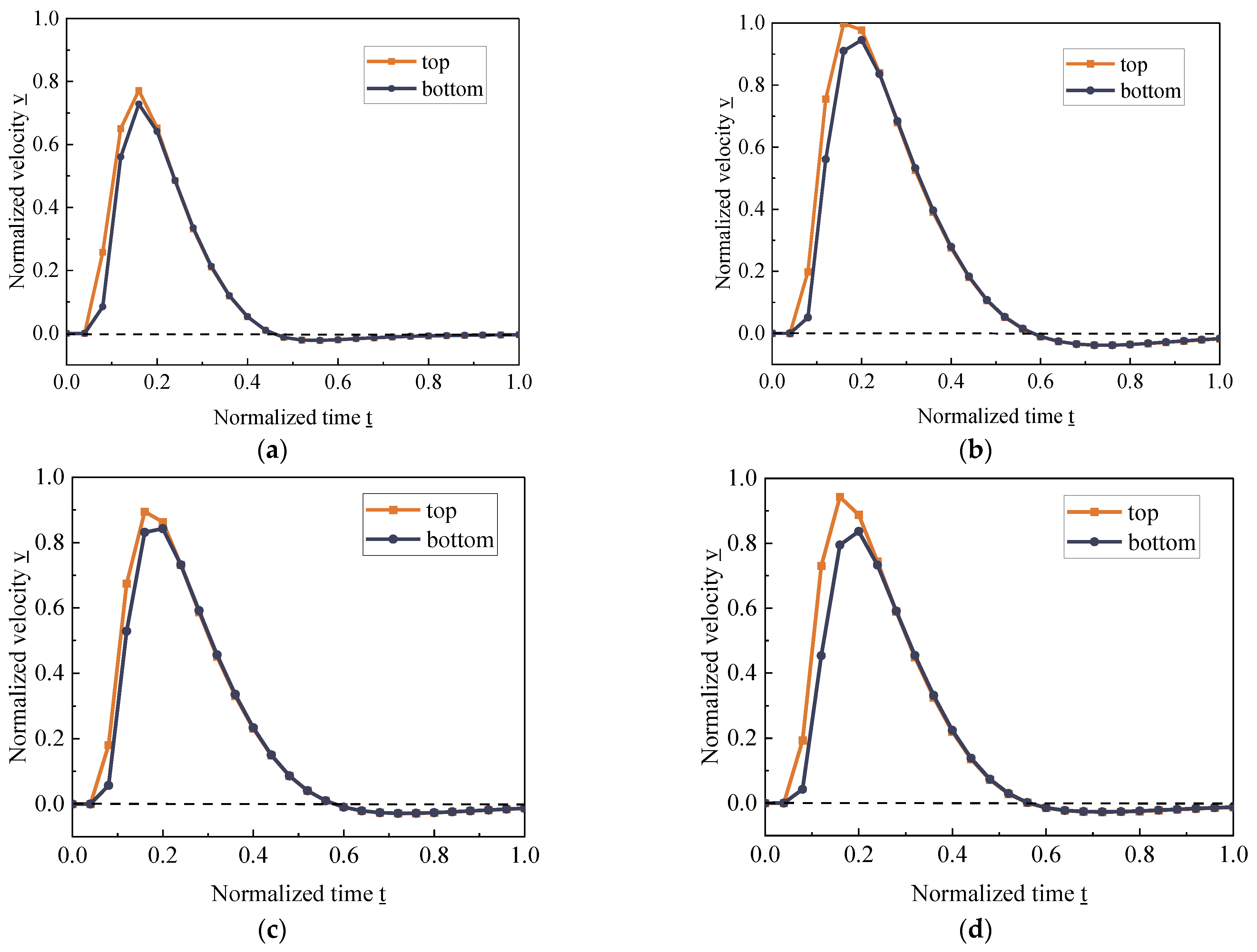
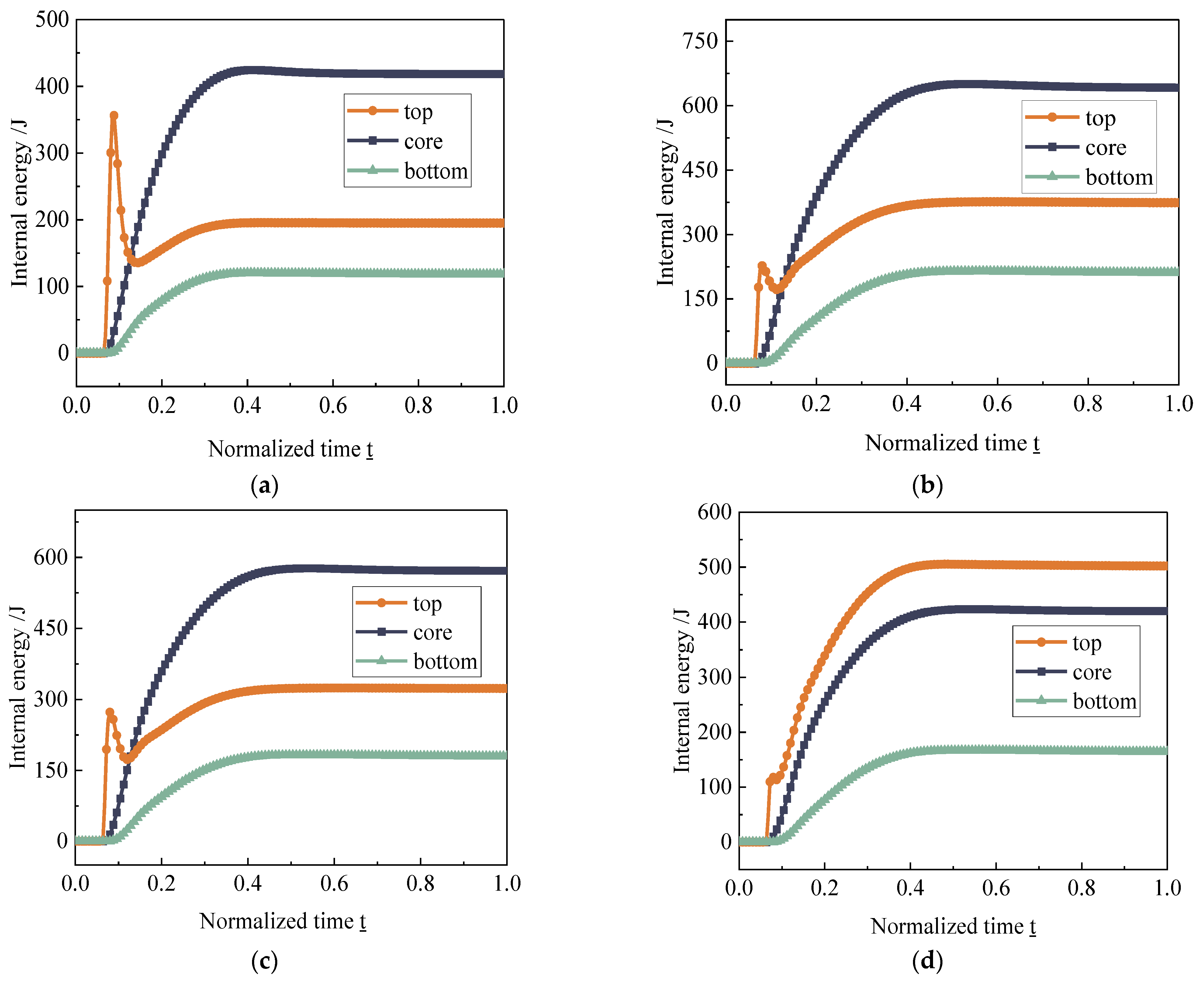
4.2. TPMS Dynamic Response Process

The mechanical behavior of the structure is mainly expressed as the dynamic response process and deformation mechanism under the blast load. Four types of TPMS sandwich panels of the same material show different deformation characteristics and magnitudes under the action conditions of the blast load of a 2.5 cm diameter spherical TNT package; the thickness of the top and bottom panels of the sandwich panel is 1 mm, the thickness of the TPMS sandwich sheet is 1 mm, and the thickness of all four types of TPMS panels are kept consistent. Under the action of blast load, the deformation of each TPMS sandwich plate is shown in Figure 10, and the 1/2 model is taken along the axial direction. According to the equivalent plastic strain change cloud diagram, it can be seen that the effect of absorbing blast energy by plastic deformation of the sandwich plate is obvious.
In Figure 10, after the detonation of the package, a 10 μs blast wave reaches the center of the panel. The panel is orthogonally anisotropic due to the array of TPMS units, and the spherical blast wave forms a circular plastic deformation zone in the plane of the panel. At 20 μs, the plastic deformation zone expands further and causes partial displacement in the axial direction of the panel. At 40 μs, the plastic deformation zone has been extended to the edge region of the panel, and there is a significant change in the deflection of the panel. After 100 μs, the tendency of further deformation of the panel is no longer significant and tends to be stable. The shapes of the plastic deformation zones of the four TPMS sandwiches were basically similar, and the deformation of all four corners of the panels was smaller. The comparison revealed that the overall plastic deformation zone of the Diamond configuration was smaller than that of Gyroid, IWP, and Primitive.
To further study the dynamic response process of the TPMS structure under the blast load, Figure 11 depicts the velocity time curves of the top and bottom sandwich panels after normalization. From Figure 11a–d, it can be seen that in the initial stage of a TNT package explosion, the velocities of both the top and bottom plates of the sandwich plate are 0 because the blast wave has not yet been transmitted to the sandwich plate structure, which macroscopically shows no deformation of the structure; the blast wave reaches the top surface of the sandwich structure at t = 0.04, and the velocity of the top plate reaches its maximum at t = 0.16. Sandwich panel top and bottom plate velocities in a certain range are not consistent; the movement speed of the top plate is greater than the movement speed of the bottom plate, which, in the macroscopic performance of the sandwich layer, is compressed. After that, the top and bottom plates decay to the same velocity, moving together until the velocity decays to 0. The macroscopic performance is that the core no longer continues to be compressed or stretched, and the core plate moves down together as a whole until the plate is no longer deformed.
Figure 12 depicts the energy absorption process of the TPMS sandwich panel under the blast load. The internal energy of each part of the Diamond, Gyroid, and IWP sandwich structures in Figure 12a–c increases rapidly with time, and the top plate reaches the first peak at around t = 0.08. The internal energy of the top plate increases at a slower rate after decreasing until it reaches the final peak internal energy; the final peak internal energy of Diamond, Gyroid, and IWP are 195.43 J, 650.61 J, and 324.34 J. It is worth noting that the final internal energy of the top of the Diamond plate in Figure 12a is less than the first internal energy peak of 356.86 J. Although the internal energy change history of the Primitive top plate in Figure 12d is similar to other structures, the final internal energy of the top plate is 505.20 J, which is larger than the internal energy of the core of 423.34 J, while the internal energy of core of other structures is eventually larger than the internal energy of top plate.
The final internal energy of each part in Figure 12 represents the energy absorption capacity of the structure under the blast load. The total internal energy of the Diamond, Gyroid, IWP, and Primitive configurations of sandwich panels were 732.71 J, 1227.36 J, 1075.62 J, and 1087.44 J, respectively, when the internal energy of the top and bottom panels and the core of the sandwich panel were summed. This indicates that the Diamond configuration absorbs less energy than the other three structures under the same TNT mass explosion with a thickness of 1 mm, and the Gyroid configuration absorbs the most energy, which corresponds to the fact that the equivalent plastic strain region of the Diamond configuration is smaller than the other structures and the equivalent plastic strain region of the Gyroid configuration is the largest in Figure 10.
Figure 13 shows the change process of the displacement of the top and bottom plates of the sandwich panel. In the initial stage, the displacement of the bottom plate has an obvious lag phase with a lag time of about 20 μs, during which the TPMS sandwich structure becomes unilateral compression. After that, the top and bottom plate centers are displaced together, but the displacement speed of the center unit of the top plate is greater than that of the bottom plate. After 200 μs, the structure stabilizes, and the displacement no longer changes significantly. In Figure 13a–d, the displacement of the top and bottom plates of the Diamond structure is the smallest, only 7.59 mm and 6.54 mm, while the displacement of the Gyroid structure is the largest, with a maximum displacement of 13.35 mm for the top plate and 10.89 mm for the bottom plate. The magnitude of the maximum displacement means the strength of the core plate’s ability to maintain deformation under the blast load. Among the four TPMS structures, the Diamond structure is more capable of maintaining its structural stability under the blast load.
The difference between the final displacement of the top and bottom plates represents the deformation of the sandwich layer, and the deformation varies for different sandwich layers. In Figure 13a,c,d, the displacement trends of the top and bottom plates of Diamond, IWP, and Primitive structures are the same, the recovery of deformation after reaching the maximum displacement is small, and the final deformation of the sandwich layer is 1.41 mm, 2.26 mm, and 2.68 mm, respectively. The deformation of the Diamond sandwich layer is the smallest. The final deformation of the core in Figure 13b is 2.68 mm, which is consistent with the deformation of the Primitive core, but the Gyroid structure differs from the other structural displacements in that there is a significant recovery phase of the bottom plate displacement.

4.3. Influence of Sheet Thickness

The variation in sheet thickness directly affects the quality of the sandwich panel. The same explosive mass and specifications were used to compare the effect of TNT package explosion on the structure of different sheet thicknesses. The mass of the spherical TNT with a diameter of 2.0 cm is 6.9 g. The distance between the top panel of the sandwich and the explosion source is 4.5 cm. The maximum displacement of the top and bottom panels was used to evaluate the deformation capacity of different TPMS structures under the action of blast load.
Figure 14 depicts the maximum displacements of the top and bottom plates of the four TPMS configurations with sheet thicknesses of 1 mm, 2 mm, and 3 mm. Respectively, the maximum displacements of the top plate of the same sandwich panel are greater than the maximum displacements of the bottom plate. With the increase in sheet thickness, the top plate displacements of Diamond, Gyroid, IWP, and Primitive configurations decreased by 73.89%, 66.41%, 66.45%, and 45.19%. This indicates that the resistance to deformation of the structure increases with the increase in sheet thickness, and the blast resistance in the Diamond configuration is most obviously affected by the sheet thickness. The resistance to deformation under the blast load increases with the increase in sheet thickness for the Primitive configuration, but the enhancement effect is not as good as the other three sandwich structures.
Figure 15 shows the comparison of the deflection of the top plate of four TPMS sandwich structures with different sheet thicknesses under the blast load. The deflection variation produced by the spherical wave generated by the blast acting on the axial direction of the sandwich has a strong symmetry and shows a funnel shape in the three-dimensional space. The closer to the explosion source, the greater the deflection, which is related to the propagation and attenuation of the blast wave in space; the closer the distance, the smaller the blast wave attenuation, and the greater the peak load. The deflection curve is a “top convex” shape; that is, the near area of the explosion spreads outward when the deformation of the near area decays fast, and the far area decays slowly, which can be explained in the blast shock wave propagation equation:
p = f ( Q 3 R )
where p is the shock wave pressure, f is the attenuation coefficient, Q is the amount of explosive, and R is the distance to the source of the explosion; as R increases, the decay of p becomes slower, so the deflection curve in the far region of the explosion becomes smoother.
Figure 16 shows the distribution of energy absorption in different configurations with different sheet thicknesses. The sandwich core is the main part of energy absorption, and the energy absorption distribution of various sheet types and thicknesses of the sandwich core’s energy absorption ratio is more than 50%. With the increase in thickness, the energy absorption ratio of the sandwich core shows an increasing trend, and the energy absorption ratio of both the top and bottom plates shows a decreasing trend. The total energy absorbed by the sandwich panel also gradually decreases with the increase in the thickness of the sheet, which indicates that the plastic deformation of the sandwich panel under the blast load decreases with the increase in the sheet thickness. The Diamond configuration has a weaker ability to absorb blast energy than other configurations of sandwich panels, which is positively related to the size of its deformation under blast load.
The SEA values of the sandwich core are given in Figure 17, and the comparison shows that the Diamond configuration has the smallest SEA at the same sheet thickness. The smallest SEA (71.75 J/kg) was obtained for the Diamond configuration at the sheet thickness of 3 mm, and the largest SEA (872.06 J/kg) was obtained for the Gyroid configuration at the sheet thickness of 1 mm, indicating that the Gyroid configuration has better energy absorption capability under the blasting. Comparing different sheet thicknesses, it was found that the SEA values of all types of TPMS structures showed a decreasing trend with increasing thickness, indicating that the increase in sheet thickness, which increases the mass of the structure, is not certainly beneficial to the energy absorption effect of the structure.
Figure 18 compares the mean crash force (MCF) for different sheet thicknesses. The MCF values of the TPMS sandwich increased with the increase in sheet thickness. The MCF of Diamond, Gyroid, IWP, and Primitive configurations increased by 51.06%, 104.34%, 140.46%, and 55.71% as the thickness increased from 1 mm to 3 mm. The MCF of the IWP configuration increased most significantly, indicating that the ability of the IWP configuration to absorb energy through displacement deformation is more sensitive to the sheet thickness.

4.4. Influence of the Amount of Explosives

Different masses of explosives packet explosion generated by the shock wave and energy to the core plate, the wavefront surface pressure, and the total energy transferred are different. In order to compare the impact of different amounts of explosives on the sandwich panel, the design of 1.5 cm, 2.0 cm, and 2.5 cm diameter of the spherical package. The distance between the explosion center and the top plate is 4.5 cm, and the thickness of the plate is 1 mm.
Figure 19 compares the displacement magnitude of the top and bottom plates of the sandwich panel under different explosive amounts. The increasing diameter of the TNT package causes greater displacement of the top and bottom plates, and this trend is consistent across the four TPMS structures. However, the sensitivity of different TPMS structures to the amount of explosives varies slightly, with the Diamond configuration having the smallest displacement of the top and bottom plates and the Gyroid configuration having the largest displacement of the top and bottom plates at the same amount of explosives. Taking the top plate as an example, the maximum displacements of the top and bottom plates of the structure increased with the increase in the explosive quantity by 656.79%, 453.30%, 419.32%, and 442.14%, respectively. Although the Diamond configuration has the smallest displacement, it is more sensitive to the increase in explosive quantity.
Figure 20 in the deflection curve changes shows that with the increase in the number of explosives, plate deflection also becomes larger, and the deflection curve shows the middle more and more “sharp” trend. That is, the closer the location of the source of explosives to the change in the explosive charge, the greater the impact. The deflection curves of the IWP configuration and Primitive configuration are highly consistent, and both have the same deformation behavior and deformation shape under the blast load. Under the same conditions, the deflection variation in the Diamond configuration is at the smallest level, indicating that the Diamond configuration deforms less under the blast load and resists deformation better than other configurations.
Figure 21 energy distribution shows the energy absorption status of the sandwich panel structure under different explosive charges. With the rapid increase in the explosion energy, the energy absorbed by the structure also increases rapidly and geometrically. The Gyroid configuration is found to absorb more energy (1227.32 J) under the same blast load, while the Diamond configuration has the worst energy absorption capacity (901.41 J) among the four TPMS structures.
Figure 22 demonstrates the energy absorption status of the core plate structure per unit mass of the explosive blast. The diameters of the explosive package are 1.5 cm, 2.0 cm, and 2.5 cm, and the explosion center is 4.5 cm from the sandwich panel. At the same TNT package volume, the Diamond configuration has the smallest SEA, and the Gyroid has the highest SEA, which is consistent with the results in the previous section. At different TNT packet volumes, the SEA values of each structure increased with increasing volume, and the Gyroid configuration achieved the highest SEA value (2068.04 J/kg) at a packet diameter of 2.5 cm. The SEA of the IWP and Primitive conformations were between the Diamond and Gyroid conformations, indicating that the ranking of the SEA of each TPMS structure did not change with an increasing explosive charge. That is, the SEA of the Gyroid configuration is the largest at the same explosive charge.
Figure 23 compares the mean crash force (MCF) produced at each sandwich panel for packet explosions of 1.5 cm, 2.0 cm, and 2.5 cm in diameter. The MCF value of the TPMS sandwich panel monotonically increased with the increase in the explosive charge. The MCF value of the IWP configuration was the largest (71.29 J/mm) at the explosive package diameter of 1.5 cm, and the MCF value of the Diamond configuration became the largest (130.64 J/mm) at the explosive package diameter of 2.5 cm with the increase in the explosive charge. From the increase in MCF value, the effect of energy absorption by displacement of Diamond configuration is more influenced by the explosive charge.

4.5. Multivariate Optimization

In order to comprehensively consider the blast resistance in TPMS sandwich structures with different sheet thicknesses at different explosive charges, Taguchi’s method [51] was used for optimization analysis. Taguchi’s method uses an orthogonal array to design the experiment using the ratio of the mean to the standard deviation defined as the signal-to-noise ratio (S/N) [52], and the signal-to-noise ratio to evaluate the sensitivity of the experimental variable factors to the results. Table 3 shows the orthogonal experimental design scheme for four TPMS sandwich panels using Taguchi’s method.
In the Taguchi method, different target results are expected to correspond to different S/N ratio calculation methods. In this paper, the S/N ratio of displacement is calculated as “smallest is best”, and the S/N ratio of EA, SEA, and MCF is calculated as “largest is best”.
Figure 24 shows a comparison of the signal-to-noise ratio results for the anti-blast energy absorption capacity of each TPMS configuration by classification. According to Figure 24a,d, the effect of sheet thickness variation on TPMS sandwich plate displacement and MCF values was a bit greater, and the effect of TPMS configuration change on sandwich plate displacement and MCF values was similar. According to Figure 24b,c, it was found that both panel thickness variation and TPMS configuration variation had significant effects on EA and SEA values of sandwich panels, and three TPMS configurations, Gyroid, IWP, and Primitive, had approximate effects on EA and SEA and were significantly better than Diamond configuration.
The optimal combinations corresponding to different energy absorption indexes are given in Table 4. It can be found that different TPMS configurations and sheet thicknesses exhibit different effects on the energy absorption performance, and a variety of parameters can be optimally selected according to the design needs.

5. Conclusions

This paper conducted an explosion experiment on a TPMS sandwich panel in a special explosion tank and obtained the deformation mode of the sandwich panel under the explosion load of detonators and emulsion explosives. The experimental results were used to verify the simulation model. A verified simulation model was used to study the dynamic response process, deformation capacity, and energy absorption effect of four types of TPMS structural sandwich panels, including Diamond, Gyroid, IWP, and Primitive, under explosion loads. By changing the thickness of the core layer of the sandwich panel and the volume of explosives, the anti-explosion properties of the above four TPMS sandwich structures were studied. The main conclusions are as follows:
  • The anti-explosion performance of four TPMS structures is studied, which provides a new direction for the research of TPMS sandwich structures, which can be applied to the anti-explosion protection of buildings.
  • Under the action of an explosion load, the absorption of energy of the top plate and the sandwich layer accounted for the main part, the sandwich layer had an obvious compression deformation process, and the structure had a compression densification process. In an actual application process, the thickness of the sandwich layer can be increased to achieve the purpose of protecting the building.
  • When four Diamond, Gyroid, IWP, and Primitive TPMS sandwich panel structures were under the action of explosion load, the Diamond structure had better resistance to deformation, the Gyroid had better energy absorption effect, and the Diamond structure in actual use could avoid structural damage, and Gyroid structure can protect the material of the building.
  • Parametric studies have shown that the TPMS configuration and the corresponding different panel thicknesses play an important role in energy absorption during the explosion, and the increase in panel thickness can enhance the deformation resistance in the sandwich panel during the explosion.

Author Contributions

Conceptualization, T.L.; methodology, D.Z. and L.H.; software, T.L. and Y.P.; validation, H.T. and S.C.; formal analysis, T.L.; resources, L.H.; data curation, T.L.; writing—original draft preparation, T.L.; writing—review and editing, L.H.; funding acquisition, L.H. and D.Z. All authors have read and agreed to the published version of the manuscript.

Funding

This research was funded by Hubei Key Laboratory of Blasting Engineering, grant number BL2021-15; the National Natural Science Foundation of China, grant number 51904210 and 52274136; the Hubei Provincial Key R&D Program, grant number 2020BCA084; Hubei Provincial Key Laboratory of Systems Science in Metallurgical Industry Process, grant number Z202001.

Data Availability Statement

Data are contained within the article.

Conflicts of Interest

The authors declare no conflict of interest.

References

  1. Wang, D. Cushioning Properties of Multi-layer Corrugated Sandwich Structures. J. Sandw. Struct. Mater. 2009, 11, 57–66. [Google Scholar] [CrossRef]
  2. Li, M.; Wu, L.; Ma, L.; Wang, B.; Guan, Z. Mechanical Response of All-composite Pyramidal Lattice Truss Core Sandwich Structures. J. Mater. Sci. Technol. 2011, 27, 570–576. [Google Scholar] [CrossRef]
  3. Dogan, A. Low-velocity impact, bending, and compression response of carbon fiber/epoxy-based sandwich composites with different types of core materials. J. Sandw. Struct. Mater. 2020, 23, 1956–1971. [Google Scholar] [CrossRef]
  4. Kalubadanage, D.; Remennikov, A.; Ngo, T.; Qi, C. Close-in blast resistance of large-scale auxetic re-entrant honeycomb sandwich panels. J. Sandw. Struct. Mater. 2020, 23, 4016–4053. [Google Scholar] [CrossRef]
  5. Wang, Y.; Yu, Y.; Wang, C.; Zhou, G.; Karamoozian, A.; Zhao, W. On the out-of-plane ballistic performances of hexagonal, reentrant, square, triangular and circular honeycomb panels. Int J Mech Sci. 2020, 173, 2–11. [Google Scholar] [CrossRef]
  6. Tan, P.; Lee, B.; Tsangalis, C. Finite element analysis of sandwich panels subjected to shock tube blast loadings. J. Sandw. Struct. Mater. 2010, 13, 263–278. [Google Scholar] [CrossRef]
  7. Sun, G.; Huo, X.; Chen, D.; Li, Q. Experimental and numerical study on honeycomb sandwich panels under bending and in-panel compression. Mater. Des. 2017, 133, 154–168. [Google Scholar] [CrossRef]
  8. Zhang, W.; Qin, Q.; Li, J.; Li, K.; Poh, L.H.; Li, Y.; Zhang, J.; Xie, S.; Chen, H.; Zhao, J. Deformation and failure of hybrid composite sandwich beams with a metal foam core under quasi-static load and low-velocity impact. Comp. Struct. 2020, 242, 112175. [Google Scholar] [CrossRef]
  9. Imbalzano, G.; Linforth, S.; Ngo, T.D.; Lee, P.V.S.; Tran, P. Blast resistance of auxetic and honeycomb sandwich panels: Comparisons and parametric designs. Compos. Struct. 2018, 183, 242–261. [Google Scholar] [CrossRef]
  10. Li, J.; Qin, Q.; Zhang, J. Internal blast resistance of sandwich cylinder with lattice cores. Int. J. Mech. Sci. 2021, 191, 106107. [Google Scholar] [CrossRef]
  11. Boonkong, T.; Shen, Y.O.; Guan, Z.W.; Cantwell, W.J. The low velocity impact response of curvilinear-core sandwich structures. Int. J. Impact Eng. 2016, 93, 28–38. [Google Scholar] [CrossRef]
  12. Baba, B.O. Curved sandwich composites with layer-wise graded cores under impact loads. Compos. Struct. 2017, 159, 1–11. [Google Scholar] [CrossRef]
  13. Zhang, W.; Qin, Q.; Li, K.; Li, J.; Wang, Q. Effect of stepwise gradient on dynamic failure of composite sandwich beams with metal foam core subject to low-velocity impact. Int. J. Solids Struct. 2021, 228, 111125. [Google Scholar] [CrossRef]
  14. Li, X.; Zhang, P.; Wang, Z.; Wu, G.; Zhao, L. Dynamic behavior of aluminum honeycomb sandwich panels under air blast: Experiment and numerical analysis. Compos. Struct. 2014, 108, 1001–1008. [Google Scholar] [CrossRef]
  15. Neuberger, A.; Peles, S.; Rittel, D. Scaling the response of circular plates subjected to large and close-range spherical explosions. Part I: Air-blast loading. Int. J. Impact Eng. 2007, 34, 859–873. [Google Scholar] [CrossRef]
  16. Zhu, F.; Zhao, L.; Lu, G.; Wang, Z. Deformation and failure of blast-loaded metallic sandwich panels—Experimental investigations. Int. J. Impact Eng. 2008, 35, 937–951. [Google Scholar] [CrossRef]
  17. Fan, Z.; Liu, Y.; Xu, P. Blast resistance of metallic sandwich panels subjected to proximity underwater explosion. Int. J. Impact Eng. 2016, 93, 128–135. [Google Scholar] [CrossRef]
  18. Liu, K.; Liu, H.; Li, Y.; Wang, Z.; Wang, J. A Simplified Method for Evaluating the Dynamic Response of the Metal Sandwich Structure under Explosion Load. Metals 2022, 12, 1933. [Google Scholar] [CrossRef]
  19. Patel, S.; Patel, M. The efficient design of hybrid and metallic sandwich structures under air blast loading. J. Sandw. Struct. Mater. 2022, 24, 1706–1725. [Google Scholar] [CrossRef]
  20. Al-Ketan, O.; Rowshan, R.; Abu Al-Rub, R.K. Topology-mechanical property relationship of 3D printed strut, skeletal, and sheet based periodic metallic cellular materials. Addit. Manuf. 2018, 19, 167–183. [Google Scholar] [CrossRef]
  21. Han, L.; Che, S. An Overview of Materials with Triply Periodic Minimal Surfaces and Related Geometry: From Biological Structures to Self-Assembled Systems. Adv. Mater. 2018, 30, e1705708. [Google Scholar] [CrossRef] [PubMed]
  22. Jia, H.; Lei, H.; Wang, P.; Meng, J.; Li, C.; Zhou, H.; Zhang, X.; Fang, D. An experimental and numerical investigation of compressive response of designed Schwarz Primitive triply periodic minimal surface with non-uniform shell thickness. Extreme Mech. Lett. 2020, 37, 100671. [Google Scholar] [CrossRef]
  23. Novak, N.; Kytyr, D.; Rada, V.; Doktor, T.; Al-Ketan, O.; Rowshan, R.; Vesenjak, M.; Ren, Z. Compression behaviour of TPMS-filled stainless steel tubes. Mater. Sci. Eng. A 2022, 852, 143680. [Google Scholar] [CrossRef]
  24. Ramos, H.; Santiago, R.; Soe, S.; Theobald, P.; Alves, M. Response of gyroid lattice structures to impact loads. Int. J. Impact Eng. 2022, 164, 104202. [Google Scholar] [CrossRef]
  25. Wang, Z.; Wang, X.; Gao, T.; Shi, C. Mechanical behavior and deformation mechanism of triply periodic minimal surface sheet under compressive loading. Mech. Adv. Mater. Struct. 2021, 28, 2057–2069. [Google Scholar] [CrossRef]
  26. Wei, S.; Song, B.; Zhang, Y.; Zhang, L.; Shi, Y. Mechanical Response of Triply Periodic Minimal Surface Structures Manufactured by Selective Laser Melting with Composite Materials. Acta Metall. Sin. (Engl. Lett.) 2021, 35, 397–410. [Google Scholar] [CrossRef]
  27. Yin, H.; Tan, D.; Wen, G.; Tian, W.; Wu, Q. Crashworthiness analysis and optimization design of TPMS-filled structure. Int. J. Crashworthiness. 2021, 27, 1481–1498. [Google Scholar] [CrossRef]
  28. Zhang, L.; Feih, S.; Daynes, S.; Chang, S.; Wang, M.Y.; Wei, J.; Lu, W.F. Energy absorption characteristics of metallic triply periodic minimal surface sheet structures under compressive loading. Addit. Manuf. 2018, 23, 505–515. [Google Scholar] [CrossRef]
  29. Li, L.; Han, B.; He, S.-Y.; Zhao, Z.-Y.; Zhang, R.; Zhang, Q.-C.; Lu, T.J. Shock loading simulation using density-graded metallic foam projectiles. Mater. Design 2019, 164, 107546. [Google Scholar] [CrossRef]
  30. Kapfer, S.C.; Hyde, S.T.; Mecke, K.; Arns, C.H.; Schroder-Turk, G.E. Minimal surface scaffold designs for tissue engineering. Biomaterials 2011, 32, 6875–6882. [Google Scholar] [CrossRef]
  31. Wang, Z.; Huang, C.; Wang, J.; Wang, P.; Bi, S.; Abbas, C.A. Design and Simulation of Flow Field for Bone Tissue Engineering Scaffold Based on Triply Periodic Minimal Surface. Chin. J. Mech. Eng. 2019, 32, 19. [Google Scholar] [CrossRef]
  32. Zhu, H.; Wang, P.; Wei, D.; Si, J.; Wu, Y. Energy absorption of diamond lattice cylindrical shells under axial compression loading. Thin-Walled Struct. 2022, 181, 110131. [Google Scholar] [CrossRef]
  33. Yin, H.; Liu, Z.; Dai, J.; Wen, G.; Zhang, C. Crushing behavior and optimization of sheet-based 3D periodic cellular structures. Comp. Part B Eng. 2020, 182, 107565. [Google Scholar] [CrossRef]
  34. Yin, H.; Wang, X.; Wen, G.; Zhang, C.; Zhang, W. Crashworthiness optimization of bio-inspired hierarchical honeycomb under axial loading. Int. J. Crashworth. 2021, 26, 26–37. [Google Scholar] [CrossRef]
  35. Al-Ketan, O.; Soliman, A.; AlQubaisi, A.M.; Abu Al-Rub, R.K. Nature-Inspired Lightweight Cellular Co-Continuous Composites with Architected Periodic Gyroidal Structures. Adv. Eng. Mater. 2018, 20, 1700549. [Google Scholar] [CrossRef]
  36. Al-Ketan, O.; Rowshan, R.; Palazotto, A.N.; Abu Al-Rub, R.K. On Mechanical Properties of Cellular Steel Solids With Shell-Like Periodic Architectures Fabricated by Selective Laser Sintering. J. Eng. Mater. Technol. 2019, 141, 021009. [Google Scholar] [CrossRef]
  37. Lin, C.; Wen, G.; Yin, H.; Wang, Z.-P.; Liu, J.; Xie, Y.M. Revealing the sound insulation capacities of TPMS sandwich panels. J. Sound Vibr. 2022, 540, 117303. [Google Scholar] [CrossRef]
  38. Abueidda, D.W.; Jasiuk, I.; Sobh, N.A. Acoustic band gaps and elastic stiffness of PMMA cellular solids based on triply periodic minimal surfaces. Mater. Des. 2018, 145, 20–27. [Google Scholar] [CrossRef]
  39. Novak, N.; Borovinšek, M.; Al-Ketan, O.; Ren, Z.; Vesenjak, M. Impact and blast resistance of uniform and graded sandwich panels with TPMS cellular structures. Comp. Struct. 2022, 300. [Google Scholar] [CrossRef]
  40. Novak, N.; Al-Ketan, O.; Krstulovic-Opara, L.; Rowshan, R.; Vesenjak, M.; Ren, Z. Bending behavior of triply periodic minimal surface foam-filled tubes. Mech. Adv. Mater. Struct. 2022, 30, 3061–3074. [Google Scholar] [CrossRef]
  41. Yoo, D.-J. Computer-aided porous scaffold design for tissue engineering using triply periodic minimal surfaces. Int. J. Precis. Eng. Manuf. 2011, 12, 61–71. [Google Scholar] [CrossRef]
  42. Duan, Y.; Du, B.; Shi, X.; Hou, B.; Li, Y. Quasi-static and dynamic compressive properties and deformation mechanisms of 3D printed polymeric cellular structures with Kelvin cells. Int. J. Impact Eng. 2019, 132, 103303. [Google Scholar] [CrossRef]
  43. Maskery, I.; Aboulkhair, N.; Aremu, A.O.; Tuck, C.J.; Ashcroft, I.A. Compressive failure modes and energy absorption in additively manufactured double gyroid lattices. Addit. Manuf. 2017, 16, 24–29. [Google Scholar] [CrossRef]
  44. Abueidda, D.W.; Elhebeary, M.; Shiang, C.-S.; Pang, S.; Abu Al-Rub, R.K.; Jasiuk, I.M. Mechanical properties of 3D printed polymeric Gyroid cellular structures: Experimental and finite element study. Mater. Design 2019, 165, 107597. [Google Scholar] [CrossRef]
  45. Guo, Z.; Yang, R.; Liu, J.; Armstrong, J.; Zhao, R.; Zhou, C. Continuous stereolithography 3d printing of multi-network hydrogels in triply periodic minimal structures (tpms) with tunable mechanical strength for energy absorption. J. Manufact. Sci. Eng. 2023, 86656, 1–25. [Google Scholar] [CrossRef]
  46. Mohamed, G.G.; Shinichi, O. 3D-printed triply periodic minimal surface (TPMS) structures: Towards potential application of adsorption-based atmospheric water harvesting. Energy Conver. Manag. 2023, 297, 117729. [Google Scholar] [CrossRef]
  47. Jin, X.; Wang, Z.; Ning, J.; Xiao, G.; Liu, E.; Shu, X. Dynamic response of sandwich structures with graded auxetic honeycomb cores under blast loading. Compos. Part B Eng. 2016, 106, 206–217. [Google Scholar] [CrossRef]
  48. Zhang, C.; Gholipour, G.; Mousavi, A.A. Nonlinear dynamic behavior of simply-supported RC beams subjected to combined impact-blast loading. Eng. Struct. 2019, 181, 124–142. [Google Scholar] [CrossRef]
  49. Suazo, G.; Villavicencio, G. Numerical simulation of the blast response of cemented paste backfilled stopes. Comput. Geotech. 2018, 100, 1–14. [Google Scholar] [CrossRef]
  50. Sun, G.; Xu, F.; Li, G.; Li, Q. Crashing analysis and multiobjective optimization for thin-walled structures with functionally graded thickness. Int. J. Impact Eng. 2014, 64, 62–74. [Google Scholar] [CrossRef]
  51. Firouzi, M.; Niknejad, A.; Ziaee, S.; Hematiyan, M.R. Optimization of H-shaped thin-walled energy absorber by Taguchi method and a new theoretical estimation for its energy absorption. Thin-Walled Struct. 2018, 131, 33–44. [Google Scholar] [CrossRef]
  52. Nalbant, M.; Gökkaya, H.; Sur, G. Application of Taguchi method in the optimization of cutting parameters for surface roughness in turning. Mater. Des. 2007, 28, 1379–1385. [Google Scholar] [CrossRef]
Figure 1. TPMS unit structure and its combination structure.
Buildings 13 02835 g001
Figure 2. Experimental arrangement of TPMS sandwich panel explosion.
Buildings 13 02835 g002
Figure 3. TPMS sandwich panel generation and boundary fixing constraints.
Buildings 13 02835 g003
Figure 4. Arrangement of charge and fixtures.
Buildings 13 02835 g004
Figure 5. Diamond-type TPMS sandwich panel deformation under different explosive loads.
Buildings 13 02835 g005
Figure 6. Diamond-type TPMS sandwich panel deformation of under 1 detonator and 14.96 g 2# rock emulsion explosive (Top view).
Buildings 13 02835 g006
Figure 7. Introduction to the experiment.
Buildings 13 02835 g007
Figure 8. Sandwich panel’s boundary condition.
Buildings 13 02835 g008
Figure 9. Comparison of the simulation results with the maximum displacement of the experimental results.
Buildings 13 02835 g009
Figure 10. Plastic deformation clouds of four TPMS panels.
Buildings 13 02835 g010
Figure 11. Time History Curve of Normalized Velocity of Top and Bottom Plates; (a) Diamond; (b) Gyroid; (c) IWP; (d) Primitive.
Buildings 13 02835 g011
Figure 12. Time History Curve of Internal Energy of Top and Bottom Plates; (a) Diamond; (b) Gyroid; (c) IWP; (d) Primitive.
Buildings 13 02835 g012
Figure 13. Time History Curve of Displacement of Top and bottom Plate Center Unit; (a) Diamond; (b) Gyroid; (c) IWP; (d) Primitive.
Buildings 13 02835 g013
Figure 14. Maximum displacement of top and bottom plates with different sheet thickness.
Buildings 13 02835 g014
Figure 15. Deflection curves in the middle axis of different sheet thicknesses.
Buildings 13 02835 g015
Figure 16. Energy absorption distribution of TPMS structure with different sheet thickness.
Buildings 13 02835 g016
Figure 17. SEA of the sandwich core with different sheet thickness.
Buildings 13 02835 g017
Figure 18. Mean crash force for different sheet thicknesses.
Buildings 13 02835 g018
Figure 19. Maximum displacement of the top and bottom plates of different explosive amounts.
Buildings 13 02835 g019
Figure 20. Deflection curves in the middle axis of different explosive charge.
Buildings 13 02835 g020
Figure 21. Energy absorption distribution of TPMS structure with a different explosive charge.
Buildings 13 02835 g021
Figure 22. SEA of the sandwich core with a different explosive charge.
Buildings 13 02835 g022
Figure 23. Mean crash force for the different explosive charges.
Buildings 13 02835 g023
Figure 24. Signal-to-noise ratio impact distribution; (a) Diamond; (b) Gyroid; (c) IWP; (d) Primitive.
Buildings 13 02835 g024aBuildings 13 02835 g024b
Table 1. Introduction to calculation conditions.
No.Types of TPMSThickness/mmTNT Charge Diameter/cm
1Gyroid12.5
2Diamond12.5
3IWP12.5
4Primitive12.5
5Gyroid12.0
6Diamond12.0
7IWP12.0
8Primitive12.0
9Gyroid22.0
10Diamond22.0
11IWP22.0
12Primitive22.0
13Gyroid32.0
14Diamond32.0
15IWP32.0
16Primitive32.0
17Gyroid11.5
18Diamond11.5
19IWP11.5
20Primitive11.5
Table 2. Material parameters.
AISI 4340 Aluminum alloy
Density (kg/m3)Modulus of elasticity (GPa)Shear modulus (GPa)Poisson’s ratioYield stress (MPa)
2680720.7370.3375.8
TNT explosives
Density (kg/m3)Explosive speed (m/s)PCJ (GPa)A (GPa)B (GPa)
165069302.13666.75
ωR1 (GPa)R2 (GPa)V
0.324.81.41.0
Air
Density (kg/m3)Cut-off pressure (Pa)
1.293−0.1
C0, C1, C2, C3, C6C4, C5E0 (Gpa)
00.42.5 × 10−4
Table 3. Taguchi method orthogonal experimental design table.
ConfigurationNo.Thickness/mmDisplacement/mmEA/JSEA/J/kgMCF/J/mm
Diamond10.0011.1054.82589.6535757.41
20.0013.74287.86444.643185.67
30.0022.71290.815269.1842118.46
40.0030.96112.65571.75474129.41
50.0017.67901.411103.007130.64
Gyroid60.0012.37148.639268.835768.50
70.0016.59509.757872.095286.40
80.0023.38393.771416.1870126.41
90.0031.97328.385250.9451176.55
100.00113.501227.322068.043100.60
IWP110.0012.03135.087210.318371.29
120.0015.68453.974670.166088.67
130.0022.92390.376357.6279140.93
140.0031.58330.474331.0945213.21
150.00111.701075.591557.8030103.22
Primitive160.0012.07108.902213.018259.51
170.0015.66425.986722.885686.76
180.0023.81375.208410.7380110.36
190.0032.80343.133282.5041135.09
200.00111.601087.4001748.4660107.56
Table 4. Optimal combination of energy absorption indicators.
Energy Absorption IndexTPMS Thickness/mm
DisplacementDiamond3
EAGyroid2
SEAGyroid2
MCFIWP3
Disclaimer/Publisher’s Note: The statements, opinions and data contained in all publications are solely those of the individual author(s) and contributor(s) and not of MDPI and/or the editor(s). MDPI and/or the editor(s) disclaim responsibility for any injury to people or property resulting from any ideas, methods, instructions or products referred to in the content.

