1. Introduction
In construction and structural engineering, materials and design innovations have always played a key role in shaping the industry’s future. In the last decades, the use of sandwich panels in steel structures has garnered significant attention and interest [
1,
2]. Sandwich panels comprise a core material sandwiched between two outer layers, also known as skins, representing the sandwich panel’s visible faces. They can be made from various materials, including metals (
e.g., aluminium, steel), composites, and glass fibers. The core material is sandwiched between the outer layers and plays a crucial role in determining the panel’s overall properties. The core material is usually made with polymeric foams (
e.g., polyurethane, polystyrene, or phenolic foams), inorganic fibres (
e.g., stone wool or glass wool), or honeycombs, which connect a couple of thin metal layers. Core materials can be rigid, semi-rigid, or flexible and are selected based on the panel’s intended application. The single elements of a sandwich panel alone have high deformability and low resistance. However, their combination is able to form a solid cross-section, granting a significant increase in stiffness and strength. The external layers provide bending strength, while the internal core carries shear forces and limits local wrinkling of the steel sheeting [
3,
4,
5,
6].
The manufacturing process of sandwich panels involves several steps: (1) Preparation of the skins: the outer layers are first prepared, shaped, and coated to meet specific requirements. They can be painted, galvanised, or treated to enhance their durability and corrosion resistance. (2) Placement of the core: the core material is precisely positioned between the two skins, ensuring uniform distribution and bonding. (3) Connection: screws or adhesives are used to secure the core to the skins, creating a strong and cohesive structure. The main advantages of sandwich panels are: (1) Lightweight and high-strength: sandwich panels are known for their impressive strength-to-weight ratio, making them ideal for applications where weight savings are critical (e.g., aerospace and automotive industries). (2) Thermal insulation: the core material in sandwich panels offers excellent thermal insulation properties, making them energy-efficient and suitable for building construction, refrigerated vehicles, and cold storage facilities. (3) Effective sound insulation, making them popular in environments where noise control is essential, such as recording studios, industrial facilities, and residential buildings. (4) Versatility: these panels can be customised to meet specific requirements regarding size, shape, and material and are adaptable for various applications.
In past years, sandwich panels with a polyurethane core have been widely employed. However, they are characterised by several disadvantages, such as limited fire resistance, poor environmental sustainability, and limited strength. In fact, while sandwich panels with a polyurethane core are lightweight and easy to install, they may lack the structural strength required for specific applications. The foam core provides limited resistance, making these panels less suitable for load-bearing purposes. Consequently, their use is typically restricted to only a certain range of applications, such as roof covers or non-structural cladding walls. This is due to the core’s limited resistance and high deformability, which normally ranges from 0.03 to 0.02 MPa, with a shear modulus equal to 1.2–15 MPa [
1]. Therefore, it has been demonstrated that improving the core material obtained with high-performance cores is essential to finding further applications and requires additional investigations to improve the design of such systems [
7].
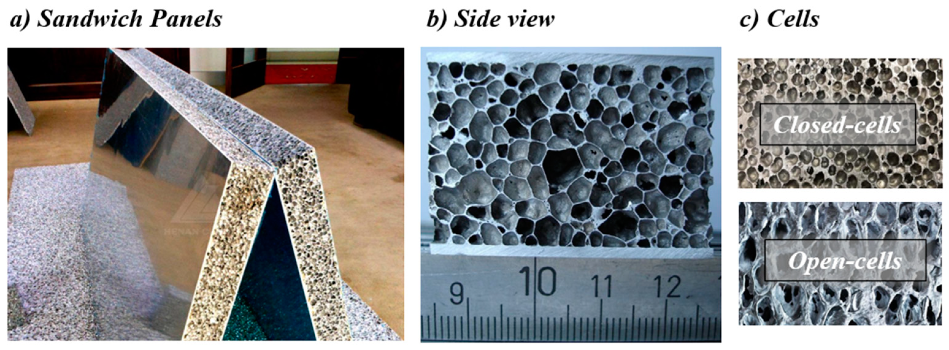
A further improvement of these systems consisted of using metal foams, which combine typical metal properties such as plasticity with an ultra-light structure and enhanced energy dissipation capacity. Metal foams are classified based on the production method and type of cellular structure that can be either open or closed. Open-cell metal foams have low stiffness, high porosity, and good thermal insulation [
8]. Conversely, closed-cell metal foams have a greater density, high compression/tension resistance, low heat conductivity, relatively high stiffness, and fire resistance [
9]. Compared with the original solid metals, foams provide several benefits: minimised weight-to-resistance ratio and higher bending stiffness and energy dissipation capacity. In addition, the main advantage that can be obtained from the use of metal foams is that there is no worsening of the mechanical characteristics following the lightening due to the introduction of the voids. Moreover, several ways to optimise the manufacturing process and composition of the foam cores exist, such as material selection, adhesive selection, improving foam homogeneity, and quality control (
i.e., visual inspections) to ensure consistent performance and structural integrity [
10,
11,
12]. Some applications of these technologies already exist and focus mainly on protective measures for defiance, railway engineering, ship construction, wind, and aeronautical engineering [
13,
14]. Nevertheless, currently, the use of metal foams in civil engineering is still limited or at an initial phase [
15,
16,
17,
18,
19,
20,
21].
Within this framework, this paper explores the constructional features, advantages, and potential applications of screwed steel–aluminium foam–steel (SSAFS) sandwich panels for application in floor decks of dry lightweight steel constructions [
22,
23,
24,
25]. This composite material comprises three layers: an outer layer of steel, a central layer of aluminium foam, and another outer layer of steel, as shown in
Figure 1. The steel layers are securely fastened to the aluminium foam core using screws, ensuring structural integrity and stability. Unlike other types of sandwich panels, such as those bonded with glues or adhesives, it is anticipated that sandwich panels connected with screws can effectively address the challenges associated with adhesive-based types, which often involve the loss of adhesion shortly after surpassing the steel’s yield strain. In addition to this, the SSAFS sandwich panels are expected to be characterised by: (1) High-strength and rigidity: steel contributes excellent tensile and compressive strength, while the aluminium foam core enhances the material’s stiffness-to-weight ratio. (2) Lightweight due to the low density of the aluminium foam, simplifying transportation and installation and reducing construction costs. (3) Sustainability: the aluminium foam is fully recyclable and environmentally friendly. This paper investigates the potentialities of high-performance SSAFS sandwich panels for application in the field of civil engineering. The research investigates the feasibility of the use of this technology for sandwich panels on spans typically found in the floor grids of steel buildings. The main objective of these tests is to show the potentialities and limitations of the use of self-drilling screws within SSAFS, making them suitable for lightweight structural systems. Therefore, prototype tests have been performed to assess the load-bearing capacity, bending, and shear resistances of different specimens. The results from the experimental tests revealed the potentialities of the use of SSAFS sandwich panels in terms of good strength-to-weight ratios, making them suitable for lightweight structural systems. However, their limitations are presented and discussed, defining the boundaries for their applications.
2. Experimental Tests on Base Materials
This section reviews an experimental campaign conducted on base materials (
i.e., aluminium foams only). The tests were performed at the StrEngTH (Structural Engineering Test Hall) laboratory of the University of Salerno. Samples of aluminium foams produced by the Canadian company Cymat Technologies Ltd. (Mississauga, ON, Canada) were tested to characterise their bending and shear resistance. For the sake of brevity, the results of two specimens for the bending test and two for the shear test are reported, but additional and detailed information is included in Latour
et al. [
18,
19]. Coupon tests were performed to characterise the material properties of the steel skins. Also, bearing tests were carried out to obtain the bearing resistance of the panels with screws. Once the individual materials were characterised, the sandwich panels were tested to investigate their overall mechanical behaviour, and the results are presented in
Section 3. The specimens were cut from panels of smart metal ML-0.51 and have dimensions of 650 mm × 150 mm × 25 mm, with a nominal density equal to 510 kg/m
3. The tested foams were produced according to a patented production process that starts from a metal matrix composite composed of aluminium alloy and ceramic particles. The specimens had a closed-cell structure with a variable cell size and a rather inhomogeneous cell size distribution. The voids were characterised by a stochastic distribution, with dimensions ranging from approx. 1 to 5 mm. The specimens were cut in water to avoid any thermal alteration of the base material. All tests were performed with a Schenck Hydropuls S56 (Silandro, Italy) universal testing machine consisting of a self-balanced steel frame used to counteract axial loads and a hydraulic piston with a load capacity of +/−630 kN and max stroke equal to +/−125 mm. The testing equipment is equipped with linear variable displacement transducers (LVDTs) to measure the axial displacements and a load cell to measure the tension/compressive loads. Furthermore, strain gauges were installed on the specimens to measure the longitudinal deformations accurately. Neoprene layers were placed between the cylinders and the panel, both at the force application point and at the supports, to guarantee total contact.
2.1. Tests on Aluminium Foam in Bending
For the three-point bending tests, two specimens with dimensions of 300 mm × 70 mm × 24 mm (C-3-25-F) and 299 mm × 75 mm × 24 mm (C-4-25-F) were obtained from the whole panel. The specimens were labelled with an ID code where the first letter and number individuate the coupon code, the second number individuates the panel thickness, and the last letter stands for the test type (
i.e., F indicates bending test). For both specimens, the tests were performed on a 225 mm span with displacement control, with a 1 mm/min speed rate.
Figure 2 shows the test set-up and instrumentations for the aluminium foams in bending.
The results of the bending test are depicted in
Figure 3a,b in terms of force–displacement response curves. Both specimens exhibited responses characterised by an initial elastic phase that ended just prior to the achievement of the failure load. The strain gauges allowed for calculating the material elastic modulus in bending, leading to values of
E = 8421 MPa,
σy = 7.53 MPa and
E = 6884 MPa,
σy = 7.18 MPa for the first and second tests, respectively.
The tests concluded with the foam samples breaking as expected, with failure due to the formation of a fracture located close to the force area. This type of failure mode was due to the concentration of maximum tensile stresses in the lower region, which initiated the vertical propagation of the crack. Successively, the specimens experienced a sudden drop in resistance.
2.2. Tests on Aluminium Foam in Shear
Two specimens with dimensions of 300 mm × 75 mm × 24.0 mm (C-1-25-T) and 300 mm × 68 mm × 24.4 mm (C-2-25-T) were obtained from a whole aluminium foam panel to carry out the shear tests. The specimens were labelled with an ID code where the first letter and number individuate the coupon code, the second number individuates the panel thickness, and the last letter stands for the test type (
i.e., T indicates shear test). The same instrumentation of the three-point bending tests was used. Laser meters were used to read the displacements at the centre and the supports. The test span remained unchanged (
i.e., 225 mm), but the load application point was brought closer to the left support until reaching 40 mm for the first test and 25 mm for the second test.
Figure 4 shows the test set-up and instrumentations for the aluminium foams in shear.
The results are shown in
Figure 5a,b in terms of shear–displacements. The first test did not lead to a shear failure, as it was affected by bending effects.
To overcome this issue, the force was applied at 25 mm from the support, leading to the desired shear failure pattern. The reduced distance enabled the specimen to experience shear failure, characterised as brittle, resulting in the simultaneous development of a fracture spanning the entire section. The experimental response was almost linear throughout this test. Therefore, the peak tangential stress at failure was estimated considering the elastic theory, leading to τmax = 3.75 MPa, considering a shear force at failure equal to 4.17 kN.
2.3. Bearing Tests
Preliminary bearing tests were carried out to characterise the bearing resistance of the sandwich panels joined by self-drilling screws. For this purpose, four specimens were produced: two of the through-screw type (
Figure 6a) and two of the non-through-screw type (
Figure 6b). Four specimens with dimensions of 155 mm × 75 mm × 25 mm were obtained from a whole aluminium foam panel. The through-screw panels were assembled with self-drilling screws of a length of 60 mm and a stem of 5 mm. Differently, the non-through-screw panels were assembled with self-drilling screws of 19 mm in length and a stem of 4.8 mm. The tensile tests with the through-screw panels were carried out by using two pieces of foam between which two steel sheets were placed. Conversely, for the tensile tests with the non-through-screw panels, a sample of foam was included in a grip made of steel sheets.
Figure 7 shows the test layout for the two panel typologies.
The results of the bearing tests are shown in
Figure 8 in terms of force–displacement curves for two tests belonging to the through-screw and non-through-screw panel typologies. The tests are not reported for the sake of brevity. However, it is worth mentioning that they show a consistent trend with the trend shown herein. From the comparison between the two typologies, it is observed that the trends of force–deformation curves are significantly different. A possible explanation for this scattering is due to the presence of inhomogeneities in the samples. For example, the presence of large pores close to the insertion point of the self-drilling screws caused failure during testing, thus affecting the whole trend of the force–deformation behaviour. The specimens with passing screws (
Figure 8a) showed the first signs of collapse when the foam bearing stress began to be overcome, with the consequent plasticisation of the contact surfaces with the screws and ovalisation of the holes, until the failure of one of the connectors. Conversely, the specimens with non-passing screws (
Figure 8b) collapsed when the cutting planes of at least one of the two sides failed. In other words, when the bearing stress of the foam was exceeded and the screws, rotating, began to plastically deform the contact surfaces with the aluminium foam until the complete extraction of the screws constituted the connection between the steel profile and the aluminium foam.
4. Comparison and Discussion
The panel connected with screws can effectively address the challenges associated with adhesive-based types, which often involve the loss of adhesion shortly after surpassing the steel’s yield strain. In this paper, for comparison purposes, some results from a previous experimental campaign [
18,
19] were reported to compare the overall behaviour of the sandwich panels equipped with two connection typologies: screwed and glued sandwich panels. The results were analysed and compared to assess the best choice in terms of the overall behaviour of the sandwich panel. In particular, three types of adhesives were compared: GeoLite Gel produced by Kerakoll (Sassuolo, Italy), SikaDur-30 by Huntsman (The Woodlands, TX, USA), and Araldite 2015 by Araldite (Mumbai, India), which is recognised as having some ductility that guarantees high adhesive performance.
By comparing the results of the SSAFS sandwich panels with glued panels (
Figure 13), it is observed that the panel glued with GeoLite Gel experienced increases in stiffness and strength, reaching a concentrated force of approximately 8 kN at the centre, even if it exhibited fragile behaviour due to the detachment of the skins from the core. In addition, GeoLite Gel showed less ductile behaviour and a sudden loss of resistance. Conversely, in the case of SikaDur, results showed a better response, reaching a force of 8.2 kN with satisfactory ductility with a maximum displacement of 20 mm. The panel glued with Araldite reached a test force of around 8 kN and showed very high ductility, with a maximum displacement of 28 mm, thus representing the best performance in terms of resistance and ductility among the glues. Overall, it can be summarised that within the range of the tested specimens, the adhesive has limited influence on the flexural strength and stiffness of the sandwich panels but significantly affects their ductility.
However, some additional considerations can be made. Although the panels joined together using glues and resins are easy and practical to apply, the choice of structural adhesives partly limits the ductility of the sandwich panel, and, therefore, the great dissipative capacity of the foams is not exploited. In addition, they have the disadvantage of degrading over time, losing their adhesion strength, and, if in contact with heat or aggressive agents, they lose their consistency and effectiveness. Furthermore, these glues have considerable cost, thus having a dominant influence on the final cost of the elements produced with their use.
5. Conclusions
Metal foams are innovative materials that have been engineered to possess appealing mechanical characteristics, including lightweight properties, a high strength-to-weight ratio, and effective insulation capabilities. Recently, the utilisation of these materials has shown promise in the creation of high-performance sandwich panels featuring steel exteriors and a core composed of metal foam. This development has the potential for diverse applications across multiple industries. Within this context, the primary objective of this study is to evaluate the performance of sandwich panels constructed from steel and aluminium foam joined by self-drilled screws, with the goal of serving as the basis for advancing a novel dry-assembled composite flooring system.
The results of the performed experimental tests demonstrate that the sandwich panels, composed of steel skins and aluminium foam cores, can be profitably used as primary structural elements in the field of civil engineering. However, the innovation of these elements is accompanied by some technical difficulties in implementation and assembly, which must be overcome before moving into practical applications. For this reason, a future objective could be a continuation of the experimental campaign to identify the most efficient detailing in terms of performance and economic efficiency. Concerning the panels joined by self-drilling screws, although sufficiently economical and considerable levels of resistance can be achieved, the installation is excessively laborious and prolonged, making their practical use in construction improbable and complex to be made. Furthermore, the overall weight of the numerous screws affects the final mass of the elements. However, it is worth highlighting that, thanks to the galvanic processes experienced by the screws during the production process, this method can guarantee efficient long-term behaviour in the presence of aggressive environments. It would be advisable to further evaluate connections of this type, such as rivets, to try to make the assembly process as simple and quick as possible. Other improvements can be made to optimise the performance of the panels.
In addition, although the panels joined together using glues and resins are easy and practical to apply, the choice of structural adhesives partly limits the ductility of the sandwich panel. Therefore, the potential dissipative capacity of the foams is not exploited. In addition, they have the disadvantage of degrading over time and losing their adhesion strength, and if in contact with heat or aggressive agents, they may lose their consistency and effectiveness. Possible solutions to overcome these issues may be the application of protective coatings against aggressive environments or adhesive maintenance and control over their expected lifespan. Furthermore, the commercial costs of some of these glues are considerably high, thus negatively influencing the final cost of the elements. A possible solution could be to cover the elements requiring use with insulating layers and paints. Finally, it is hoped that glues and resins can be released on the market at lower prices.


 ,
, 