Article

The Load-Bearing Capacity and Deformability of Connections of Wooden Elements with Composite Materials Based on Fiberglass

Institute of Industrial and Civil Engineering (IICE), National Research Moscow State Civil Engineering University, 26, Yaroslavskoye Shosse, Moscow 129337, Russia
*
Author to whom correspondence should be addressed.
Buildings 2023, 13(12), 3063; https://doi.org/10.3390/buildings13123063
Submission received: 18 October 2023 / Revised: 21 November 2023 / Accepted: 4 December 2023 / Published: 8 December 2023
(This article belongs to the Special Issue Safety and Optimization of Building Structures)

Abstract

:
The research focuses on connections of wooden structural elements with composite materials based on fiberglass. An overview of existing research and regulatory technical documents in the field of connections between wooden elements and composite materials based on fiberglass has been conducted. A type of connection for wooden elements with composite materials based on fiberglass is proposed. The article presents the results of strength and deformability studies of the developed connection. Strength characteristics are established in the form of the slice resistance of the composite material along the welding seam in the connection, a tear resistance of the composite material from the base, and the chipping of the composite material. The deformability characteristics of fiberglass connections under short-term machine testing with linearly increasing load in samples have been determined.

1. Introduction

Construction is a major consumer of business wood. Wood is a natural polymer and a building material with unique properties that provide effective use for wooden structures in load-bearing and enclosing parts of buildings and structures. The conservation of forest resources requires the rational use of wood in the manufacture of new wooden structures. The existing dimensions of natural forest materials do not allow for the solving of tasks in developing wooden structures without using connections for joining, bonding, and reinforcing individual wooden elements.
The relevance of this work is the need for the development and effective research connections of wooden elements using modern composite materials based on fiberglass for structures made of wood and plastics, to obtain reliable data for their calculation and construction.
The use of modern composite polymer materials with known properties makes such a technical task practically solvable with the lowest economic costs. New high-strength materials—composite materials—without compromising the appearance and dimensions of the wooden structure significantly increase its service life and reliability [1].
In [2], the mechanical properties of wooden structures crossed and reinforced with basalt fiber are determined. Samples in the form of cellular frames with and without reinforcement are tested in the laboratory. The article concludes with regard to the possibility of a joint use of composite materials and wooden structures for the construction of buildings and structures.
Increasing the load-bearing capacity of glued wooden structures is possible via reinforcement with polymer rods or grids. This problem was studied in [3], whose purpose was to determine the elastic modulus of glued wood during bending, taking into account the reinforcing layer.
In [4], extensive studies have been carried out, showing the potential and possibilities of the transverse reinforcement of wooden elements in areas of expected destruction. Fiberglass is embedded in polyurethane glue when gluing lamellas made of spruce wood. The glue connects the wooden slats to each other and serves as a matrix for fiberglass. By adding a small amount of high-strength fibers, structural wood can be turned into a mechanically more resilient composite material capable of withstanding all types of loads.
The results of studies by H.J. Blab and M. Romani show that bending stiffness and bearing capacity can be increased by reinforcing glued beams with fiberglass lamellas in the stretched zone of cross-sections [5,6]. When strengthening the stretched zone of the flexural beam, an increase in bearing capacity via the strength criterion is more pronounced than via deflections when working for bending. Bending calculations based on the theory of composites showed good convergence with the values obtained during the tests. The increase in both bearing capacity and bending stiffness depends on the number of reinforcement in the general cross-section, the properties of the material properties of the fiberglass plates and wood, as well as the position of fiberglass plates in the cross-section.
In [7], a method for strengthening the support zones of beams with a polymer composite based on fiberglass and an epoxy matrix with the inclusion of carbon nanotubes in its composition was investigated.
The problem of prestressing glued wooden structures was considered in the dissertation work [8], which investigated the question of the possibility of strengthening glued beams with prestressed polymers reinforced with basalt fiber.
The issues of restoring damaged wooden structures using various materials were studied [9]. Samples with different configurations of reinforcing layer placements and their types were selected for testing. The results of tests on laminated wooden beams reinforced with fiberglass reinforcement are presented.
In [10], work was conducted to reinforce the wooden load-bearing structures of the Mansfeld Palace in Germany. The use of wood–polymer–concrete composite structures was an effective solution to increase the load-bearing capacity and rigidity of wooden beams working on bending. The results of bending tests on a short-term load confirmed the effectiveness of simultaneously reinforcing the stretched zone of beams with composite materials and the compressed zone of beams with polymer concrete without significantly increasing the cross-section height of wooden elements. The load-bearing capacity of wooden structures increased by 86% compared to the variant without reinforcement.
In the work of engineers Geshanov I. and Kachlakev D., the process of strengthening floor beams in a golf club building in Sofia, Bulgaria, [11] was considered. The work was carried out during the reconstruction of the facility due to the weakening of the structures and the need to increase the load on the floor. Strengthening was achieved by gluing unidirectional carbon tapes in the stretched zone of the beams and installing transverse clamps along the length of the structure. The load-bearing capacity of the overlap elements has been increased by 27%, and the deformability has been reduced by 20%.
In Italy, in 2005, the CNR-DT 201/2005 manual was issued on the design and installation of systems with an external strengthening of existing wooden structures with polymer composites. These guidelines provide recommendations on the use of composite materials, the preliminary assessment of the condition of the structure, and the feasibility of using composites [12]. The manual includes general provisions for design, requirements for wood, composites, and adhesives. The document also includes examples of successfully completed projects involving the strengthening of load-bearing wooden structures in buildings and cultural heritage sites in Italy.
The work of Steffen Franke, Bettina Franke, and Annette M. Hart describes the process of repairing the support zones of beam structures in Klein Castle in the UK [13] by installing a wooden prosthesis on glued composite lamellae and composite reinforcement.
Engineers from the Russian company NII VSTU “InterTEC” [14] developed a carbon fiber reinforcement project (ITECWRAP/ITECRESIN composite material based on high-strength carbon fibers) for wooden coating beams damaged as a result of a violation of the storing conditions and storing glued wooden structures.
In the work [15], the issue of the influence of humidity on the adhesion of the interface between wood and the composite material was studied. To investigate the effect of moisture in the operating mode on fracture patterns and mechanical properties of the “carbon fiber–wood” connection, experimental studies and modeling were conducted. Experimental research revealed the failure patterns of the carbon fiber–wood connection samples under different moisture levels of the wooden elements. The destructive load of wood element samples reinforced with carbon fiber decreases as the duration of the exposure of samples in a humid environment increases. In conditioned samples, an increase in moisture leads to a weakening of the bond between the epoxy adhesive and wood. The adhesion energy between cellulose and epoxy resin was measured under both dry and wet conditions. It was observed that water molecules diffuse into the bond, resulting in a significant reduction in adhesion energy. The adhesion energy in wet conditions decreases to one-third of the adhesion energy in dry conditions. The test results indicate that the bond strength between the epoxy adhesive and wood decreases with increasing moisture during sample conditioning, and the mechanical properties of wood reinforced with carbon fiber composite are significantly reduced. This study demonstrates the impact of moisture on the properties of wood bonded with carbon fiber and elucidates the molecular mechanism that governs the structural behavior of bilayer materials in the presence of water. The combination of macro-scale experimentation and nano-scale modeling illustrates an approach that can also be applied to other composite material systems. Additionally, it is essential to consider micro-scale mechanisms to bridge the scale transition and facilitate a comprehensive understanding of the studied process and material.
In the work [16], the influence of temperature on the adhesion between wood and composite material was studied. To investigate the impact of temperature on the interfacial behavior of the carbon fiber plastic–wood composite, experimental studies and modeling were conducted. Experimental results demonstrate that the interfacial connection between carbon fiber and wood, which is strong at low temperatures, deteriorates as the temperature increases. The fracture energy of the carbon fiber–wood system based on epoxy adhesive and wood is measured through shear modeling, which is in good agreement with the results of experimental observations. The simulation results demonstrate that the deterioration of the constituent materials is more serious at high temperature, which is the fundamental mechanism of temperature influence on the interfacial behavior of the entire system of materials. This study highlights the influence of temperature on the macroscopic properties of the wood–carbon fiber system and elucidates the molecular mechanism that alters the structural behavior of the constituent materials at different temperature levels.
In addition to scientific sources, the following regulatory and technical documents [17,18,19] are considered: Eurocode 5: Design of timber structures—Part 1-1: General—Common rules and rules for buildings; Eurocode 5: Design of timber structures—Part 1-2: General—Structural fire design; Eurocode 5: Design of timber structures—Part 2: Bridges, DIN EN 408-2012 “Timber structures—Structural timber and glued laminated timber—Determination of some physical and mechanical properties” (Germany), [20] ACI 440R-96 State-of-the-Art Report on Fiber-Reinforced Plastic (FRP) Reinforcement for Concrete Structures, Reported by ACI Committee, Russian standards.
The considered scientific and regulatory sources allow us to conclude that it is necessary to use effective joints of wooden structures created on the basis of modern composite materials, the physical and mechanical properties of which best correspond to the properties of a natural anisotropic polymer-structured wood.
The study objective of this article is the deformability of a symmetrical double-shear connection. The subject of the study is the load-bearing capacity of the proposed connection using composite materials.
The scientific novelty consists of experimental data and methods for assessing load-bearing capacity and the choice of rational parameters for connections of wooden structures based on composites.
The recommended ratio between the width of the glued surfaces of the wooden elements and the thickness of the composite material needs to be recognized. The minimum thickness layer of composite material in the working joint should also be determined.

2. Materials and Methods

The purpose of the tests is to obtain experimental data to determine the strength and deformation characteristics [21] of fiberglass connections of wooden elements on samples to calculate these type of connections when developing wooden elements of a composite section and when reinforcing existing wooden structures.
The strength and deformability of the joints of wooden elements determine the work of structures under load. To determine the main characteristics of the joints—the maximum bearing capacity of the joint (breaking force) Nmax, the upper boundary of the elastic work area of the NI-II joint, deformations of the joint at characteristic loading levels—tests were carried out on samples of the studied joints of wooden elements using a composite material based on fiberglass.
Samples for testing this type of compounds are symmetrical, double-shear, and intended for testing using a compressed circuit.
In this work, we consider one variant of the type of connection of wooden elements with a composite material (fiberglass) layer-by-layer formation directly on a wooden structure and three types of composite material.
The connection of wooden elements in fiberglass through external gluing with a composite material is formed during the manufacturing process on the open-side surfaces of the joined elements. Based on three types of composite material, these compounds were considered each of which had three options for gluing thickness: 2 layers—0.6 mm; 4 layers—1.1 mm; 6 layers—1.6 mm.
Figure 1 shows a general view of the joint of wooden elements with a composite material based on an epoxy matrix and fiberglass, with the side surfaces of the joined elements externally glued.
Three types of composite materials are considered for use in wooden structures of this type of compound:
Type 1—The joint of wooden elements with a composite material based on KDA m epoxy resin with an Etal-45 hardener (matrix) and a reinforcing component in the form of T13 fiberglass (designation of the composition of the composite material KDA + T13).
Type 2—The joint of wooden elements with a composite material based on PolyTay 303TAE polyester resin with Butanox M50 hardener (matrix) and a reinforcing component in the form of T13 glass fiber (designation of the composition of the composite material PR + T13).
Type 3—The joint of wooden elements with a composite material based on KDA m epoxy resin with an Etal-45 hardener (matrix) and reinforcing components in the form of RF fiberglass (designation of the composition of the composite material KDA + RF).
Each type of joint was studied at a composite material thickness of 2 layers (series 1), 4 layers (series 2), and 6 layers (series 3). For each thickness of the fiberglass of each type of composite material, 3 samples were tested, wherein each series included 9 samples—a total of 27 samples of this compound for 3 types and three standard sizes of composite material thickness. Each type of connection is made in the form of symmetrical double-cut samples of the same size with double-sided fiberglass.
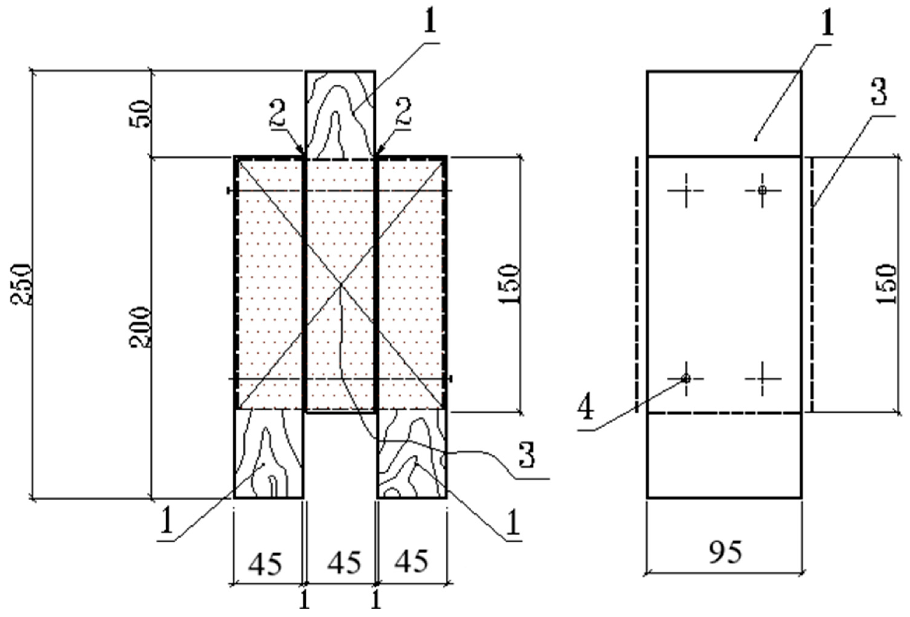
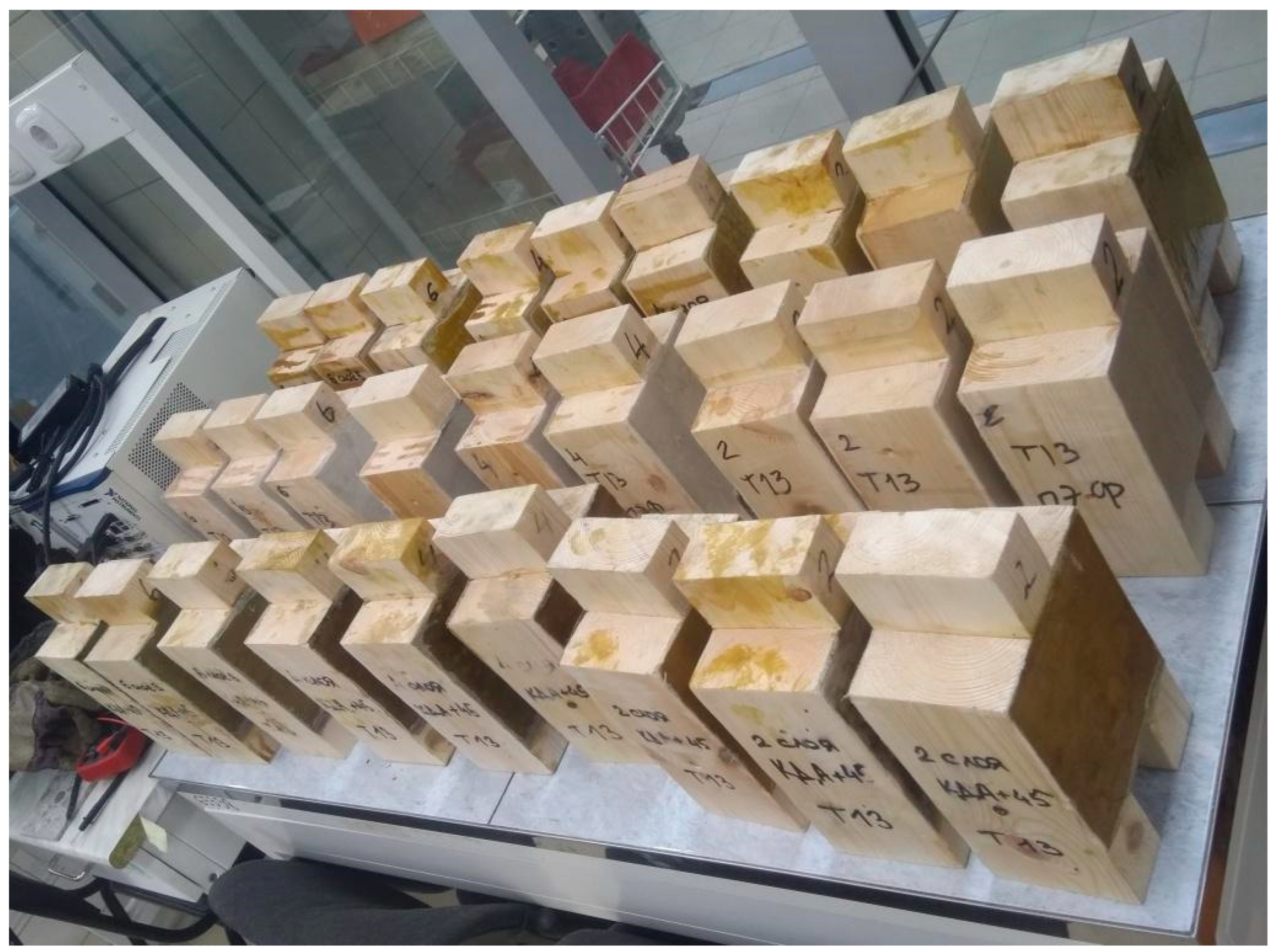
Figure 2 shows the design of the connection samples, taking into account the actual dimensions of the wooden elements. The general view of the manufactured samples is shown in Figure 3.
Wooden elements of fiberglass connections are made from pine and spruce wood of the 1st and 2nd grade. The quality of the wood, its strength, and its dimensions of wooden elements made of softwood lumber used in load-bearing wooden structures on fiberglass connections must meet the requirements of Russian standards.
The humidity of wood elements intended for applying composite material should be 12 ± 3%. All test series were in fact performed at a constant temperature of 20 °C, with moisture content in wood in the order of 18%, which has major effects on the mechanical properties of materials and connections.
The composite material is formed directly on the structure or on individual elements based on an epoxy or polyester matrix reinforced with T13 fiberglass. The composition of polymer matrices based on epoxy resins and polyester resin is presented in Table 1.
T-13 fiberglass fabric, in accordance with GOST 19170-2001, was used as a reinforcing component T-13 fiberglass of plain weave, for which the thread is produced from aluminoborosilicate glass type “E”, with a fabric thickness of 0.27 ± 0.04 mm.
The composite material is obtained simultaneously with installation joints, through a process of layer-by-layer external lining on the side surfaces, where several layers of fiberglass are impregnated with an epoxy or polyester binder. As a result of polymerization of the binder composite material, the wood of the joined elements is formed simultaneously with the formation of adhesive bonds at the fiberglass–wood boundary.
The installation of connections between wooden elements of this type of joint includes the following stages of work: preparing the surface of wooden elements for application of composite material; preparing the required amount of fiberglass fabric impregnated with a binder; applying a primer layer based on a polymer matrix to the contact surfaces of wooden elements; and applying the designed number of layers of fiberglass impregnated with a binder to the contact surfaces of wooden elements.
Preparing the surface of workpieces for the application of a composite material includes cleaning from dust and dirt, removing weak surface areas to a solid base of the material, and treating with swabs soaked in acetone.
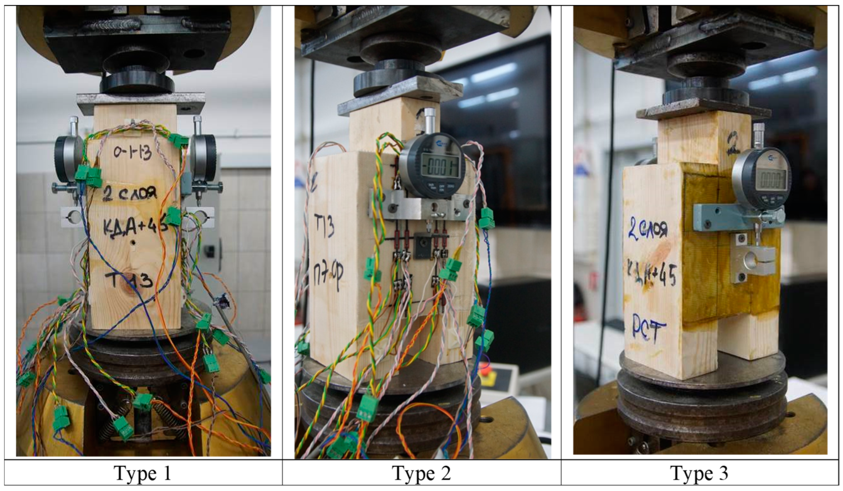
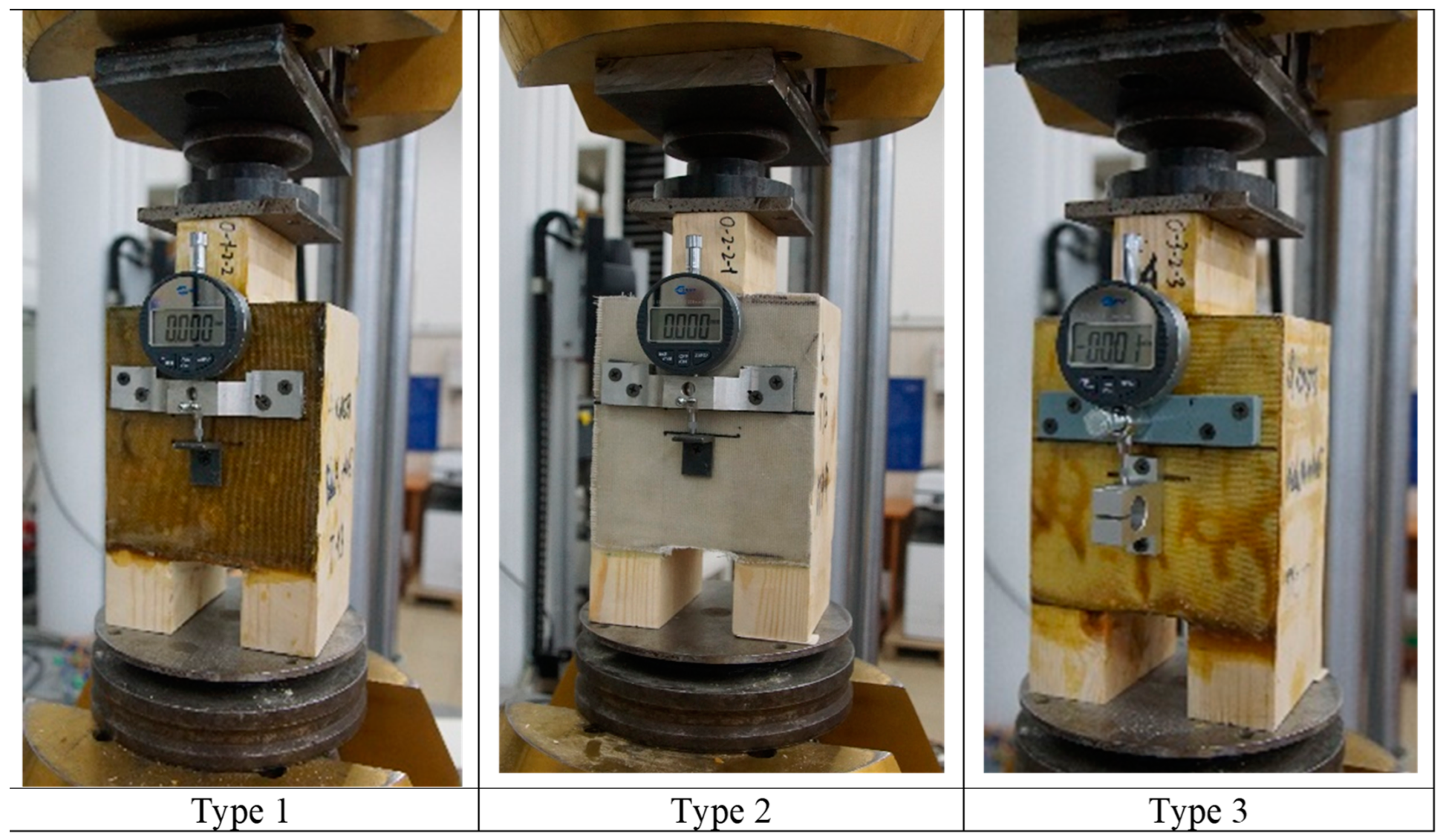
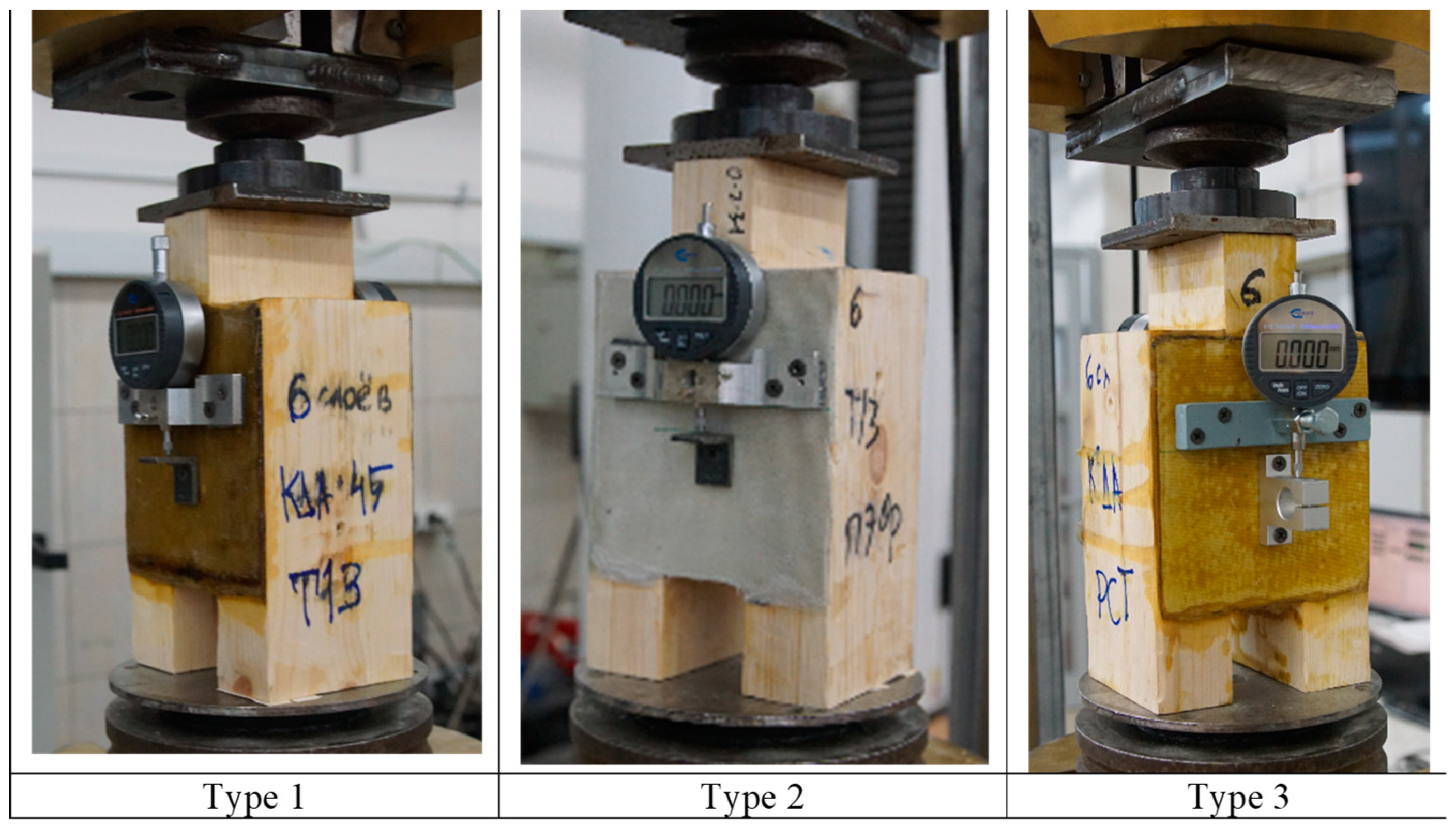
Lists of samples of this type of compound, indicating the marking of the samples, the composition of the composite material, and the number of layers of the composite material, are presented in Table 2, Table 3 and Table 4. The general view of the samples during testing is presented in Figure 4, Figure 5 and Figure 6.
The tests were carried out according to a compressed scheme [22]. The load was applied to the middle element of the sample through a spherical bearing. The load was applied at a constant speed. The load step was 1 kN. After each loading step, the sample was unloaded to a conditional zero.

3. Results

The work of the first series of samples at the stage preceding destruction was accompanied by an intensive increase in deformations compared to all previous loading levels. At the same time, instantaneous and brittle destruction, characteristic of joints of wooden elements with the use of glue, was not observed during tests of the double layer of all types of this compound. The test results for the first series of specimens are presented in Table 5.
The failure occurred as a result of the combined action of two factors: the disruption of adhesive bonds between the composite material and the side surface of the bonded wooden elements, resulting in a gradual separation of the composite material from the substrate, and the shearing of the composite material along the seams of the specimen. There was no failure of the wooden elements within the specimens during the failure of these compounds.
The destruction of the second series of samples occurred as a result of the manifestation of two factors: a violation of the adhesive bonds between the composite material and the side surface of the wooden elements being joined, which manifested itself in the separation of the composite material without its destruction from the base, as well as the destruction of the connection “on wood” as a result of chipping wood along the fibers in separate sections of the composite material. The test results of the second series of samples are presented in Table 6.
According to the instructions given in [23,24,25], all types of the fiberglass compounds belong to the compounds of the first group based on the nature of work—with a linear dependence of the difference in total deformations ∆Dp on the force within the elastic work of the joint. The level of loading was taken as the destructive force, at which the sample was not capable of perceiving a further increase in load. The destructive load was recorded by stopping or dropping the readings of the force meter with a continuous increase in deformations of the sample.
The destruction of the third series of samples occurred as a result of the manifestation of two factors: a violation of the adhesive bonds between the composite material and the side surface of the wooden elements being joined, which manifested itself in the separation of the composite material without its destruction from the base, as well as the destruction of the connection “on wood” as a result of chipping wood along the fibers in separate sections of the composite material. The test results of the third series of samples are presented in Table 7.
The evaluation of the load-bearing capacity and deformability of the connections based on the test results was conducted following the methodology described in [23,25]. From the tests, the following strength and deformation characteristics of the connection specimens were determined: destructive load Nmax, (kN); full Dp deformations (mm), residual Dp (mm), elastic Dp (mm), and difference to complete deformations ∆Dp (mm) of joint samples at each loading stage; according to the graph “N-∆Dp”, the load NI-II, (kN), corresponding to the upper boundary of the elastic region of the joint samples, was determined; and the load Nd (kN), corresponding to the calculated bearing capacity of the joint. According to the total duration of the test t1 (sec), the so-called required reliability coefficient γν for the value of the destructive force Nmax was determined. Since the destruction of the samples of all types of this compound bore signs of brittle fracture, a reliability coefficient required for brittle fracture was adopted for the assessment of the bearing capacity of the connections (use only Latin letters in all characters):
γν = 1.64 × (1.94 − 0.116 × lg t)
where t = tmax/38.2 is the time given to the constant action of the Nt force on the sample. Then, using the TSNIISK technique [23,25], two values were obtained from the experiment characterizing the calculated bearing capacity Np = Rexp of the compound sample:
  • By a destructive force:
Rexp·v ≤ Nmax/γν
  • At a force corresponding to the upper boundary of the area of elastic joint operation:
Rexp·I-II ≤ NI-II/1.3
From the two obtained values, the minimum value was taken as the calculated bearing capacity of the connection sample: Np = min {Rexp·v, Rexp·I-II}.
For a comparative assessment of the deformability of connections, complete deformations DpNp (mm) of samples at intermediate load levels corresponding to the calculated bearing capacity Np of the connection samples were determined through interpolation. Complete deformations DpI-II were also determined under the load NI-II. Additionally, the rate of deformation growth within the calculated bearing capacity of the connections, DpNp/Np, and within the upper limit of the elastic work region of the connection was calculated—DпI-II/NI-II (mm/kN).
The shear resistance of this type of compound was evaluated according to three criteria of the stress–strain state during the operation of the joints under load:
  • By the area of the cut of the composite material along the length of the seam as linear shear resistance.
  • As the linear bearing capacity of the joint—by 1 cm (mm) of the seam length:
    TFGC = Np/(navg × Lseam),
    where Np is the force corresponding to the calculated bearing capacity of the sample (kN (N)); navg is the resistance of the joint to the shear force on the separation of the composite material from the base:
    RsepFGC = Np/[npl × (Lseam × b)],
    where npl = 2 is the number of separation planes.
  • As the resistance of the joint to shear force along shear:
    RavgFGC = Np/[navg ∗ (Lseam ∗ tFGC)],
    where (Lseam ∗ tFGC) is the working cross-sectional area per 1 slice in the sample; b is the width of the wooden element.
A summary of the test results of the samples of all types of the fiberglass compounds are presented in Table 8.
From the consideration of Table 8, we see that with an increase in the thickness of the composite material, there is a decrease in the shear strength of the fiberglass compound according to the criterion of the shear strength of the composite material and an increase in the shear strength of this compound type according to the criteria of the linear bearing capacity of the joint per unit length of the joint and by the separation of the composite material from the surface of the joined wooden elements. This can be explained by the fact that the failure of these connections exhibits a mixed nature, and the predominance of one factor over the other depends on the thickness of the composite material. It is obvious that an increase in the thickness and, accordingly, the bearing capacity “on the shear” of the composite material leads to a complication in the nature of the work and the nature of the destruction of the joint when the destruction of the adhesive bonds between the composite material and the contact surface of the connected wooden elements manifests itself earlier than the destruction of the composite material of the pasting.
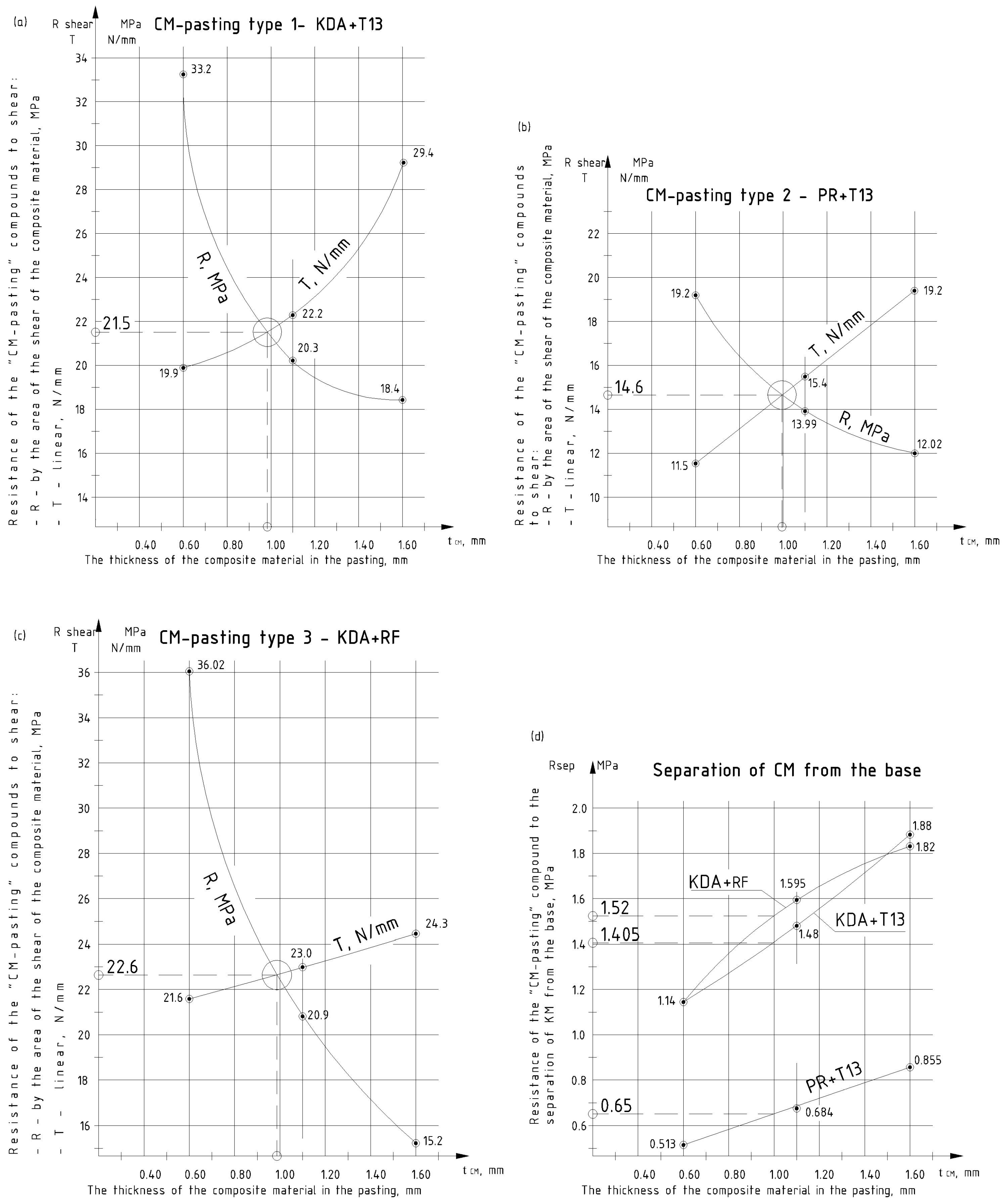
The dependences of the bearing capacity of these compounds on the thickness of the composite material on the samples of the first, second, and third type of compounds are shown in the graphs in Figure 7.
From Figure 7, we can see that the effective thickness of the composite material for all types of this compound is tFGC ≈ 1 mm, which, according to the test results of the compound samples, corresponds to:
The design of the shear resistance of the composite material for type 1 joints RavgFGC1 = 21.5 MPa, for type 2 joints RavgFGC2 = 14.6 MPa, and for type 3 joints RavgFGC3 = 22.6 MPa.
The calculated resistance toward the separation of the composite material from the base for type 1 joints RavgFGC1 = 1.4 MPa, for type 2 joints RavgFGC2 = 0.65 MPa, and for type 3 joints RavgFGC3 = 1.5 MPa.
With an increase in the thickness of the composite material, the nature of the destruction of the samples changes, and in the work of the fiberglass compound, a cut of the composite material not only begins to appear, but also a detachment of the overlay from the surface of the joined wooden elements. In this case, the bearing capacity of the joint depends on the width of the gluing pads on the wooden elements to be joined, which in the tested samples is bpasting = 45 mm. With the effective thickness of the composite material in this type of compound tFGC = 1 mm, we obtain the ratio between the width of the surfaces to be glued bpasting of wooden elements and the thickness of the composite material tFGC/bpasting = 1/45. For this type of compound, we accept that the ratio between the width of the glued surfaces bpasting of the wooden elements and the required thickness of the composite material tFGC = 1/45 bpasting.
The fiberglass connections type 1 and type 3, made on the basis of KDA m epoxy resin with Etal-45 hardener, which reinforce components in the form of fiberglass T13 (type 1) and rolled fiberglass RF (type 3), have similar strength and deformation characteristics, which we propose to combine.

4. Discussion

In this work, we consider a method for connecting wooden elements with composite materials based on fiberglass. For each type of connection, strength characteristics were determined depending on the stress state and depending on the type of composite material used in the connection, as well as deformation characteristics that determine the deformability within the limits of the calculated bearing capacity and elastic operation of the connections.
The main standardized characteristics of the strength of this type of compound are the calculated resistance of the joints, which is determined based on an assessment of the bearing capacity of the joints according to the method used in [23,25], based on the test results of the calculated bearing capacity of the samples.
For this type of compound, strength and deformation characteristics that correspond to the calculated load-bearing capacity of the connections have been established:
  • The design in shear resistance of the composite material:
    For fiberglass connections type 1 (KDA-M + T13) and type 3 (KDA-M + RF):
    RshFGC = 20 MPa.
    For fiberglass connections type 2 (PR + T13):
    RshFGC = 14 MPa.
  • The calculated resistance to the separation of the composite material from the base:
    For connections type 1 (KDA-M + T13) and type 3 (KDA-M + RF):
    • For composite material thickness up to 1 mm Rsep·FGC = 0.9 MPa;
    • For composite material thickness from 1 mm to 1.6 mm Rsep·FGC = 1.0 MPa;
    • For composite material thickness more than 1.6 mm Rsep·FGC = 1.1 MPa.
    For connections type 2 (PR + T13):
    • For composite material thickness up to 1 mm Rsep·FGC = 0.5 MPa;
    • For composite material thickness from 1 mm to 1.6 mm Rsep·FGC = 0.68 MPa;
    • For composite material thickness more than 1.6 mm Rsep·FGC = 0.85 MPa.
  • The deformability of connections at the level of calculated load-bearing capacity:
    For connections type 1 and type 3 Dp/Nd = 0.0021 mm/kN;
    For connections type 2 Dp/Nd = 0.0031 mm/ kN.
Based on the tests carried out and the processing of experimental results, the calculated resistances of this type of compound to the main types of stress state for which the connection operates when receiving a shear force were established, including the calculated resistance to the shearing of the composite material along the edge joint and the separation of the composite material from the surface of the wooden element.
The design of the shear resistance of composite material RshFGC:
For this type of compound, based on an epoxy matrix and T13 fiberglass or RF fiberglass RshFGC = 20 MPa;
For this type of compound, based on a polyester matrix and T13 fiberglass RshFGC = 14 MPa.
The calculated resistance to the separation of the composite material from the wooden element Rsep·CM is presented in Table 9.
The calculated load-bearing capacity of this type of compound should be determined for the shear of the composite material along the edge joint and for the separation of the composite material from the surface of wooden elements according to the following formulas:
(a)
From the shearing conditions of the composite material:
[Tshear FGC] = RshearFGC × LFGC × tFGC × nsh,
where RshearFGC = RshFGC/(γm ∗ γmn) is the calculated resistance of fiberglass connection; RshCM is the design shear resistance of the composite material; γm = 1.2 is the reliability coefficient for a composite material in this type of compound; γmn = 1.4 is the reliability coefficient by the method of manufacturing a joint for the manual molding of a composite material and a cold-curing epoxy matrix under construction site conditions, where γmn = 1.1 in conditions of organized production; LFGC = LO −2 × 50 is the estimated length of this compound; tFGC is the thickness of this compound; and nsh is the number of calculated shears of this type of compound in the calculated area.
The estimated length of this compound should be taken as 2 × 50 mm less than the actual length of the pasting LO at the estimated seam: LFGC = LO −2 × 50 mm site and damage to the wooden structure. When developing a new wooden element of a composite section, the length of this compound LO should be set to at least 1/4 of the span of the element being created.
The thickness of the composite material tFGC in this type of compound should be specified at least:
tFGC = 0.025 × h1 × (hmin/h1) [mm],
where h1 is the width of the pasted surface of one branch of a composite wooden element, (mm); hmin is the smallest cross-sectional height of one branch of a composite timber element (mm).
(b)
From the condition of separation of the composite material from the surface of wooden elements:
[TSEP FGC] = RSEP × LFGC × h1 × npl,
where RSEP = RsepFGC/(γm ∗ γmn) is the calculated resistance of the fiberglass joint to the separation from the surface of the wooden element; RsepFGC—see point 8.62; and npl − npl = 2 is the number of planes separation of the fiberglass from the wooden element in the design area. The estimated length of this compound should be taken as 2 × 50 mm less than the actual length of the pasting LO at the estimated seam.
The data obtained make it possible to use a pliable symmetrical double-shear connection, traditional for joints with mechanical connections, as a rigid adhesive type of connection [23,24,25,26].

5. Conclusions

On the basis of the methodology for assessing the load-bearing capacity of joints of wooden structures [23,25] and the processing of the test results of samples, strength characteristics corresponding to the calculated load-bearing capacity of this type of compound were established:
  • Calculated shear resistance of composite material for type 1 joints (KDA-M + T13) and type 3 (KDA-M + RF) RavgFGC = 20 MPa.
  • Calculated shear resistance of composite material for type 2 joints (PR + T13) RavgFGC = 14 MPa.
  • Calculated resistance to the separation of composite material from the base for type 1 joints (KDA-M + T13) and type 3 (KDA-M + RF):
    For composite material thickness up to 1 mm Rsep·FGC = 0.9 MPa;
    For composite material thickness from 1 mm to 1.6 mm Rsep·FGC = 1.0 MPa;
    For composite material thickness greater than 1.6 mm Rsep·FGC = 1.1 MPa.
  • Calculated resistance to the separation of the composite material from the base for type 2 joints (PR + T13):
    For composite material thickness up to 1 mm Rsep·FGC = 0.5 MPa;
    For composite material thickness from 1 mm to 1.6 mm Rsep·FGC = 0.68 MPa;
    For composite material thickness greater than 1.6 mm Rsep·FGC = 0.85 MPa.
  • Total deformations at the level of the calculated load-bearing capacity of this type of compound were Dp = 0.024−0.038 mm, which corresponds to the intensity of deformation growth on average Dp/Nd = 0.0019−0.0023 mm/kN for type 1 and type 3 joints, and 0.0031 for type 2 joints.
  • The recommended ratio between the width of the glued surfaces of the wooden elements and the thickness of the composite material tFGC = 1/45 bpasting has been determined.
  • To ensure the operation of this type of compound from the cut-off condition of the composite material, the minimum thickness layer in the working joint should be at least tFGC = 1 mm.
  • Similar studies need to be carried out on samples using linear and beam models.

Author Contributions

Conceptualization, A.T.; methodology, A.T.; software, L.N. and K.A.; validation, L.N. and K.A.; formal analysis, A.T.; investigation, A.T., L.N. and K.A.; resources, A.T. and L.N.; data curation K.A.; writing—original draft preparation, L.N. and K.A.; writing—review and editing, A.T.; visualization, L.N.; supervision, A.T.; project administration, A.T.; funding acquisition, A.T. All authors have read and agreed to the published version of the manuscript.

Funding

This research is funded by the grant issued by the National Research Moscow State University of Civil Engineering as a result of a competition among the lecturers for the implementation of fundamental and applied scientific research (R&D) by the teams of NRU MGSU researchers (Order 453/130-15/05/2023-project No. 15).

Data Availability Statement

The data presented in this study are available on request from the corresponding author. The data are not publicly available due to privacy.

Conflicts of Interest

The authors declare no conflict of interest.

References

  1. Rutman, U.L.; Meleshko, V.A. The generalization of the flexibility method for elastoplastic computation of rod systems. Mater. Phys. Mech. 2017, 31, 67–70. [Google Scholar]
  2. Kozinetc, K.G.; Kärki, T.; Barabanshchikov, Y.G.; Lahtela, V.; Zotov, D.K. Mechanical properties of sustainable wooden structures reinforced with Basalt Fiber Reinforced Polymer. Mag. Civ. Eng. 2020, 100. [Google Scholar] [CrossRef]
  3. Togay, A.; Döngel, N.; Söğütlü, C.; Ergin, E.; Uzel, M.; Güneş, S. Determination of the Modulus of Elasticity of Wooden Construction Elements Reinforced with Fiberglass Wire Mesh and Aluminum Wire Mesh. BioResources 2017, 12, 2466–2478. [Google Scholar] [CrossRef]
  4. Trummer, A.; Wilhelm, F. Zuschnitt 17. Holz + Proholz. Austria 2005, 11, 24. [Google Scholar]
  5. Blaß, H.; Romani, M. Biegezugverstärkung von Brettschichtholz mit CFK- und AFK-Lamellen. Bautechnik 2002, 79, 216–224. [Google Scholar]
  6. Blaß, H.; Romani, M. Tragfähigkeitsuntersuchungen an Verbundträgern aus BS-Holz und Faserverbundkunststoff-Lamellen. Eur. J. Wood Wood Prod. 2001, 59, 364–373. [Google Scholar]
  7. Lisyatnikov, M.S.; Glebova, T.O.; Ageev, S.P.; Ivaniuk, A.M. Strength of Wood Reinforced with a Polymer Composite for Crumpling across the Fibers. IOP Conf. Ser. Mater. Sci. Eng. 2020, 896, 012062. Available online: https://iopscience.iop.org/article/10.1088/1757-899X/896/1/012062/pdf (accessed on 17 October 2023). [CrossRef]
  8. Zachary, C.; Kavan, S. Feasibility of Strengthening Glulam Beams with Prestressed Basalt Fibre Reinforced Polymers; Department of Civil and Environmental Engineering, Division of Structural Engineering Steel and Timber Structures, Chalmers University of Technology: Göteborg Sweden, 2012. [Google Scholar]
  9. Stoyanov, V.O. Strength and Deformability of Bent Wooden Elements Reinforced with Polymer Composites. Master’s Thesis, TSNIISK Named after V.A. Kucherenko—M, Moscow, Russia, 2018. (In Russian). [Google Scholar]
  10. Kay-Uwe, S. Hochleistungskunststoffe für die Tragwerksverstärkung von Holzkonstruktionen im Bestand. Z. Nachhalt. Bau. Bauwerkserhaltung Denkmalpfl. Sonderdr. Bausubstanz 2010, 4, 38–43. [Google Scholar]
  11. Geshanov, I.; Kachlakev, D. Composite reinforce concrete-timber floor system externally strengthened with CFRP composite. In Proceedings of the 13th International Conference SFR, Edinburgh, UK, 6–9 September 2010; pp. 151–153. [Google Scholar]
  12. CNR-DT 201 Advisory Committee on Technical Recommendations for Construction. Italy. 2005, p. 58. Available online: https://www.cnr.it/en/node/2637 (accessed on 17 October 2023).
  13. Steffen, F.; Franke, B.; Harte, A.M. State of the Art. Constr. Build. Mater. 2015, 97, 2–14. [Google Scholar] [CrossRef] [PubMed]
  14. Zhou, A.; Tam, L.; Zechuan, Y.; Lau, D. Effect of moisture on the mechanical properties of CFRP–wood composite: An experimental and atomistic investigation. Compos. Part B 2015, 71, 63–73. [Google Scholar] [CrossRef]
  15. Tam, L.; Zhou, A.; Yu, Z.; Qiu, Q.; Lau, D. Understanding the effect of temperature on the interfacial behavior of CFRP-wood composite via molecular dynamics simulations. Compos. Part B 2017, 109, 227–237. [Google Scholar] [CrossRef]
  16. Eurocode 5: Design of Timber Structures—Part 1-1: General—Common Rules and Rules for Buildings. Available online: https://www.phd.eng.br/wp-content/uploads/2015/12/en.1995.1.1.2004.pdf (accessed on 17 October 2023).
  17. Eurocode 5: Design of Timber Structures—Part 1-2: General—Structural Fire Design. Available online: https://www.phd.eng.br/wp-content/uploads/2015/12/en.1995.1.2.2004.pdf (accessed on 17 October 2023).
  18. Eurocode 5: Design of Timber Structures—Part 2: Bridges. Available online: https://www.phd.eng.br/wp-content/uploads/2015/02/en.1995.2.2004.pdf (accessed on 17 October 2023).
  19. DIN EN 408-2012; Timber Structures—Structural Timber and Glued Laminated Timber—Determination of Some Physical and Mechanical Properties. Beuth Verlag GmbH: Berlin, Germany, 2012.
  20. ACI 440R-96; State-of-the-Art Report on Fiber Reinforced Plastic (FRP) Reinforcement for Concrete Structures, Reported by ACI Committee. ACI Committee: Farmington Hills, MI, USA, 2002. Available online: https://www.alientechnologies.ru/wp-content/uploads/440r_96-State-of-the-Art-Report-on-Fiber-Reinforced-Plastic-Reinforcement-for-Concrete-Structures.pdf (accessed on 17 October 2023).
  21. SP 64.13330.2017; Wooden Structures. Updated Version of SNiP II-25-80. Ministry of Construction and Housing and Communal Services of the Russian Federation: Moscow, Russia, 2018.
  22. Ivanov, Y.M. Recommendations for Testing Joints of Wooden Structures; Stroyizdat: Moscow, Russia, 1981. [Google Scholar]
  23. Corradi, M.; Borri, A.; Righetti, L.; Speranzini, E. Uncertainty analysis of FRP reinforced timber beams. Compos. B Eng. 2017, 113, 174–184. [Google Scholar] [CrossRef]
  24. Shekarchi, M.; Farahani, E.M.; Oskouei, A.V. Effect of seawater on pull-out behavior of glued-in single rods set parallel to the grain of timber joints. Constr. Build. Mater. 2019, 222, 342–357. [Google Scholar] [CrossRef]
  25. De Luca, V.; Marano, C. Prestressed glulam timbers reinforced with steel bars. Constr. Build. Mater. 2012, 30, 206–217. [Google Scholar] [CrossRef]
  26. Schober, K.U.; Tannert, T. Hybrid connections for timber structures. Wood Prod. 2016, 74, 369–377. [Google Scholar] [CrossRef]
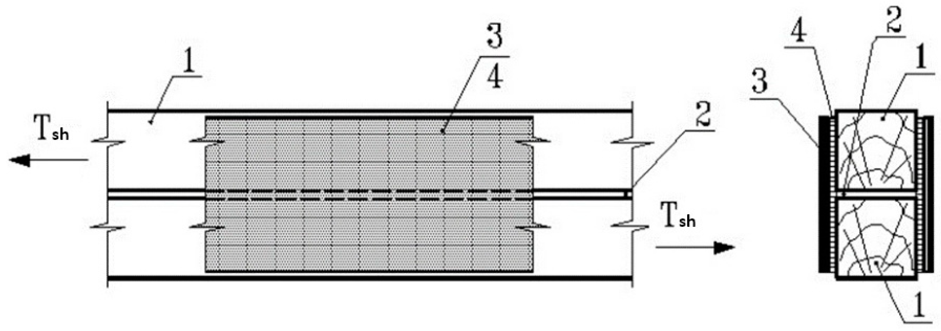
Figure 1. Jointing wooden elements with a composite material based on an epoxy matrix and fiberglass by externally gluing the side surfaces of the joined elements: 1—jointing wooden elements; 2—welding seam; 3—composite material formed on the structure; 4—pasting seam creating an adhesive joint at the fiberglass–wood interface.
Buildings 13 03063 g001
Figure 2. Samples of the fiberglass joint: 1—wooden elements 45 × 95 × 200 mm; 2—welding seam t = 1 mm; 3—gluing area in the joint; 4—temporary bonds, removed after polymerization of the epoxy matrix.
Buildings 13 03063 g002
Figure 3. General view of samples of the fiberglass joint types 1, 2, and 3 with gluing in 2, 4, and 6 layers.
Buildings 13 03063 g003
Figure 4. View of samples of 2-layer fiberglass joints during testing. Series 1.
Buildings 13 03063 g004
Figure 5. View of samples of 4-layer fiberglass joints during testing. Series 2.
Buildings 13 03063 g005
Figure 6. View of samples of 6-layer fiberglass joints during testing. Series 3.
Buildings 13 03063 g006
Figure 7. Shear resistance of the fiberglass compound depending on the thickness of the composite material: (a) fiberglass connection type 1 (KDA + T13); (b) fiberglass connection type 2 (PR + T13); (c) fiberglass connection type 3 (KDA + T13); (d) resistance to separation of fiberglass from the base.
Buildings 13 03063 g007
Table 1. Composition of polymer matrices for creating fiberglass connections.
No.ComponentsGOST, TUMass PartsPolymerization TemperatureTechnological Viability (t = 25 °C), min
1Resin KDA-MTU
2225-042-17411121-2008
100from +5 °C to +35 °C60
Hardener
Etal-45
TU 2257-045-18826195-0150
2Resin ED-20GOST 10587100Not lower than 18 °C to +35 °C30
Hardener
PEPA
TU 6-02-594-8010 ÷ 15
Plasticizer
DBP
GOST 87285 ÷ 10
3Polyester resin
PolyTay 303TAE
GOST 2795210020 °C120
Hardener
Butanox-M50
2.5
Table 2. List of samples of the fiberglass compound—1 series.
SeriesNo.Sample BrandConnection TypeNumber of
Layers
CompositionWood Grade Type
1
—samples of 2nd layer of fiberglass
1O-1-1-112 layersKDA/Etal 45 + T132
2O-1-1-21-- “ --KDA/Etal 45 + T13-- “ --
3O-1-1-31-- “ --KDA/Etal 45 + T13-- “ --
4O-2-1-122 layersPR/B-M50 + T132
5O-2-1-22-- “ --PR/B-M50 + T13-- “ --
6O-2-1-32-- “ --PR/B-M50 + T13-- “ --
7O-3-1-132 layersKDA/Etal 45 + RF2
8O-3-1-23-- “ --KDA/Etal 45 + RF-- “ --
9O-3-1-33-- “ --KDA/Etal 45 + RF-- “ --
-- “ -- means “the same number of layers”.
Table 3. List of samples of the fiberglass compound—2nd series.
SeriesNo.Sample BrandConnection TypeNumber of
Layers
CompositionWood Grade Type
2
—samples of 4th layer of fiberglass
10O-1-2-114 layersKDA/Etal 45 + T132
11O-1-2-21-- “ --KDA/Etal 45 + T13-- “ --
12O-1-2-31-- “ --KDA/Etal 45 + T13-- “ --
13O-2-2-124 layersPR/B-M50 + T132
14O-2-2-22-- “ --PR/B-M50 + T13-- “ --
15O-2-2-32-- “ --PR/B-M50 + T13-- “ --
16O-3-2-134 layersKDA/Etal 45 + RF2
17O-3-2-23-- “ --KDA/Etal 45 + RF-- “ --
18O-3-2-33-- “ --KDA/Etal 45 + RF-- “ --
-- “ -- means “the same number of layers”.
Table 4. List of samples of the fiberglass compound—series 3.
SeriesNo.Sample BrandConnection TypeNumber of
Layers
CompositionWood Grade Type
3
—samples of 6 layers of fiberglass
19O-1-3-116 layersKDA/Etal 45 + T132
20O-1-3-21-- “ --KDA/Etal 45 + T13-- “ --
21O-1-3-31-- “ --KDA/Etal 45 + T13-- “ --
22O-2-3-126 layersPR/B-M50 + T132
23O-2-3-22-- “ --PR/B-M50 + T13-- “ --
24O-2-3-32-- “ --PR/B-M50 + T13-- “ --
25O-3-3-136 layersKDA/Etal 45 + RF2
26O-3-3-23-- “ --KDA/Etal 45 + RF-- “ --
27O-3-3-33-- “ --KDA/Etal 45 + RF-- “ --
-- “ -- means “the same number of layers”.
Table 5. Test results of the first series of samples of the fiberglass compound.
Connection TypeSample Brandtmax
sec.
t = tmax/38.2
sec.
Lg t
sec.
Reliability CoefficientsNmax kN
γν
by Formula
Required
by NI-II
1O-1-1-174019.3721.2872.94 36
O-1-1-264416.8591.2272.95 33
O-1-1-383721.9111.3412.93 36.4
Avg.740 2.9371.335.13
2O-2-1-139310.2881.0122.99 24.1
O-2-1-239710.3931.0172.99 24
O-2-1-339310.2881.0122.99 24
Avg.394 2.9891.324.03
3O-3-1-1118531.0211.4922.90 47.8
O-3-1-255514.5291.1622.96 30
O-3-1-376319.9741.3002.93 36.1
Avg.834 2.9311.337.97
Table 6. Test results of the second series of samples of the fiberglass compound.
Connection TypeSample Brandtmax
sec.
t = tmax/38.2
sec.
Lg t
sec.
Reliability CoefficientsNmax kN
γν
by Formula
Required
by NI-II
1O-1-2-184522.1201.3452.93 39
O-1-2-284422.0941.3442.93 38.9
O-1-2-384622.1471.3452.93 39
Avg.845 2.9261.338.97
2O-2-2-184021.9901.3422.93 38.2
O-2-2-284322.0681.3442.93 38.9
O-2-2-385022.2511.3472.93 38.9
Avg.844 2.9261.338.67
3O-3-2-1185448.5211.6862.86 45
O-3-2-264316.8321.2262.95 33
O-3-2-395625.0261.3982.92 42
Avg.1151 2.9081.340.0
Table 7. Test results of the third series of samples of the fiberglass compound.
Connection TypeSample Brandtmax
sec.
t = tmax/38.2
sec.
Lg t
sec.
Reliability CoefficientsNmax kN
γν
by Formula
Required
by NI-II
1O-1-3-1159141.6491.6202.87 57
O-1-3-2131034.2931.5352.89 49.6
O-1-3-3118430.9951.4912.90 46.3
Avg.1326 2.8871.350.97
2O-2-3-194924.8431.3952.92 41.4
O-2-3-294324.6861.3922.92 39
O-2-3-3108528.4031.4532.92 45
Avg.992 2.9131.341.8
3O-3-3-1120031.4141.4972.90 48
O-3-3-2106227.8011.4442.91 43.4
O-3-3-375119.6601.2942.94 36
Avg.1004 2.9131.342.47
Table 8. Characteristics of strength and deformability of fiberglass compounds.
Type of FiberglassNumber of Layers Dp/Np
at the RNS ∗ Level of the Sample,
mm/kN
Resistance of the Fiberglass Joint to Shear
By the Area of the Shear RavgFGC, MPaLinear,
TFGC,
N/mm
Separation,
RsepFGC, MPa
Type 1 KDA + T132 layers0.0019933.2319.90.886
4 layers0.0019120.1822.20.987
6 layers0.0017818.4029.41.308
Type 2 PR + T132 layers0.0036219.2311,50.513
4 layers0.0025413.9915.40.684
6 layers0.0031312.0219.20.855
Type 3 KDA + RF2 layers0.0029536.0221.60.960
4 layers0.0024020.8723.01.020
6 layers0.0016215.2024.31.081
Table 9. Calculated resistance to the separation of the composite material from the wooden element Rsep·CM.
Type FiberglassThickness FiberglassRsep·FGC, MPa
KDA-M + T13 KDA-M + RFup to 1 mm0.9
from 1 mm to 1.6 mm1.0
more than 1.6 mm1.1
PR + T13up to 1 mm0.5
from 1 mm to 1.6 mm0.68
more than 1.6 mm0.85
Disclaimer/Publisher’s Note: The statements, opinions and data contained in all publications are solely those of the individual author(s) and contributor(s) and not of MDPI and/or the editor(s). MDPI and/or the editor(s) disclaim responsibility for any injury to people or property resulting from any ideas, methods, instructions or products referred to in the content.