Abstract
The mechanical property of the pile-core–cement-soil interface is a crucial factor affecting the shaft capacity of the expanded stiffened deep-cement-mixing (ESDCM) pile. The research on the characteristics of the steel-pipe–cement-soil interface is very limited, and the conventional concrete–cement-soil interface research results cannot provide direct guidance for the engineering application of the steel-pipe–cement-soil combination pile. Hence, in this study, we employed a model pile with a steel-pipe–cement-soil combination. By using a confining pressure transfer test and an inner interface shear test, the influence of confining pressure on the inner interface and shear deformation of the inner interface were investigated. The results demonstrated that the lateral confining pressure has almost no effect on the inner interface due to the encapsulation of the soil-cement column. The interface shear experienced four stages: the steel pipe small deformation, which is the extra stage compared to the common concrete–cement-soil combination form; the whole pipe compression; the brittle failure; and the shear-slip stage. The peak shear stress at the interface is 194 kPa, and the corresponding pile core top displacement and core bottom displacement are 5.9 mm and 5.4 mm, respectively. The inner interface bond coefficient is only 0.052, indicating that even the smooth steel pipe can work closely with the cement-soil at a low bonding coefficient. Further optimization of the steel-pipe–cement-soil interface structure can be an essential means to improve the mechanical properties of the pile. When the upper load is transferred downward, it spreads around through the cement-soil, and as the load increases, the load that can finally be transferred to the deep part accounts for a relatively small amount, only about 7%. This work promotes the understanding of the interface mechanical properties of ESDCM piles and guides the application of an ESDCM pile with a steel core in practical engineering.
1. Introduction
Soft soils are widely distributed along rivers and coastal areas of China [1,2,3]. The drawbacks of the soil, including low strength, high compressibility, and poor permeability [4], makes it difficult for traditional engineering pile types to meet the requirements of bearing capacity and settlement effectively and economically for engineering construction [5,6]. The expanded stiffened deep-cement-mixing (ESDCM) pile is a new technology that has emerged and developed rapidly in recent years. It is a new type of composite pile with an expanding shape and mechanical characteristics that is formed by concentrically sinking a rigid pile core into a soil-cement column and expanding the body through a cement mixing pile or core pile [7]. The basic structures of ESDCM piles are demonstrated in Figure 1. According to the relationship between rigid pile core length lcs and soil-cement column length lcp, the ESDCM piles can be divided into the long core pile (lcs < lcp) and equal-length core pile (lcs ≈ lcp) [8]. Compared with the single “pile-soil” interface of conventional piles, the ESDCM pile has a double interface: an outer interface consisting of “soil–cement-soil” and an inner interface consisting of “core-pile–cement-soil” [9].
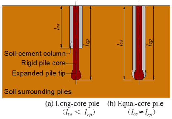
Figure 1.
Basic structures of expanded stiffened deep-cement-mixing piles.
In recent decades, a series of experimental studies, including field tests [10,11,12] and indoor model tests [13,14,15,16,17], have been conducted by domestic and foreign scholars to investigate the composite-pile-bearing mechanism and interface mechanical properties [18]. Dong et al. [19] found that when the SDCM pile bears the vertical load, the load transfer process from top to bottom forms a “two-layer diffusion pattern”, i.e., diffusion from the inner core to the outer core (inner layer) and diffusion from the outer core to the soil around the pile (outer layer). Wu [20] defined the inner-core–outer-core contact surface as the “first interface”, and the outer-core–soil-contact surface as the “second interface”. He conducted an indoor model test, determining that the shear strength of the first interface was about 0.194 times the compressive strength of the cement-soil of the outer core. Zhou et al. [21] conducted a series of interface shearing tests to study the frictional capacity of the concrete–cement-soil interface and the cement-soil–sandy-soil interface of the static drill rooted nodular pile, finding that the peak shear stress of the concrete–cement-soil interface was mainly controlled by the cohesion and friction angle of cement-soil [22], and the ratio of peak shear stress and the compressive strength of the cement-soil ranged from 0.116 to 0.141; the maximum shear strength of concrete–cement-soil interface was much higher than that of cement-soil–sandy-soil interface under the same condition [23].
Several scholars have also studied the composite pile using numerical simulations [24]. Tanchaisawat et al. [25] reported that the cement ratio had a significant influence on the shear strength of the cement-soil interface, and the normal stress on the interface and the ratio of the cross-sectional area of the core pile to the cement-soil pile also affected the shear strength of the interface, but not as significantly as the cement ratio did. Voottipruex et al. [26] investigated the bearing mechanism of SDCM piles in the form of numerical simulation based on field tests. Zhu et al. [27] proposed a theoretical method for analyzing the load transfer of SDCM piles in layer soils, then conducted model tests and three-dimensional finite element simulations. The results showed that the predictions were in reasonable agreement with the simulated and experimental results, and the theoretical method had good applicability. Wonglert et al. [28] also investigated the effect of pile core stiffness on the performance of SDCM piles by means of numerical simulation.
However, the above-mentioned studies on the inner interface mostly focused on the concrete–cement-soil interface [29]. Concrete pile cores often fail to meet the strength and weight requirements when dealing with hard soil layers, or when pile foundation projects require light weight and miniaturization; in those cases, it is necessary to seek a more optimal pile core material. In addition, in earthquake-prone areas, the selection and design of concrete structures is also often limited and requires careful consideration [30,31]. Steel pipes are widely used in engineering construction because of their high strength, high bending resistance, good elasticity, and easy manufacturing and construction. They few scholars who have studied the steel-pipe–cement-soil interface have only conducted a simple quantitative study of the shear stress at the interface [32]. In addition, the model box interface straight shear approach that some researchers have taken is traditional [33], which was different from the actual cross-section of the pile. The application of the scale model tests also often ignored the extrusion effect of the outer confining pressure, which was significant in practical projects [34]. The formation mechanism of shear strength at the pile core–cement-soil interface, as well as the mechanism of evolution of frictional resistance at both interfaces when the composite pile was deformed and damaged under the vertical ultimate load, are not clear from the current reports [35,36,37]. Therefore, it is necessary to conduct a more in-depth study on the mechanical properties of the inner interfaces of the ESDCM pile [38,39,40].
In this study, we focused on the steel-pipe–cement-soil composite ESDCM pile and investigated the influence of the outer confining pressure on the mechanical performance of the inner interface via a series of laboratory large-scale model tests. Firstly, we designed a confining pressure transfer test to investigate the influence of the outer confining pressure of the ESDCM pile on the inner interface after transferring through the soil-cement column. Afterward, we carried out a shear test at the steel-pipe–cement-soil interface. Based on the stress-displacement relationship curves of the inner interface of the model composite pile, we analyzed the deformation law of the inner interface of the ESDCM pile.
2. Experimental Methods
2.1. Fabrication of Test Models
2.1.1. Model Pile Preparation
The test soil was taken from the sandy powder soil at a depth of about 4 m below ground level in Nantong City, Jiangsu Province, China. The physical and mechanical indexes of the original soil are exhibited in Table 1.

Table 1.
The physical and mechanical indexes of the test soil.
The schematic diagram of the physical model barrel and the model pile are shown in Figure 2. This shows that the core pile of the model pile was made of seamless steel pipe, with an outer diameter of 108 mm, a wall thickness of 5 mm, a length of 1200 mm, and an elastic modulus (E) of 200 GPa. The pouring formwork was made of PVC pipe with an inner diameter of 192 mm, a length of 1000 mm, and a wall thickness of 4 mm. The design cement content of the model pile was about 15% and the water-cement ratio was 0.4. Since the test in this work focused on the mechanical properties of the steel-pipe–cement-soil interface, for the convenience of loading and monitoring during the test, the expanded pile head was not set. The steel pipe was exposed to a certain length at both ends and the length of the composite segment was 800 mm. Compared with the size of the ESDCM pile employed in practical projects, the scale ratios of the diameter and length were approximately 1/4.5 and 1/7.5, respectively. A steel oil barrel was used as the test model barrel, with a height of 890 mm, a bottom diameter of 600 mm, and a wall thickness of 5 mm. Before the test, a hole was opened at the center of the bottom of the barrel, and the size of the hole was slightly larger than the diameter of the steel pipe to ensure that the steel pipe passed through it smoothly during the test.
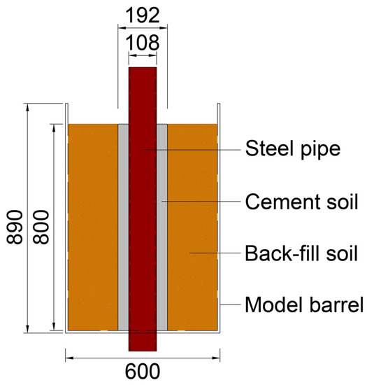
Figure 2.
Schematic diagram of model size (mm).
2.1.2. Pressure Ring
The confining pressure transferring test required the application of vertical load to the outer fill of the pile inside the model bucket. To ensure the uniformity of the load, the pressure ring was customized as shown in Figure 3. The size of the pressure ring should be between the inner diameter of the barrel and the diameter of the model pile, and a certain operating space should also remain. Therefore, the outer diameter of the pressure ring was designed to be 500 mm, the inner diameter was 245 mm, and the thickness was 20 mm.
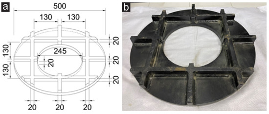
Figure 3.
(a) Dimensions (mm) and (b) physical drawing pressure ring.
The pressure ring was machined with 45# manganese steel. First, the ring was cut out by laser on the steel plate, and then the square steel with a section of 20 mm × 20 mm was welded at equal intervals in the transverse and longitudinal directions at the bottom of the ring to ensure the compressive strength of the pressure ring. After welding, black paint was sprayed on the surface of the pressure ring to prevent rust. The machining process is undertaken by professional metal processing institutions.
2.2. Test Platform
2.2.1. Construction of Test Platform
The test platform was constructed using a jacking beam, as presented in Figure 4a. The construction processes were as follows. First, we placed the model barrel on the bearer and then used a small crane to slowly lift the model pile into the barrel. This was done carefully to ensure that the steel pipe passed smoothly through the hole. Next, a level was used to control the levelness and verticality of the model pile. At the same time, the gap in the barrel was filled with soil, which was filled and rammed 6 times, until the soil covered the top of the soil-cement column of the model pile. After filling, the pressure ring was concentric with the model pile and placed horizontally above the soil mass. Then, the jacking beam was adjusted to a suitable height, and the oil-pressure jacks and loading sensing cells were placed symmetrically on the pressure. The jacks were slowly lifted until their tops were slightly against the jacking beam, and the platform construction was completed. During the interfacial shear test, one more jack was also placed on top of the steel pipe core to apply the upper load. The built test platform is shown in Figure 4b.
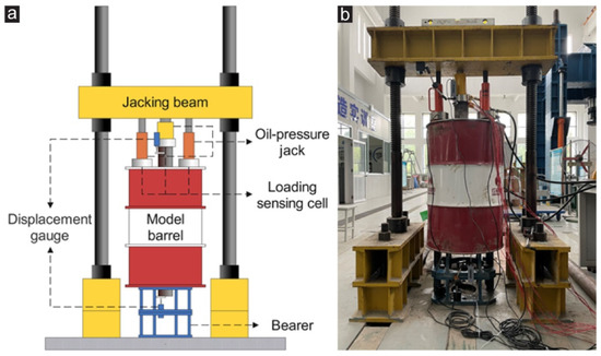
Figure 4.
Construction of the test platform (a) design diagram and (b) practical test platform.
2.2.2. Test Apparatus
To investigate the inner interface mechanical properties of the ESDCM pile, train gauges were pasted along the axial direction and soil pressure cells were arranged at five sections of the outer wall of the steel pipe at the expected burial depths of 8 cm, 24 cm, 40 cm, 56 cm, and 72 cm (Figure 5) before casting the model pile. The soil pressure cells were arranged in each section at 180° alternately. In addition, two more strain gauges were pasted along the horizontal direction at the 24 cm and 56 cm depths of the cross-section. An epoxy resin cover was used as the outer protective layer on the strain gauges to prevent them from moisture short-circuiting during the model pile casting process. Holes were drilled in advance at sections where the steel pipe was expected to be buried, i.e., at 0 cm, 16 cm, 32 cm, 48 cm, and 64 cm. The wires of the strain gauges and soil pressure cells were led from the nearest borehole through the inside of the steel pipe to reduce the influence of the wires on the inner interface structure. After the model pile was poured, cured, shaped, and demolded, soil pressure cells were arranged at the same cross-section of the soil-cement column’s outer wall.
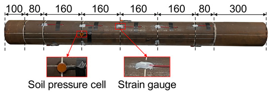
Figure 5.
Embedded strain gauges and soil pressure cells (mm).
After the test platform was built, nylon plates were pasted at the bottom of the steel pipe and near the top of the pipe as the touch planes of the displacement gauges. Displacement gauges were arranged in these two planes for accurate measurement of pile deformation displacement (Figure 6); load sensors were laid underneath the jacks to monitor the applied load in real time.
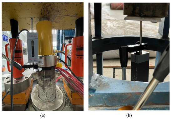
Figure 6.
Displacement gauges (a) near the top of the steel pipe and (b) at the bottom of the steel pipe.
2.3. Test Method
The overall flow of the test is shown in Figure 7. When pouring the model pile, test cube specimens of size (70.7 mm × 70.7 mm × 70.7 mm) were cast at the same time. When the test cube specimens were cured to the 7th, 14th, 28th, and 90th day, the unconfined compressive strength test of cement-soil was carried out according to the standard “Specification for mix proportion design of cement-soil” (JGJ/T 233-2011) [41]. When the specimens had cured for 90 days, the model pile was lifted and the test platform was set up, and then the confining pressure transfer test and the steel-pipe–cement-soil interface shear test were conducted.
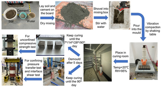
Figure 7.
Preparation processes of the ESDCM Pile and corresponding measurements.
2.3.1. Confining Pressure Transfer Test
This test was designed to investigate the influence of the outer confining pressure of the ESDCM pile on the inner interface after transferring through the soil-cement column. The test was divided into two stages: the first stage was the monitoring of confining pressure at the inner and outer interfaces during the filling process. Once the model pile position was calibrated during platform construction, the soil pressure cells were connected to the dynamic collector (Figure 8) to record the trend of confining pressure at the inner interface and the outer interface of the model pile during the filling process. After the completion of filling, the test platform was left to stand for about 14 h, followed by the second stage of the test, i.e., the monitoring of confining pressure at both interfaces of the model pile under the upper load on soil. Since the data could be substantially poor after the soil pressure cells had been resting for a long period, they were zeroed before the second stage so that the confining pressure monitored during the second stage could be considered to originate entirely from the transfer of the upper load.
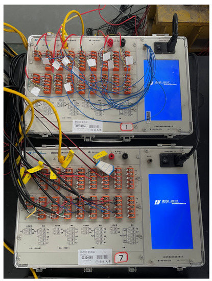
Figure 8.
The dynamic collector.
As shown in Figure 9, during the test, the jacks on the pressure ring were lifted synchronously, and the vertical load would be applied to the soil below the ring under the reverse action of the jacking beam; the load would then be transferred by the soil to form lateral confining pressure on the outside of the model pile to simulate the lateral confining pressure condition of the composite pile in practical projects. The test used the slow maintenance loading method, taking the classification of 5 kN, and the maintenance time for each level of the load was not less than 60 min. When the data monitored by the soil pressure cells reached a relatively stable state, the next level of loading could be executed, and the loading was stopped either when the soil was compressed to the top of the soil-cement column, or when the load could no longer be increased.
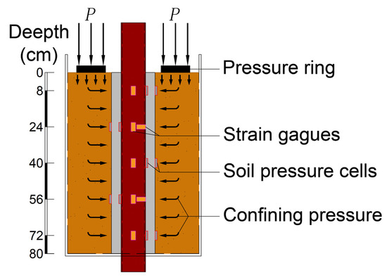
Figure 9.
Confining pressure transfer test schematic diagram.
2.3.2. Steel-Pipe–Cement-Soil Interface Shear Test
After the completion of the confining pressure transfer test, the jack load was maintained, a load sensor and a jack were placed on the top of the pile, and the shear test was carried out on the steel-pipe–cement-soil interface (inner interface). The test still used the slow maintenance loading method, and the loading method was carried out with reference to the relevant provisions of the standard “Technical code for testing of building piles” (JGJ 106-2014) [42]. The graded load was taken as 1/10 of the ultimate bearing capacity of the model pile. The test aimed to investigate the mechanical properties of the inner interface. The influence of the expanded pile tip on the bearing capacity had been eliminated when pouring the model pile and building the platform, so the predicted bearing capacity of the model pile was about 30 kN, so the graded load was taken as 3 kN. The maintenance time of each load level was about 60 min, and if the monitoring data reached a relatively stable state, the next level of loading was carried out. The loading was stopped when the displacement of the pile top reached 40 mm, or when the pile body was significantly damaged.
3. Results and Discussion
3.1. Unconfined Compressive Strength Test
The unconfined compressive strength test results are exhibited in Table 2. The results show that, in the three parallel tests of each group, the measured unconfined compressive strengths of the test blocks have an aberration of less than 15% from the average value. The standard deviations of the results are small for all groups, and the dispersion of the results is low. Therefore, the arithmetic mean of the three measurements is taken as the unconfined compressive strength value of the cement-soil at each age. With a cement ratio of 15% and water-to-ash ratio of 0.4, the early strength of the cement-soil material progresses relatively rapidly, reaching 62.3% of the 90th day strength on the 7th day, then the growth in strength of the cement-soil material gradually slows down, with 21.7% growth in strength from the 7th to the 14th day, 19.4% from the 14th to the 28th day and only 10.3% increase in strength from the 28th to the 90th day.
Table 2.
Statistics of unconfined compressive strength test results.
3.2. Confining Pressure Transfer Test
The variation trend of the confining pressure at different depths of the inner and outer interfaces of the model pile during the filling process (the first stage) are demonstrated in Figure 10. In the early stage of filling, although there are disturbance changes of different amplitudes, the lateral confining pressures on the outer interface of the model pile show an overall increasing trend, and the confining pressures at the inner interface are in a slightly disturbed state throughout the whole process. During the filling process, the external core of the soil cement bore almost all the lateral confining pressure.
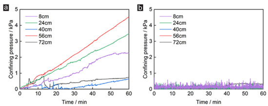
Figure 10.
Variation curves of confining pressure of the (a) outer and (b) inner interfaces during the filling process.
In the second stage of the test, when the upper soil load reaches 50 kN, the bottleneck stage is entered. At this time, the pressure jack can no longer lift the load value, and the soil around the pressure ring begins to bubble out under pressure, so the loading is stopped, and the test is finished, as shown in Figure 11. After each stage of loading, the compression of the soil and the pressure venting of the jacks will cause the load to rise and then slide off before eventually leveling off to a relatively stable state. At the stage of applying load to the soil around the pile, with the increase of the upper load, the lateral confining pressure of the model pile is gradually transferred to the inner interface. As the outer interface has a degree of void space at different depths, the outer confining pressures fluctuate to varying degrees, but the overall trend is consistent with that of the upper soil load. Along the longitudinal depth, although the inhomogeneity of the soil density around the pile results in irregular fluctuations in the lateral confinement when monitored at certain depths, the overall confining pressure to the outer interface is found to increase with depth.
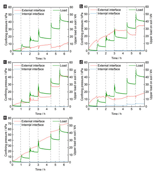
Figure 11.
Variation curves of confining pressure of the external and inner interfaces with the upper load on soil at different depths: (a) 8 cm; (b) 24 cm; (c) 40 cm; (d) 56 cm; (e) 72 cm.
For the outer interface, the earth pressure sensor is buried at a shallow depth of 8 cm, and the external confining pressure is relatively low at that depth. The soil pressure cells at the burial depths of 8 cm and 24 cm are both in the influence range of the pressure ring, and soil spills out of the pressure ring successively during the loading process, resulting in a steep drop and then a rise in the confining pressure curves at these two locations on the outer interface for nearly every loading stage. The lateral confining pressure curve at 40 cm burial depth is well synchronized with the load changes; the lateral confining pressure at 56 cm burial depth fluctuates around 15 kPa after an initial rise, presumably because of uneven soils and possible soil layering gaps. The lateral confining pressure at a burial depth of 72 cm increases continuously with increasing load and does not appear to decrease even with unloading, presumably because it is at a deeper part of the soil and is supported by the support reactions, giving it a higher degree of soil consolidation.
The inner interface, on the other hand, is not influenced by the lateral pressure of the outer interface throughout the entire process, except for a small increment of the inner interface confining pressure with the upper soil load at a burial depth of 56 cm, as it is located inside the semi-rigid and homogeneous soil-cement column. Combining the above two stages of internal and outer interface force conditions, it can be concluded that the semi-rigid soil-cement column as a transition layer resists more than 95% of the lateral confinement well; it substantially reduces the influence of horizontal lateral confining pressure on the pile core and ensures the vertical load-bearing capacity of the pile core.
3.3. Shear Test at the Steel-Pipe–Cement-Soil Interface
The shear test of the steel-pipe–cement-soil interface was then carried out according to the test protocol. Before the test, the core pile was first preloaded by 1.5 kN to hold the jack in place. During the test, the horizontal strain gauges attached to the steel pipe, as well as the vertical strain gauges at the buried depths of 24 cm and 40 cm, did not work properly, probably due to damage; the variation values of the strain gauges at the buried depths of 8 cm, 56 cm, and 72 cm with the top load of the pile are shown in Figure 12.
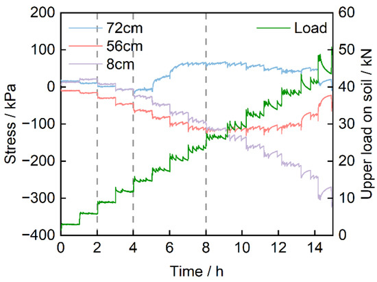
Figure 12.
Variation curves of stress with upper load on soil at different buried depths.
The strain gauge at a depth of 8 cm undergoes a period of tension during the first 2 levels of loading and enters a state of compression from the third level of loading. The strain gauge, buried at a depth of 56 cm, begins to change from compression to tension at the fifth load level and stabilizes gradually at the seventh load level, presumably because the gauge is partially detached from the steel pipe by friction at level five and is completely stripped at level seven. The strain gauge at a depth of 72 cm stabilizes from level nine, presumably due to the stripping of the gauges from the pipe at this point.
The shearing stress-displacement curve of the steel-pipe–cement-soil interface is shown in Figure 13. Based on the typical side friction resistance–relative displacement curve [43], combined with the test results, the shearing process at the steel-pipe–cement-soil interface can be divided into four stages: the small deformation stage of the steel pipe, the compression stage of the whole pipe, the brittle failure, and the shear-slip stage, as exhibited in Figure 14.
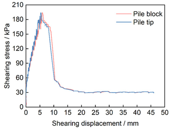
Figure 13.
Shearing stress-displacement curve of steel-pipe–cement-soil interface.
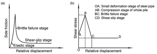
Figure 14.
(a) Typical side friction resistance–relative displacement curve. (b) Four stages of steel pipe–cement-soil interface shear.
Compared with the composite pile in the form of a conventional concrete–cement-soil combination [44], the inner interface of the steel-pipe–cement-soil combination undergoes one more stage in shear. At the preliminary stage of loading, the shear stress at the inner interface increases step by step with the load, and the steel pipe core enters the elastic stage first before the soil-cement column, that is the OA section. However, as the load is relatively low at this time, the modulus of elasticity of steel pipe is relatively large, meaning that the compression of the steel pipe is extremely minor. The steel pipe and soil-cement column are tightly bonded, and no relative displacement occurs.
When the load is lifted to 12 kN and the shear stress reaches 44 kPa, the steel-pipe–cement-soil interface shear enters the elastic phase, that is, the AB section. During this stage, the soil-cement column is compressed together with the pile core (steel pipe), after which the shear stress and shear displacement remain essentially linear until the ultimate peak is reached. The peak shear stress is 194 kPa, corresponding to a shear displacement of 5.4 mm at the bottom of the pile core and 5.9 mm at the top of the pile core. The compression at the top of the core is larger than the compression at the bottom. A distinct sound can be detected coming from the model barrel before and after the peak, which should be damage from the soil-cement column body and a massive peeling of the steel pipe and cement-soil.
In soil mechanics, the Mohr–Coulomb model is widely used because it can obtain fairly reliable results within a certain lateral limit stress range and is easy to use. Several scholars have also demonstrated by direct shear tests that Mohr–Coulomb law can express the mechanical interaction between the cement-soil and the core pile material well [45]. Based on this, in combination with the results of the confining pressure transfer test and the data obtained, we can use a more intuitive index to evaluate the bonding property of the inner interface.
The ratio of peak shear stress to unconfined compressive strength of cement-soil is defined as the bonding coefficient, which can be calculated according to the following arithmetic expression:
In the above formula, is the bond coefficient is the interface peak shear stress, and is the unconfined compressive strength of cement-soil. In this paper, the peak shear stress is 194 kPa, the unconfined compressive strength of cement-soil is the value of the test day, that is, the average strength of the 90th day was 3.753 MPa, and the interfacial bond coefficient = 194/3753 = 0.052. Compared with the concrete core pile [46], the bonding coefficient of smooth steel pipe and cement-soil is low, but the two have been working closely and synergistically during the whole compression process, and the whole pile still shows excellent load-bearing performance. The structure of the interface, such as roughness, often has a large influence on the mechanical properties of the interface [47]. Therefore, in future research, the load-bearing potential of the pile will be further enhanced if the structure of the inner interface is optimally designed.
After the peak, the interface shear proceeds to the brittle failure stage, the BC section. Within this stage, as the relative displacement of the steel pipe and soil-cement column further enlarges, the shear stress at the inner interface gradually decreases, the loading process keeps emitting a bursting sound, and the soil-cement column experiences growing damage, until the steel-pipe–soil-cement-column completely strips and loses the limits of the bond. The top and bottom of the steel pipe displacement gradually converges, and the steel pipe enters the shear-slip stage, that is, the CD section. The steel pipe is compressed, and sliding friction in the soil-cement column and the shear stress gradually remains stable as the relevant displacement grows; this is referred to as residual shear stress.
When the test was completed, the fill was excavated and the model pile was extracted from the soil. The steel pipe core had been completely stripped from the soil-cement column, and the column body was found to be broken into three major parts by three cracks through the pile body, part of which further split into smaller cement-soil pieces at the top, which resulted in brittle damage in the entire pile, as shown in Figure 15. This form of damage is different from the common form of pile damage that occurs in actual engineering. In actual engineering, pile damage mainly manifests as integral shear damage [48] or piercing damage to the pile body [49], and the cracks produced by damage and fracture are mostly local cracks [50]. Penetration cracks such as those shown in the figure rarely occur. This may occur because, in this paper, the pile core (steel pipe) was allowed to bear the full vertical load instead of being subjected to compression together with the outer soil-cement column in the actual project, and the displacement of the soil-cement column is artificially restricted in the test. Therefore, when the steel pipe is loaded, the soil-cement column is gradually driven by the steel pipe from the top to produce compression, and the bottom cannot be moved due to the restriction of the model barrel, so the soil-cement column is subjected to compression at the top and bottom at the same time. Because of the expansion and compression of the steel pipe core, the soil-cement column expands and shear expansion occurs, resulting in cracks from the inner interface that gradually move to the outside, eventually forming multiple penetration cracks leading to pile damage.
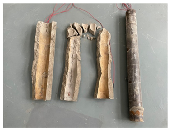
Figure 15.
Model pile failure diagram.
The distribution of the axial force of the core pile is shown in Figure 16. Among these, axial force data are missing at 24 cm and 40 cm depths. Since the length of the model pile is relatively small compared to the real pile, the axial forces are distributed more evenly and smoothly inside the pile core, but it can still be seen that the axial forces at the deeper part of the pile tend to decrease with increasing vertical depth. During the test, the steel pipe core takes up all the vertical loads, which are spread around the pile in a top-down transfer process through the transition layer of the cement-soil, and eventually to the depth. At the initial stage of loading, due to the relatively light load, the load was distributed more evenly in the pile body, and the percentage of load transferred to the bottom was about 35%. However, the percentage gradually reduced to 7% as the load on the top of the pile increased.
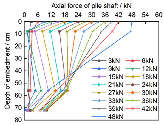
Figure 16.
Distribution of axial force of pile shaft.
4. Conclusions and Outlooks
The double interface is one of the characteristics that distinguish the ESDCM pile from traditional piles, and the mechanical properties of the inner and outer interfaces are an important basis for the load-bearing performance of the pile. In this work, a series of tests have been conducted to investigate the effect of the presence of the outer soil-cement column on the transfer of the lateral confining pressure and the shear mechanical properties of the inner interface for a rare combination of steel-pipe–cement-soil composite pile, and the following conclusions have been obtained.
- (1)
- In the confining pressure transfer test, the semi-rigid soil-cement column, as a transition layer, resists more than 95% of the lateral confining pressure well and substantially reduces the influence of confining pressure on the pile core, which ensures the stability of the vertical load-bearing performance of the pile core. In the shear test at the steel-pipe–cement-soil interface, the shear process can be divided into four stages: the small deformation stage of the steel pipe, which is the extra stage compared to the common concrete–cement-soil combination form; the compression stage of the whole pipe; the brittle failure stage; and the shear-slip stage.
- (2)
- With the low load, the steel pipe and cement-soil were tightly bonded and did not produce relative displacement. In the elastic compression stage, the soil-cement column is compressed simultaneously with the steel pipe core, and the shear stress and shear displacement remain basically linear until reaching the ultimate peak of 194 kPa, which corresponds to the displacement of 5.4 mm and 5.9 mm at the bottom and top of the pile, respectively. In the brittle failure stage, the relative displacement of steel pipe and the soil-cement column further increases, the inner interface shear stress gradually decreases, and steel pipe and soil-cement column gradually strip altogether, entering the shear slip stage. Shear stress with the relative displacement growth gradually remains stable.
- (3)
- The steel-pipe–soil-cement-column bonding performance is considered satisfactory. Most of the time, the pipe and the column maintain a state of collaboration. For the ESDCM pile with steel pipe core, the bond strength of the steel-pipe–cement-soil interface is roughly 0.052 times the strength of the cement-soil. The smooth steel pipe can work closely with the cement-soil even at a low bonding coefficient. Further optimization of the steel-pipe–cement-soil interface structure can be an important way to improve the load-bearing potential of the pile. Eventually, when the steel-pipe–cement-soil interface breaks down, multiple large cracks penetrate the soil-cement column body, the steel pipe and the soil-cement column separate, and brittle damage occurs throughout the pile.
- (4)
- The steel pipe core undertakes all the upper loads, and the loads are evenly distributed inside the steel pipe core during the downward transfer process, spreading to the surrounding area through the transition layer of cement-soil, but the final load that can be transferred to the deep part is minor in comparison, accounting for only about 7% of the top load of the pile.
In future research, based on existing work, we will optimize the design of the interface structure by either adjusting the roughness of the steel pipe surface or adding steel ribs to obtain better bonding properties. In addition, more intrinsic models, such as the modified Cam–Clay (MCC) model, will be attempted to better describe the shear deformation under sandy soil media.
Overall, this research demonstrates the mechanical properties of the steel-pipe–cement soil interface. It may assist the audience to better understand the load-bearing capacity of the ESDCM pile from the theoretical aspect and also provide guidance in the design and construction of pile foundations in engineering.
Author Contributions
H.B., J.P. and Z.C. conceived and designed the experiments; H.B. and J.P. performed the experiments; J.P. and J.H. analyzed the data; H.B. and J.P. wrote the original draft; J.P., Z.C. and Y.G. reviewed and edited the manuscript. All authors have read and agreed to the published version of the manuscript.
Funding
This study was supported by the Natural Science Foundation of the Jiangsu Higher Education Institutions of China under Grants (22KJB560010), Postgraduate Research & Practice Innovation Program of Jiangsu Province (KYCX21_3090) and Basic science foundation of Nantong under Grants (JC22022102, JC12022098).
Data Availability Statement
No new data were created or analyzed in this study. Data sharing is not applicable to this article.
Conflicts of Interest
The authors declare that they have no known competing financial interest or personal relationship that could have appeared to influence the work reported in this paper.
References
- Gu, M.; Cai, X.; Fu, Q.; Li, H.; Wang, X.; Mao, B. Numerical Analysis of Passive Piles under Surcharge Load in Extensively Deep Soft Soil. Buildings 2022, 12, 1988. [Google Scholar] [CrossRef]
- Zhou, Q.; Zhang, H.; Fu, C.; Zhou, Y.; Dai, Z.; Li, Y.; Tu, C.; Luo, Y. The distribution and morphology of microplastics in coastal soils adjacent to the Bohai Sea and the Yellow Sea. Geoderma 2018, 322, 201–208. [Google Scholar] [CrossRef]
- Huang, Y.; Jiang, X. Field-observed phenomena of seismic liquefaction and subsidence during the 2008 Wenchuan earth-quake in China. Nat. Hazards 2010, 54, 839–850. [Google Scholar] [CrossRef]
- Ferreira, T.M.; Mendes, N.; Silva, R. Multiscale Seismic Vulnerability Assessment and Retrofit of Existing Masonry Buildings. Buildings 2019, 9, 91. [Google Scholar] [CrossRef]
- Coduto, D.P. Foundation Design; Pomona, California State Polytechnic University: San Luis Obispo, CA, USA, 2001. [Google Scholar]
- Day, R.W. Foundation Engineering Handbook: Design and Construction with the 2009 International Building Code; McGraw-Hill Education: New York, NY, USA, 2010. [Google Scholar]
- Shu, B.; Gong, H.; Chen, S.; Ren, Y.; Li, Y.; Yang, T.; Zeng, G.; Zhou, M.; Barbieri, D.M.; Li, Y. Case Study of Solid Waste Based Soft Soil Solidifying Materials Applied in Deep Mixing Pile. Buildings 2022, 12, 1193. [Google Scholar] [CrossRef]
- Voottipruex, P.; Bergado, D.; Suksawat, T.; Jamsawang, P.; Cheang, W. Behavior and Simulation of Deep Cement Mixing (DCM) and Stiffened Deep Cement Mixing (SDCM) Piles Under Full Scale Loading. Soils Found. 2011, 51, 307–320. [Google Scholar] [CrossRef]
- Zhang, C.; Liu, S.; Zhang, D.; Lai, F.; Lu, T.; Liu, Y. A modified equal-strain solution for consolidation behavior of composite foundation reinforced by precast concrete piles improved with cement-treated soil. Comput. Geotech. 2022, 150, 104905. [Google Scholar] [CrossRef]
- Zhou, J.-J.; Gong, X.-N. A field study on the behavior of static drill rooted nodular piles with caps under compression. J. Zhejiang Univ. A 2015, 16, 951–963. [Google Scholar] [CrossRef]
- Ren, L.; Kong, G. Analysis on bearing capacity calculation and adjustment factor of JPP pile. In Proceedings of the 2011 International Conference on Electric Technology and Civil Engineering (ICETCE), Lushan, China, 22–24 April 2011. [Google Scholar]
- Wang, C.; Xu, Y.; Dong, P. Plate Load Tests of Composite Foundation Reinforced by Concrete-Cored DCM Pile. Geotech. Geol. Eng. 2013, 32, 85–96. [Google Scholar] [CrossRef]
- Zhou, J.-J.; Gong, X.-N.; Wang, K.-H.; Zhang, R.-H.; Yan, T.-L. A Model Test on the Behavior of a Static Drill Rooted Nodular Pile Under Compression. Mar. Georesources Geotechnol. 2015, 34, 293–301. [Google Scholar] [CrossRef]
- Zhou, M.; Li, Z.; Han, Y.; Ni, P.; Wang, Y. Experimental Study on the Vertical Bearing Capacity of Stiffened Deep Cement Mixing Piles. Int. J. Géoméch. 2022, 22, 04022043. [Google Scholar] [CrossRef]
- Han, Y.; Cheng, J.; Zhou, M.; Ni, P.; Wang, Y. Experimental Study of Compaction and Expansion Effects Caused by Penetration of Core Pile During Con-struction of SDCM Pile. Int. J. Geomech. 2022, 22, 04022041. [Google Scholar] [CrossRef]
- Hossain, M.A.; Yin, J.-H. Dilatancy and strength of an unsaturated soil-cement interface in direct shear tests. Int. J. Geomech. 2015, 15, 04014081. [Google Scholar] [CrossRef]
- Jamsawang, P.; Bergado, D.; Bandari, A.; Voottipruex, P. Investigation and simulation of behavior of stiffened deep cement mixing (SDCM) piles. Int. J. Geotech. Eng. 2008, 2, 229–246. [Google Scholar] [CrossRef]
- Li, Y.; Sun, L.; Li, X.; Huang, M. Experimental study on the shear mechanical properties of the cemented soil–concrete interface. Eur. J. Environ. Civ. Eng. 2021, 26, 4725–4739. [Google Scholar] [CrossRef]
- Dong, P.; Qin, R.; Chen, Z. Bearing capacity and settlement of concrete-cored DCM pile in soft ground. Geotech. Geol. Eng. 2004, 22, 105–119. [Google Scholar] [CrossRef]
- Wu, M.; Zhao, X. Bearing Behaviors of Stiffened Deep Cement Mixed Pile. Trans. Tianjin Univ. 2006, 12, 209–214. [Google Scholar]
- Zhou, J.; Yu, J.; Gong, X.; El Naggar, M.H.; Zhang, R. The effect of cemented soil strength on the frictional capacity of precast concrete pile–cemented soil interface. Acta Geotech. 2020, 15, 3271–3282. [Google Scholar] [CrossRef]
- Liu, H.; Zhu, M.; Li, X.; Dai, G.; Yin, Q.; Liu, J.; Ling, C. Experimental Study on Shear Behavior of Interface between Different Soil Materials and Concrete under Varia-ble Normal Stress. Appl. Sci. 2022, 12, 11213. [Google Scholar] [CrossRef]
- Alanazi, M.J.; Qinghua, Y.; Al-Bukhaiti, K. Performance Study of Buried Pipelines under Static Loads. Civ. Eng. J. 2022, 8, 1–23. [Google Scholar] [CrossRef]
- Zhou, J.-J.; Wang, K.-H.; Gong, X.-N.; Zhang, R.-H. Bearing capacity and load transfer mechanism of a static drill rooted nodular pile in soft soil areas. J. Zhejiang Univ. A 2013, 14, 705–719. [Google Scholar] [CrossRef]
- Tanchaisawat, T.; Bergado, D.; Voottipruex, P. Numerical simulation and sensitivity analyses of full-scale test embankment with reinforced lightweight geomaterials on soft Bangkok clay. Geotext. Geomembr. 2008, 26, 498–511. [Google Scholar] [CrossRef]
- Voottipruex, P.; Suksawat, T.; Bergado, D.; Jamsawang, P. Numerical simulations and parametric study of SDCM and DCM piles under full scale axial and lateral loads. Comput. Geotech. 2011, 38, 318–329. [Google Scholar] [CrossRef]
- Zhu, S.; Chen, C.; Cai, H.; Mao, F. Analytical modeling for the load-transfer behavior of stiffened deep cement mixing (SDCM) pile with rigid cap in layer soils. Comput. Geotech. 2022, 144, 104618. [Google Scholar] [CrossRef]
- Wonglert, A.; Jongpradist, P. Impact of reinforced core on performance and failure behavior of stiffened deep cement mixing piles. Comput. Geotech. 2015, 69, 93–104. [Google Scholar] [CrossRef]
- Zhang, S.; Fan, Y.; Shah, S.P. Study on Deformation Characteristics and Damage Model of NMK Concrete under Cold Environment. Buildings 2022, 12, 1431. [Google Scholar] [CrossRef]
- Brunesi, E.; Nascimbene, R.; Bolognini, D.; Bellotti, D. Experimental investigation of the cyclic response of reinforced precast concrete framed structures. PCI J. 2015, 60, 57–79. [Google Scholar] [CrossRef]
- Hemamathi, L.; Jaya, K.P. Behaviour of Precast Column Foundation Connection under Reverse Cyclic Loading. Adv. Civ. Eng. 2021, 2021, 6677007. [Google Scholar] [CrossRef]
- Shrestha, K.C.; Aoki, T.; Miyamoto, M.; Wangmo, P. Pema In-Plane Shear Resistance between the Rammed Earth Blocks with Simple Interventions: Experimentation and Finite Element Study. Buildings 2020, 10, 57. [Google Scholar] [CrossRef]
- Jayathilakage, R.; Rajeev, P.; Sanjayan, J. Rheometry for Concrete 3D Printing: A Review and an Experimental Compari-son. Buildings 2022, 12, 1190. [Google Scholar] [CrossRef]
- Hanna, J.; Baker, I. Effects of confining pressure on flaw formation during the consolidation of ductile powders by angular extrusion. Mater. Sci. Eng. A 2011, 536, 24–32. [Google Scholar] [CrossRef]
- Gao, Q.; Ren, C.; Zhang, J.; Ren, Z.; Liu, C.; Wang, S.; Liu, J.; Hu, Q.; Zhang, R. Development and Application of Shear Test Device for Pile-Reinforcement-Soil Interface. Available online: https://papers.ssrn.com/sol3/papers.cfm?abstract_id=4274180 (accessed on 10 November 2022).
- Chalioris, C.E.; Thermou, G.E.; Pantazopoulou, S.J. Behaviour of rehabilitated RC beams with self-compacting concrete jacketing–Analytical model and test results. Constr. Build. Mater. 2014, 55, 257–273. [Google Scholar] [CrossRef]
- Zhou, J.-J.; Gong, X.-N.; Wang, K.-H.; Zhang, R.-H.; Yan, J.-J. Testing and modeling the behavior of pre-bored grouting planted piles under compression and tension. Acta Geotech. 2017, 12, 1061–1075. [Google Scholar] [CrossRef]
- Zheng, G.; Yang, X.; Zhou, H.; Chai, J. Numerical modeling of progressive failure of rigid piles under embankment load. Can. Geotech. J. 2019, 56, 23–34. [Google Scholar] [CrossRef]
- Shi, X.; Nguyen, T.A.; Suo, Z.; Liu, Y.; Avci, R. Effect of nanoparticles on the anticorrosion and mechanical properties of epoxy coating. Surf. Coat. Technol. 2009, 204, 237–245. [Google Scholar] [CrossRef]
- Al-Saleh, M.H.; Sundararaj, U. Review of the mechanical properties of carbon nanofiber/polymer composites. Compos. Part A: Appl. Sci. Manuf. 2011, 42, 2126–2142. [Google Scholar] [CrossRef]
- Ministry of Housing and Urban-Rural Development, PRC. Specification for Mix Proportion Design of Cement Soil; JGJ/T233-2011; China Architecture & Building Press: Beijing, China, 2011. [Google Scholar]
- Zhou, Z.; Xu, F.; Lei, J.; Bai, Y.; Chen, C.; Xu, T.; Zhang, Z.; Zhu, L.; Liu, T. Experimental study of the influence of different hole-forming methods on the bearing characteristics of post-grouting pile in Loess Areas. Transp. Geotech. 2021, 27, 100423. [Google Scholar] [CrossRef]
- Rollins, K.M.; Sparks, A.E.; Peterson, K.T. Lateral Load Capacity and Passive Resistance of Full-Scale Pile Group and Cap. Transp. Res. Rec. J. Transp. Res. Board 2000, 1736, 24–32. [Google Scholar] [CrossRef]
- Faizal, M.; Bouazza, A.; Singh, R.M. Heat transfer enhancement of geothermal energy piles. Renew. Sustain. Energy Rev. 2016, 57, 16–33. [Google Scholar] [CrossRef]
- Tanchaisawat, T.; Suriyavanagul, P.; Jamsawang, P. Stiffened deep cement mixing (SDCM) pile. In Excellence in Concrete Construction through Innovation; CRC Press: London, UK, 2008; pp. 55–64. [Google Scholar]
- Jamsawang, P.; Bergado, D.; Voottipruex, P. Field behaviour of stiffened deep cement mixing piles. Proc. Inst. Civ. Eng.-Ground Improv. 2011, 164, 33–49. [Google Scholar] [CrossRef]
- Golewski, G.L. The Specificity of Shaping and Execution of Monolithic Pocket Foundations (PF) in Hall Buildings. Buildings 2022, 12, 192. [Google Scholar] [CrossRef]
- Behnia, A.; Chai, H.K.; GhasemiGol, M.; Sepehrinezhad, A.; Mousa, A.A. Advanced damage detection technique by integration of unsupervised clustering into acoustic emission. Eng. Fract. Mech. 2018, 210, 212–227. [Google Scholar] [CrossRef]
- Ma, T.; Zhu, Y.; Yang, X.; Ling, Y. Bearing Characteristics of Composite Pile Group Foundations with Long and Short Piles under Lateral Loading in Loess Areas. Math. Probl. Eng. 2018, 2018, 8145356. [Google Scholar] [CrossRef]
- Hambli, R. Comparison between Lemaitre and Gurson damage models in crack growth simulation during blanking process. Int. J. Mech. Sci. 2001, 43, 2769–2790. [Google Scholar] [CrossRef]


Disclaimer/Publisher’s Note: The statements, opinions and data contained in all publications are solely those of the individual author(s) and contributor(s) and not of MDPI and/or the editor(s). MDPI and/or the editor(s) disclaim responsibility for any injury to people or property resulting from any ideas, methods, instructions or products referred to in the content. |
© 2023 by the authors. Licensee MDPI, Basel, Switzerland. This article is an open access article distributed under the terms and conditions of the Creative Commons Attribution (CC BY) license (https://creativecommons.org/licenses/by/4.0/).