Article

Parametric Numerical Study of Welded Aluminium Beam-to-Column Joints

Faculty of Civil Engineering, University of Zagreb, 10000 Zagreb, Croatia
*
Author to whom correspondence should be addressed.
Buildings 2023, 13(3), 718; https://doi.org/10.3390/buildings13030718
Submission received: 12 January 2023 / Revised: 3 March 2023 / Accepted: 7 March 2023 / Published: 9 March 2023
(This article belongs to the Section Building Structures)

Abstract

:
Beam-to-column joints are one of the most common types of joints in metal structures. In the design of load-bearing aluminium structures, welding, as a joining method, is often avoided because of localised degradation of mechanical properties in the heat-affected zone (HAZ). However, recent experimental studies on the extent and strength of the HAZ show a significant difference compared to very conservative design rules when modern welding techniques are used. Therefore, the numerical study conducted in this paper addresses the influence of HAZ on the mechanical behaviour of the welded aluminium beam-to-column joint. Parametric numerical analyses were performed varying the aluminium alloys, the reduced mechanical properties of the HAZ, and different definitions of the HAZ extent. The obtained results show that the highest stress concentration occurs at the connection between the top beam flange and the column flange, resulting in plastic softening in this region. Different joint capacities were observed by varying the mechanical properties of the HAZ. A detailed overview of numerical models as well as the obtained moment–rotation curves show that the behaviour of some models is not as conservative as assumed in the design standards considered.

1. Introduction

Aluminium alloys have been successfully used in various industries for several decades. In the construction industry, aluminium alloys are usually found in the form of secondary structures such as façades or in the refurbishment and seismic protection of historic buildings and bridges [1,2,3]. Although steel is used more frequently for primary metal structures, aluminium alloys have come back into focus in recent years due to the high trend towards sustainability and the associated cost savings [4,5,6]. Natural corrosion resistance, lightness, functionality of structural form, and high ductility are just some of the advantages that distinguish them and put them at the top of the list of modern and environmentally friendly materials. Despite the aforementioned advantages, primary structures made of aluminium alloys are still not used to the same extent as those made of steel. This is a consequence of the high production costs and the relatively late development of design standards. Today, it can be said that the existing limitations have been largely overcome over the years with the publication of the standard for the design of aluminium structures—Eurocode 9 (EC9) [7]—as evidenced by numerous primary structures such as aluminium bridges, prefabricated portal halls, offshore structures, and large-span spatial trusses [3]. Although generally accepted, many parts of the currently valid standard for the design of aluminium structures [7] have been taken over from the standard for the design of steel structures—Eurocode 3 (EC3) [8]—resulting in a standard that does not provide an optimal level of reliability. The soon-to-be published standard for the design of aluminium structures [9] brings progress and novelties in the design procedures, but due to the insufficient experimental and probabilistic background, numerous deficiencies have not yet been remedied.
In typical portal frames (with or without steel tension tie elements), which are the subject of recent research studies [10,11,12,13], beam-to-column joints play a key role as their stiffness directly affects the behaviour of the frame systems. These are also the most common types of joints in metal structures. The design of beam-to-column joints is based on the well-known component method, which has been extensively investigated for steel. This is not the case for aluminium, although it is given in EC9 [7,9] as a method for the design of beam-to-column joints. To date, the research data on aluminium beam-to-column joints are scarce. Most of the research is related to joint components with mechanical fasteners, i.e., T-stubs [14,15,16,17,18,19,20,21,22]. In recent years, research has started on bolted beam-to-column joints in full-scale [23,24] to characterise their behaviour, and thus the behaviour of aluminium frame systems. On the other hand, welded aluminium beam-to-column joints are the subject of very little research and no full-scale laboratory tests for such joints are currently found in the literature. Therefore, it is not yet possible to accurately characterise their behaviour, mainly due to the presence of the HAZ.
From a design point of view, the two most important mechanical properties are the 0.2% proof strength (fo) and the tensile strength (fu). As a result of aluminium welding, there is a reduction of the mechanical properties in the area called the heat-affected zone (HAZ) and it is necessary to know the reduced values within the HAZ (fo,haz and fu,haz). The specified standards [7,9] do not provide characteristic values of the specified properties, but minimum (guaranteed) values that have no probabilistic background, which can lead to overly conservative values of the mechanical properties and uneconomical designs. This is especially true for the joint design, as welding is still one of the most widely used joining technique in various industries. Recent experimental and numerical studies [25,26] on the HAZ extent and the reduction of mechanical properties of the base material (BM) show significant differences compared to the values defined in EC9 [7,9]. Furthermore, the use of modern welding techniques from the field of mechanical engineering allows for the development of reliable, as well as economically and environmentally sustainable welded aluminium structures.
In view of the above, the objective of this study is to evaluate the influence of the HAZ on the behaviour of the aluminium welded beam-to-column joints using finite element analysis. Primarily, this paper provides a brief overview of the state-of-the-art in this field, referring to the latest findings on the HAZ extent and the reduced values of mechanical properties in this area. The numerical model of the beam-to-column joint developed in this study was calibrated against existing laboratory tests of welded beam-to-column steel joints [27]. Aluminium alloys from the 6xxx and 7xxx series were considered in the numerical analyses, as well as specifications from various standards for the design of aluminium structures: EC9 [7,9] and American Design Manual (ADM) [28]. In addition to the mentioned standards, experimental results from the recent literature were used to define the HAZ in order to provide a comparison with current standards regarding the mechanical behaviour of the beam-to-column joint.

2. Literature Overview on the Heat-Affected Zone in Aluminium Alloys

In the design of welded aluminium structures using hardened or artificially aged alloys, the deterioration of the strength properties that occurs in the vicinity of the weld, i.e., the HAZ, must be considered. An exception to this rule exists for alloys in the O-state when no weakening occurs near the weld, or if the material is in the F-state and the design strength is based on the properties of the O-state. For design purposes, it is assumed that the strength properties are reduced to the same level throughout the area under the influence of heat. The reduction due to the heat effect, affects the 0.2% proof strength (fo) more than the tensile strength (fu) [29]. The HAZ extends closely around the weld, beyond which the strength properties quickly return to their initial values of the base material.
Several standards [7,9,28,30,31] for the design of aluminium structures address the issue of the HAZ. EC9 [7] assumes that the HAZ extends in all directions away from the weld, as defined in Figure 1. In addition, different parameters, such as the welding processes (MIG and TIG), the number of heat paths, the material thickness, and the alloy series, are considered. The second generation of EC9 [9] includes changes in the expressions regarding the α2 factor which considers the influence of temperature above 80 °C. For the joints with three valid heat paths, it is stated that the HAZ extent can be reduced by 25%. On the other hand, the American (ADM) [28] and Canadian (CSA) [30,31] standards state that the HAZ extent should be measured 25 mm from each side of the weld centreline, regardless of the thickness of the element being welded.
Research on the topic of the HAZ has been going on for more than four decades. The first solid findings on this problem were provided by Soetens [32] and Matusiak [33]. Soetens [32] experimentally investigated welded connections in hollow sections (X-type and T-type), fillet welds, and the mechanical properties of weld metal and HAZ for the 5xxx, 6xxx, and 7xxx alloy series. The results of this study led to recommendations for the design of welded connections, which at the time were included in the current versions of some standards and technical principles [34,35,36]. The work of Matusiak [33] was based on the strength and ductility of welded beam-to-column aluminium connections. The focus of this study was to investigate the influence of HAZ on the column flange loaded under transverse tension. The study found that material softening in the HAZ has a significant effect on the strength and ductility of the analysed specimens. Solid element numerical models developed as part of his research showed good agreement with the experimental results. However, these models were not suitable for large-scale analyses due to the time consumption. Therefore, Wang et al. [37] used the experimental data from [33] to develop and validate the numerical model with finite shell elements. In this study, parameters such as anisotropy and strain hardening were considered in material modelling, as well as the critical strain thickness value.
Since the results of the numerical study were found to be highly mesh dependent, the authors proposed and applied non-local plastic thinning in the weld and HAZ which led to accurate and efficient results. Another numerical study was carried out by Dørum et al. [38] on the plastic failure in the HAZ. The analyses were performed on a 2 mm thick and 200 mm long dogbone specimen made of EN AW-6060-T6 aluminium alloy. The specimen was subjected to uniaxial tension and assumed to have been cut from the plate with the weld placed transversely on the specimen. Several finite elements were used to model the welded specimen, namely shell elements, solid elements, and cohesive zone elements. As a result of this study, two approaches were proposed to estimate the HAZ mechanical properties and ductility of welded aluminium connections when a coarser mesh and thin plates are used.
Zhang et al. [39] investigated the microstructure and behaviour of welded aluminium T-joints on hollow sections using a new modelling approach. Namely, the authors provided a step-by-step procedure to transfer the microstructure data from WELD-SIM software to the ABAQUS software and applied a combination of two different analyses, i.e., a thermal–mechanical and a mechanical analysis. With this approach, the HAZ extent as well as the ductility and stress–strain curve can be defined automatically. The study has also shown that the HAZ dimensions influence the shape of the load–displacement curve, while the obtained strength in the HAZ determines the load level.
With modern welding techniques, while using the approach described in [39], it should be possible to achieve lower reductions in the material properties of the HAZ. Cheng et al. [26] provided a comprehensive overview of research on reducing joint softening in terms of low heat input welding, external assisted cooling, and post-weld treatment. Among the MIG (Metal Inert Gas) and TIG (Tungsten Inert Gas) welding processes which are the most used for aluminium alloys, Friction Stir Welding (FSW), Laser Welding (LW), and Cold Metal Transfer (CMT) Welding have been increasingly used in recent years due to the lower heat input.
In addition to the HAZ strength studies, several HAZ extent studies have also been conducted. According to the design standards [7,9,28,30,31], HAZ strength properties are reduced over the entire zone, while in reality, they gradually increase over the zone length from the weld centreline. Due to this phenomenon, the design strength can be much lower compared to the actual condition, while HAZ extent can be much higher. The strength development within the HAZ can be investigated by hardness measurements, which can be determined by a hardness in Vickers (HV) or Rockwell (HRF). Table 1 lists some studies that have been carried out on the HAZ extent and the strength determined by hardness measurements and tensile tests.
Although the LBW and FSW welding processes achieve good properties of the welded joints in terms of HAZ extent and capacity (see Table 1), these processes are not unreservedly suitable for welding of beam-to-column joints. Reasons for this include a very expensive execution or the impossibility of access of the robot arm (in the case of FSW) at a certain angle to the specimen. In this context, MIG welding is still the most optimal solution. It should be emphasised that in most cases, modified MIG welding techniques such as Pulse-MIG, Double Pulse-MIG, Alternating Current-MIG, and Laser-MIG can achieve better results than ordinary MIG welding, comparable in quality to the TIG welding process. At the same time, the welding speed and productivity are better than the TIG process. Several studies have been carried out on the subject of improved MIG welding processes, in which parameters such as current intensity, pulse frequency, filler wire, and travel speed [53,54,55,56,57,58] were investigated in addition to the HAZ extent.
From the recent studies on the HAZ extent [46,47,48] (Table 1), it appears that the standards for the design of aluminium structures may be too conservative (a much smaller HAZ extent was obtained compared to the standard). This assumption is confirmed with studies conducted by Nazemi et al. [25] and Hoang et al. [59]. In reference [25], several tensile coupons were cut and tested from two aluminium plates welded using the MIG welding technique. The aluminium alloy EN AW-6061-T6 was used, while the thickness of the plates was 4.8 mm. The authors used a Digital Image Correlation (DIC) system to measure the strain field and divided the HAZ and weld into six subzones to capture the strain localisation (see Figure 2a).
From the hardness curve (Figure 2b), it is evident that HAZ strength (Z2–Z4) is lowest immediately after the welding, but it also gradually increases to the strength value of the BM within 10 mm of the weld centreline. The identified constitutive parameters and the methodology based on the Virtual Fields Method (VFM), which are described in detail in [25], were implemented in numerical models of plate–column joints. The numerical and experimental results showed a very good correlation, from which it can be concluded that the standards for the design of aluminium structures underestimate the HAZ extent and the strength properties. Hoang et al. [59] tested the butt-welded specimens, both similar and dissimilar, made of aluminium alloys EN AW-6060-T6 and EN AW-7003-T6. Two aluminium plates, with a thickness of 3 mm were welded with the MIG process combined with the CMT Pulse technique, which proved to be suitable for both alloys.
The HAZ extent from [25] was used in present numerical study, along with two other studies [60,61] to evaluate the behaviour of aluminium beam-to-column joints and was compared with design standards.

3. Numerical Parametric Study

3.1. Description of Numerical Modelling Approach

The numerical models of the aluminium beam-to-column joint presented in this study were developed using the software package ABAQUS [62]. The purpose of developing such models was to investigate the behaviour of the welded aluminium beam-to-column joint due to the presence of the HAZ. In order to obtain the best possible insight into the joint behaviour, several parameters were varied: (1) aluminium alloys, (2) the HAZ extent, (3) mechanical properties in the HAZ, and (4) the HAZ extent definition. To determine the influence of the real mechanical properties on the behaviour of welded beam-to-column joints, true stress–strain curve values of aluminium alloys from previous studies [25,60,61] were also adopted in the numerical models. The comparison was made with the behaviour of the joint consisting of aluminium members with nominal mechanical values according to Eurocode 9 [7,9] and ADM [28].
The numerical models were validated on the basis of a laboratory test of a welded beam-to-column steel joint [27]. The joint consists of an extruded IPE 240 section connected to an extruded HEA 200 section column by fillet welds. The geometrical properties of the mentioned profiles and fillet welds themselves were taken from [27]. Different aluminium alloys were used whose material mechanical properties (0.2% proof strength and ultimate strength both for BM and HAZ) were taken both from the standards (nominal values) [7,9] and from previous experimental studies (measured values) [25,60,61]. It should be noted that the tests from which data were taken for numerical modelling all used the MIG welding process. The nomenclature system of each specimen is depicted in Figure 3.
Table 2 lists the considered models in the numerical analyses. The members were modelled as deformable 3D solid brick elements (C3D20R). For the sake of reducing the time required for the numerical analyses and still obtain accurate numerical results, a mesh sensitivity analysis was performed. Mesh elements of 10 mm, 6 mm, and 4 mm were evaluated, and the results shown in Figure 4a indicate little to no difference between the mesh size (sizes 6 and 10 mm). Finally, a mesh size of 10 mm was chosen for all elements except for the welds, for which a mesh size of 5 mm was selected (Figure 4b).

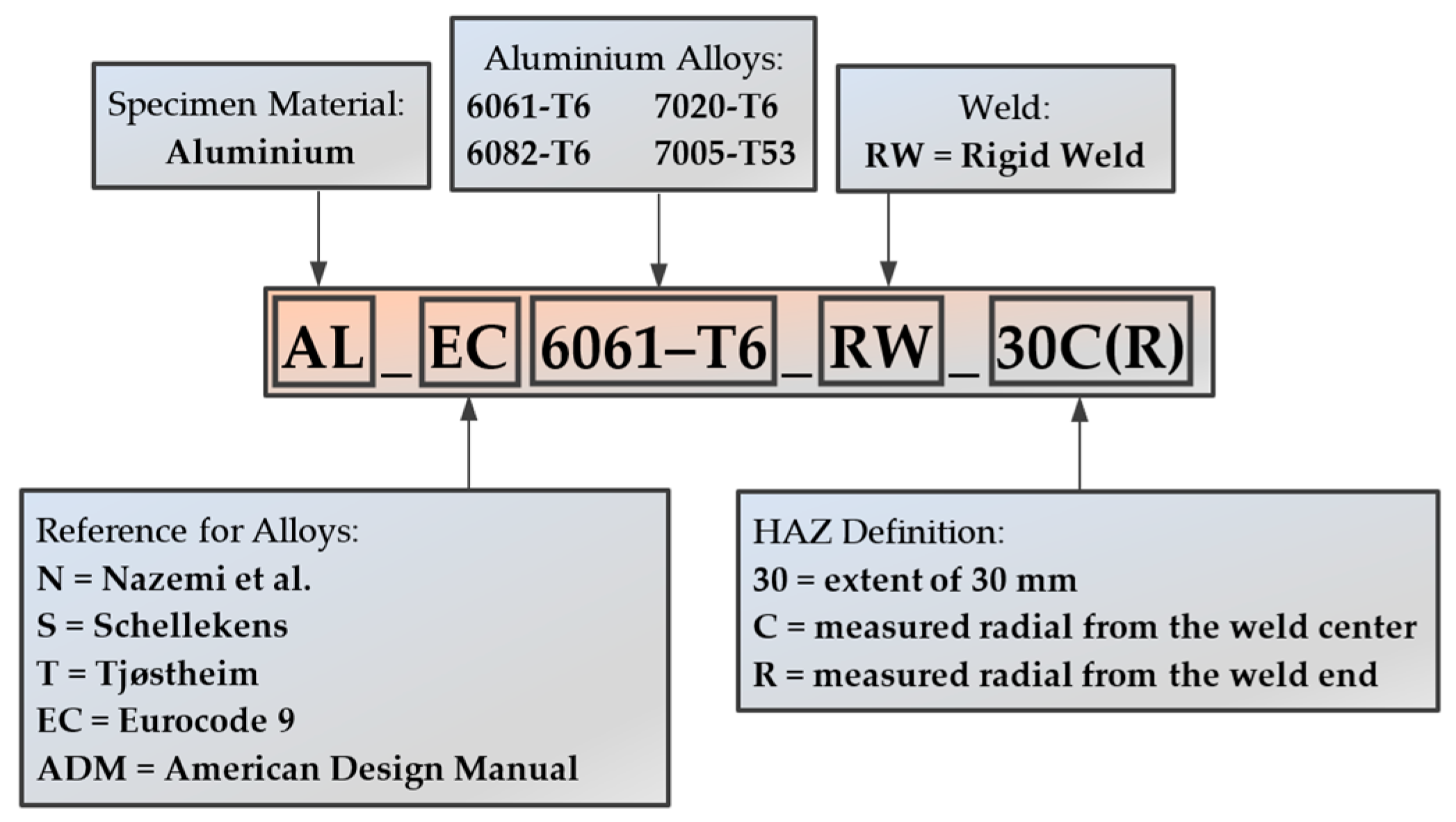
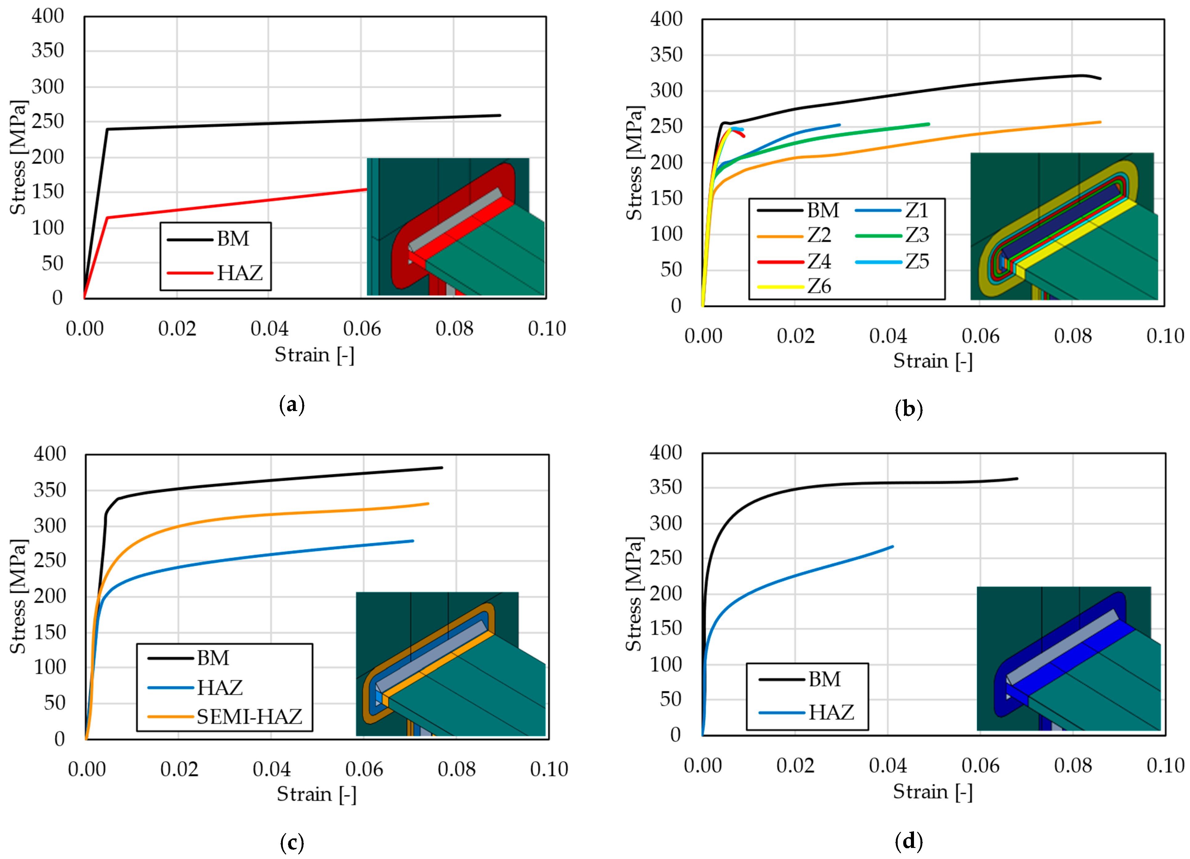
3.1.1. Variation of HAZ Geometry and Mechanical Properties

Since fillet welds were used at the connection between the beam and the column, this led to the occurrence of the HAZ, the area of which had to be appropriately defined. Therefore, various definitions of HAZ were considered, such as the definition according to EC9 [7,9], ADM [28], and previous experimental studies [25,60,61].
Table 3 shows, in addition to the data taken from the standards [7,9,28], the data used for the aluminium alloys and the HAZ from other studies [25,60,61]. Therefore, it is worth mentioning that in [25], specimens with a thickness of 4.8 mm were tested, while in [60] and [61], specimens with thickness of 8 and 10 mm were tested, which is closer to the geometric values of the profiles used in the present test setup. Considering that the thicknesses of the web and flanges of the profiles in this study are between 6 and 10 mm, the required HAZ extent, according to EC9 [7,9] should be set at 30 mm for the thicknesses between 6 and 12 mm. As mentioned in Section 2, the HAZ extent can be reduced to 0.75 bhaz if three valid heat paths are achieved, which ultimately means that the bhaz in this case is 23 mm. In addition to the two observed HAZ extents according to EC9, a third case has been added where an even more conservative situation compared to EC9 is considered, i.e., where the HAZ extent is bhaz + 10 mm (equal to 40 mm).
To represent the behaviour of aluminium alloys, a bilinear stress–strain curve was used in ABAQUS [62] for the EC models. Finally, when using the data for the base material from the experimental studies [25,60,61], the true stress–strain curves (Figure 5) were adopted in the numerical models. Table 3 shows the considered alloys with their mechanical properties. Additionally, Figure 5 shows the different HAZ extents between the EC9 model (AL_EC6061-T6_R30) and the model according to the experimental data (AL_N6061-T6_C25, AL_S6082-T6_C25, AL_6082-T6_C25). Note that colours of the stress–strain curves in Figure 5 correspond to the defined HAZ subzones.

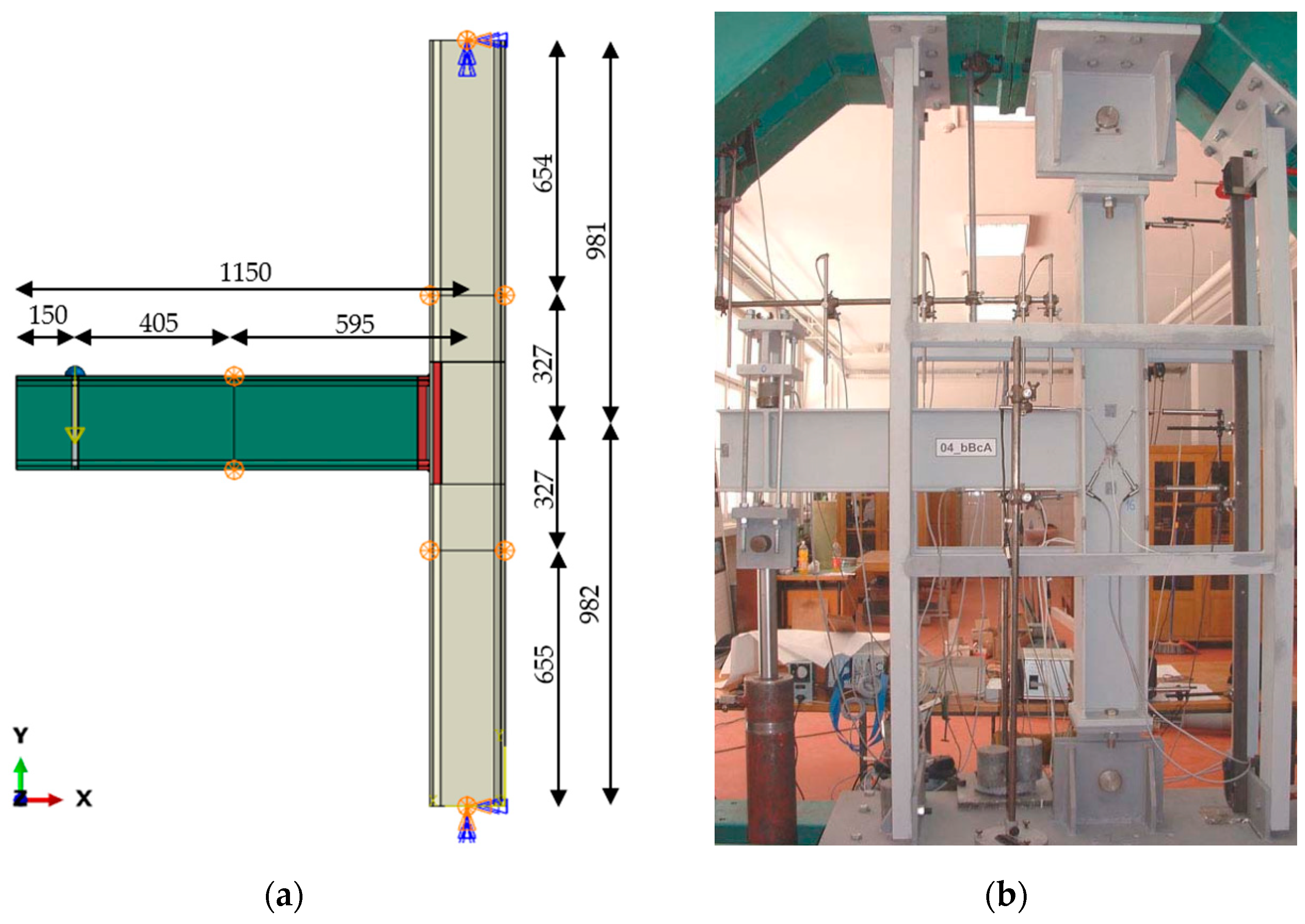
3.1.2. Contacts, Boundary Conditions, and Loading

The contact between the weld and the joint members was modelled with a TIE connection. The end cross-section of the beam is connected to the column flange using a TIE connection as well. Such a contact was defined due to the thin members used, whereas in reality, the preparation of the beam end would be executed, resulting in a full penetration weld.
The test set-up for the numerical analysis (Figure 6a) was chosen in accordance with the experimental programme [27] such that the load is applied to a horizontally placed beam (cantilevered on a vertical column) at a distance of 905 mm from the connection. The column is supported at the bottom where it prevents displacement in all directions and rotation about the X and Y axes. However, unlike the bottom support, the upper support is free to move in the vertical longitudinal direction (Y-direction). Figure 6b shows that the lateral resistance supports are placed at specific points on the column and beam where movement in the Z-direction is prevented. The specimens are loaded with a static force acting on the part of the beam. More specifically, the point of load input is achieved through a semi-circular protrusion welded to the top flange of the beam and located 150 mm from the free end of the beam. The Static Riks solver [62] was used, in which a static force was gradually applied to the test specimens until a final force value of 140 kN was reached.

3.2. Validation of Benchmarked Numerical Model

Considering the lack of experimental studies on welded aluminium beam-to-column joints, the benchmarked numerical model for this study was validated using test results for welded beam-to-column joints made of steel [27]. The geometrical properties of the profiles and the mechanical properties of the steel used for the beam-to-column joint, were adopted in accordance with the experimental data [27]. Therefore, the numerical moment–rotation curves of the steel beam-to-column welded joint were compared with the representative experimental moment–rotation curve in Figure 7. As can be seen in Figure 7, the curve obtained with the numerical model agreed very well with the curve obtained from the experimental data.
With a good agreement of the curve, a good visualisation of the joint failure mode itself can also be observed. In other words, within the obtained results of the steel beam-to-column model (Figure 8), most of the deformation occurred in the column web. More precisely, the column web panel was first deformed due to the effect of shear stress. Subsequently, there was a local buckling of the column web under transversal compression, but also a large local deformation of the tension zone of the column web panel. Furthermore, as expected, the deformation of the flange and web component of the beam in compression was so small that it was practically negligible. Ultimately, this calibrated numerical model was used as a benchmark for the welded aluminium beam-to-column joint numerical models.

4. Results and Discussion
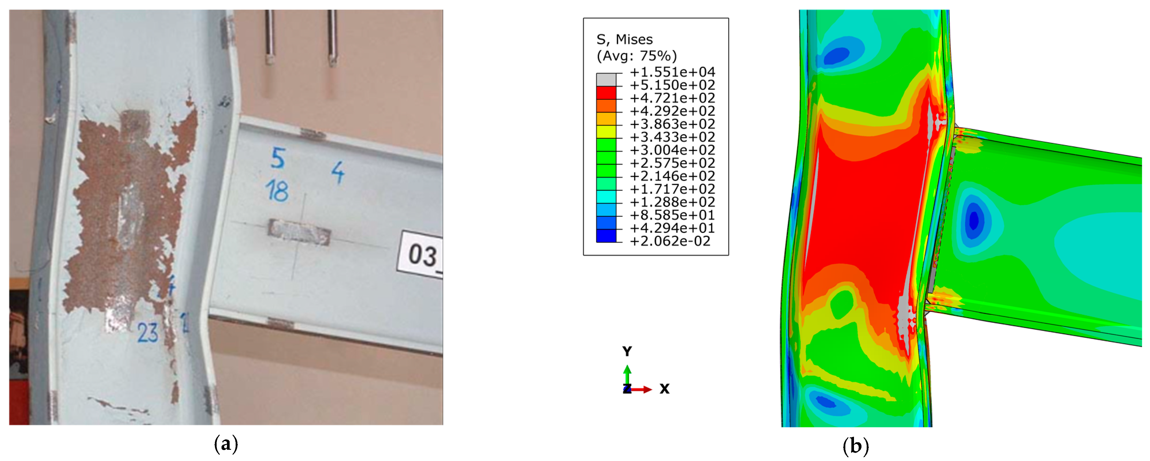
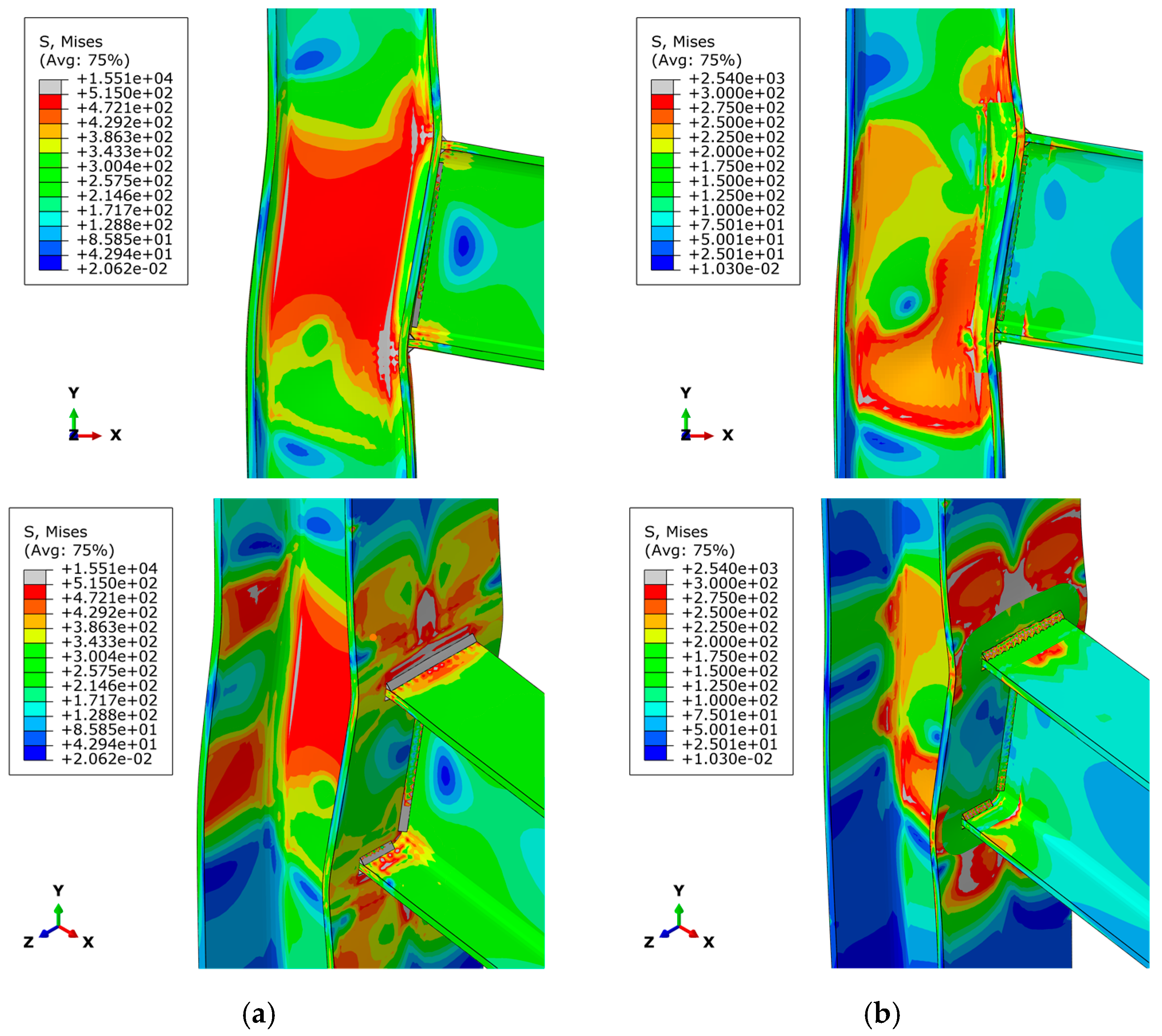
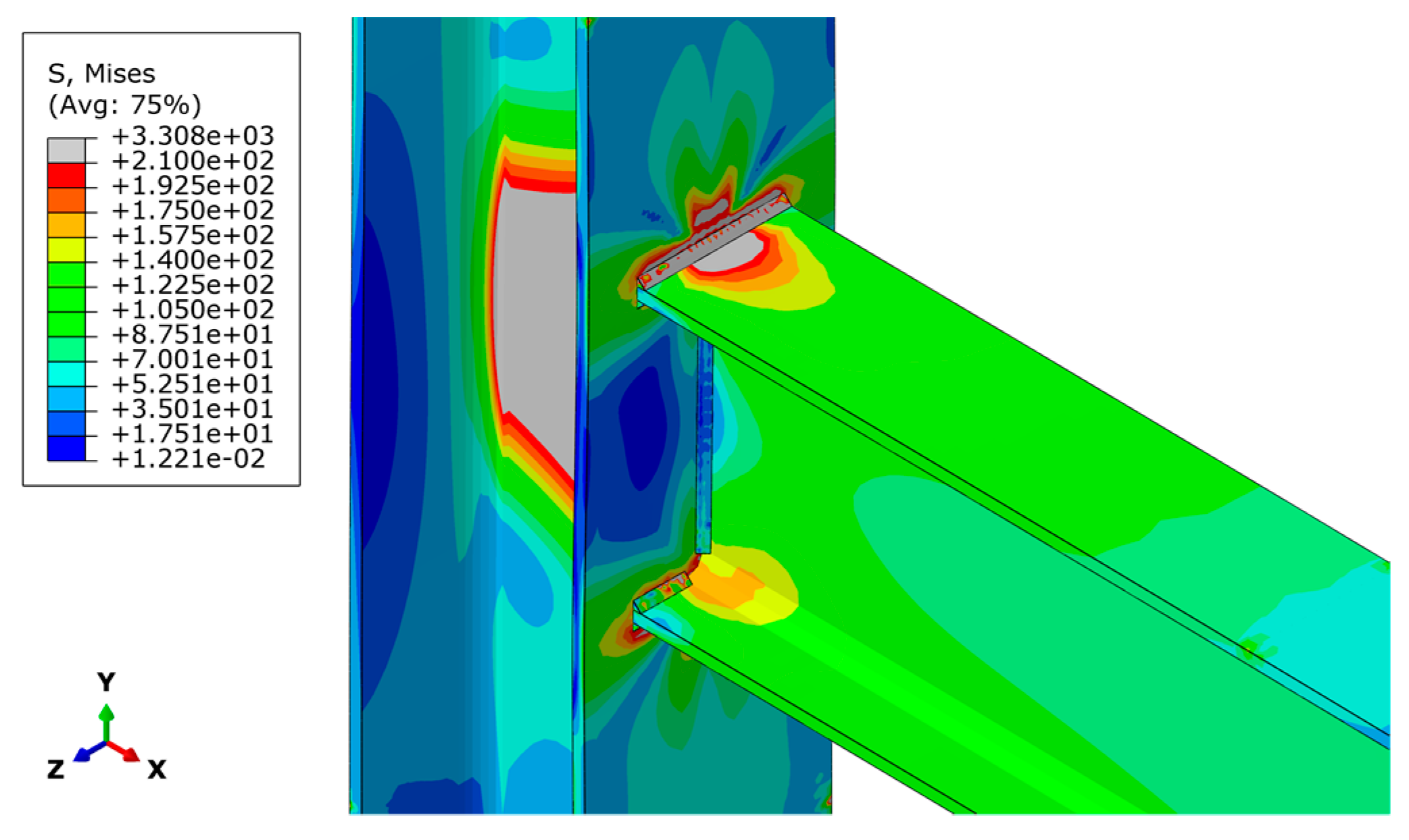
4.1. Failure Modes

A detailed numerical analysis of aluminium beam-to-column joints reveals that most of the deformation did not occur at the column web, as was the case with the steel joint, Figure 9a. In other words, the deformation in the area of the column web panel was significantly lower in the aluminium joint than in the steel joint. Local buckling of the aluminium column web can be considered as an accompanying failure mode. The highest stress concentration occurred at the connection of the top flange aluminium beam with the aluminium column flange, as shown in Figure 9b. This stress concentration led to rapid strain development, resulting in buckling failure of the aluminium column in the HAZ area (flange–web junction), which in turn caused local buckling of the aluminium column web panel. Different assumptions of the HAZ extent, as presented in Figure 5, correspond to the joint mechanical behaviour from Figure 9b in terms of identical failure mode, i.e., local failure at the connection between beam top flange and column flange. Even though in all cases the definition of material degradation in the subzones did not contribute to the change of joint failure mode, it did contribute to the different joint overall behaviour which is visible from moment–rotation curves in Section 4.5.
Although this failure mode is the most common failure mode observed in numerical models of aluminium joints, it is also worth noting that in some models fillet weld failure occurs at the point of highest stress concentration (Figure 10). Such a mode specifically occurs in models where experimental data were used for both the BM and the HAZ (AL_T6082-T6_C25 and AL_S6082-T6_C25), where it is obvious that the BM has better mechanical properties than the weld used for this alloy. However, it should be noted that in some experimental data [60,61], the mechanical properties of the weld are missing, so the assumed weld properties for these models are consistent with EC9 [7,9] for the alloy used.

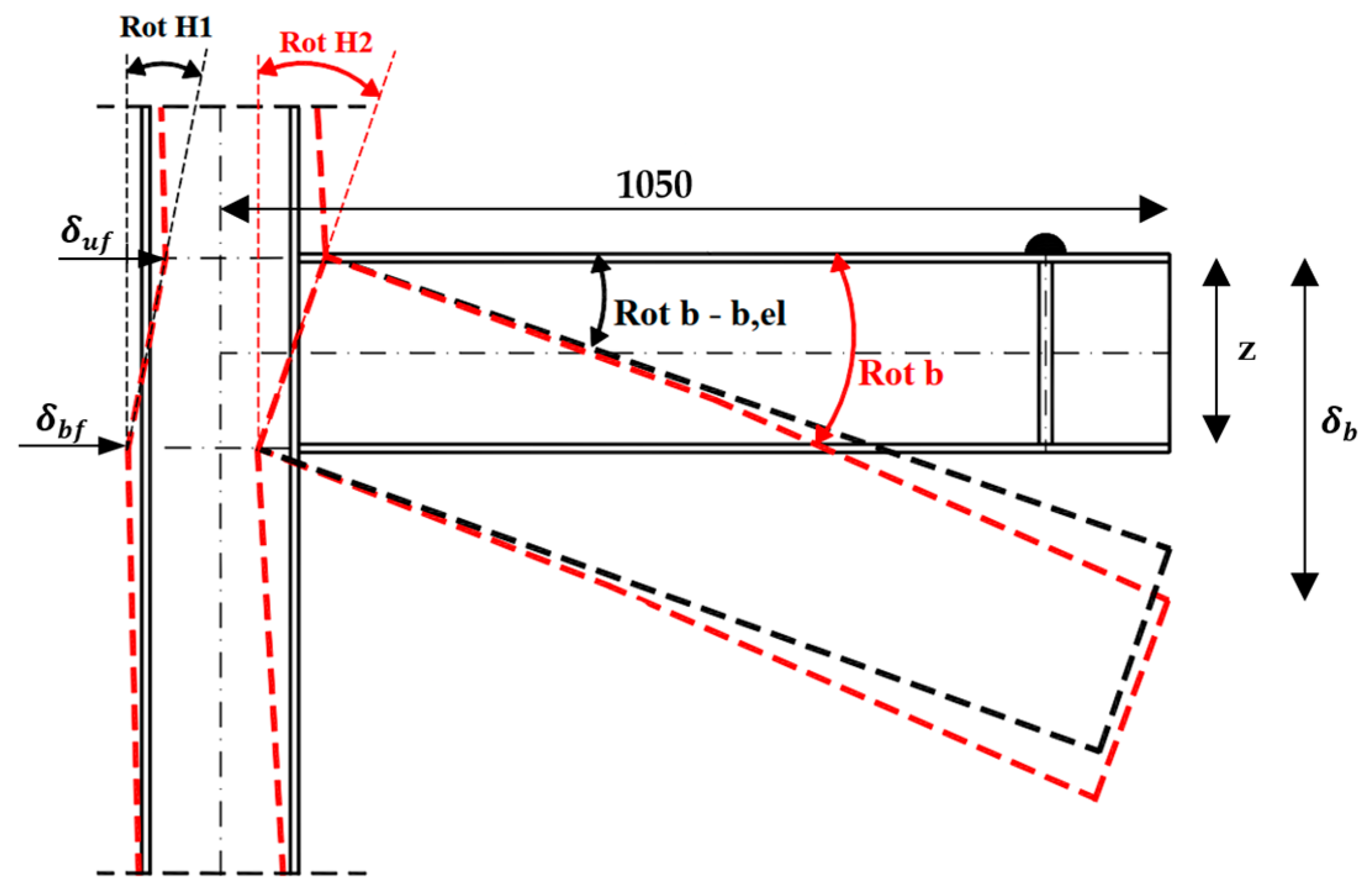
4.2. Moment–Rotation Characterisation

The behaviour of the beam-to-column joint is usually characterised by the moment–rotation curve. Therefore, it was necessary to recalculate all the diagrams as was done in [27]. The bending moment acting on the joint, Mj, corresponds to the applied load, F, multiplied by the distance between the load input point and the outer surface of the column web at which the column is connected to, in this particular case 905 mm:
M j = L f · F = 0.905 · F   [ kNm ]
Finally, in the analysis of the numerical models, both the column and the beam were deformed, so the rotation of the joint is calculated by subtracting the beam elastic rotation and the rotation due to the column web shear deformation from the total rotation of the joint (Figure 11). Therefore, the rotation of the joint can be expressed as follows:
Rot = Rot   b b el Rot   H 1 = arctan δ b 1050 θ b , el δ uf δ bf z
where δ b is the measured displacement at the end of the beam, while θ b , el is the elastic rotation of the beam. The terms δ uf and δ bf are displacements of the column at the level of the beam top and bottom flange, respectively, while ‘z’ is the distance between the centres of gravity of the beam flanges.
A summary of the numerical results obtained by processing the Mj–ϕ curves is shown in Table 4. More specifically, the table contains values such as the maximum bending moment (ultimate resistance) of the joint (Mu), the initial rotational stiffness of the joint (Sj,ini), the rotation at maximum bending moment (ϕMu), and the vertical displacement of the point at the top flange at the end of the beam at maximum bending moment (δMu).

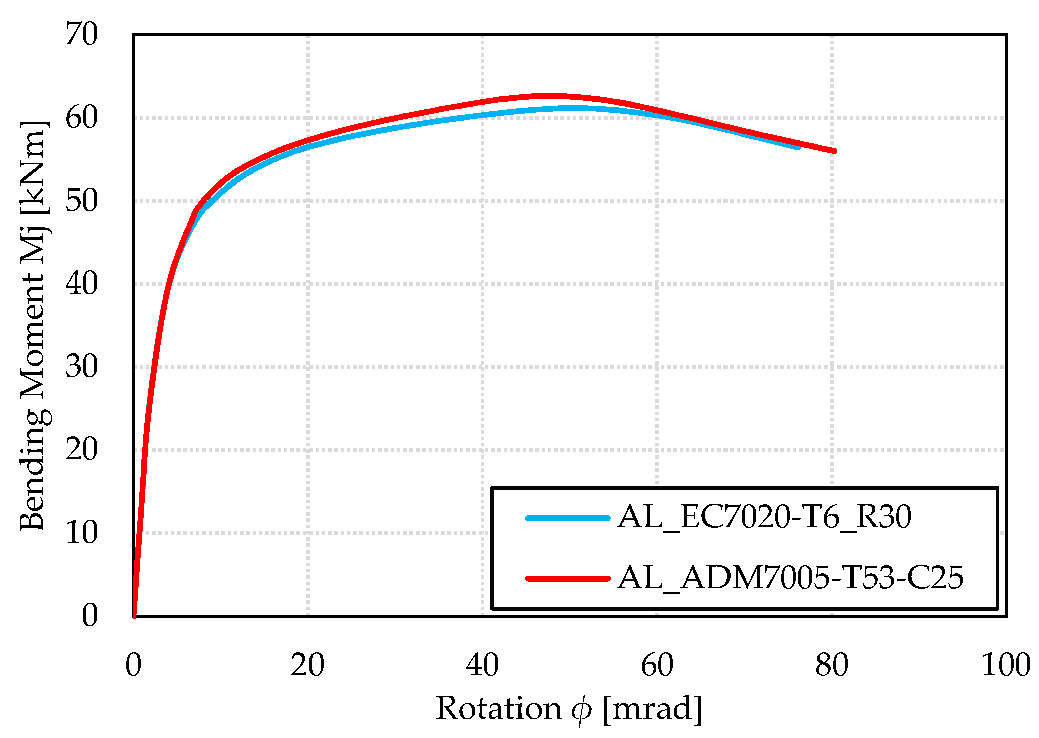
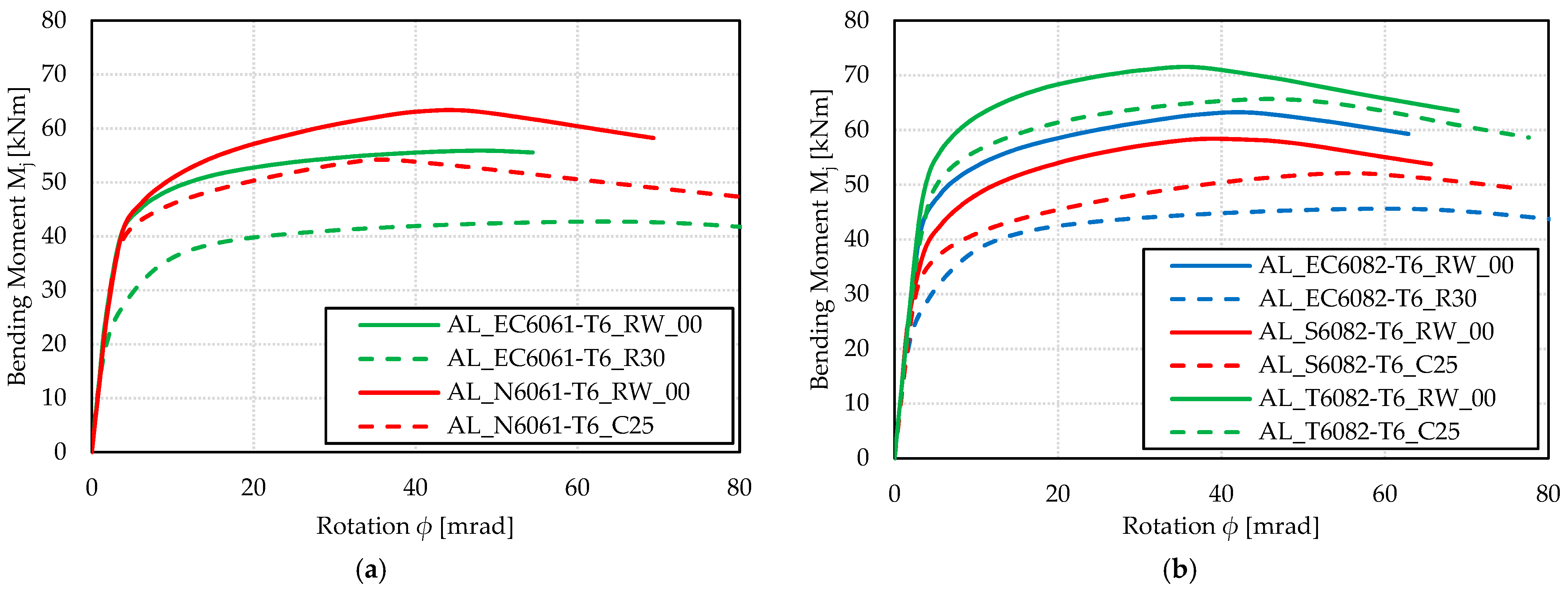
4.3. Effect of Variation of Aluminium Alloys of Base Material

This section presents the results of the beam-to-column joint behaviour regarding the variation of the different aluminium alloys. Therefore, Figure 12a shows the moment–rotation curves for models with nominally the same aluminium alloy EN AW-6061-T6. From Figure 12a and from Table 4, it can be seen that the AL_N6061-T6_C25 model had a better behaviour in terms of resistance by about 27% (54.2/42.7) and 19% (54.2/45.6) compared to the other two models: AL_EC6061-T6_R30 and AL_ADM6061-T6_C25, respectively. These models, however, showed a slightly more ductile behaviour in terms of joint rotation capacity. This behaviour results from the fact that the mechanical properties of the base material as well as the material in the HAZ are more favourable than the mechanical properties of the materials in the other two models. However, when comparing the two remaining models, it was notable that the AL_ADM6061-T6_C25 model achieved a joint ultimate resistance that was approximately 7% higher than the AL_EC6061-T6_R30 model (45.6/42.7), even though the mechanical properties of the materials in the models are very similar. This discrepancy in behaviour results from the different definition of the HAZ extent. There was also an obvious difference between the models in terms of the initial joint rotational stiffness. In other words, the initial stiffness of the AL_N6061-T6_C25 model was about 23% (12.101/9.843) higher compared to the AL_E6061-T6_R30 model.
Figure 12b shows the moment–rotation curves for models with nominally the same alloy EN AW-6082-T6. Comparing the AL_T6082-T6_C25 model with the EC9 model (AL _EC6082-T6_R30), it is clear that the difference between the ultimate bending resistance was about 44% (65.7/45.6), which ultimately shows the conservatism of the EC9 model. Similar results were also obtained in terms of the initial rotational stiffness of the joint. The differences in joint resistances resulted from the fact that different material properties and different HAZ extent are used for each model. However, when it comes to the rotational capacity of the joint at maximum bending moment, the model AL_EC6082-T6_R30 achieved a better rotational capacity by 30% (61/47) compared to the AL_T6082-T6_C25 model and by 7% (61/57) compared to the model AL_S6082-T6_C25. This behaviour can be interpreted by the fact that the models AL _T6082-T6_C25 and AL _S6082-T6_C25 achieved lower rotational capacities than the EC9 model due to the lower elongation of the BM at ultimate tensile strength. Detailed examination of the numerical models also revealed that the same type of failure occurred in all models, i.e., due to the localisation of stresses in the area where the beam flanges are connected to the column, which eventually leads to failure (Figure 9b).
Figure 13 shows the curves for two models containing the alloy EN AW-7xxx-Txx. As can be seen, the alloys differed both in the composition of the alloy itself and in the heat treatment process. Regardless of the differences, it is evident that they have similar mechanical properties in terms of 0.2% proof strength, ultimate tensile strength, and HAZ extent as shown in Table 3. Therefore, the curves for the two observed models matched almost completely.

4.4. Effect of Mechanical Properties Reduction in the HAZ

Figure 14 shows the differences in the resistance and ductility of the model caused by the deterioration of the material properties due to welding. More specifically, the models (AL_EC6061-T6_RW_00 and AL_N6061-T6_RW_00) represent specimens where no material degradation was present, while the remaining models (AL_EC6061-T6_R30 and AL_N6061-T6_C25) from Figure 14a had reduced material properties according to Table 3. From the moment–rotation curves (AL_EC6061-T6_XX), it can be seen that the joint ultimate bending resistance was reduced by about 31% (55.9/42.7) due to the presence of the HAZ, while in the models labelled AL_N6061-T6_XX, there was a reduction in ultimate resistance of about 17% (63.3/54.2). However, in these models, both the BM and the material in the HAZ were based on the experimental data [25], from which it can be concluded that the EC9 models are somewhat more conservative when it comes to the degradation of the material in the HAZ. As for the initial rotational stiffness of the joint, it was found that the model AL_EC6061-T6_RW_00 achieved an initial stiffness about 45% higher (14.364/9.843) than the model with material reduction due to the HAZ (AL_EC6061-T6_R30). However, the ductility of these models was the opposite, i.e., the model AL_EC6061-T6_R30 achieved a higher rotational capacity. Indeed, it can be noted that the curve shape of the AL_EC6061-T6_RW_00 model indicates that there is a possibility of sustained ductile behaviour, as the models have been loaded up to a certain force. Specifically for the AL_N6061-T6_RW_00 and AL_N6061-T6_C25 models, it is visible from Table 4 that the model without material reduction (AL_N6061-T6_RW_00) achieved 28% (46/36) higher ductility, while there were no significant differences in the initial stiffness. The same type of failure was also observed in the detailed examination of the numerical results, i.e., there is a stress concentration at the connection of the beam top flange with the column flange, which eventually leads to failure, accompanied by local buckling of the aluminium column web.
Observing the curves for the models containing alloy EN AW-6082-T6 (Figure 14b), it was concluded that the analogy is the same as for the alloy EN AW-6061-T6 (Figure 14a). Thus, it is obvious that the reduction in ultimate resistance was much more pronounced in the EC9 models than in the models containing material properties determined on the basis of experimental data [25,60,61]. From this, it can be deduced that EC9 is somewhat more conservative in defining the HAZ mechanical properties compared to experimental data.

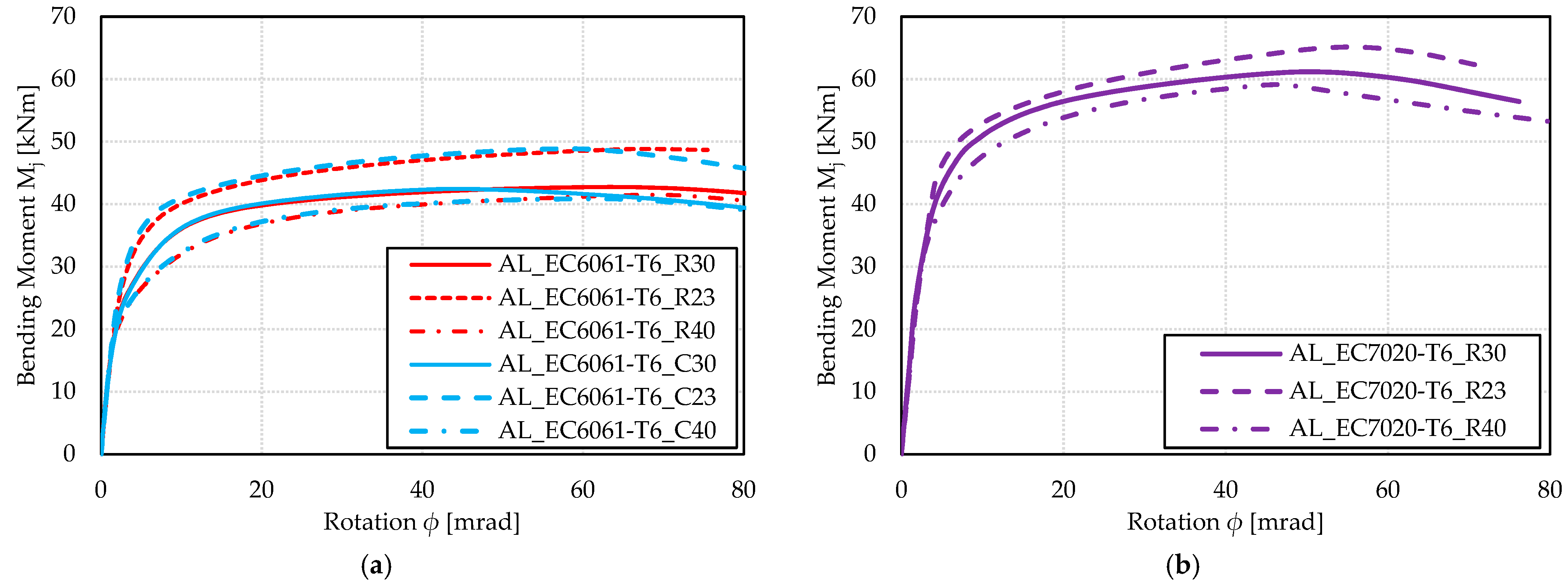
4.5. Effect of Different Definition of the HAZ Extent

As mentioned earlier, models were considered where the extent of the HAZ was measured radially from the end of the weld or from the centre of the weld (Figure 1 and Table 2). Therefore, when considering the joint Mj–ϕ curves for alloy EN AW-6061-T6 (Figure 15a), there was no significant difference in resistance between the two methods of extending the HAZ for the considered model (R vs. C). Namely, if the rotational capacity of the joint was observed, it is evident that models labelled R (AL_EC6061-T6_Rxx) had a slightly better ductility compared to the other models (AL_EC6061-T6_Cxx), by about 11% (69/62), 24% (67/54), or 48% (65/44) depending on the observed models (Table 4). However, considering that the HAZ extent was reduced by 25% due to the achieved three valid heat paths, a 15% (48.8/42.7) higher joint ultimate bending resistance was achieved compared to the nominal extension of the HAZ (bhaz = 30 mm). As mentioned in Section 3.1.1, an even more conservative approach than the EC9 was considered. In other words, the nominal circumference of the HAZ increased by 10 mm, resulting in a slightly reduced resistance of the joint itself by 3% (42.7/41.5). The above analogy also applies to the alloy EN AW-7020-T6 alloy, as shown in Figure 15b.

5. Conclusions

A comprehensive numerical study was carried out on 21 models of aluminium beam-to-column welded joints. Laboratory tests of steel beam-to-column joints were used as a benchmark for the numerical simulations of aluminium joints. Several parameters were varied to obtain the results necessary to gain better insight into the behaviour of welded aluminium structural joints under the influence of the HAZ. In addition to the specifications given in European and American standards for the design of aluminium structures, experimental data from recent literature on HAZ were also used as input for numerical models. The following conclusions can be drawn from the obtained numerical results:
(1)
Compared to the benchmark steel beam-to-column joint, the aluminium beam-to-column joint showed significant differences in overall behaviour and failure mode. In the aluminium models, the joint failure occurred at the connection of the top flange aluminium beam with the aluminium column flange, while the steel joint failed in the column web zone. It is precisely the significant effect of the HAZ that led to the formation of the highest stress concentration and consequently to the local failure of the connection.
(2)
The degradation of the material properties in the HAZ significantly reduced the bending resistance of the joint. Based on the EC numerical models (RW_00 vs. R30) for the 6xxx series alloys (6061-T6 and 6082-T6), a decrease of 31% and 39%, respectively, was observed in ultimate bending resistance. On the other hand, more realistic models with HAZ defined and labelled N, S, and T had much smaller drops in ultimate bending resistance (17%, 12%, and 6%, respectively) compared to their identical models without reduced mechanical properties.
(3)
The validity of the HAZ extent should also be re-investigated. A model with a smaller HAZ extent (AL_EC6061-T6_R23) compared to model with a higher HAZ extent (AL _EC6061-T6_R30) showed a more favourable behaviour in both ultimate bending moment resistance and the initial stiffness of the joint.
(4)
It appears that a more precisely (gradual) defined degradation of material properties in the HAZ, i.e., in several subzones, ultimately led to a more favourable behaviour of the beam-to-column joint compared to the model where the degradation of the material occurred uniformly over the entire HAZ extent according to the standards. Therefore, the optimal assumption of the HAZ definition should be taken as the one from model labelled N, where the gradual degradation is defined based on experimental studies. Such a HAZ definition led to higher bending resistance and initial stiffness of the beam-to-column joint.
(5)
There was no significant influence of the HAZ extent definition (C or R) for the considered thicknesses of the welded members. However, this assumption of HAZ measurement can significantly influence the behaviour of specimens where thicker elements (20 mm and more) are welded together.
Future research on this topic should be based on the development and application of new (improved) welding processes (DP-MIG, AC-MIG, etc.) that can achieve a smaller reduction within the HAZ. The effects of these welding processes on the HAZ should first be investigated experimentally. Finally, it should be noted that the reduced mechanical properties of aluminium alloys in the HAZ need to be statistically evaluated in order to provide a database for the reliable design of welded aluminium structures.

Author Contributions

Conceptualisation, D.S.; methodology, all authors; software, V.Ž.; validation, D.S. and V.Ž.; formal analysis, V.Ž. and A.V.; investigation, V.Ž. and A.V.; resources, all authors.; data curation, all authors; writing—original draft preparation, V.Ž. and A.V.; writing—review and editing, D.S.; visualization, all authors; supervision, D.S. All authors have read and agreed to the published version of the manuscript.

Funding

This research received no external funding.

Institutional Review Board Statement

Not applicable.

Informed Consent Statement

Not applicable.

Data Availability Statement

The data presented in this study are available on request from the corresponding author.

Conflicts of Interest

The authors declare no conflict of interest.

Abbreviations

List of Symbols and Abbreviations
EC 9Eurocode 9
EC 3Eurocode 3
HAZHeat-Affected Zone
ADMAmerican Design Manual
CSACanadian Standard Association
MIGMetal Inert Gas
TIGTungsten Inert Gas
FSWFriction Stir Welding
LWLaser Welding
CMTCold Metal Transfer
DP-MIGDouble Pulse-MIG
AC-MIGAlternating Current-MIG
GMAWGas Metal Arc Welding
LBWLaser Beam Welding
BMBase Material
HVHardness in Vickers
HRFHardness in Rockwell
DICDigital Image Correlation
VFMVirtual Fields Method
fo0.2% proof strength
fuultimate strength
fo,haz0.2% proof strength in the HAZ
fu,hazultimate strength in the HAZ
α2factor that considers influence of temperature above 80 °C
ρo,hazreduction factor of 0.2% proof strength in the HAZ
ρu,hazreduction factor of ultimate strength in the HAZ
fwcharacteristic strength of weld metal
εucharacteristic value of elongation at rupture
EYoung’s modulus of elasticity
Mjbending moment
Fapplied force/load
Lflever arm from the applied force to the connection of the beam and column
δufdisplacement of the column at beam top flange level
δbfdisplacement of the column at beam bottom flange level
δbmeasured displacement at the end of the beam
θb,elelastic rotation of the beam
zdistance between the centres of gravity of the beam flanges
ϕjoint rotation
Mujoint ultimate resistance
Sj,iniinitial rotational stiffness
ϕMurotation at maximum bending moment
δMuvertical displacement of the point at the top flange at the end of the beam at maximum bending moment

References

  1. Mazzolani, F.M. 3D aluminium structures. Thin Walled Struct. 2012, 61, 258–266. [Google Scholar] [CrossRef]
  2. Dokšanović, T.; Džeba, I.; Markulak, D. Applications of aluminium alloys in civil engineering. Tech. Gaz. 2017, 24, 1609–1618. [Google Scholar] [CrossRef]
  3. Skejić, D.; Boko, I.; Torić, N. Aluminium as a material for modern structures. Građevinar 2015, 67, 1075–1085. [Google Scholar] [CrossRef] [Green Version]
  4. Kosteas, D. Sustainability, Durability and Structural Advantages as Leverage in Promoting Aluminium Structures. Key Eng. Mater. 2016, 710, 13–21. [Google Scholar] [CrossRef]
  5. Radlbeck, C.; Dienes, E.; Kosteas, D. Sustainability of Aluminium in Buildings. Struct. Eng. Int. 2004, 14, 221–224. [Google Scholar] [CrossRef]
  6. Efthymiou, E.; Cöcen, Ö.N.; Ermolli, S.R. Sustainable Aluminium Systems. Sustainability 2010, 2, 3100–3109. [Google Scholar] [CrossRef] [Green Version]
  7. EN 1999; Eurocode 9: Design of Aluminium Structures. European Committee for Standardisation (CEN): Brussels, Belgium, 2007.
  8. EN 1993; Eurocode 3: Design of Steel Structures. European Committee for Standardisation (CEN): Brussels, Belgium, 2007.
  9. FprEN 1999; Eurocode 9: Design of Aluminium Structures. European Committee for Standardisation (CEN): Brussels, Belgium, 2022.
  10. Skejić, D.; Valčić, A.; Čudina, I. Optimisation of Aluminium Halls in the Republic of Croatia. Tech. Gaz. 2022, 29, 1454–1463. [Google Scholar] [CrossRef]
  11. Skejić, D.; Čudina, I.; Garašić, I.; Mazzolani, F.M. Behaviour of Steel Tubular Knee Joint in Aluminium Frames with Tension-Tie Element. Appl. Sci. 2021, 11, 70. [Google Scholar] [CrossRef]
  12. Skejić, D.; Ćurković, I.; Garašić, I.; Čudina, I.; Dokšanović, T. Behaviour of Steel Tube Knee Joint Inserts used in Aluminium Portal Frames. ce/papers 2021, 4, 174–181. [Google Scholar] [CrossRef]
  13. Skejić, D.; Orehovec, D.; Ćurković, I. Prefabricated aluminium halls. Građevinar 2021, 73, 141–151. [Google Scholar] [CrossRef]
  14. De Matteis, G.; Mandara, A.; Mazzolani, F.M. T-stub aluminium joints: Influence of behavioural parameters. Comput. Struct. 2000, 78, 311–327. [Google Scholar] [CrossRef]
  15. Xu, H.; Guo, X.; Luo, Y. The Load-Bearing Capacity of Aluminium Alloy T-stub Joints. Adv. Mater. Res. 2011, 261–263, 765–769. [Google Scholar] [CrossRef]
  16. De Matteis, G.; Naqash, M.T.; Brando, G. Effective length of aluminium T-stub connections by parametric analysis. Eng. Struct. 2012, 41, 548–561. [Google Scholar] [CrossRef]
  17. Naqash, M.T.; Brando, G.; De Matteis, G. Calibration and Validation of Numerical Models through Experimental Tests. Int. J. Adv. Struct. Geotech. Eng. 2014, 3, 80–90. [Google Scholar]
  18. Maljaars, J.; De Matteis, G. Structural Response of Aluminium T-Stub Connections at Elevated Temperatures and Fire. Key Eng. Mater. 2016, 710, 127–136. [Google Scholar] [CrossRef]
  19. De Matteis, G.; Brando, G. Analysis of Aluminium Beam-to-Column Joints by the Component Method: Existing Studies and Research Needs. Key Eng. Mater. 2016, 710, 409–414. [Google Scholar] [CrossRef]
  20. De Matteis, G.; Brescia, M.; Formisano, A.; Mazzolani, F.M. Behaviour of welded aluminium T-stub joints under monotonic loading. Comput. Struct. 2009, 87, 990–1002. [Google Scholar] [CrossRef]
  21. Zhongxing, W.; Yuanqing, W.; Xiang, Y.; Ying, Z.; Zhiqiang, L.; Zongyi, W. Numerical modelling of extruded aluminium alloy T-stubs connected by swage-locking pins: FE validation and parametric study. Thin Walled Struct. 2020, 155, 106926. [Google Scholar] [CrossRef]
  22. Zhongxing, W.; Yuanqing, W.; Ying, Z.; Gardner, L.; Yuanwen, O. Experimental investigation and design of extruded aluminium alloy T-stubs connected by swage-locking pins. Eng. Struct. 2019, 200, 109675. [Google Scholar] [CrossRef]
  23. Zhongxing, W.; Yuanqing, W.; Ying, Z.; Zongyi, W.; Yuanwen, O. Experimental investigation on the behaviour of aluminium alloy beam-to-column joints connected by swage-locking pins. Eng. Struct. 2020, 213, 110578. [Google Scholar] [CrossRef]
  24. Zhongxing, W.; Yuanqing, W.; Beibei, L.; Ying, Z. Experimental and numerical study on seismic behaviour of aluminium alloy frames. J. Build. Eng. 2022, 50, 104231. [Google Scholar] [CrossRef]
  25. Nazemi, N.; Ghrib, F. Strength Characteristics of Heat-Affected Zones in Welded Aluminum Connections. J. Eng. Mech. 2019, 145, 04019103. [Google Scholar] [CrossRef]
  26. Cheng, J.; Song, G.; Zhang, X.; Liu, C.; Liu, L. Review of Techniques for Improvement of Softening Behavior of Age-Hardening Aluminum Alloy Welded Joints. Materials 2021, 14, 5804. [Google Scholar] [CrossRef] [PubMed]
  27. Skejić, D. Reliability of Welded Semi-Rigid Beam to Column Joints. Master’s Thesis, University of Zagreb, Faculty of Civil Engineering, Zagreb, Croatia, 2005. [Google Scholar]
  28. Aluminum Association. Aluminum Design Manual; Aluminum Association: Washington, DC, USA, 2005. [Google Scholar]
  29. Boko, I.; Skejić, D.; Torić, N. Aluminium Structures. In Textbook at University of Split and textbook at University of Zagreb; University of Split, Faculty of Civil Engineering, Architecture and Geodesy: Split, Croatia, 2017. [Google Scholar]
  30. CSA-W59.2-M1991 (R2013); Welded Aluminum Construction. CSA (Canadian Standard Association): Rexdale, ON, Canada, 2013.
  31. CSA-S157-05/S157.1-05 (R2010); Strength Design in Aluminum. CSA (Canadian Standard Association): Rexdale, ON, Canada, 2015.
  32. Soetens, F. Welded connections in aluminium alloy structures. Heron 1987, 32, 1–48. [Google Scholar]
  33. Matusiak, M. Strength and Ductility of Welded Structures in Aluminium Alloys. Ph.D. Thesis, Norwegian University of Science and Technology, Trondheim, Norway, 1999. [Google Scholar]
  34. ECCS. European Recommendations for Aluminium Alloy Structures, 1st ed. European Convention for Constructional Steelwork (ECCS), Technical Committee 2—Aluminium Alloy Structures. 1978. Available online: www.eccspublications.eu (accessed on 11 January 2023).
  35. NEN 3854:1983; Technical Principles for the Design of Building Structures, Aluminium Structures. Royal Netherlands Standardization Institute: Delft, The Netherlands, 1983.
  36. CP 118:1969; The Structural Use of Aluminium. British Standard Code of Practice: London, UK, 1969; (replaced by BS 8118).
  37. Wang, T.; Hopperstad, O.S.; Lademo, O.-G.; Larsen, P.K. Finite element analysis of welded beam-to-column joints in aluminium alloy EN AW 6082 T6. Finite Elem. Anal. Des. 2007, 44, 1–16. [Google Scholar] [CrossRef]
  38. Dørum, C.; Lademo, O.-G.; Myhr, O.R.; Berstad, T.; Hopperstad, O.S. Finite element analysis of plastic failure in heat-affected zone of welded aluminium connections. Comput. Struct. 2010, 88, 519–528. [Google Scholar] [CrossRef]
  39. Zhang, Z.L.; Ødegard, J.; Myhr, O.R.; Fjaer, H. From microstructure to deformation and fracture behaviour of aluminium welded joints—A holistic modelling approach. Comput. Mater. Sci. 2001, 21, 429–435. [Google Scholar] [CrossRef]
  40. Moen, L.A.; Hopperstad, O.S.; Langseth, M. Rotational capacity of aluminium beams under moment gradient. I: Experiments. J. Struct. Eng. 1999, 125, 910–920. [Google Scholar] [CrossRef]
  41. Sato, Y.S.; Kokawa, H.; Enomoto, M.; Jogan, S. Microstructural Evolution of 6063 Aluminum during Friction-Stir Welding. Metall. Mater. Trans. A: Phys. Metall. Mater. Sci. 1999, 30, 2429–2437. [Google Scholar] [CrossRef]
  42. Missori, S.; Sili, A. Mechanical behaviour of 6082-T6 aluminium alloy welds. Metall. Sci. Technol. 2000, 18, 12–18. [Google Scholar]
  43. Wang, T. Modelling of Welded Thin-Walled Aluminium Structures. Ph.D. Thesis, Norwegian University of Science and Technology, Trondheim, Norway, 2006. [Google Scholar]
  44. Zheng, L.; Petry, D.; Rapp, H.; Wierzbicki, T. Characterization of material and fracture of AA6061 butt weld. Thin Walled Struct. 2009, 47, 431–441. [Google Scholar] [CrossRef]
  45. Li, J.B.; Zhang, Q.L.; Ding, J.M. Experiments on Properties of Aluminium Welding Joints. Struct. Eng. Int. 2006, 16, 331–338. [Google Scholar] [CrossRef]
  46. Sukawet, S.; Muangjunburee, P. Microstructure and Mechanical Properties of Welding repair of 5083 Aluminium alloy. Key Eng. Mater. 2015, 658, 151–155. [Google Scholar] [CrossRef]
  47. Baskutis, S.; Baskutiene, J.; Bernotaitis, E. Experimental Study of Welded Joints of Aluminium Alloy AW6082. Solid State Phenom. 2017, 260, 212–218. [Google Scholar] [CrossRef]
  48. Guzmán, I.; Granda, E.; Acevedo, J.; Martínez, A.; Dávila, Y.; Velázquez, R. Comparative in Mechanical Behavior of 6061 Aluminium Alloy Welded by Pulsed GMAW with Different Filler Metals and Heat Treatments. Materials 2019, 12, 4157. [Google Scholar] [CrossRef] [Green Version]
  49. Yang, C.; Ni, D.R.; Xue, P.; Xiao, B.L.; Wang, W.; Wang, K.S.; Ma, Z.Y. A comparative research on bobbin tool and conventional friction stir welding of Al-Mg-Si alloy plates. Mater. Charact. 2018, 145, 20–28. [Google Scholar] [CrossRef]
  50. Wang, O.; Chen, H.; Zhu, Z.; Qiu, P.; Cui, Y. A characterization of microstructure and mechanical properties of A6N01S-T5 aluminum alloy hybrid fiber laser-MIG welded joint. Int. J. Adv. Manuf. Technol. 2016, 86, 1375–1384. [Google Scholar] [CrossRef]
  51. Yan, S.; Chen, H.; Zhu, Z.; Gou, G. Hybrid laser-Metal Inert Gas welding of Al-Mg-Si Alloy joints: Microstructure and Mechanical Properties. Mater. Des. 2014, 61, 160–167. [Google Scholar] [CrossRef]
  52. Wang, L.; Gao, M.; Zhang, C.; Zeng, X. Effect of beam oscillating pattern on weld characterization of laser welding of AA6061-T6 aluminum alloy. Mater. Des. 2016, 108, 707–717. [Google Scholar] [CrossRef]
  53. Yi, J.; Cao, S.F.; Li, L.X.; Guo, P.C.; Liu, K.Y. Effect of welding current on morphology and microstructure of Al alloy T-joint in double-pulsed MIG welding. Trans. Nonferrous Met. Soc. China 2015, 25, 3204–3211. [Google Scholar] [CrossRef]
  54. Nie, F.; Dong, H.; Chen, S.; Li, P.; Wang, L.; Zhao, Z.; Li, X.; Zhang, H. Microstructure and Mechanical Properties of Pulse MIG Welded 6061/A356 Aluminum Alloy Dissimilar Butt Joints. J. Mater. Sci. Technol. 2018, 34, 551–560. [Google Scholar] [CrossRef]
  55. Peng, X.; Cao, X.; Xu, G.; Deng, Y.; Tang, L.; Yin, Z. Mechanical Properties, Corrosion Behavior, and Microstructures of a MIG-Welded 7020 Al Alloy. J. Mater. Eng. Perform. 2016, 25, 1028–1040. [Google Scholar] [CrossRef]
  56. Guo, Y.; Pan, H.; Ren, L.; Quan, G. An investigation on plasma-MIG hybrid welding of 5083 aluminum alloy. Int. J. Adv. Manuf. Technol. 2018, 98, 1433–1440. [Google Scholar] [CrossRef]
  57. Baskutis, S.; Žunda, A.; Kreivaitis, R. Mechanical properties and microstructure of aluminium alloy AW6082-T6 joints welded by double-sided MIG process before and after aging. Mechanika 2019, 25, 107–113. [Google Scholar] [CrossRef]
  58. Yang, K.; Wang, F.; Liu, H.; Wang, P.; Luo, C.; Yu, Z.; Yang, L.; Li, H. Double-Pulse Triple-Wire MIG Welding of 6082-T6 Aluminum Alloy: Process Characteristics and Joint Performances. Metals 2021, 11, 1388. [Google Scholar] [CrossRef]
  59. Hoang, N.H.; Morin, D.; Langseth, M. Testing and modelling of butt-welded connections in thin-walled aluminium structures. Thin-Walled Struct. 2022, 171, 108681. [Google Scholar] [CrossRef]
  60. Schellekens, T. Ductility Analysis of Aluminum Alloy Connections. Master’s Thesis, Eindhoven University of Technology, Eindhoven, The Netherlands, 2020. [Google Scholar]
  61. Lundberg, S.; Tjøstheim, N.J. Mechanical Properties in Heat Affected Zone of Welded EN AW 6082 T6. Internal Report, 2014. [Google Scholar]
  62. Dassault Systèmes Simulia Corp. ABAQUS 2021, User’s Manual; Dassault Systèmes Simulia Corp.: Providence, RI, USA, 2021. [Google Scholar]
Figure 1. Extent of HAZ according to EC9 [7,9].
Buildings 13 00718 g001
Figure 2. HAZ subzones: (a) subzones on the specimen, (b) hardness curve of the welded specimen [25].
Buildings 13 00718 g002
Figure 3. Nomenclature system of specimens; Nazemi et al. [25], Schellekens [60], Tjøstheim [61], Eurocode 9 [7,9], American Design Manual [28].
Buildings 13 00718 g003
Figure 4. Discretisation of numerical model: (a) sensitivity to different finite element sizes; (b) optimal mesh.
Buildings 13 00718 g004
Figure 5. Stress–strain behaviour for numerical models: (a) AL_EC6061-T6_R30; (b) AL_N6061-T6_xx; (c) AL_S6082-T6_xx; (d) AL_T6082-T6_xx.
Buildings 13 00718 g005
Figure 6. Welded beam-to-column joint set-up: (a) Numerical model (axial dimensions, units in mm); (b) Experimental set-up [27].
Buildings 13 00718 g006
Figure 7. Experimental and FEM moment–rotation curve for steel beam-to-column joint.
Buildings 13 00718 g007
Figure 8. Failure mode of steel beam-to-column welded joint: (a) experimental [27], (b) numerical.
Buildings 13 00718 g008
Figure 9. Failure modes of the beam-to-column joint at maximum force: (a) steel; (b) aluminium (AL_EC6061-T6_RW_R30).
Buildings 13 00718 g009
Figure 10. Failure of the weld for the aluminium beam-to-column joint (AL_T6082-T6_C25).
Buildings 13 00718 g010
Figure 11. Rotation components of the joint for the determination of connection rotation [27].
Buildings 13 00718 g011
Figure 12. Moment–rotation curves for models with aluminium alloys: (a) EN AW-6061-T6; (b) EN AW-6082-T6.
Buildings 13 00718 g012
Figure 13. Moment–rotation curves for models with aluminium alloys EN AW-7xxx-Txx.
Buildings 13 00718 g013
Figure 14. Moment–rotation curves for models with the effect of reduced mechanical properties in the HAZ for alloys: (a) EN AW-6061-T6; (b) EN AW-6082-T6.
Buildings 13 00718 g014
Figure 15. Moment–rotation curves for models with the effect of different assumption of the HAZ extent for alloys: (a) EN AW-6061-T6; (b) EN AW-7020-T6.
Buildings 13 00718 g015
Table 1. Overview of the studies on the HAZ extent and ultimate strength.
Ref.Welding MethodWeld TypeAlloyThickness [mm]HAZ Extent from Centre [mm]Ultimate Strength of the Joint [MPa]Joint Efficiency = Joint/BM [%]Distance of Min. Hardness from Centre [mm]Min. Hardness/Base Hardness [%]
Moen et al. (1999) [40]MIGwelded stiffenerEN AW-6082-T65.030.021366.012.063.0
Sato et al. (1999) [41]FSWbutt weldEN AW-6063-T56.015.0--10.065.0
Missori et al. (2000) [42]MIGbutt weldEN AW-6082-T610.020.016962.010.055.0
Wang (2006) [43]MIGfillet weldEN AW-6082-T65.030.027076.010.065.0
Zheng et al. (2009) [44]MIGbutt weldEN AW-6061-T63.023.018176.010.050.0
Li et al. (2006) [45]TIGbutt weldEN AW-6061-T66.025.018356.010.050.0
Sukawet et al. (2015) [46]GMAWbutt weldEN AW-50836.04.019365.03.092.0
Baskutis et al. (2017) [47]GMAWbutt weldEN AW-6082-T610.010.018369.05.086.0
Guzman et al. (2019) [48]Pulsed
GMAW
butt weldEN AW-6061-T47.017.5153-14.595
Yang et al. (2018) [49]FSWbutt weldEN AW-6061-T46.3512.522993.08.075.0
Wang et al. (2016) [50]MIGbutt weld6N01S-T58.022.021072.012.058.0
Laser-MIG24.024383.014.060.0
Yan et al. (2014) [51]MIGbutt weldEN AW-6005-T65.017.019068.88.087.0
Laser-MIG12.020674.67.084.0
Wang et al. (2016) [52]LBWbutt weldEN AW-6061-T64.05.0220–231~70.01.075.0
Table 2. Summary of analysed numerical models.
Model NameAluminium AlloyExtent of HAZ
bhaz [mm]Measured
AL_EC6061-T6_RW_00EC6061-T6 [7,9]--
AL_EC6061-T6_RW_R3030radial from the weld end
AL_EC6061-T6_R3030
AL_EC6061-T6_R2323
AL_EC6061-T6_R4040
AL_EC6061-T6_C3030radial from the weld centreline
AL_EC6061-T6_C2323
AL_EC6061-T6_C3040
AL_EC7020-T6_R30EC7020-T6 [7,9]30radial from the weld end
AL_EC7020-T6_R2323
AL_EC7020-T6_R4040
AL_EC6082-T6_RW_00EC6082-T6 [7,9]--
AL_EC6082-T6_R3030radial from the weld end
AL_ADM7005-T53_C25ADM7005-T53 [28]25radial from the weld centreline
AL_ADM6061-T6_C25ADM6061-T6 [28]25
AL_N6061-T6_C25N6061-T6 [25]25radial from the weld centreline
AL_N6061-T6_RW_00-
AL_S6082-T6_C25S6082-T6 [60]15radial from the weld end
AL_S6082-T6_RW_00-
AL_T6082-T6_C25T6082-T6 [61]25radial from the weld end
AL_T6082-T6_RW_00-
Note: Mechanical properties of aluminium alloys are shown in Table 3.
Table 3. Mechanical properties of aluminium alloys.
Aluminium Alloyfo
[MPa]
fu
[MPa]
fo,haz
[MPa]
fu,haz
[MPa]
ρo,hazρu,hazfw
[MPa]
εu
[%]
E
[MPa]
EC6061-T62402601151750.480.67190970,000
EC6082-T62603101251860.480.6021010
EC7020-T62903502052800.710.8026010
ADM7005-T533053451652750.540.802401072,400
ADM6061-T62402601051650.440.64190969,600
N6061-T62502951 Value of zone
Z1-Z6
--1 Value of Z1868,900
S6082-T6334353207
271
261
307
0.620.74210873,000
T6082-T63163401772560.560.75210770,000
1 Z1–Z6 represent zones of heat affected material from experimental data [25] (Figure 5).
Table 4. Numerical results for joint ultimate resistance, initial stiffness, and ductility.
Model NameMu
[kNm]
Sj,ini
[kNm/mrad]
ϕMu
[mrad]
δMu
[mm]
AL_EC6061-T6_RW_0055.914.36450154
AL_EC6061-T6_RW_R3045.610.08963126
AL_EC6061-T6_R3042.79.84365120
AL_EC6061-T6_R2348.811.14367152
AL_EC6061-T6_R4041.59.86269119
AL_EC6061-T6_C3042.49.4884486
AL_EC6061-T6_C2348.811.09754129
AL_EC6061-T6_C4040.99.76862107
AL_EC7020-T6_R3061.211.04051130
AL_EC7020-T6_R2365.111.65957148
AL_EC7020-T6_R4059.110.85947112
AL_EC6082-T6_RW_0063.215.29444137
AL_EC6082-T6_R3045.610.64961111
AL_ADM7005_C2562.711.76948121
AL_ADM6061_C2545.610.97755119
AL_N6061-T6_RW_0063.312.33346133
AL_N6061-T6_C2554.212.1013689
AL_S6082-T6_RW_0058.411.45038121
AL_S6082-T6_C2552.111.29957137
AL_T6082-T6_RW_0069.914.18144130
AL_T6082-T6_C2565.712.46947124
Disclaimer/Publisher’s Note: The statements, opinions and data contained in all publications are solely those of the individual author(s) and contributor(s) and not of MDPI and/or the editor(s). MDPI and/or the editor(s) disclaim responsibility for any injury to people or property resulting from any ideas, methods, instructions or products referred to in the content.

