Article

Study on Axial Compression Stability of Q345 Large-Section Angle Steel Columns

1
School of Civil Engineering, Wuhan University, Wuhan 430072, China
2
PowerChina Hubei Electric Engineering Co., Ltd., Wuhan 430040, China
3
China Railway Siyuan Survey and Design Group Co., Ltd., Wuhan 430063, China
*
Author to whom correspondence should be addressed.
Buildings 2023, 13(4), 1030; https://doi.org/10.3390/buildings13041030
Submission received: 17 March 2023 / Revised: 5 April 2023 / Accepted: 11 April 2023 / Published: 14 April 2023
(This article belongs to the Special Issue High Performance Steel Structures)

Abstract

:
With the growing demand for the bearing capacity of columns, large-section angle steel (LAS) columns have been widely adopted. Q345 is the most commonly used steel, but research on the axial compression stability of LAS columns mainly focuses on steels with 420 MPa and above. In order to study the buckling behavior of Q345 LAS columns, a total of 96 specimens are subjected to axial compression tests. The test results are compared with the specification and analyzed. Based on test data, an accurate finite element model of the Q345 LAS column is established, and the parametric analysis is carried out through the model. The results show that the buckling mode of Q345 LAS columns is flexural buckling, and local buckling is not observed. The axial compression stability coefficient of Q345 LAS short columns is significantly higher than the result of the specification. The reasons come from the constitutive model and the buckling mode, and the influence of section size can be ignored. The curve a in GB50017-2017 and Eurocode 3 can be used to calculate the axial compression stability of Q345 LAS columns. Finally, a new column curve is proposed to calculate the axial compression stability of Q345 LAS columns.

1. Introduction

With the continuous development of the construction industry, the types of building structures are becoming more and more diverse. The current super high-rise buildings, long-span structures, UHV transmission towers, and other large buildings have put a high demand on the bearing capacity of structural components [1,2]. When the bearing capacity of single columns cannot meet the requirements of the structure, engineers often use composite columns, such as flanged pipe columns, double-angle section columns, and cross-shaped columns. However, flanged pipe columns also need engineers to design and manufacture flanged joints. Although double-angle section columns can be directly connected through drill holes in steel, they also need filler plates and bolts [3]. The economy of the composite cross-section structure above cannot be guaranteed. It also increases the difficulty of on-site construction, and the bearing capacity of the component will be weakened due to the uneven force on the cross-section [4]. In this context, large-section angle steel (LAS) columns with excellent buckling capacity and convenient processing have been widely used.
In the steel section table, the maximum size of the equal-angle steel is ∟200 × 24 (This means the nominal limb width (b) is 200 mm, the nominal thickness (t) is 24 mm, and ∟ is the symbol of the equal-angle steel). While the LAS refers to the hot-rolled equal-angle steel with b ≥ 220 mm and t ≥ 20 mm [5]. The nominal yield strength fy of the commonly used LAS is usually above 420 MPa. Compared with normal section angle steel columns, LAS columns have a higher buckling capacity due to their larger section size and higher strength. The previous research on LAS columns focused on steel with 420 MPa and above, and the research results show that the buckling capacity of high-strength LAS columns [6,7] is about 10~25% higher than the calculated values in the specifications Eurocode 3 [8] and GB50017-2003 [9]. These two specifications classify column curves for different sections and steel strengths. However, ASCE 10-2015 [10] and ANSI/AISC 360-2016 [11] only use one curve. Although their calculation method is more convenient, the accuracy of the axial compression stability LAS column is insufficient. In order to make full use of the superior buckling capacity of the LAS column, GB50017-2017 [12] revised its calculation method based on the existing research results. When calculating the buckling capacity of angled steel columns with 345 MPa and above, it needs to choose column curve a instead of curve b. Q345 is the most common steel in industrial and civil buildings. With the application of high-strength LAS columns, Q345 LAS columns have also begun to attract attention. Since there is an inevitable overlap between the buckling capacity ranges of Q345 LAS columns and Q420 LAS columns, under certain circumstances, choosing Q345 LAS columns can be considered to improve economic benefits. However, most of the studies on the Q345 angle steel columns focus on the conventional section, and research on the axial compression stability of Q345 LAS columns is rarely reported. Therefore, it is necessary to do more tests and finite element analysis on Q345 LAS columns. The research results are also used to guide and improve the design specifications.
In recent years, many researchers have studied the residual stress distribution of LAS columns with different strengths and obtained the residual stress distribution models of LAS columns with different strengths and manufacturing processes. Primoz et al. [13] and Ban et al. [14,15] used the sectioning method to measure the residual stress distribution of S355 and Q420 LAS columns with ∟300 × 30 and ∟300 × 35, including hot-rolled type and welded section type. Based on the test results, three-point and four-point stress distribution models and estimation formulas were proposed with good accuracy. Shi et al. [16] also used the blind-hole method to measure the residual stress distribution of Q420 LAS columns with ∟300 × 30. They found that galvanizing decreased the maximum residual stress amplitude.
In addition, researchers have studied the stability of LAS columns by means of the theoretical approach, the axial compression experiment, and the finite element analysis. Chen [17] used the theoretical approach to analyze the buckling capacity, the buckling mode, and the local buckling of normal-section angle steel columns in the elastic and elastic-plastic stages. The results showed that the buckling mode of normal section angle steel columns was flexural buckling, and local buckling needed to be considered for high-strength steel with a large width–thickness ratio. Finally, the suggested formulas for limiting width–thickness ratio and beyond-limit strength calculation were given. A total of 66 Q420 normal section angle steel columns were tested under axial compression by Ban et al. [1,18] and it was found that the buckling mode was flexural–torsional buckling. The buckling factors under axial compression were obtained from the test results and compared with corresponding design values from the current specifications in various countries, which showed that the current specifications were too conservative. A new design approach was proposed based on the parametric analysis results. Qu et al. [19] also obtained similar conclusions with Ban through the axial compression tests of Q460 normal section angle steel columns. A total of 90 Q420 LAS columns were tested under axial compression by Cao et al. [5], in which the influence of rotation stiffness was taken into account [20] and the finite element model of the LAS columns, which has been verified to have high precision, was established. The results showed that specifications in various countries underestimated the buckling capacity of high-strength LAS columns. The buckling mode of short, high-strength LAS columns was flexural–torsional buckling. The rest were flexural buckling, and the local buckling was not observed. It was the main reason that the yield plateau was very short, which made Q420 LAS columns have a higher buckling capacity. Therefore, Q420 LAS columns would soon make progress. A total of 66 Q345 normal section angle steel columns were tested under axial compression by Liu et al. [21]. The test results showed that except for the three columns with slight bending and torsional deformation, the buckling modes of the rest of the columns were flexural buckling, and the buckling factor of the columns decreased with the increase in the width–thickness ratio. The larger the width–thickness ratio, the easier it was to observe the local buckling of the columns.
To sum up, there is no unified view on the buckling mode of LAS columns, and the research is all focused on high-strength large-size angle steel columns. The studies on the axial compression stability of Q345 angle steel are mainly concentrated on normal cross-section size. The applicability of the current specification for Q345 LAS columns also needs to be further verified.
In order to investigate the axial compression stability of Q345 LAS columns, a total of 96 Q345 specimens with limb widths of 220 mm and 250 mm, thicknesses ranging from 20 mm to 30 mm, and geometric slenderness ranging from 30 to 60 were tested under axial compression, in which the influence of rotation stiffness was considered. The accurate finite-element models were established and validated by test results. Based on this model, a parametric analysis was carried out, and the calculated results were compared with the specifications in various countries. Finally, a new column curve suitable for Q345 LAS columns was proposed.

2. Specimen Data and Test Method

2.1. Material Properties

The tension coupons were prepared in strict accordance with the requirements of the location of test pieces for mechanical testing in BS EN 10002-1: 2001 [22]. These coupons, which were all taken from the same batch of steel, were made into a plate according to the requirements for the size of test pieces in BS EN 10002-1: 2001, as illustrated in Figure 1a. Three tension coupons were taken from each cross-section test specimen, for a total of 24 specimens. Finally, the stress–strain (σε) curves of the Q345 LAS columns were obtained, as shown in Figure 1b. The average values of the measured mechanical properties were summarized in Table 1, where E stands for the elastic modulus, fy stands for the yield strength, and fu stands for the ultimate tensile stress.
As shown in Figure 1b, compared with Q235 steel, which was tested by Huang [23], the yield plateau of Q345 is short. As the strength of the steel increases, the length of the yield plateau of the steel decreases. For example, there is no visible yield plateau in the strain–stress curve of Q960 steel [24,25]. According to Eurocode 3, for the Q345 steel with a thickness of 16~40 mm, the fy shall be higher than 335 MPa, and the fu shall be higher than 470 MPa. Referring to Table 1, the material properties of these specimens all meet the specification requirements.

2.2. Geometric Properties and Initial Imperfections

In order to make sure the results of the axial compression tests and the finite element model are accurate enough, the geometric properties and initial imperfections of the specimens need to be measured before the tests.
The geometric properties include the measured limb width (b0), the measured limb thickness (t0), and the measured limb length (l0), which are illustrated in Figure 2. The sections at both ends and the middle of each specimen (three positions in total) were measured four times, and the average values of the 12 measurements were taken as the measured geometric properties of the specimen. The results are summarized in Table 2.
For the initial imperfections, the flick-line method [2] was used to measure the deviation value of the middle section of the specimens relative to the end section. As is shown in Figure 2, the u, v, u1, v1, u2, and v2 are the deviation values. The z1 and z2 are the centroid coordinates.
{ u = z 2 u 1 + z 1 u 2 b 0 v = z 2 v 1 + z 1 v 2 b 0 θ = ( u 2 u 1 ) + ( v 2 v 1 ) 2 b 0 η = u 2 + v 2 l 0
The initial rotation θ and the initial relative deviation value of the middle section η were obtained by Equation (1). The results are listed in Table 2.
Due to the large difference in the estimated buckling capacities of the specimens in this test, a 3000 t servo press was used to test the specimen with the section of ∟250 × 30 and a 500 t servo press was used for the rest of the specimens. The effective length l was taken as the measured length l0 listed in Table 2, plus 255 mm (3000 t servo press) or 272 mm (500 t servo press), which is both the top and bottom distance between the end surface of the specimen, and the corresponding center of rotation was measured as 127.5 mm or 136 mm.
As shown in Table 2, the measured geometric properties of these specimens were positive allowance, which meets the test requirements. In addition, the maximum initial rotation θmax was only 0.008 rad, which means the initial torsional deformation of specimens is extremely small and can be ignored. The maximum initial relative deviation value θmax was 0.80‰, which is lower than the allowable value of 1‰. It indicates that these specimens have enough accuracy.

2.3. Rotation Stiffness of the End

Since the ideal hinged end does not exist in the test, the buckling capacity of the specimens under axial compression is higher than the actual results, and the finite element model and parametric analysis will also be misled. In order to eliminate the influence of the rotation stiffness of the ends, it has to measure the rotation stiffness Ra and Rb at both ends of the specimens, correcting the nominal slenderness ratio λ of the specimens.
The supports of the 500 t servo press had two spherical hinged ends, and the supports of the 3000 t servo press had two one-way cylindrical hinged ends. The rotation stiffness of the ends, Ra and Rb, can be measured through six strain gauges and two displacement gauges (or an inclinometer) installed at both ends, as shown in Figure 3.
A total of six strain gauges (i.e., S-A to S-E) were used to obtain the cross-sectional stress distribution of the specimen under axial compression. Furthermore two displacement gauges (i.e., DR-1 and DR-2) were used to measure the rotation angle of the end when the specimen was loaded. The actual set-up is shown in Figure 4.
The load-rotation stiffness (P-R) curves are shown in Figure 5. It illustrates that there was a significant difference in the rotation stiffness between the 500 t servo press and the 3000 t servo press, especially at the top end. The rotation stiffness of the top end of the 500 t servo press was much lower than that of the 3000 t servo press. In addition, all the rotation stiffness tended to a fixed value as the load increased. Based on the results, this paper used a power function to perform a nonlinear curve-fitting on the data of the rotational stiffness. In order to cover all the data, which means the results were obtained under the most unfavorable conditions, this fitting curve adopted the envelope curve shown in Figure 5.
Therefore, the rotation stiffness equations of the bottom and top ends of the 500 t and 3000 t servo presses can be expressed by Equations (2) and (3), respectively.
{ R a 500 = 375.34 P 0.041 R b 500 = 2548.34 P 0.072
{ R a 3000 = 3145.85 P 0.050 R b 3000 = 3274.43 P 0.041
It can be seen in Figure 5 that when the load is over 4800 kN, the rotational stiffness of the ends of these two servo presses tend to converge. It was estimated that the maximum buckling capacity of these specimens under axial compression is not more than 5500 kN. Conservatively, the load P = 5500 kN is brought into Equations (2) and (3), and the rotation stiffness of the bottom and top ends of the 500 t and 3000 t servo presses was obtained as Equations (4) and (5).
{ R a 500 = 534.29   kN m R b 500 = 4737.66   kN m
{ R a 3000 = 4839.01   kN m R b 3000 = 4661.12   kN m
The actual length l was obtained by Equation (6)
l = { l 0 + 272   for   500 t   servo   press l 0 + 255   for   3 000 t   servo   press
where l0 is the measured length shown in Table 2. In addition, 272 and 255 are the distances between the end surface of the specimen and the corresponding center of rotation.
In order to obtain the modified effective length factor μ0 of specimens, the practical condition equation (Equation (7)) from Cao [20] was used in this paper. The coefficient μ0 of specimens was obtained by bringing Equations (4) or (5) and Equation (6) into Equation (7) through the numerical solution.
[ R a R b π μ 0 ( R a + R b ) E I l π μ 0 ( E I l π μ 0 ) 2 π μ 0 ] sin π μ 0 + [ 2 R a R b + ( R a + R b ) E I l ( π μ 0 ) 2 ] cos π μ 0 2 R a R b = 0
where I is the moment of inertia around the y-axis.
Then, the corrected slenderness ratio λ0 of the specimens can be obtained by Equation (8), as shown in Table 3.
λ 0 = μ 0 l i
where i is the radius of gyration around the y-axis.

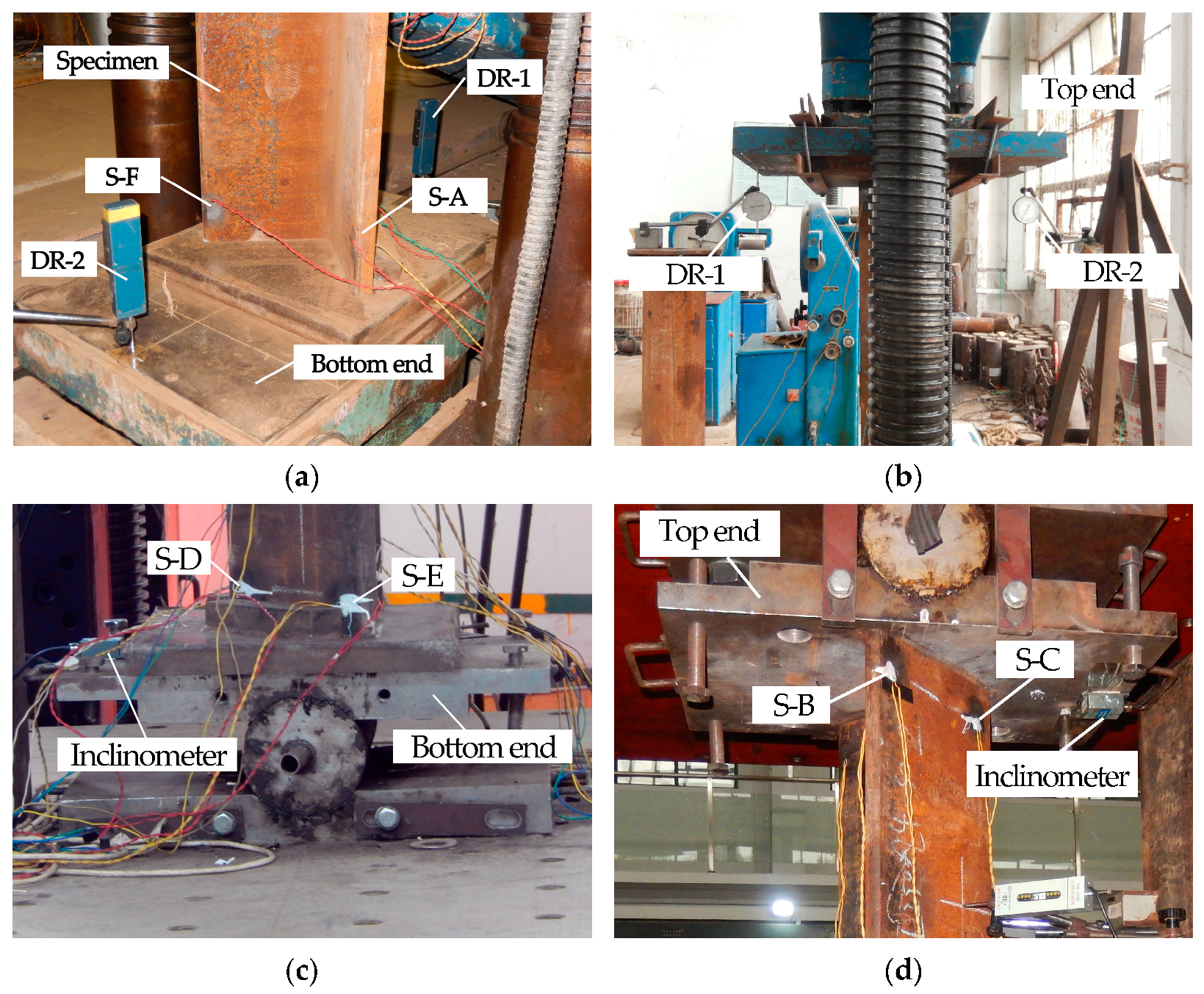
2.4. Test Configuration

In order to accurately obtain the distribution and change of the cross-sectional stress of the specimens under axial compression, six strain measuring points (S-1~S-6) were set at the middle section of the specimens. The horizontal displacement of the specimens under axial compression was measured by two displacement gauges. The displacement measuring points (D-1~D-2) were set at the centroid of the middle section of the specimens. As for the vertical displacement, it was measured by two displacement gauges, and two displacement measuring points (D-3~D-4) were set at the bottom plate and top plate of the specimens. The arrangement of measuring points is shown in Figure 6.
The loading process includes the following three stages: centering, staged loading, and ultimate state and unloading.
(1)
Centering: It includes rough centering and fine centering. Rough centering is to pre-mark the position of the centroid of the specimen on the bottom plate of the end and then coincide the centroid of the specimen with it. A fine centering is achieved by applying a load of no more than 100 kN to the specimen. Then, adjust the position of the specimen according to the measured strain data until the values of the six strain measurement points stay the same.
(2)
Step load testing: It includes three stages, as shown in Table 4.
(3)
Ultimate state and unloading: When the following situations occur during the test, it indicates that the specimen has reached the ultimate state: (1) The load no longer increases, but the displacement data is still changing continuously and the growth rate is relatively fast; (2) The strain data suddenly increases and may even exceed the range of measurement, resulting in overflow failure; and (3) The load can no longer increase and fall back. When the specimen reaches the ultimate state, the loading should be stopped immediately and unloaded slowly.

3. Test Results and Analysis
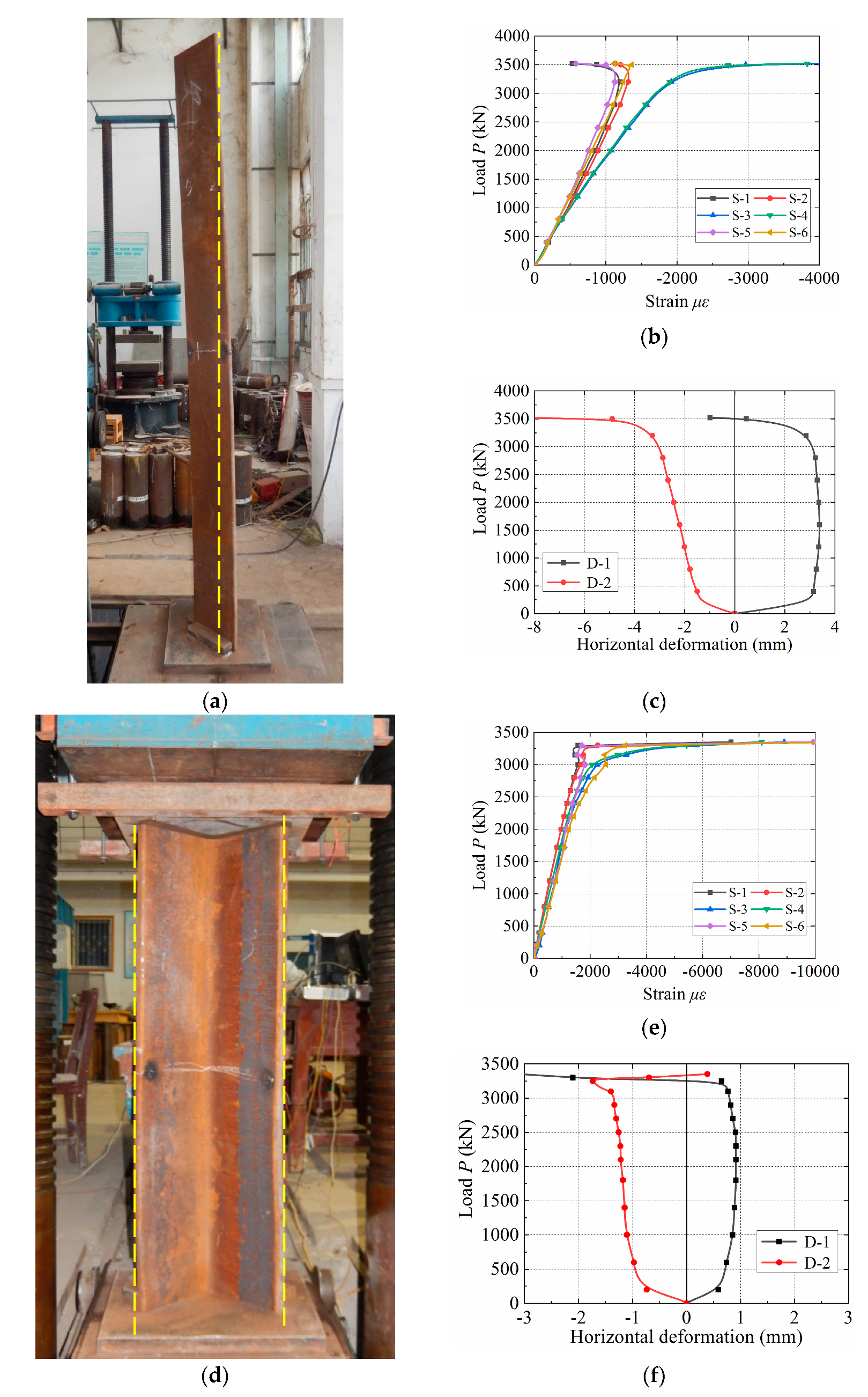
The results of the axial compression test include the tested buckling modes and tested buckling capacity Pu. In order to quantify the axial compression stability of Q345 LAS columns more directly, the tested buckling factor φt was calculated by Equation (9). The following FE results also used the same method.
φ t = P u A f y
where A is the cross-sectional area and fy is the yield strength.
In order to eliminate the influence of the steel strength and elastic modulus on the stability, the non-dimensioned slenderness λn was calculated by Equation (10).
λ n = λ 0 π f y E

3.1. Buckling Modes

Through axial compression tests on 96 Q345 LAS columns, it was found that there were two overall buckling modes, flexural buckling and flexural–torsional buckling, which are shown in Table 5. Two specimens with typical overall buckling modes were presented in Figure 7. The positive and negative values of the horizontal deformation in Figure 7c,f indicated the moving direction of the measuring points. The positive value denotes the measuring points moving towards the heel of the angle. The negative value denotes the measuring points moving towards the toe of the angle.
It can be seen from Figure 7 that at the initial stage of loading, the values of the six strain measuring points were relatively consistent and showed an approximately linear increase with the increase in load, indicating that the centering process was good. The two measuring points (S-3 and S-4) on the heel of the angle were always under compression, and the growth rate accelerated when approaching the buckling capacity. However, with the further increase in the load, the strain values of the four measuring points (S-1 and S-2, S-5 and S-6) at the toe of the angle were different due to the different buckling modes. For the specimens with flexural buckling, the stress state of the toe of the angle changed from compression to tension. Meanwhile, the displacements in the middle of the specimens were also developing in the same direction at this moment, which was in harmony with the deformation of the specimens, which is convex outward. However, for the specimens with flexural–torsional buckling, a short unloading period appeared in the stress state at the toe of the angle. Then, with the increase in the load, the stress values continued to increase. At this moment, one of the displacement values also increased in the opposite direction, indicating torsional deformation in the middle of the specimen when buckling. Nevertheless, the amount of deformation was relatively small, so the torsional deformation was not noticeable. In addition, no local buckling was found in the tests. The reason is that the width–thickness ratio of Q345 LAS columns is small, usually between 8 and 12.
It can be seen from Table 5 that only six specimens failed in flexural–torsional buckling, accounting for 6.25% of the total number of specimens, and the buckling modes of the rest of the specimens were flexural–torsional buckling, accounting for 93.75% of the total number of specimens. The slenderness of the specimens that failed in flexural–torsional buckling was all 30, but not all three specimens in the same section failed in the same buckling mode. There were 24 members with a nominal slenderness of 30, except for six specimens that failed in flexural–torsional buckling. The rest of the 18 specimens still failed in flexural buckling. It showed that the buckling mode of Q345 LAS columns under axial compression is still flexural buckling around the y-y axis, which was consistent with the analysis results of Chen [17]. However, the possible reason is the torsional deformation in the initial imperfections. The lengths of these specimens were too short to measure the initial imperfections accurately enough.

3.2. Buckling Capacity

The buckling capacity of 96 Q345 LAS columns under axial compression was summarized in Table 5. The tested buckling factor φt and the non-dimension slenderness λn were calculated by Equations (9) and (10), respectively, and the results are listed in Table 5.
As is shown in Figure 8, compared with the column curves of the design specifications, most of the tested buckling factors were higher than the corresponding column curves in each specification, indicating that the current specification is conservative in calculating the axial compression stability of the Q345 LAS columns. For GB50017-2017, all of the tested buckling factors were higher than curve b, which was 9.8% higher on average, and the standard deviation was 0.048. Even though compared with curve a, the tested buckling factors were 3.3% higher on average, and the standard deviation was 0.049. It proved that using curve a instead of curve b when calculating the buckling capacity of Q345 LAS columns in GB50017-2017 is reasonable. For Eurocode 3, all of the tested buckling factors were higher than curve b, which was 8.2% higher on average, and the standard deviation was 0.049. Compared with curves a0 and a, the tested buckling factors were 0.4% and 3.4% higher on average, and the standard deviation was 0.049 and 0.046, respectively. It showed that curve b in Eurocode 3 underestimates the buckling capacity of Q345 LAS columns. As for curve a0, it is specially formulated for high-strength steel. Hence, curve a is more suitable in Eurocode 3. For ASCE 10-15 and ANSI/AISC 360-16, these specifications only use one column curve to cover all the strengths and cross-sections. ASCE 10-15 is closer to the tested results of the short column, which were 1.9% higher on average, and the standard deviation was 0.048. ANSI/AISC 360-16 is slightly conservative; its values were 6.2% higher on average, and the standard deviation was 0.047.
The reasons for the high buckling factors of the specimens were:
(1)
The initial imperfections of the specimens were quite small, lower than the 1/1000L adopted in the specification.
(2)
In some specifications, it is considered that the buckling mode of the short column is flexural–torsional buckling, which is inconsistent with the test results, resulting in a low buckling factor in the specification.
(3)
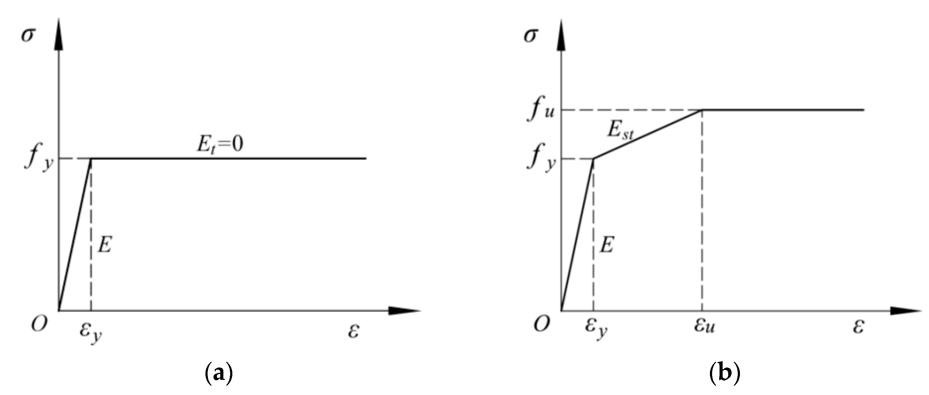
Compared with Q235 steel, Q345 steel has a shorter yield plateau. However, in the current specifications, the constitutive model of Q345 steel adopts the perfect elastic–plastic model, which underestimates the buckling capacity of the specimens.
(4)
It can be seen from Figure 7 that the horizontal deformation of the short specimens was not noticeable before buckling, and the yield plateau of Q345 steel is shorter than that of Q235 steel. It made Q345 LAS columns soon come into strain-hardening progress without significant plastic deformations as Q235 steel columns. This is an inelastic stage buckling, and the sectional stress σ may be greater than the yield strength fy, resulting in the buckling factor exceeding 1.0.

4. Finite Element Model and Validation

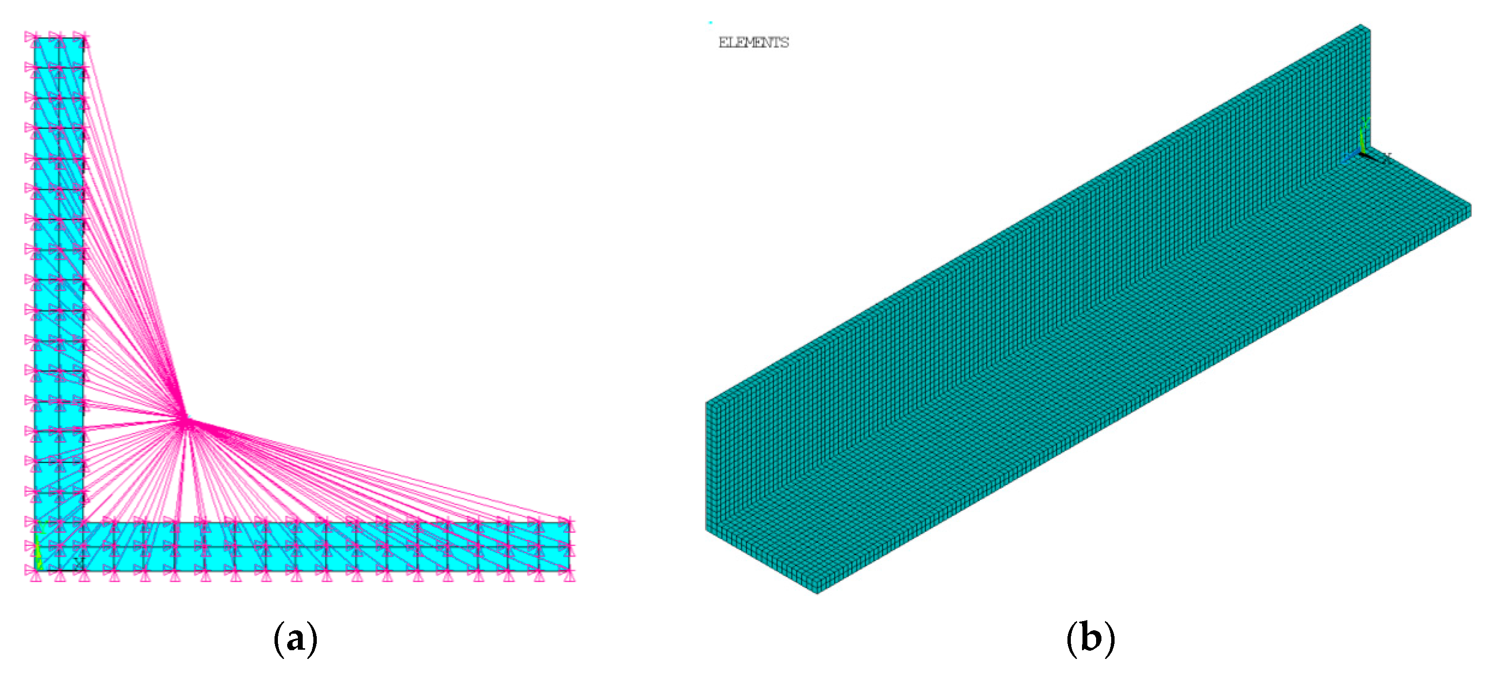
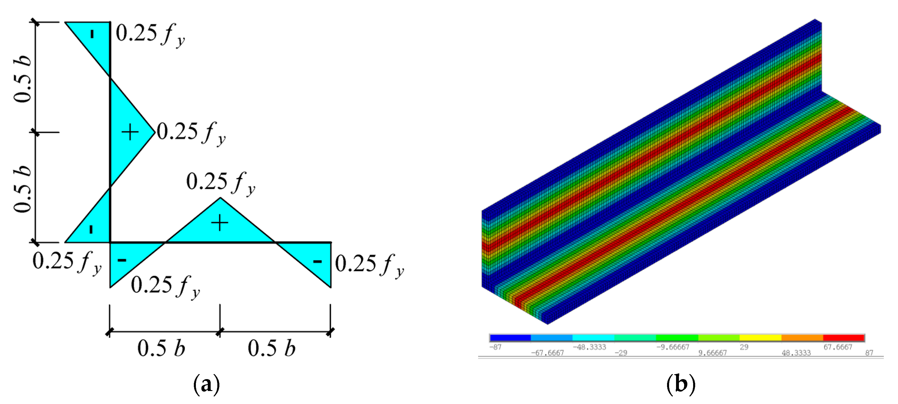
4.1. Finite Element Model

The finite element model of Q345 LAS columns was developed using ANSYS. The large-section angle steel is thicker than normal, and the width–thickness ratio of some specimens is less than 10. Further, the model must be able to simulate flexural buckling and flexural–torsional buckling. Hence, the Solid 185 element is more suitable [2] than the shell element or beam element.
The constraints of the FE model were hinged at both ends. Firstly, create one Mass21 element at the centroid of the section. Secondly, use the constraint equation command (Cerig) to tie the Mass21 element and all the section nodes together, forming a rigid domain, as shown in Figure 9a. Thirdly, release the rotational degree of freedom of the Mass21 element and constrain its translational degree of freedom.
In order to make the elements mesh regularly and uniformly, the FE model was meshed through sweeping. The mesh size along the thickness direction was set to no greater than 10 mm, and the mesh model is shown in Figure 9b.
For the constitutive model in the current design specifications, the perfect elastic–plastic model is used for Q345 and the three-stage model is used for high-strength steel [26,27], as is shown in Figure 10. The test results showed that the buckling capacity of Q345 LAS columns is underestimated by using the perfect elastic–plastic model. However, Q345 steel is not a high-strength steel, so the three-stage model cannot be used for Q345 LAS columns.
Based on the material properties of Q345, a five-stage constitutive model proposed by Yun et al. [28,29] was used for the FE model, which can accurately describe the stress–strain relationship of hot-rolled steel with an obvious yield plateau. The five-stage model introduces two material parameters: C1 and C2. C1 represents the cut-off strain coefficient, which is to avoid over-predictions of material strength. C2 is used to define the strain-hardening slope. The five-stage model is shown in Figure 11a. The comparison between the tested stress–strain curve and the five-stage model is shown in Figure 11b, and it indicates the five-stage model can describe the stress–strain relationship of Q345 accurately. Poisson’s ratio was defined as 0.3. All the material properties were determined according to the tension coupon results in Table 1.
The residual stress distribution model of the FE model adopted the results of Ban et al. [14,15], and the model is shown in Figure 12a. The finite-element model’s application of residual stress is shown in Figure 12b.
In order to apply the initial imperfections to the FE model, the eigenvalue buckling analysis of the specimen was performed to get the first-order overall buckling mode. Based on the measured initial imperfections in Table 2, use the Upgeom command to update the first-order mode. Finally, the new first-order overall buckling mode was used as the initial deformation of the specimen. The arc-length method was used for nonlinear buckling analysis.

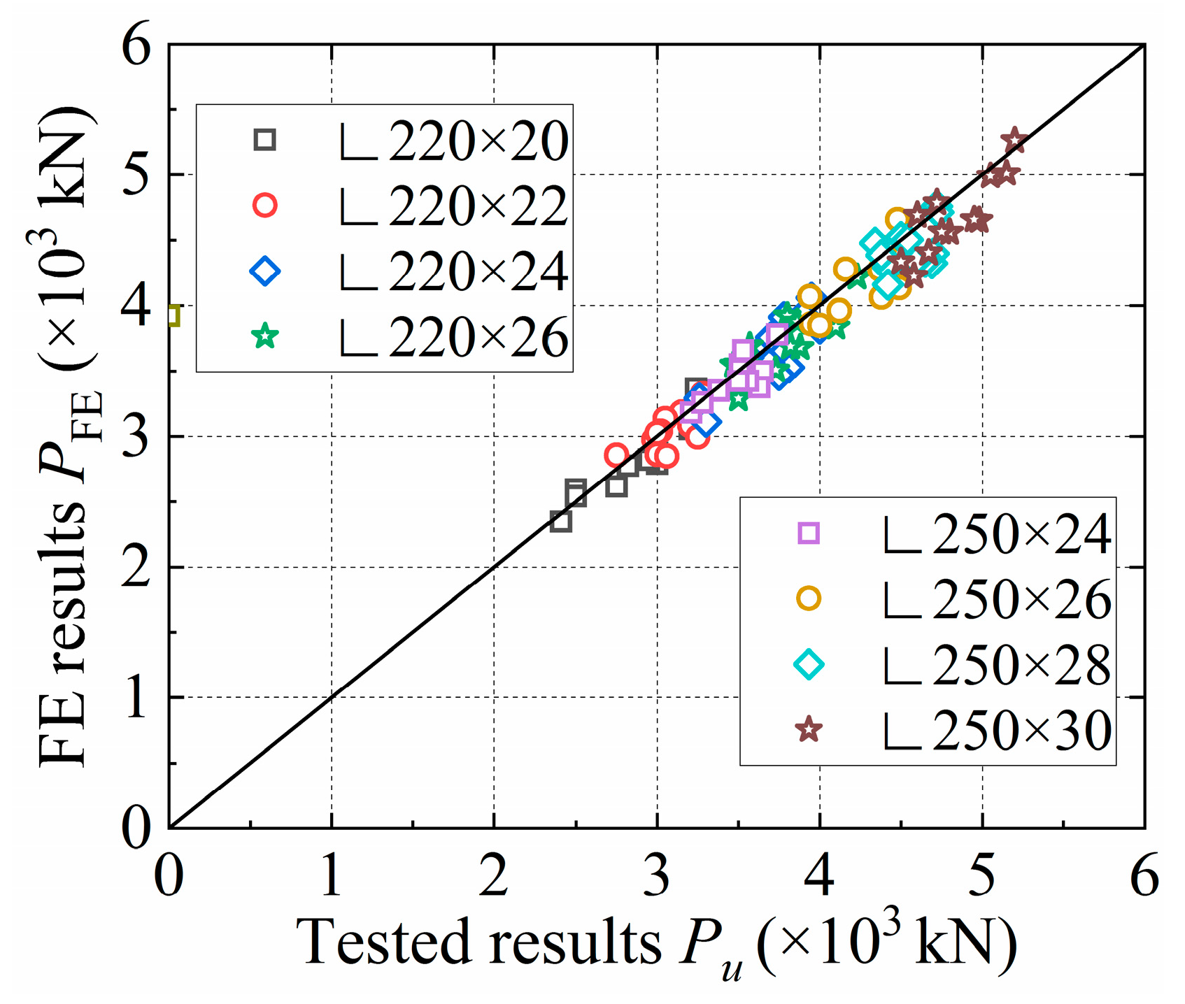
4.2. Model Validation

The comparison result between the FE model (PFE is the buckling capacity of the FE model) and the test is shown in Figure 13. The buckling factor φF calculated by the FE model is listed in Table 5. These two values were very close; the finite element results were 2% lower on average, and the standard deviation was 0.035. It showed that this FE model is accurate and reliable enough for Q345 LAS columns and can be used for subsequent analysis and discussion.

5. Discussion and Design Approach

5.1. Discussion

Previous research shows that the high material strength (fy ≥ 460 MPa) is the main reason for the high buckling capacity of high-strength LAS columns. The LAS columns fabricated from Q235 steel were uneconomic. Therefore, the commonly used LAS materials mainly include Q345, Q420, and Q460, and they all have the same material feature: a visible yield plateau in the stress–strain curve.
In order to investigate how the mechanical properties affect the buckling capacity of Q345 LAS columns under axial compression, a total of 36 FE models for LAS columns were established with different material strengths (Q345, Q420, and Q460). The cross-section is ∟220 × 26, and the slenderness λ is 20~160. The nonlinear buckling analysis was performed on these FE models. Then, the FE buckling factors were drawn as a column curve and compared with the specifications of various countries, as shown in Figure 14.
It can be seen from Figure 14 that even for normal-strength LAS columns, the buckling factor still increased with the increase in strength, but the increase was not as significant as that of high-strength steel. The buckling factor of Q420 LAS columns was approximately 1.8~2.6% higher than that of Q345 on average. The buckling factor of Q460 LAS columns was approximately 2.8~4% higher than that of Q345 on average. In addition, this increase was mainly concentrated in short and medium columns. The reason is that short columns have entered the inelastic stage when it is buckling. On the contrary, the buckling factor of the long columns was not affected by the strength of the steel. Because long columns still stay in the elastic stage when it is buckling, the buckling capacity of the columns was determined by the Euler formula, which means determined by the slenderness.
The main reasons for the high buckling factor of short columns include the following:
(1)
Previous research has always selected flexural–torsional buckling as the buckling mode of short LAS columns to simulate and analyze. However, it can be seen from the test results that normal-strength LAS columns failed in the flexural buckling. The width–thickness ratio of LAS columns is small, so their local stability is good and local buckling does not occur. Therefore, this paper used flexural buckling as the buckling mode of short LAS columns, which increased the buckling factor, which is consistent with the test results.
(2)
The perfect elastic–plastic model is used for the stress–strain relationship of normal-strength LAS columns in specifications, ignoring the influence of strain-stiffening. However, when the stress of the short column is close to the yield strength, its displacement still develops little so that it will not immediately buckle when the stress on the section of the column exceeds the yield strength, resulting in a higher buckling capacity. In this paper, the five-stage constitutive model was used in the FE model, which fully considers the influence of strain stiffening, so the calculation results were higher than the specifications.
(3)
With the increase in steel strength, the yield plateau of ordinary low-alloy structural steel is also gradually shortened. Although its reduction is not as large as that of high-strength steel, it is still a positive factor for columns to enter the strain-hardening process as soon as possible. The influence of strain hardening on the buckling capacity cannot be ignored.
In order to study the influence of section size on the buckling factor of Q345 LAS columns, a total of 72 Q345 LAS columns FE models were established with different section sizes (∟250 × 20 (b/t = 12.5), ∟220 × 20 (b/t = 11.0), ∟250 × 24 (b/t = 10.4), ∟220 × 24 (b/t = 9.2), ∟220 × 26 (b/t = 8.5), and ∟250 × 35 (b/t = 7.14)), and the slenderness λ is 20~160. The FE buckling factors were drawn as a column curve and compared with the specifications of various countries, as shown in Figure 15 and Table 6. These results were also employed in the following study of the design approach.
Referring to Figure 15, the change in cross-section size has little effect on the buckling capacity of Q345 LAS columns. It can be ignored, similar to the analysis results of Chen [17] on Q345 normal-section angled steel columns.
The FE result points plotted in Figure 15 formed a new column curve. In this curve, for short columns with λn < 0.419, the FE buckling factors of Q345 LAS columns were all larger than 1, exceeding the conditional control line (σ = fy) in the Euler curve. It indicated that the bearing capacity of Q345 LAS columns in this range had been determined by strength rather than stability. When λn > 2.0, the axial-compression stability coefficient was very close to the Euler curve, and the column was similar to a perfectly elastic column.
As is shown in Table 6, the FE buckling factor of the Q345 LAS columns was very close to the curve a in GB50017-2017, but there was still a visible difference in the short column, in which all of the buckling factors in GB50017-2017 are always less than 1.0. The FE buckling factors were 1.77% higher than those of curve a on average, and the standard deviation was 0.0298. Compared with the curve b in Eurocode 3, the FE buckling factors were 11.66% higher than that of the curve b on average, and the standard deviation was 0.0280. However, the column curve in Eurocode 3 sets a straight line for the short column, which fully uses the bearing capacity of LAS columns within this range. For ASCE 10-15 and AISC 360-16, since only one column curve is set to cover all the strength and section types, the relative errors of the result were naturally larger, with the FE buckling factors being −4.58% and 4.78% higher than that of the curves on average, respectively. Meanwhile, for the ASCE 10-15, the standard deviation was 0.0732, which was the largest of these seven curves. Therefore, these two curves are unsuitable for calculating the buckling capacity of Q345 LAS columns.
In summary, the curve a in Eurocode 3 and GB 50017-2003 can be used to predict buckling the capacity of Q345 LAS columns conservatively, but these curves can still be further optimized in the short column range.

5.2. Design Approach

In order to obtain a more accurate buckling capacity for Q345 LAS columns, it is necessary to optimize the column curve in the current specification. The column curves used in Eurocode 3 and GB50017-2017 refer to the Perry formula, and the column curves in GB50017-2017 can be expressed by Equations (11) and (12). When λn ≤ 0.215:
φ = 1 α 1 λ n 2
When λn > 0.215:
φ = 1 2 λ n 2 [ ( α 2 + α 3 λ n + λ n 2 ) ( α 2 + α 3 λ n + λ n 2 ) 2 4 λ n 2 ]
where α1, α2, and α3 were the imperfection coefficients. As for the Q345 LAS columns, the α1 = 0.65, α2 = 0.986, and α3 = 0.152.
For the new curve, these imperfection coefficients were fitted using the results of the FE model. The fitting data included six kinds of section specifications, 23 kinds of slenderness, and a total of 78 (λn, φ) data points. Then, use Equation (12) as the basic form of the formula to perform nonlinear fitting, and the fitting results for α2 and α3 were 0.899 and 0.241, respectively. Moreover, when the buckling factor is larger than 1.0, use the method in Eurocode 3, where a straight line (φ = 1.0) is used to replace it. It indicated that the bearing capacity is determined by strength rather than stability for short columns, so α1 is 0. Then, bring φ = 1.0 into Equation (12), and the corresponding λn is obtained as 0.419. Based on the above results, a new column curve suitable for Q345 LAS columns was proposed, and it can be expressed by Equations (13) and (14). When λn ≤ 0.419:
φ = 1.0
When λn > 0.419:
φ = 1 2 λ n 2 [ ( 0.899 + 0.241 λ n + λ n 2 ) ( 0.899 + 0.241 λ n + λ n 2 ) 2 4 λ n 2 ]
The proposed φ-λn curve was obtained by Equations (13) and (14), as illustrated in Figure 16. The comparison of the proposed column curve and FE model results is shown in Figure 16 and Table 6. It indicated that the proposed column curve had significant accuracy. The results of the FE model were on average 1.18% higher than the recommended column curve, and the standard deviation was 0.017. The new column is more suitable for predicting the buckling capacity of Q345 LAS columns.

6. Conclusions

A total of 96 Q345 LAS columns (including eight kinds of cross-sections and four kinds of slenderness) were tested under axial compression, and the influence of the rotational stiffness of the end was considered. The buckling modes and buckling capacity were obtained from tests. The FE model for Q345 LAS columns was established and verified. Based on the FE model, parametric analyses and discussions were conducted. Finally, a new column curve suitable for Q345 LAS columns was proposed. The following conclusions can be drawn from this study:
(1)
The slenderness of the specimens under axial compression can be corrected by measuring the rotational stiffness of the ends, and a more accurate buckling capacity can be obtained. The buckling mode of Q345 LAS columns was flexural buckling. Local buckling does not occur due to the small width–thickness ratio. Initial imperfections in specimens were the main reason for the flexural–torsional buckling of short specimens.
(2)
The tested buckling capacity of Q345 LAS columns was significantly higher than the corresponding calculated value in the current design specifications. The current specifications were conservative in calculating such components, especially for predicting the components with small slenderness.
(3)
A FE model of the Q345 LAS column was established based on the measured geometric properties and initial imperfections. The results of the test verified that the FE model was accurate enough.
(4)
The material strength, constitutive model, and buckling mode were the main factors that affected the buckling capacity of Q345 LAS columns. The change in cross-section size has little effect on the buckling capacity of Q345 LAS columns, which can be ignored.
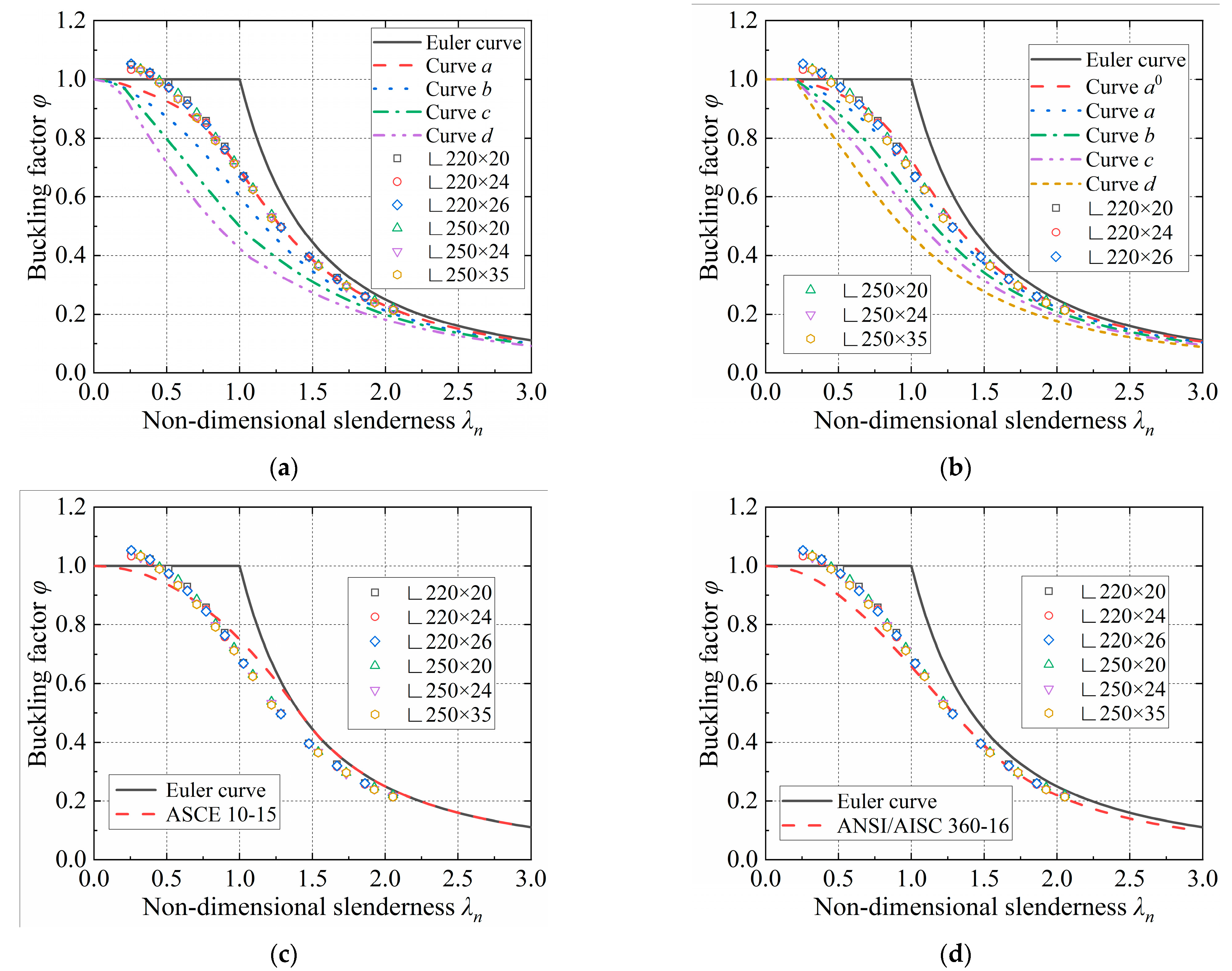
(5)
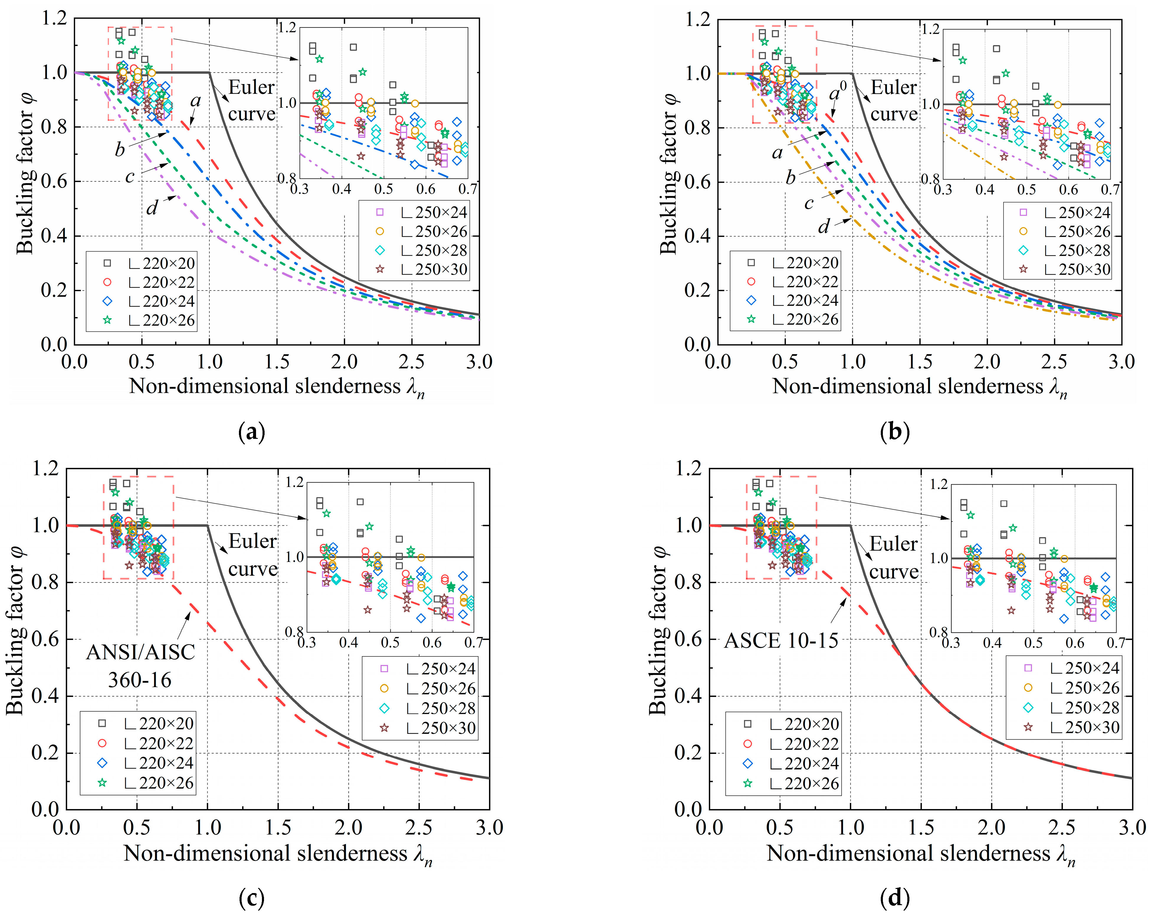
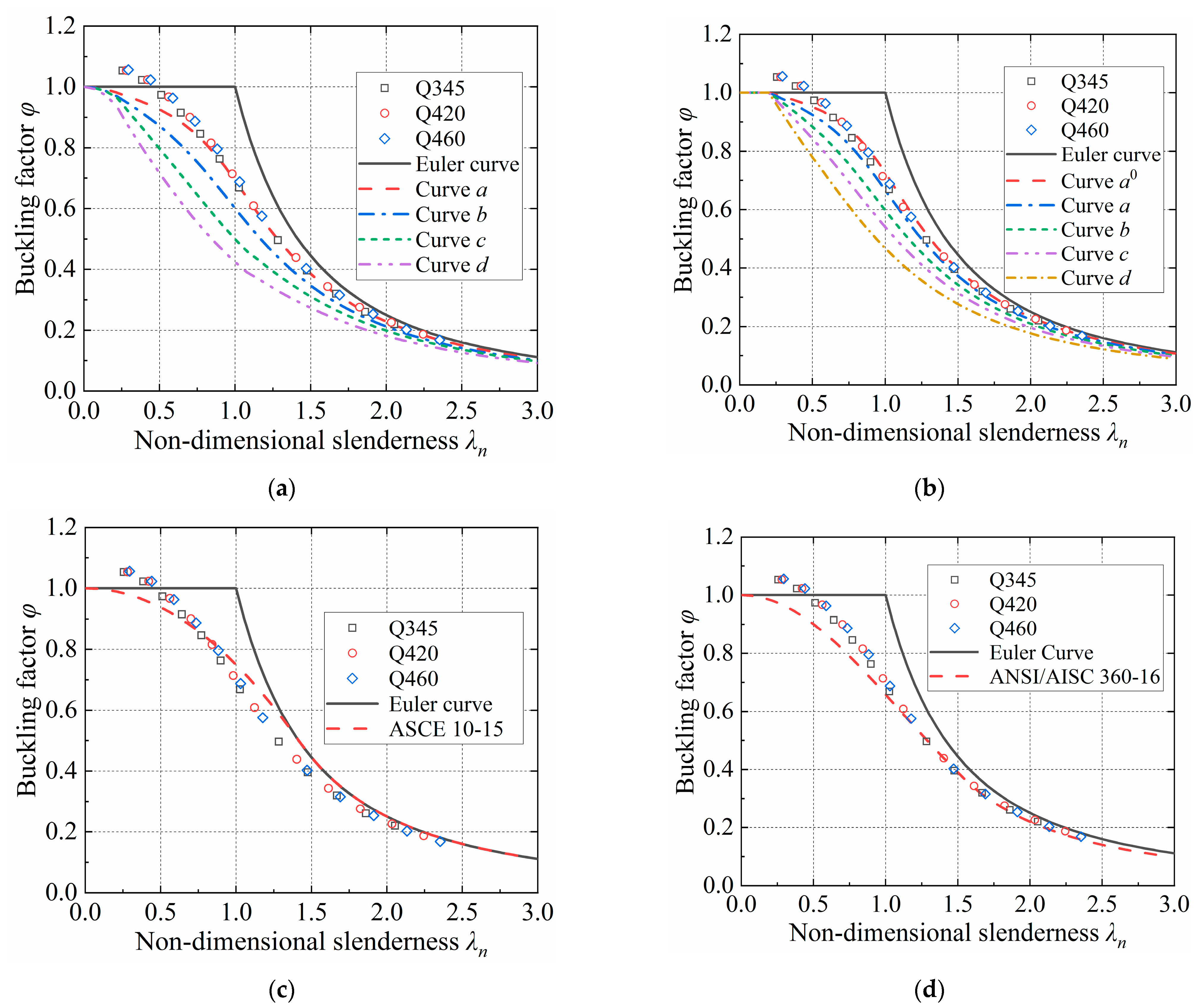
The FE buckling factors of Q345 LAS columns were higher than the predicted values in the current specification. The curve a in GB50017-2017 was the closest, followed by the curve a in Eurocode 3. While the prediction values of ASCE 10-15 and AISC 360-16 were not accurate enough.
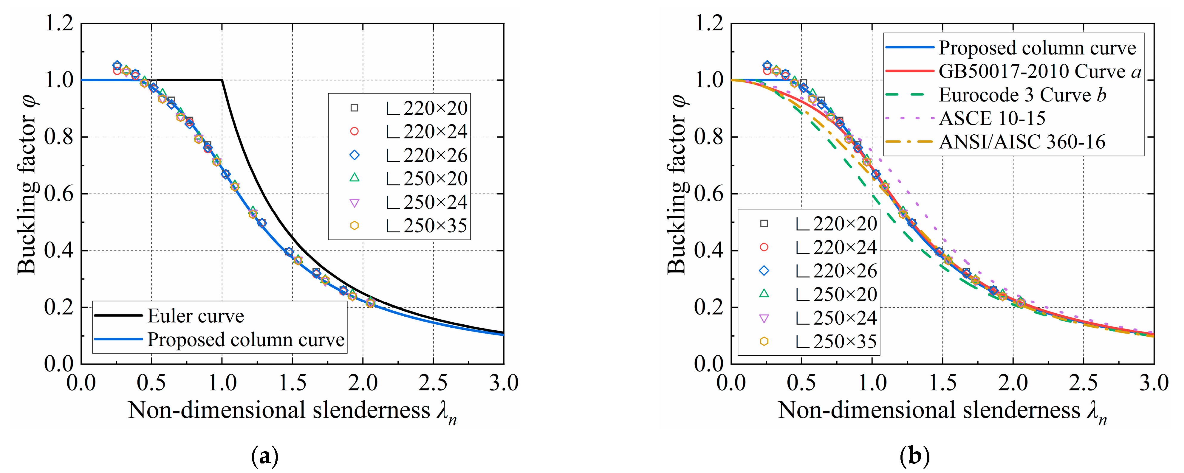
(6)
A new column curve was proposed and proved accurate enough for Q345 LAS columns under axial compression. This new curve thoroughly considered the excellent bearing capacity of short columns. The curve can be expressed as follows: when λn ≤ 0.419, φ = 1.0. When λn > 0.419, the curve can be expressed by Equation (14).

Author Contributions

Conceptualization, H.C. (Haoyuan Chen) and Y.G.; methodology, H.C. (Haoyuan Chen) and K.C.; software, H.C. (Haoyuan Chen) and H.C. (Hao Chen); validation, H.C. (Haoyuan Chen), H.C. (Hao Chen) and K.C.; formal analysis, H.C. (Haoyuan Chen); investigation, H.C. (Hao Chen); resources, Y.G.; data curation, H.C. (Haoyuan Chen); writing—original draft preparation, H.C. (Haoyuan Chen); writing—review and editing, Y.G.; visualization, H.C. (Haoyuan Chen) and K.C.; supervision, Y.G.; project administration, Y.G.; funding acquisition, Y.G. All authors have read and agreed to the published version of the manuscript.

Funding

This research was funded by the National Natural Science Foundation of China (No. 51378401) and Research Plan for PhD Short-time Mobility Program of Wuhan University.

Data Availability Statement

All the data supporting the reported results can be found in the manuscript.

Acknowledgments

The authors wish to acknowledge the financial support from the National Natural Science Foundation of China (No. 51378401) and the Research Plan for the PhD Short-time Mobility Program of Wuhan University.

Conflicts of Interest

The authors declare no conflict of interest.

References

  1. Shi, G.; Liu, Z.; Ban, H.Y.; Shi, Y.J.; Wang, Y.Q. Tests and finite element analysis on the local buckling of 420MPa steel equal angle columns under axial compression. Steel Compos. Struct. 2012, 12, 31–51. [Google Scholar] [CrossRef]
  2. Ban, H.Y.; Shi, G.; Shi, Y.J.; Wang, Y.Q. Overall buckling behavior of 460 MPa high strength steel columns: Experimental investigation and design method. J. Constr. Steel Res. 2012, 74, 140–150. [Google Scholar] [CrossRef]
  3. Sun, Y.; Guo, Y.J.; Chen, H.Y.; Cao, K. Stability of large-size and high-strength steel angle sections affected by support constraint. Int. J. Steel Struct. 2021, 21, 85–99. [Google Scholar] [CrossRef]
  4. Ye, J.; Rasmussen, K.J. Compression strength of unstiffened elements in cold-reduced high strength steel. J. Struct. Eng. 2008, 134, 189–197. [Google Scholar] [CrossRef]
  5. Cao, K.; Guo, Y.J.; Zeng, D.W. Buckling behavior of large-section and 420 MPa high-strength angle steel columns. J. Constr. Steel Res. 2015, 111, 11–20. [Google Scholar] [CrossRef]
  6. Shi, G.; Chen, X.S. Research advances in HSS structures at Tsinghua University and codification of the design specification. Steel Constr.-Des. Res. 2018, 11, 286–293. [Google Scholar] [CrossRef]
  7. Bijlaard, F.; Veljkovic, M.; Shi, G.; Qiang, X.H. Implementation of high-strength, high-performance steel structures. Steel Constr.-Des. Res. 2018, 11, 247–248. [Google Scholar] [CrossRef]
  8. BS EN 1993-1-1; Eurocode3: Design of Steel Structures: Part 1-1: General Rules and Rules for Buildings. BSI: London, UK, 2005.
  9. GB50017-2003; Code for Design of Steel Structures. China Architecture & Building Press: Beijing, China, 2003. (In Chinese)
  10. ASCE 10-2015; Design of Latticed Steel Transmission Structures. ASCE: Washington, DC, USA, 2015.
  11. ANSI/AISC 360-2016; Specification for Structural Steel Buildings. AISC: Chicago, IL, USA, 2016.
  12. GB50017-2017; Standard for Design of Steel Structures. China Architecture & Building Press: Beijing, China, 2017. (In Chinese)
  13. Moze, P.; Cajot, L.G.; Sinur, F. Residual stress distribution of large steel equal leg angles. Eng. Struct. 2014, 71, 35–47. [Google Scholar] [CrossRef]
  14. Ban, H.Y.; Shi, G.; Shi, Y.J.; Wang, Y.Q. Column buckling tests of 420 MPa high strength steel single equal angles. Int. J. Struct. Stab. Dyn. 2013, 13, 1250069-1–1250069-23. [Google Scholar] [CrossRef]
  15. Ban, H.Y.; Shi, G.; Shi, Y.J. Residual stress tests of high-strength steel equal angles. J. Struct. Eng. 2012, 138, 1446–1454. [Google Scholar] [CrossRef]
  16. Shi, G.; Zhang, Z.Q.; Zhou, L.; Gao, Y. Experimental study and modeling of residual stresses of Q420 large-section angles. J. Constr. Steel Res. 2020, 167, 105958. [Google Scholar] [CrossRef]
  17. Chen, S.F. Elastic and inelastic stability capacity of single angle under axial compression. J. Build. Struct. 2012, 33, 134–141. (In Chinese) [Google Scholar]
  18. Shi, G.; Zhou, W.J.; Bai, Y.; Lin, C.C. Local buckling of steel equal angle members with normal and high strengths. Int. J. Steel Struct. 2014, 14, 447–455. [Google Scholar] [CrossRef]
  19. Qu, S.Z.; Wang, J.Y.; Guo, Y.H.; Hao, J.P.; Yang, X.C. Experiment and code-based study on high-strength steel pin-ended angles under axial compression. Thin-Walled Struct. 2020, 149, 106541-1–106541-22. [Google Scholar] [CrossRef]
  20. Cao, K.; Guo, Y.J.; Xu, J. Buckling analysis of columns ended by rotation-stiffness spring hinges. Int. J. Steel Struct. 2016, 16, 1–9. [Google Scholar] [CrossRef]
  21. Liu, H.Y.; Li, Z.L.; Huang, Z.L. A study on the bearing capacity of angle steel members in transmission towers. Prog. Steel Build. Struct. 2021, 23, 47–55. (In Chinese) [Google Scholar]
  22. BS EN 10002-1; Metallic Materials Tensile Testing, Part 1: Method of Test at Ambient Temperature. BSI: London, UK, 2001.
  23. Huang, X.; Yuan, Y.; Zhao, J.; Wei, C.C. Comparative study on ultra-low-cycle-fatigue behavior of Q235 normal-steel and Q690 high-strength steel. J. Constr. Steel Res. 2022, 194, 107308. [Google Scholar] [CrossRef]
  24. Ban, H.Y.; Shi, G.; Shi, Y.J.; Mark, A.B. Experimental investigation of the overall buckling behaviour of 960 MPa high strength steel columns. J. Constr. Steel Res. 2013, 88, 256–266. [Google Scholar] [CrossRef]
  25. Zhang, L.L.; Wang, F.Y.; Liang, Y.T.; Zhao, O. Press-braked S690 high strength steel equal-leg angle and plain channel section stub columns: Testing, numerical simulation and design. Eng. Struct. 2019, 201, 109764. [Google Scholar] [CrossRef]
  26. Wang, Y.Z.; Kanvinde, A.; Li, G.Q.; Wang, Y.B. A new constitutive model for high strength structural steels. J. Constr. Steel Res. 2021, 182, 106646. [Google Scholar] [CrossRef]
  27. Kim, J.H.; Kim, D.; Han, H.N.; Barlat, F.; Lee, M.G. Strain rate dependent tensile behavior of advanced high strength steels: Experiment and constitutive modeling. Mater. Sci. Eng. A 2013, 559, 222–231. [Google Scholar] [CrossRef]
  28. Yun, X.; Gardner, L.; Boissonnade, N. The continuous strength method for the design of hot-rolled steel cross-sections. Eng. Struct. 2018, 157, 179–191. [Google Scholar] [CrossRef]
  29. Yang, X.; Yang, H.; Gardner, L.; Wang, Y. A continuous dynamic constitutive model for normal- and high-strength structural steels. J. Constr. Steel Res. 2022, 192, 107254. [Google Scholar] [CrossRef]
Figure 1. Mechanical testing: (a) The size of tension coupon; (b) Stress–strain curves.
Buildings 13 01030 g001
Figure 2. Sectional geometric properties and initial imperfections.
Buildings 13 01030 g002
Figure 3. The measurement arrangement of rotation stiffness.
Buildings 13 01030 g003
Figure 4. The actual set-up: (a) The bottom of 500 t; (b) The top of 500 t; (c) The bottom of 3000 t; (d) The top of 3000 t.
Buildings 13 01030 g004
Figure 5. The load-rotation stiffness (P-R) curves: (a) The bottom of 500 t; (b) The top of 500 t; (c) The bottom of 3000 t; (d) The top of 3000 t.
Buildings 13 01030 g005
Figure 6. Test configuration: (a) 500 t illustration; (b) 3000 t illustration; (c) measurement illustration.
Buildings 13 01030 g006
Figure 7. Test results: (a) ∟220 × 26-60-1, flexural buckling; (b) ∟220 × 26-60-1, load–strain curve; (c) ∟220 × 26-60-1, load–horizontal deformation curve; (d) ∟220 × 22-30-1, flexural–torsional buckling; (e) ∟220 × 22-30-1, load–strain curve; (f) ∟220 × 22-30-1, load–horizontal deformation curve.
Buildings 13 01030 g007
Figure 8. Comparison between test results and design curves: (a) GB50017-2017; (b) Eurocode 3; (c) ASCE 10-15; (d) ANSI/AISC 360-10.
Buildings 13 01030 g008
Figure 9. FE model: (a) rigid domain; (b) the meshed FE model.
Buildings 13 01030 g009
Figure 10. Constitutive model in specifications: (a) the perfect elastic–plastic model; (b) the three-stage model. Et is the tangent modulus, Est is the slope.
Buildings 13 01030 g010
Figure 11. Constitutive model in the FE model: (a) the five-stage model; (b) the comparison between tested stress–strain curve and five-stage model.
Buildings 13 01030 g011
Figure 12. The residual stress: (a) the residual stress distribution model; (b) the finite-element model applied residual stress.
Buildings 13 01030 g012
Figure 13. Comparison between FE results and tested results.
Buildings 13 01030 g013
Figure 14. Comparison between FE results (different strengths) and design curves: (a) GB50017-2017; (b) Eurocode 3; (c) ASCE 10-15; (d) ANSI/AISC 360-10.
Buildings 13 01030 g014
Figure 15. Comparison between Q345 LAS FE results (different section sizes) and design curves: (a) GB50017-2017; (b) Eurocode 3; (c) ASCE 10-15; (d) ANSI/AISC 360-10.
Buildings 13 01030 g015
Figure 16. Comparison of the proposed column curve with FE results and design curves: (a) FE results; (b) Design curves.
Buildings 13 01030 g016
Table 1. Tension coupon test results.
Tension Coupon LabelElastic Modulus
E (MPa)
Yield Strength
fy (MPa)
Ultimate Tensile Stress
fu (MPa)
fu/fy
∟220 × 202.05 × 1053355091.52
∟220 × 222.06 × 1053485191.49
∟220 × 242.08 × 1053905501.41
∟220 × 262.03 × 1053525181.47
∟250 × 242.06 × 1053355051.51
∟250 × 262.13 × 1053645651.55
∟250 × 282.10 × 1053785541.47
∟250 × 302.11 × 1053785431.44
Table 2. The measured geometric properties and initial imperfections.
Specimen LabelMeasured Geometric Properties (mm)Initial Imperfections
b0t0l0η (‰)θ (rad)
∟220 × 20-30 1221.520.741031.60.760.003
∟220 × 20-40220.720.351466.00.510.002
∟220 × 20-50221.620.481898.40.420.003
∟220 × 20-60221.720.372333.80.390.003
∟220 × 22-30220.622.561024.90.740.001
∟220 × 22-40222.722.541456.90.770.004
∟220 × 22-50221.222.691889.10.620.002
∟220 × 22-60222.022.672321.50.340.001
∟220 × 24-30221.124.401022.20.690.000
∟220 × 24-40221.224.551453.10.510.006
∟220 × 24-50221.724.671884.60.570.002
∟220 × 24-60221.224.432314.70.310.008
∟220 × 26-30221.826.321019.50.520.007
∟220 × 26-40221.526.581449.40.730.000
∟220 × 26-50221.626.911879.50.580.001
∟220 × 26-60221.226.462309.00.440.000
∟250 × 24-30251.324.701204.70.680.004
∟250 × 24-40252.324.611697.20.440.000
∟250 × 24-50251.424.802188.40.620.005
∟250 × 24-60250.824.762680.10.280.000
∟250 × 26-30251.226.791199.70.370.004
∟250 × 26-40252.726.581688.40.230.004
∟250 × 26-50252.026.192179.80.460.003
∟250 × 26-60251.926.502669.20.330.002
∟250 × 28-30251.528.551195.90.590.003
∟250 × 28-40251.928.421684.50.800.004
∟250 × 28-50252.228.382173.60.450.002
∟250 × 28-60252.028.562663.40.350.003
∟250 × 30-30251.430.441210.00.530.002
∟250 × 30-40251.930.591698.00.520.003
∟250 × 30-50251.830.692185.90.46−0.001
∟250 × 30-60251.330.782673.40.25−0.002
ηmax and θmax 0.800.008
1 ∟220 × 20-30 denotes the three specimens with the same nominal geometric properties of nominal limb width b = 220 mm, nominal thickness t = 20 mm, and nominal slenderness λ = 30.
Table 3. The corrected slenderness ratio.
Tension Coupon Labelλ0
λ = 30λ = 40λ = 50λ = 60
∟220 × 2025.7633.3140.6047.68
∟220 × 2225.9833.6441.0248.19
∟220 × 2426.1833.9241.3948.64
∟220 × 2626.3634.1741.7149.04
∟250 × 2426.8234.8542.6050.14
∟250 × 2626.9735.0842.9150.52
∟250 × 2827.1235.2943.2050.88
∟250 × 3025.4432.6739.5446.13
Table 4. Step load testing.
Load (kN)Loading Speed (kN/s)Increment (kN)
0~15004200
1500~0.8 Pu 12100
>0.8 Pu150
1Pu is the buckling capacity of the specimen.
Table 5. Tested results and comparison with FE results.
Specimen
Label
λnBuckling
Mode
Pu
(kN)
φtφFφF/φtSpecimen
Label
λnBuckling
Mode
Pu
(kN)
φtφFφF/φt
∟220 × 20-30-10.331F 132401.1511.1951.038∟250 × 24-30-10.344F35600.9300.9130.982
∟220 × 20-30-2FT32001.1371.0850.954∟250 × 24-30-2F37400.9770.9871.010
∟220 × 20-30-3FT30001.0660.9910.930∟250 × 24-30-3FT36500.9540.9130.957
∟220 × 20-40-10.428F30001.0661.0200.957∟250 × 24-40-10.447F36300.9490.8810.929
∟220 × 20-40-2F32301.1481.1070.964∟250 × 24-40-2F35100.9170.9271.011
∟220 × 20-40-3F29901.0631.0190.959∟250 × 24-40-3F35300.9220.9551.035
∟220 × 20-50-10.521F27500.9770.9290.951∟250 × 24-50-10.547F35100.9170.9171.000
∟220 × 20-50-2F29501.0481.0020.955∟250 × 24-50-2F35600.9300.8940.961
∟220 × 20-50-3F28201.0020.9860.984∟250 × 24-50-3F35000.9150.8940.977
∟220 × 20-60-10.612F24100.8560.8330.973∟250 × 24-60-10.644F33800.8830.8740.990
∟220 × 20-60-2F25000.8880.9211.037∟250 × 24-60-2F32100.8390.8310.991
∟220 × 20-60-3F25000.8880.9021.015∟250 × 24-60-3F32800.8570.8510.993
∟220 × 22-30-10.340FT32801.0251.0381.013∟250 × 26-30-10.361F43800.9760.9060.928
∟220 × 22-30-2FT32601.0191.0150.996∟250 × 26-30-2F44000.9810.9901.009
∟220 × 22-30-3F31500.9840.9941.010∟250 × 26-30-3FT44901.0010.9220.921
∟220 × 22-40-10.440F32001.0000.9630.963∟250 × 26-40-10.469F45001.0030.9590.956
∟220 × 22-40-2F30500.9530.9791.028∟250 × 26-40-2F43700.9740.9530.979
∟220 × 22-40-3F32501.0160.9350.921∟250 × 26-40-3F44100.9830.9610.978
∟220 × 22-50-10.537F29800.9310.9290.998∟250 × 26-50-10.574F44800.9991.0381.039
∟220 × 22-50-2F30000.9370.8940.954∟250 × 26-50-2F41200.9180.8830.961
∟220 × 22-50-3F30600.9560.8900.931∟250 × 26-50-3F41600.9270.9541.028
∟220 × 22-60-10.630F27500.8590.8921.038∟250 × 26-60-10.676F39500.8810.8600.977
∟220 × 22-60-2F30200.9440.9501.007∟250 × 26-60-2F40000.8920.8580.962
∟220 × 22-60-3F30000.9370.9451.008∟250 × 26-60-3F39400.8780.9071.032
∟220 × 24-30-10.363F37800.9711.0041.034∟250 × 28-30-10.370F47000.9410.8800.936
∟220 × 24-30-2F39501.0141.0421.028∟250 × 28-30-2F46900.9390.8660.922
∟220 × 24-30-3F40001.0270.9820.956∟250 × 28-30-3F47200.9450.9521.008
∟220 × 24-40-10.470F38100.9780.9060.926∟250 × 28-40-10.481F46500.9310.8670.932
∟220 × 24-40-2F39001.0021.0091.007∟250 × 28-40-2F45000.9010.9051.005
∟220 × 24-40-3F37500.9630.9400.976∟250 × 28-40-3F45900.9190.8680.945
∟220 × 24-50-10.573F32600.8370.8441.008∟250 × 28-50-10.589F44200.8850.8590.971
∟220 × 24-50-2F37500.9630.8910.925∟250 × 28-50-2F45400.9090.9020.992
∟220 × 24-50-3F36900.9480.9140.965∟250 × 28-50-3F47300.9470.9430.996
∟220 × 24-60-10.674F33000.8480.7990.942∟250 × 28-60-10.694F43400.8690.8961.032
∟220 × 24-60-2F37000.9500.9651.015∟250 × 28-60-2F44200.8850.8330.941
∟220 × 24-60-3F35600.9140.9261.013∟250 × 28-60-3F43800.8770.8781.002
∟220 × 26-30-10.347F38001.0031.0341.031∟250 × 30-30-10.347F52000.9760.9871.012
∟220 × 26-30-2F42301.1161.1130.997∟250 × 30-30-2F49800.9340.8730.934
∟220 × 26-30-3F38801.0240.9710.949∟250 × 30-30-3F51500.9660.9400.973
∟220 × 26-40-10.450F41001.0821.0120.936∟250 × 30-40-10.445F49500.9290.8740.941
∟220 × 26-40-2F37300.9840.9260.940∟250 × 30-40-2F45800.8590.7930.923
∟220 × 26-40-3F35700.9420.9741.034∟250 × 30-40-3F50500.9480.9360.988
∟220 × 26-50-10.549F35600.9400.9340.995∟250 × 30-50-10.539F48000.9010.8560.950
∟220 × 26-50-2F38601.0191.0221.003∟250 × 30-50-2F46000.8630.8801.020
∟220 × 26-50-3F38201.0080.9730.965∟250 × 30-50-3F47200.8860.8981.014
∟220 × 26-60-10.645F34700.9160.9361.022∟250 × 30-60-10.629F47500.8910.8560.961
∟220 × 26-60-2F35000.9240.8680.940∟250 × 30-60-2F45000.8440.8140.964
∟220 × 26-60-3F34900.9210.9381.018∟250 × 30-60-3F46700.8760.8260.943
Mean value of φF/φt 0.980
Standard deviation of φF/φt 0.035
1 F denotes flexural buckling, FT denotes flexural–torsional buckling.
Table 6. Comparison between Q345 LAS FE results and design curves.
(φFEφCo)/φCo 1GB50017-2017Eurocode 3ASCE 10-15AISC 360-16Proposed
Column Curve
aba0ab
Mean1.77%11.53%−1.30%3.90%11.66%−4.94%4.78%1.18%
Standard deviation0.02980.02680.03330.01620.02800.07320.03640.0177
1 φCo is the buckling factor of specifications.
Disclaimer/Publisher’s Note: The statements, opinions and data contained in all publications are solely those of the individual author(s) and contributor(s) and not of MDPI and/or the editor(s). MDPI and/or the editor(s) disclaim responsibility for any injury to people or property resulting from any ideas, methods, instructions or products referred to in the content.

