Abstract
This article summarizes the current construction methods of prefabricated utility tunnels. (1) The proposed cast-in-place utility tunnel project was used as a background for this study. (2) The original cast-in-place structure was divided into components, and the connection methods of prefabricated composite slabs and mortise and tenon joints were used to propose a new type of prefabricated concrete utility tunnel construction method. After completing the design of the new prefabricated utility tunnel, a numerical simulation analysis of the actual stress situation of the utility tunnel was carried out using ABAQUS finite element software to verify the overall structural performance of the assembled utility tunnel. In addition, after completing the construction of the full-size model of the dual chamber, static load tests were carried out. (3) The test used the method of monotonic static bidirectional loading with a central hydraulic jack and tensioned steel strands, analyzed the cracks, deformation curves, and stress-strain of steel bars and concrete of the overall structure of the utility tunnel, and (4) verified the feasibility of the new assembled integral utility tunnel.
1. Introduction
To achieve coordinated and sustainable urban economic development, population growth, use of resources, and the environment, intensive management of urban pipeline construction has been implemented by integrating municipal pipelines (lines) or other pipelines laid on the ground, underground, or overhead into one underground space [1]. This measure has promoted the development of urban underground utility tunnels, which are essential projects for ensuring the normal operation of cities and are known as the “lifeline” of cities [1,2,3,4]. Developed countries, such as France (Paris), Germany (Hamburg), the United States, and Japan, began building urban utility tunnels on a large scale as early as the 19th century [5,6]. China started to pay attention to the construction of urban utility tunnels and sponge cities in recent years, and with policy support, their construction has been widely promoted [7,8].
Cast-in-place concrete utility tunnels are mainly used in the process of promoting the construction of urban utility tunnels. However, due to the long construction period and significant environmental impact of traditional cast-in-place concrete comprehensive tunnels, prefabricated utility tunnels have been widely used in some cities in recent years [9,10,11].
Prefabricated utility tunnels have also become a hot research topic for scholars, and various studies on new types of utility tunnels are constantly being published [10,12,13,14,15]. Wu et al. [16] conducted a study on the sectional mechanical behavior of a prefabricated multicell concrete composite tunnel using the deformation of a free-field cargo shelf by utilizing the comprehensive mechanical performance test and numerical analysis. Xiao et al. [17] investigated the stress performance of an assembled UUT under different working conditions through on-site monitoring and numerical simulation, analyzing the data of concrete and anchor rod strain changes during installation and backfilling. A three-dimensional numerical model was established to simulate the longitudinal connection of the tunnel and verify the rationality of the calculation model. Huang et al. [18] proposed the use of ultra-high performance concrete (UHPC) and engineering gel composite materials (ECC) to reinforce the comprehensive tunnel with perforated steel plates. The mechanical properties of the composite material comprehensive tunnel were experimentally studied, and the cracking behavior and failure process of the composite material comprehensive tunnel were analyzed based on digital image correlation (DIC) technology. Wang et al. [19] studied the bearing capacity of the natural foundation and the settlement of the foundation pit of the assembled public tunnel. Through shallow plate load field tests, the bearing capacity of the assembled utility tunnel natural foundation was tested, and the settlement of the foundation was numerically simulated and analyzed based on the local typical soft soil geological conditions. Kuang et al. [20] proposed a new “U-shaped clamp connecting rod” connection technology for a prefabricated concrete underground comprehensive tunnel. By conducting full-scale model static tests and numerical analysis, the mechanical properties of the specimen were obtained. In order to verify the effectiveness of the “U-shaped clamp connection”, the crack development law and bearing capacity were systematically studied. Wang et al. [21] studied the prefabricated comprehensive tunnel with spiral hoop restraint combination plates, considering material nonlinearity and concrete damage. Practical tunnel engineering was used as the prototype for the experiment, and the results were compared with the finite element simulation results, which showed good consistency. Shan et al. [22] established a finite element calculation model for the prefabricated assembled utility tunnel to solve the problem of poor lifting installation accuracy of large-tonnage in the Xiongan New Area. The mechanical performance of the utility tunnel during the construction process of the overhead gallery was calculated and analyzed, and the results were verified by conducting on-site full-scale model tests.
The currently existing prefabricated integrated utility tunnels can be classified according to the construction process into the whole section of the full prefabricated [9,10,12] (Figure 1a), split components of the full prefabricated [11] (Figure 1b), and mixed prefabricated [13,20,21] (Figure 1c). The specific characteristics of each classification are shown in Table 1 below.
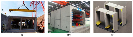
Figure 1.
Construction process classification. (a) The whole section of the full prefabricated; (b) Split components of the full prefabricated; (c) Mixed prefabricated.

Table 1.
The specific characteristics of each classification.
This project is based on a research background of a cast-in-place underground comprehensive utility tunnel project in Qianhai, Shenzhen. However, this project has very strict requirements for the construction schedule and on-site transportation and hoisting. Through extensive research, it has been found that the existing prefabricated comprehensive utility tunnel forms are not suitable for the smooth completion of this project in terms of construction conditions and assembly rate. Therefore, based on the site conditions of this project, the research team has designed a brand-new prefabricated and assembled concrete comprehensive utility tunnel. While meeting the construction requirements of this project, it is hoped that it can promote the standardized, industrialized, and factory-based construction of urban underground comprehensive utility tunnels in China, and respond to the policy call for green, low-carbon, and energy-saving prefabricated buildings. Compared with other forms of research, this new type of prefabricated and assembled comprehensive utility tunnels has further improvements in terms of construction assembly rate, lightweight hoisting, and construction environmental protection.
Based on the standard cross section of the cast-in-place underground comprehensive utility tunnel, the research team has designed a new type of prefabricated and assembled utility tunnel using mortise and tenon joints and prefabricated composite slabs. By constructing components and hoisting, the construction of a full-scale model has been completed. Mechanical loading tests and comparative analysis using ABAQUS finite element models have been conducted, and the results show that the prefabricated and assembled integral utility tunnel has a high safety reserve and can meet the engineering design requirements.
2. New Design of Assembled Integral Utility Tunnel
2.1. Project Overview
This design is based on the research background of the underground utility tunnel project in Qianhai, Shenzhen. The original cast-in-place utility tunnel standard section was taken as the research object, and an assembled integral design study was conducted based on this. The double-chamber standard section dimensions of the original cast-in-place utility tunnel are shown in Figure 2.
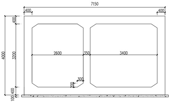
Figure 2.
The original cast-in-place utility tunnel (Units: mm).
2.2. Division of Assembled Components
The new assembled integral utility tunnel adopts prefabricated composite slabs, and the walls and bases are connected by mortise and tenon joints, while the bases are connected by a post-pouring belt. The schematic diagram of the component division of the assembled integral utility tunnel is shown in Figure 3.
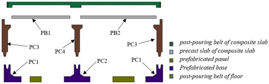
Figure 3.
The component division of the assembled integral utility tunnel.
The structural reinforcement diagram shows that the prefabricated assembled integral underground utility tunnel is composed of 8 prefabricated components, which are uniformly prefabricated with C40 concrete. Calculated based on the concrete density of 2500 kg/m3, the weight of each prefabricated module is shown in Table 2 below, with a width of 4 m as the unit:
Table 2.
The weight of each component.
As shown in Figure 4, the heaviest PC2 component can be easily lifted by a light-duty crane.
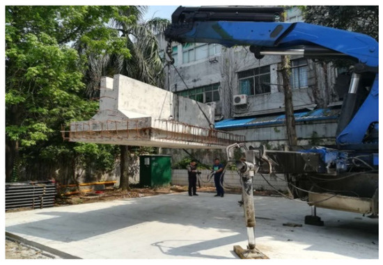
Figure 4.
PC2 component was lifted by a light-duty crane.
2.3. Structural Design
Based on the analysis of the original cast-in-place structure’s stress performance and section verification, the overall structural calculation and design of the assembled integral utility tunnel structure were carried out. The design and calculation of prefabricated components, key joints such as mortise and tenon joints, cow leg connections, and composite slabs were also conducted. Considering the on-site construction conditions, the final structural design schematic of the cross-section of the assembled integral utility tunnel was formed, as shown in Figure 5.
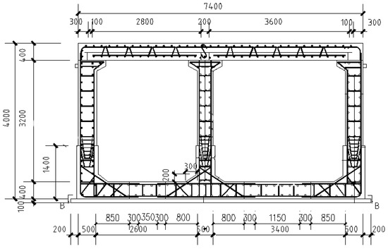
Figure 5.
Schematic diagram of structural design (Units: mm).
2.4. Simulation Analysis
According to the site investigation conditions, the base of the comprehensive utility tunnel is located below the original ground level and can utilize the natural foundation, including clay, medium sand, sandy clay, and mixed granite layers as the load-bearing layer. Above the original ground level, compacted fill soil is required as the load-bearing layer. The fill soil needs to be compacted in layers according to the design requirements, and it should be tested to ensure that it meets the design requirements before serving as the load-bearing layer. During construction, over-excavation can be used to solve the problem of crossing rock layers in settlement joint sections. After backfilling with graded sand and gravel (compaction coefficient greater than 0.96), the construction of the superstructure can be carried out. A raft foundation can be used for the base.
In practical engineering applications, the underground utility tunnel is subjected to loads on all sides. The top is subjected to the upper soil cover and live loads, while the left and right sides experience uneven soil pressures. The bottom plate is equipped with springs with the same stiffness as the soil layers. The simplified full-scale model under loading conditions is shown in Figure 6.
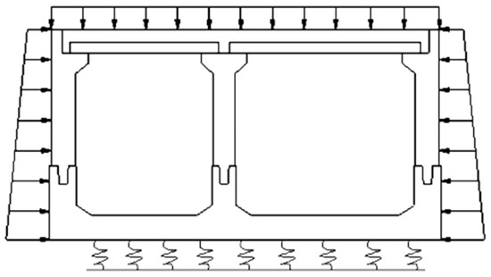
Figure 6.
Model Load Schematic.
To analyze the internal forces and displacements of the assembled integral utility tunnel under various design loads, the ABAQUS software was used for modeling and analysis [23,24]. The concrete strength in this model is set to C40, and the damage is represented using the built-in plastic damage model in the software, which combines isotropic elastic damage and compression-tension theory to represent the nonlinear characteristics of concrete. The contact between the utility tunnel components is simulated using ABAQUS/Standard, with a surface-to-surface discretization approach and finite sliding formulation. The frictional behavior in the tangential direction is governed by a “penalty” method, while the normal behavior is represented using hard contact. See Figure 7 for reference. The prefabricated components are not bound together, allowing for separation. The coupling between the steel reinforcement and concrete is implemented using embedded regions, with a rounding error coefficient of 1 × 10⁻⁶ and an external percentage tolerance of 0.05.
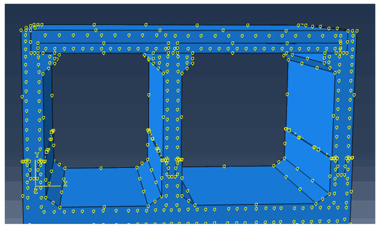
Figure 7.
Finite element modeling.
In the modeling process, the concrete is represented by C3D8R reduced-integration, hourglass-controlled eight-node linear hexahedral elements, with mesh refinement employed to address the “hourglass mode”. The steel reinforcement model includes horizontal reinforcement, longitudinal reinforcement, and corner reinforcement, which are calculated using T3D2 two-node linear three-dimensional truss elements [25]. To avoid the “hourglass phenomenon” and facilitate the observation of certain node positions, measures such as mesh refinement and striving for uniform mesh division are taken. The mesh size for concrete is set to 0.2 m, while the mesh size for steel reinforcement is set to 0.1 m. The assembled comprehensive utility tunnel model consists of 68,737 concrete elements and 74,625 concrete nodes, as well as 23,542 steel reinforcement elements and 24,678 steel reinforcement nodes. The division mesh diagram of the overall utility tunnel model can be seen in Figure 8.
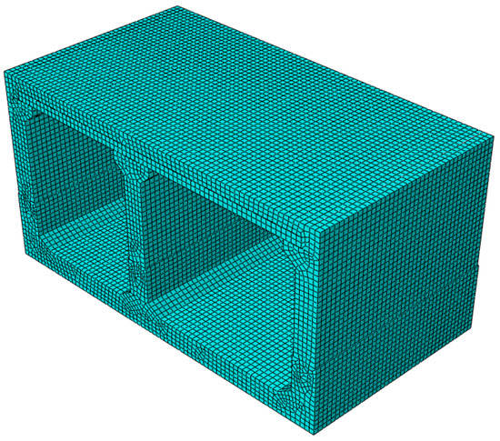
Figure 8.
Mesh configuration.
In practical engineering applications, the underground utility tunnel is subjected to loads on all sides, with uniform pressure at the top and uneven soil pressures on the left and right sides. The boundary conditions and interactions are shown in Figure 9.
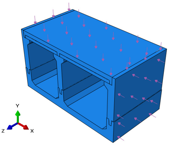
Figure 9.
Boundary conditions and interactions.
The results include displacement, stress, principal stress, and steel stress obtained through the finite element analysis as shown in Figure 10.
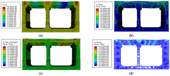
Figure 10.
The results of finite element analysis: (a) displacement, (b) stress, (c) principal stress, and (d) steel stress.
3. Full-Scale Model Test
3.1. Full-Scale Model Fabrication
To study the mechanical properties, such as bearing capacity and internal force distribution, as well as the structural characteristics of overall deformation, internal force distribution, and crack development of the new assembled integral culvert, and to evaluate the overall performance of the culvert and verify whether the mortise and tenon joints and other connecting nodes meet normal use requirements, a full-scale model test was conducted on a segment of the double-chamber assembled integral culvert.
The full-scale model components were manufactured in the factory according to the design drawings, including eight prefabricated modules, such as three base plates, two side plates, one middle plate, and two overlay plates.
Before hoisting, the size and weight of each component were determined, and hoisting exercises were conducted using a small indoor model to develop a suitable hoisting and transportation plan. Finally, the model was hoisted and formed, as shown in Figure 11.
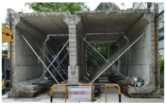
Figure 11.
Full-size model hoisting completed drawing.
The full-scale model was later uniformly cast with C40 concrete, and the overlay top plate and post-pouring base plate were completed. The full-scale model was 7.4 m wide, 4.0 m high, and 4.0 m long.
3.2. Test Loading Preparation
In actual field conditions, the lateral surface load that increases with depth cannot be fully simulated. In order to satisfy the force equivalence between the concentrated load in the test and the uniformly distributed load in real-life conditions as much as possible, the loading method was designed using the principle of equivalence to convert the real uniformly distributed load into a concentrated load with a similar bending moment diagram under two different load conditions.
The on-site loading design was to use a hydraulic jack to pull steel strands under the second-level distribution beam to apply force to the overlay top plate, as shown in Figure 12a. The test loading procedure is listed in Table 3: first, from the initial state, gradually load in five stages to the load standard combination value, then continue to load in two stages to the load design value, and finally, load in five stages to the strand fracture.
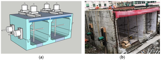
Figure 12.
(a) Schematic diagram of the test loading device; (b) Field test loading arrangement.
Table 3.
Test loading procedure.
The top plate and side walls of both compartments were loaded using 300-ton hydraulic jacks, with a total of 8 jacks placed, controlled by a CNC device to regulate the loading rate and load size. In actual operation, in order to reduce local pressure effects, two 3 cm thick Q235 steel plates with dimensions of 1 m × 1 m and 0.6 m × 0.6 m were used as steel pads on the top plate instead of a secondary distribution beam. The testing device included loading devices for the top plate and side walls, as well as a data acquisition system. The layout diagram of the loading device on site can be seen in Figure 12b.
3.3. Measurement and Equipment
The main measuring instruments and equipment used in the test include strain gauges for steel bars and concrete, digital display micrometers with signal, electronic crack width testers, and data acquisition instruments [26]. All strain and stress data can be collected through a strain testing and analysis system. Multi-bridge static testing can be conducted according to the corresponding testing circuit. Displacement data is read by the micrometer and load is read by the sensor.
4. Test Phenomena and Results
4.1. Cracks
After loading the top plate to the standard combination value and design combination value, continuous loading was carried out for 30 min, and crack observations were made. It was found that when the load was increased to the standard combination value, no microcracks were found at the bottom of the top plate’s prefabricated slab. When loaded to the design combination value, slight cracks appeared at the longitudinal side wall tenon connection, and several hard-to-distinguish microcracks were found in the support area of the outer wall’s leg. When loaded to the final stage, the smallest crack width was 0.02 mm and the largest was 0.17 mm, with several cracks around 0.09 mm. The distribution of cracks in the key parts of the utility tunnel under the final load is shown in Figure 13, and the cracks in the remaining parts are not yet obvious. These surface cracks have little effect on the mechanical and waterproof performance of the utility tunnel.
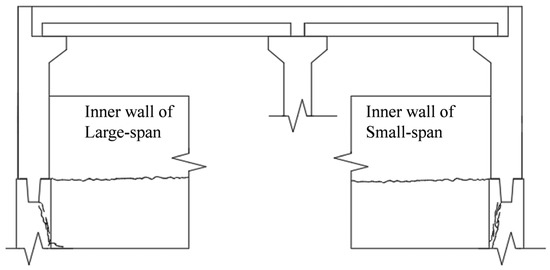
Figure 13.
Distribution of cracks under the final load.
4.2. Deformation
The deformation data of each part measured can be displayed on a comprehensive displacement diagram of the assembled utility tunnel, as shown in Figure 14. The black box line in the figure represents the actual boundary size of the utility tunnel, and the deflection deformation at the corresponding position represents the deflection change trend. The change in displacement of the large compartment roof of the utility tunnel is the largest, and the outer walsl of the small and large compartments tend to move inward. As shown in the figure, the displacement of the large compartment’s side wall is greater than that of the small compartment.
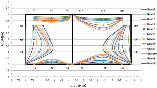
Figure 14.
Loading deformation curve.
With the mid-support line as the boundary, the clear span of the small warehouse roof is 2800 mm, and that of the large warehouse is 3600 mm. As the load gradually increases, the displacement of the large warehouse roof increases faster than that of the small warehouse, and ultimately, the displacement of the large warehouse is greater than that of the small warehouse. When loaded to the design value, the maximum deflection of the large warehouse roof is only about 1.075 mm, and when loaded to the final state, the displacement of the large warehouse roof is only 1.46 mm, which meets the requirement of less than 2 mm in the specification. The deformation of the small warehouse roof is only about 0.8 mm, which is about 1/3500 of the clear span of the small warehouse. The small deformation of the plate indicates that the comprehensive culvert with a composite roof has strong overall integrity and good load-bearing performance.
When the composite roof is loaded to the final state, the maximum deflection of the composite floor occurs at the mid-span of the roof, which is only 1.465 mm, far from the limit value of the specification for failure (taking the clear span as 3600 mm), indicating that the stiffness of the roof is large enough, and there is sufficient bearing capacity for further optimization of the design.
4.3. Strain and Internal Force Analysis
The composite slab was used for the utility tunnel roof, and the loading test mainly measured the stress-strain of the control sections, such as the continuous plate span and the support section under monotonic load; the distribution of the reinforcement and concrete strain measurement points are shown in Figure 15. The stress—strain relationship of the floor section was analyzed to investigate the force performance and synergistic working performance of the top slab of this design [27,28].
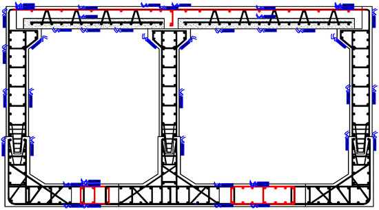
Figure 15.
Distribution of strain measurement points.
From the load—strain curve of the composite board in Figure 16a, it can be seen that the strain of the mid-span section develops slowly before reaching the standard combined load value, with a reinforcement strain increment of 16.11 με at the support. The average increment for the mid-span of the large warehouse is 14.75 με, and the average increment for the steel reinforcement strain of the entire top plate under the standard combined load is 13.04 με. After reaching the design load, the steel reinforcement strain develops rapidly, with an average strain increment of 25.55 με, indicating that the composite floor undergoes plastic deformation after reaching the design load.
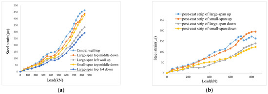
Figure 16.
Strain diagram of steel: (a) roof plate (b) bottom plate.
From the load—strain curves of the composite board at the mid-span and support positions, it can be seen that the development trend of the steel reinforcement load—strain curve and of the concrete load—strain curve at the mid-span during monotonic loading is not significantly different.
The final load value is 837 kN, which is 1.47 times the design combined load value. At this point, the maximum tensile strain of the steel reinforcement is 463 με, and the corresponding compressive strain of the concrete at the section is 423 με. This indicates that the composite floor exhibits good bearing capacity and overall performance until the end of the loading.
As shown in Figure 16b, the strain of the upper and lower layers of reinforcement at the bottom plate of the two-span is not very large, and the trend of change is also slow. The analysis revealed the following reasons: on the one hand, it may be due to the steel strand tensioning process of the laminated top plate due to the elimination of pre-pressure, which slows down the stressing process of the reinforcement, and on the other hand, because the reinforcement rate of the post-cast zone is too large, the reinforcement is too thick, and the position and it may have a front and rear misalignment.
As shown in Figure 17, the neutral axis position of the section is not in the middle position but above the composite surface. During use, the height of the compression zone is smaller than the height of the post-pouring layer, and the prefabricated part bears only tension, which is consistent with the theoretical results.
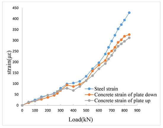
Figure 17.
Strain distribution in the composite board of small-span.
The concrete strain diagram of the key positions on the top plate can be seen in Figure 18, showing that the bending moments at the middle and both ends are larger. Until the final loading, the load-bearing supports at both ends of the two plates did not experience shear failure. From the figure, it can be seen that the bending moment is the largest in the middle of the two-span, and the concrete strain at each position shows a linear trend. At this time, the plate is still in the elastic stage, indicating that there is still excess bearing capacity. The concrete at the end supports of the plate also meets the normal use requirements without shear failure, and the entire corridor did not experience bending failure.
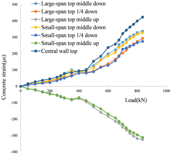
Figure 18.
Concrete strain in important parts of the roof.
4.4. Analysis of Load-Deflection Comparison
The full-scale model test results are compared with the finite element simulation results of the deflection values of the top plate. As shown in Table 4, the experimental deflection values of the overlapped top plate are larger than the finite element simulation results in each stage, and the relative difference between the two is maintained at about 0.85.
Table 4.
Comparison of mid-span deflection values of the top plate.
The measured data is formed into a curve diagram as shown in Figure 19a,b. The test results are lower than the finite element simulation results.
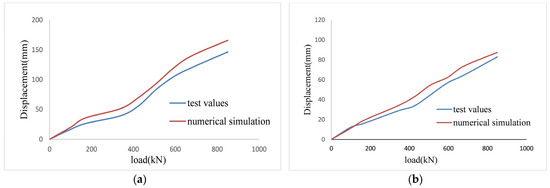
Figure 19.
The mid-span load—deflection curve: (a) large-span (b) small-span.
5. Discussion and Prospect
An urban underground comprehensive utility tunnel is an important approach to address the chaotic situation of “road zippers”, “spiderweb-like” aerial cables, and garbage surrounding cities. It helps alleviate the shortage of urban land, improve urban functionality, and enhance the overall capacity of cities. Currently, the construction of urban utility tunnels is being vigorously promoted nationwide. Nearly a hundred cities in China are either underway or about to initiate utility tunnel projects. At the same time, the country strongly advocates for industrialized construction and green buildings. Assembled integral utility tunnels can effectively compensate for the shortcomings of traditional utility tunnel construction techniques. It is in this context that this paper proposes a new method for constructing a prefabricated assembled concrete utility tunnel.
Based on the construction project of an underground comprehensive utility tunnel in Shenzhen, the components and structural design of the new assembled integral utility tunnel were developed on the basis of the existing cast-in-place utility tunnel design. The utility tunnel consists of several prefabricated components, which are factory-produced, transported to the construction site, and assembled through lifting operations to form the assembled integral utility tunnel. Compared with other forms of utility tunnels, it has the following advantages:
- The assembly rate of this prefabricated assembled concrete utility tunnel is relatively higher, with lifting and assembly processes completed on-site. There is less on-site wet cast-in-place work, which can improve construction efficiency and shorten the construction period.
- The components of the prefabricated assembled concrete utility tunnel are relatively small. According to the calculation results of Section 2.2, the heaviest component weighs only 14.2 tons, easily meeting the transportation and lifting requirements during on-site construction.
- The main components of the utility tunnel are produced in standardized industrial factories using assembly line production methods. They are produced according to uniform standards, reducing dimensional errors and ensuring the quality of the components.
- The main structure of the utility tunnel is completed outside the construction site, enabling fast on-site assembly. After partial installation, backfilling and burial can be carried out, reducing the impact on the surrounding environment and the daily life and transportation of citizens.
To verify the actual load-bearing performance of the utility tunnel, mechanical loading tests were designed and conducted on a full-scale utility tunnel. The actual load-bearing conditions of the underground utility tunnel were simulated using the finite element software ABAQUS, and the results were compared and analyzed with the experimental values. Based on the test and comparative analysis results, it can be observed that the new assembled integral utility tunnel exhibits good deformation control capability and overall load-bearing performance during the loading process, meeting the design requirements.
With the large-scale promotion and application of comprehensive utility tunnels, there is still a long way to go in the research of utility tunnels. This paper only focused on the study of the load-bearing performance and deformation control of the new assembled utility tunnel. Further research can be conducted in the following areas: study of important nodes in the new assembled integral utility tunnel, investigation of the load-bearing performance of individual components, testing of waterproof performance, and analysis of the influence of foundation settlement on connection performance, among others.
6. Conclusions
Based on the cast-in-place utility tunnel, this paper designs a new type of assembled integral utility tunnel and creates a full-scale model of a double-chamber assembled integral utility tunnel segment. Static load tests and finite element analysis are conducted to compare and study the new assembled integral utility tunnel model. Based on the test results and mechanical analysis, the following conclusions can be drawn:
- No cracks were found when the utility tunnel was loaded up to the load standard value. When loaded to the design value, slight cracks appeared along the tenon joints of the side walls. No cracks were observed on the roof slab under the ultimate load.
- As the load increased, the deformation of the composite continuous slab gradually increased. However, the deformation control capability remained within the design requirements, and no significant local damage occurred. When the roof slab was loaded to the design value, the maximum displacement at the mid-span of the large chamber was 1.075 mm. When loaded to the ultimate load, the maximum displacement at the mid-span of the large chamber was 1.465 mm.
- From the strain analysis results, it can be observed that the composite continuous slab underwent plastic deformation after the design load, but its overall load-bearing performance remained good, and no failure occurred. The strain analysis results at the tenon support indicate that the concrete strain changed linearly at various locations. The tenon support exhibited good overall working performance during the loading process and did not experience shear failure.
- Before reaching the standard load value, the strain development at the mid-span section was slow. After reaching the design load, the steel strain developed rapidly, with an average strain increment of 25.55 με. At the final load value, the maximum tensile strain of the steel was 463 με. The load-bearing supports at both ends of the two slabs did not experience shear failure, and the concrete strain changed linearly at various locations.
- Under the ultimate load, the composite continuous slab did not undergo failure and remained in the elastic stage. This indicates that it had a certain amount of load-bearing capacity surplus and the potential for further optimization of the design.
Based on the experimental and comparative analysis results, it can be concluded that the new assembled integral utility tunnel exhibited good overall load-bearing performance and deformation control capability under monotonic loading. The adoption of tenon connections and composite assembly design demonstrated good load-bearing performance and reliability, meeting the design requirements. It has promising prospects for practical applications in engineering.
Author Contributions
Conceptualization, J.Z. and Y.Z.; methodology, Y.Z.; software, Y.Z., C.P. and Y.L.; validation, Y.Z., C.P., Y.L., Z.Z. and Z.C.; investigation, Y.Z.; data curation, C.P.; writing—original draft, Y.Z.; writing—review and editing, C.P.; supervision, J.Z. and A.Z.; project administration, Y.Z. and A.Z.; funding acquisition, J.Z. and A.Z. All authors have read and agreed to the published version of the manuscript.
Funding
This research was funded by the Guangdong Key Areas R&D Program Projects, China (grant number: 2020B0101130005), and by Research Project of Guangdong Power Grid Co. (grant numbers: 031000QQ00220012).
Data Availability Statement
The data used to support the findings of this study are available upon request from the corresponding author.
Conflicts of Interest
The authors declare that they have no known competing interest that could have appeared to influence the work reported in the paper.
References
- Hunt, D.V.L.; Nash, D.; Rogers, C.D.F. Sustainable utility placement via Multi-Utility tunnel. Tunn. Undergr. Space Technol. 2014, 39, 15–26. [Google Scholar] [CrossRef]
- Canto-Perello, J.; Curiel-Esparza, J. Human factors engineering in utility tunnel design. Tunn. Undergr. Space Technol. 2001, 16, 211–215. [Google Scholar] [CrossRef]
- Cano-Hurtado, J.J.; Canto-Perello, J. Sustainable development of urban underground space for utilities. Tunn. Undergr. Space Technol. 1999, 14, 335–340. [Google Scholar] [CrossRef]
- Ding, X.M.; Zhang, J.C.; Xu, Y.; Zhu, C. Discussion on Construction and Management of the Common Trench in Guangzhou University Town. Chin. J. Undergr. Space Eng. 2010, 6, 1385–1389+1469. [Google Scholar]
- Luo, Y.; Alaghbandrad, A.; Genger, T.K.; Hammad, A. History and recent development of multi-purpose utility tunnel. Tunn. Undergr. Space Technol. 2020, 103, 103511. [Google Scholar] [CrossRef]
- Canto-Perello, J.; Curiel-Esparza, J.; Calvo, V. Criticality and threat analysis on utility tunnel for planning security policies of utilities in urban underground space. Expert Syst. Appl. 2013, 40, 4707–4714. [Google Scholar] [CrossRef]
- Yang, C.; Peng, F.L. Discussion on the development of underground utility tunnel in China. Procedia Eng. 2016, 165, 540–548. [Google Scholar] [CrossRef]
- Wang, T.Y.; Tan, L.X.; Xie, S.Y.; Ma, B.S. Development and applications of common utility tunnel in China. Tunn. Undergr. Space Technol. 2018, 76, 92–106. [Google Scholar] [CrossRef]
- Sun, D.W.; Liu, C.Y.; Wang, Y.Y.; Xia, Q.L.; Liu, F.Q. Static performance of a new type of corrugated steel-concrete composite shell under mid-span loading. Structures 2022, 37, 109–124. [Google Scholar] [CrossRef]
- Wu, X.G.; Nie, C.H.; Li, D.; Qiu, F.Q.; Tang, Y.C. Structural Response of a Prefabricated Utility Tunnel Subject to a Reverse Fault. Buildings 2022, 12, 1086. [Google Scholar] [CrossRef]
- Hu, X.; Xue, W. Experimental Study of Mechanical Properties of PPMT. China Civ. Eng. J. 2010, 43, 29–37. [Google Scholar]
- Li, L.; Luo, D.; Liu, L.; Li, Y.; Liu, Y.; Li, J. Research on the waterproof design of the prefabricated assembled utility tunnel joints. IOP Conf. Ser. Mater. Sci. Eng. 2018, 439, 042054. [Google Scholar] [CrossRef]
- Fang, Z.; Jin, Y.; Guo, F.N.; Zhang, D.F.; Mo, C.Q.; Huang, S. Experimental Research on Mechanical Properties of Assembled Monolithic Concrete Utility tunnel. Ind. Constr. 2021, 51, 47–56. [Google Scholar]
- Li, Z.; Luo, Q.Y.; Zhou, R. Experimental research on seismic response of split-type prefabricated utility tunnel through shaking table tests. Earthq. Eng. Struct. Dyn. 2022, 51, 2880–2903. [Google Scholar] [CrossRef]
- Lin, Z.; Guo, C.; Ni, P.; Cao, D.; Huang, L.; Guo, Z.; Dong, P. Experimental and numerical investigations into leakage behaviour of a novel prefabricated utility tunnel. Tunn. Undergr. Space Technol. 2020, 104, 103529. [Google Scholar] [CrossRef]
- Wu, S.W.; Zhao, G.Y.; Zhu, L.; Liu, W.; Duan, S.J. Experimental and numerical investigation on the cross-sectional mechanical behavior of prefabricated multi-cabin RC utility tunnel. Structures 2022, 42, 466–479. [Google Scholar] [CrossRef]
- Xiao, Y.G.; Zhang, J.B.; Cao, J.; Li, C.H. Prefabricated Urban Underground Utility tunnel: A Case Study on Mechanical Behaviour with Strain Monitoring and Numerical Simulation. Adv. Mater. Sci. Eng. 2021, 2021, 5534526. [Google Scholar] [CrossRef]
- Huang, B.T.; Zhu, J.X.; Weng, K.F.; Huang, J.Q.; Dai, J.G. Prefabricated UHPC-concrete-ECC underground utility tunnel reinforced by perforated steel plate: Experimental and numerical investigations. Case Stud. Constr. Mat. 2022, 16, e00856. [Google Scholar] [CrossRef]
- Wang, Z.S.; Wang, Y.Y.; Huang, W.K.; Shan, H.W.; Zhu, L. Research on Natural Foundation Bearing Capacity and Foundation Pit Settlement of Prefabricated Utility Tunnel. Adv. Civ. Eng. 2022, 2022, 5361199. [Google Scholar] [CrossRef]
- Kuang, Y.C.; Peng, Z.W.; Yang, J.H.; Zhou, M.M.; He, C.; Liu, Y.H.; Mo, X.F.; Song, Z.X. Physical and Numerical Simulations on Mechanical Properties of a Prefabricated Underground Utility Tunnel. Materials 2022, 15, 2276. [Google Scholar] [CrossRef]
- Wang, Q.H.; Gong, G.B.; Hao, J.L.; Bao, Y.F. Numerical Investigation of Prefabricated Utility tunnel Composed of Composite Slabs with Spiral Stirrup-Constrained Connection Based on Damage Mechanics. Materials 2022, 15, 6320. [Google Scholar] [CrossRef] [PubMed]
- Shan, H.W.; Sun, M.; Xian, J.P.; Zhu, L.; Yu, H. Mechanical Properties of Prefabricated Assembly Utility Tunnel Construction and Field Full-scale Test Study in the Process of Erection of Utility tunnel. Mod. Tunn. Technol. 2022, 59, 147–153. [Google Scholar]
- Gemi, L.; Alsdudi, M.; Aksoylu, C.; Yazman, Ş.; Özk, Y.O. Optimum amount of CFRP for strengthening shear deficient reinforced concrete beams. Steel Compos. Struct. 2022, 43, 735–757. [Google Scholar] [CrossRef]
- Özkılıç, Y.O.; Aksoylu, C.; Yazman, Ş.; Gemi, L.; Arslan, M.H. Behavior of CFRP-strengthened RC beams with circular web openings in shear zones: Numerical study. Structures 2022, 41, 1369–1389. [Google Scholar] [CrossRef]
- Özkılıç, Y.O.; Aksoylu, C.; Arslan, M.H. Numerical evaluation of effects of shear span, stirrup spacing and angle of stirrup on reinforced concrete beam behaviour. Struct. Eng. Mech. 2021, 79, 309–326. [Google Scholar] [CrossRef]
- Yuan, C.; Chen, W.S.; Pham, T.M.; Hao, H.; Chen, L.; Wang, J. Experimental and analytical study of flexural behaviour of BFRP sheets strengthened RC beams with new epoxy anchors. Eng. Struct. 2021, 241, 112441. [Google Scholar] [CrossRef]
- Ivashenko, Y.; Ferder, A. Experimental studies on the impacts of strain and loading modes on the formation of concrete “stress-strain” relations. Constr. Build. Mater. 2019, 209, 234–239. [Google Scholar] [CrossRef]
- Jiang, L.J.; Bai, G.L. Experimental Study on Cumulative Damage Behavior of Steel-Reinforced Concrete Columns. Adv. Civ. Eng. 2020, 2020, 5281725. [Google Scholar] [CrossRef]


Disclaimer/Publisher’s Note: The statements, opinions and data contained in all publications are solely those of the individual author(s) and contributor(s) and not of MDPI and/or the editor(s). MDPI and/or the editor(s) disclaim responsibility for any injury to people or property resulting from any ideas, methods, instructions or products referred to in the content. |
© 2023 by the authors. Licensee MDPI, Basel, Switzerland. This article is an open access article distributed under the terms and conditions of the Creative Commons Attribution (CC BY) license (https://creativecommons.org/licenses/by/4.0/).