Article

Anchor Behavior of One-Side Bolt with Flip-Top Collapsible Washer

1
Shandong Electric Power Engineering Consulting Institute Corp., Ltd., Jinan 250013, China
2
School of Mechanics and Civil Engineering, China University of Mining and Technology, Xuzhou 221116, China
3
School of Architecture and Construction, Jiangsu Vocational Institute of Architectural Technology, Xuzhou 221116, China
*
Author to whom correspondence should be addressed.
Buildings 2023, 13(6), 1571; https://doi.org/10.3390/buildings13061571
Submission received: 29 April 2023 / Revised: 12 June 2023 / Accepted: 13 June 2023 / Published: 20 June 2023

Abstract

:
With the development of blind bolts that can be installed from the outer side of a section, the application of steel pipe hollow sections in prefabricated structures has become possible. The novel one-side bolt with a flip-top collapsible washer (FTW-OSB) is proposed, which can fold the washer at the end of the bolt to achieve a simple and efficient installation. Firstly, the components and installation process of the FTW-OSB are introduced. Additionally, axial tensile tests were carried out on three types of new bolts, and the failure mode, load–displacement curve, and ultimate capacity were analyzed. Based on this, the finite element model was verified, and through a series of finite element parameter analyses, the influence of washer size and construction, the friction coefficient, and the contact surface size on the new bolt were analyzed and optimized. The results show that the L-shaped washer can prevent washer rotation and has better anchoring performance than the I-shaped washer. The washer thickness, height, and upper contact surface size are the key factors affecting the anchoring performance of the FTW-OSB bolt. Among these factors, when the washer thickness increases from 0.1 d0 to 0.3 d0, the ultimate capacity and initial stiffness of the FTW-OSB bolt increase by 136.5% and 100.3%, respectively. The lower contact surface size and friction coefficient can be ignored. The failure model of the FTW-OSB is mainly washer shear failure and bolt tension failure. By effectively adjusting the washer thickness, side wall height, and upper contact surface size, shear failure of the washer can be avoided and an anchoring performance can be achieved that is the same as that of the same type of 10.9-grade ordinary high-strength bolt.

1. Introduction

The one-side bolt is a novel type of bolt that can be used for closed-off sections or structures such as walls [1]. It is generally installed using specific techniques or by modifying the structure of traditional high-strength bolts. It plays an important role in situations where conventional bolts cannot be fastened [2]. Several one-side fasteners have been developed abroad for connecting steel components, including Flowdrill [3,4] from Flowdrill BV in the Netherlands; one-sided bolts [5,6] from Ajax Fastener Company in Australia; BOM and HSBB [7] from Huck International in the United States; Ultra-Twist high-strength bolts from the United States [8]; holo-Bolt, RMH, and EHB bolts [9] from Lindapte in the United Kingdom; and Blind Bolt [10] from Blind Bolt Company. Two key issues in these blind bolts have been widely studied, namely the one-sided operating mechanism and the anchoring ability. Ajax Oneside [5,6] was found to be easily installed using a special wrench and a foldable washer. However, it was found that the flat washer was unstable under high load levels, especially for high-strength bolts with high pre-tension levels. Wang [11] reported on a blind bolt with a critical sliding washer, in which an improved slope washer was developed to address this issue. However, in terms of the anchoring capability of the one-side bolt’s washer, the one-side bolt [5,6] employs a flat washer with excessive thickness. The BOM, HSBB [7] bolts can only meet the performance requirements of the American standard A235 bolts, and it is not possible to apply pre-tensioning force during installation. In terms of the failure modes of one-side bolts under axial tension, Hollo-Bolt [9,11,12] experiences shear failure of the umbrella-shaped washer, resulting in lower bolt-bearing capacity, while [13] exhibits the failure mode of bolt fracture, failing to fully utilize the material properties of the bolt. Therefore, it is necessary to optimize the design of key components such as the one-side bolt washer, while ensuring convenient installation, in order to enhance the anchoring performance of one-side bolts.
Blind-bolt anchoring capacity is another hot research topic. Due to the differences in the anchor head and washer compared to regular high-strength bolts, the anchoring performance of blind bolts differs from that of regular high-strength bolts. Yeomans [14] and Elghazouli [15] found in their experiments that the anchoring capacity of Hollo bolts was lower than that of equivalent-grade regular bolts. K.A. Nakajima [16] conducted a series of experiments on the axial relaxation and fatigue of one-side high-strength bolts, as well as the post-fatigue anchorage, and found that the axial force relaxation and fatigue design curves of one-side high-strength bolts were similar to those of regular high-strength bolts. Agheshlui [17,18,19] conducted pull-out tests on three groups of single-side bolts to study their anchoring capacity, and found that the anchoring capacity of single-side bolts was comparable to that of standard high-strength bolts. Oktavianus et al. [20] studied the anchoring performance of double-headed blind bolts in circular hollow concrete column sections and proposed a theoretical model for estimating the anchoring strength and stiffness of bolts. Recently, Tilak et al. [21] reported the experimental results of the anchoring performance of double-headed blind bolts in square hollow concrete sections under cyclic loading. Zhang et al. [22] studied the force performance of TFOSB single-side bolts and found that the operating efficiency was greatly improved, but the ultimate tensile strength of the T-joints connected by TFOSB was reduced by 5.9% to 12.9% compared to traditional bolted connection joints. Furthermore, regarding the application of the finite element method in the deformation response of structural components, S. Gohari [23] and Quesada [24] have made advancements and applied them in the selection of material model parameters for the fracture simulation of aluminum plate components and sheet metal forming. However, there is limited research on the effects of contact between different components and element selection on the structural stiffness, strength, and other aspects under structural plastic deformation.
To address the complexities associated with construction and the substantial weakening of both the bolt and steel pipe in existing one-side bolt anchoring methods, this paper presents a novel blind bolt with a flip-top collapsible washer (FTW-OSB). This innovative bolt design facilitates convenient manufacturing and easy installation. Through experimental testing and finite element parameter optimization, the dimensional parameters of the profiled washer are fine-tuned to control the failure mode of the bolt, thus achieving anchoring performance comparable to high-strength bolts of similar caliber. The aim is to achieve a combination of convenient bolt installation and robust anchoring performance.

2. The Introduction of the FTW-OSB

As previously mentioned, the development of the novel blind bolt with a flip-top collapsible washer (FTW-OSB) aims to use the space behind the blind-bolt anchoring head to improve the anchoring ability of the flat washer. The conceptual design of the FTW-OSB is illustrated in Figure 1. The development approach involves modifying the bolt head of domestically produced high-strength bolts. The self-designed fixing plate and torsion spring are welded to the end of the bolt head using argon arc welding. The profiled washer is connected to the torsion spring through a steel strip. During installation, the profiled washer rebounds within the closed section under the torque of the spring, creating an anchoring end and enabling the one-sided operation of the bolt. The main components of the FTW-OSB include a high-strength bolt rod, fixing plate, torsion spring, profiled washer, steel strip, outer washer, and nut. The torsion spring is an improved version of the existing 180° torsion spring. As shown in Figure 2, the operating principle and process of the FTW-OSB for one-sided operation are as follows: Four profiled washers are fixed onto the octagonal fixing plate using torsion springs. The fixing plate is then welded to the top of the bolt head. The profiled washers are point-welded to the reinforcing bar and connected to the torsion springs as a whole. Before installation, the profiled washers are folded to the top of the bolt head. The foldable washer is designed to be smaller than the bolt hole after flipping, so the washer can easily enter the bolt hole together with the bolt head. When the washer and bolt head pass through the hole completely, the flip-foldable washer folds back to the bottom of the bolt head under the torsional force of the spring. By pulling the bolt rod backward, the washer tightly contacts the bolt head, achieving initial anchoring. Finally, a pretension load is applied by tightening the outer nut.
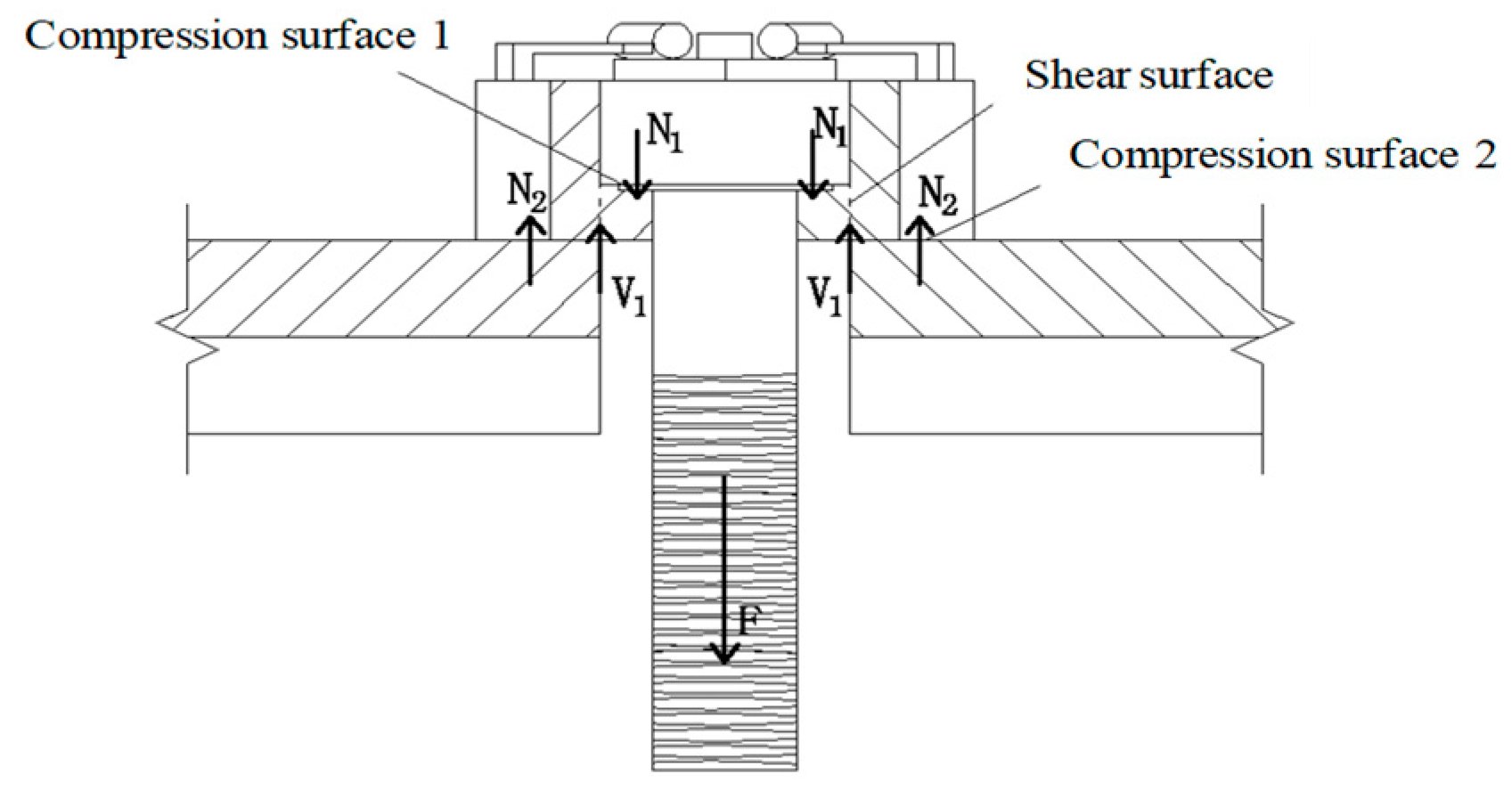
The anchor mechanism of the FTW-OSB is shown in Figure 3. It can be seen from Figure 3 that during the FTW-OSB working process, the profiled washer is subject to compression and shear. Specifically, when the bolt shank is subjected to tensile force (F), the compression surfaces 1 and 2 are, respectively, subjected to the pressure of the bolt head and the fixed plate (N1 and N2). The shearing surface inside the washer is subject to the shearing force (V1) of the bolt head and fixed plate. Furthermore, the anchoring performance of the flip-top collapsible washer has been improved compared to the flat washer used in the one-side bolt [5,6] and the umbrella-shaped washer used in the Hollo-Bolt [9].

3. Experimental Tests

3.1. Design of the Test Specimens and Material Properties

Nine specimens of FTW-OSB were designed considering two factors: bolt specifications and the thickness of the washer. According to [25], the thickness of the washer and the length of the bolt for normal high-strength bolts are considered. Due to the complexity of the profiled washer design, a washer thickness range of 0.1 d0 to 0.3 d0 was selected. To prevent local failure at the end of the bolt and slippage in the fixture during the tensile test, the length of the FTW-OSB was chosen as 150 mm. The diameter of the bolt was designed to be 10 mm larger than the diameter of the bolt, which was 26 mm, 30 mm, and 34 mm for M16, M20, and M24 bolt, respectively. The torsional spring and the steel strip were designed for the installation purpose, with diameters of 1 mm and 3 mm, and other labels and dimensions of test components are shown in Table 1. The material of the FTW-OSB was composed of 20 MnTiB alloy structural steel. Typical material properties such as elastic modulus, yield strength, and tensile strength of the specimens were obtained by conducting tests according to ASTM A370-18 standard [26] on a 100-ton electro-hydraulic servo universal testing machine, and the results are shown in Table 2.

3.2. Test Setup

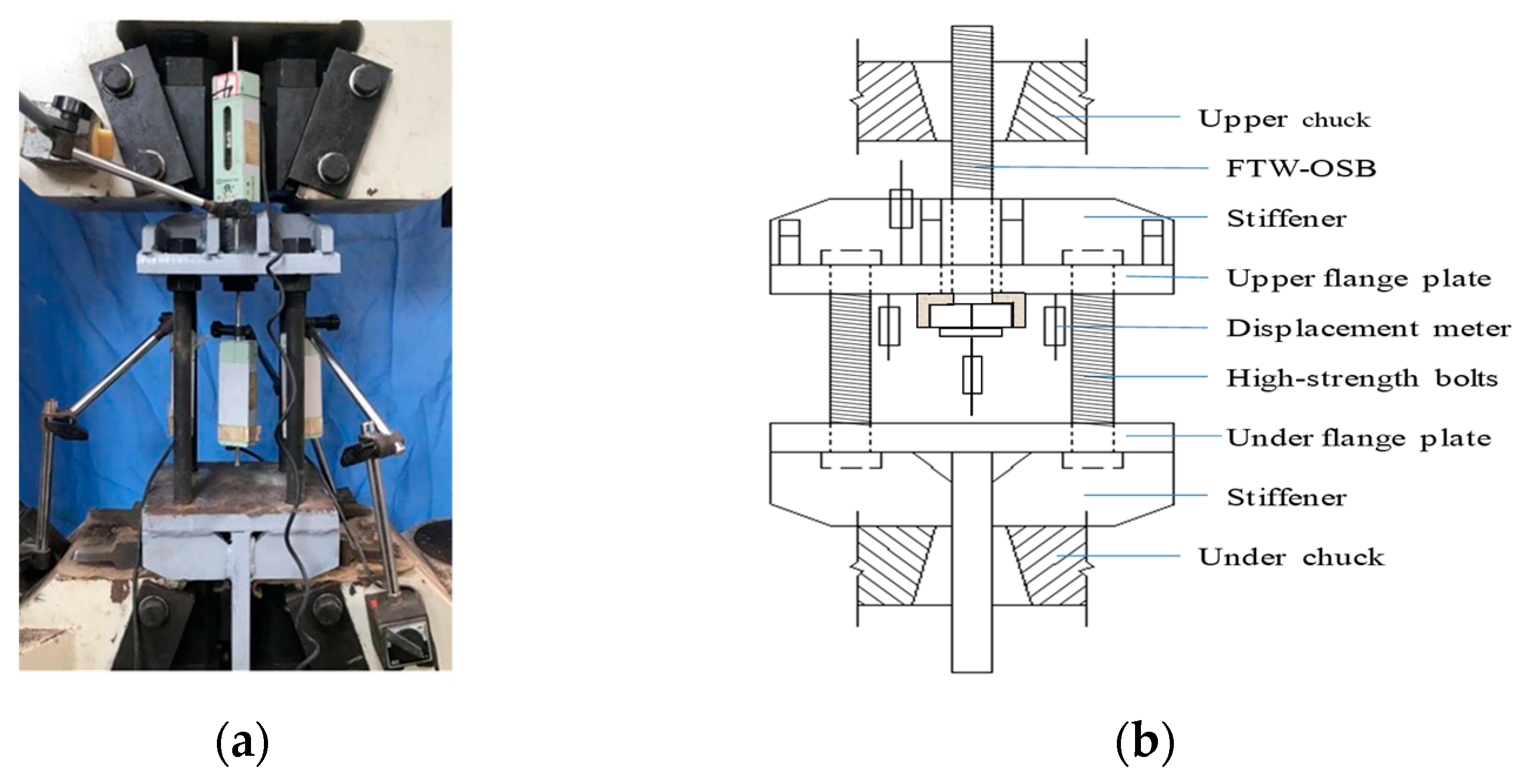
The anchoring test was conducted on a computer-controlled hydraulic servo universal testing machine with a model number of WAW-1000B and a capacity of 100 tons, as shown in Figure 4a. The anchoring test was conducted on a 100-ton hydraulic universal tensile machine, as shown in Figure 3. Two rigid anchor plates were fabricated and connected with 4 M20 high-strength bolts. Then, the lower anchor plate was fixed to the lower chuck of the tensile machine. One end of FTW-BB was fixed to the upper flange plate, and the other end was fixed to the upper chuck of the tensile machine. A stable and increasing load was applied on the top chuck of the machine until the specimen failed. The displacement variation of the specimens was measured using a linear variable displacement transducer (LVDT) with a total stroke of 50 mm. To obtain the relative displacement between the upper and lower flange plates, LVDTs 1 and 2 were arranged under the upper flange plate, while LVDT 3 was placed at the center point of the bolt head to measure the compressive displacement at the bolt head. LVDT 4 was used to measure the absolute displacement of the upper flange plate.

3.3. Test Phenomena and Typical Failure Modes

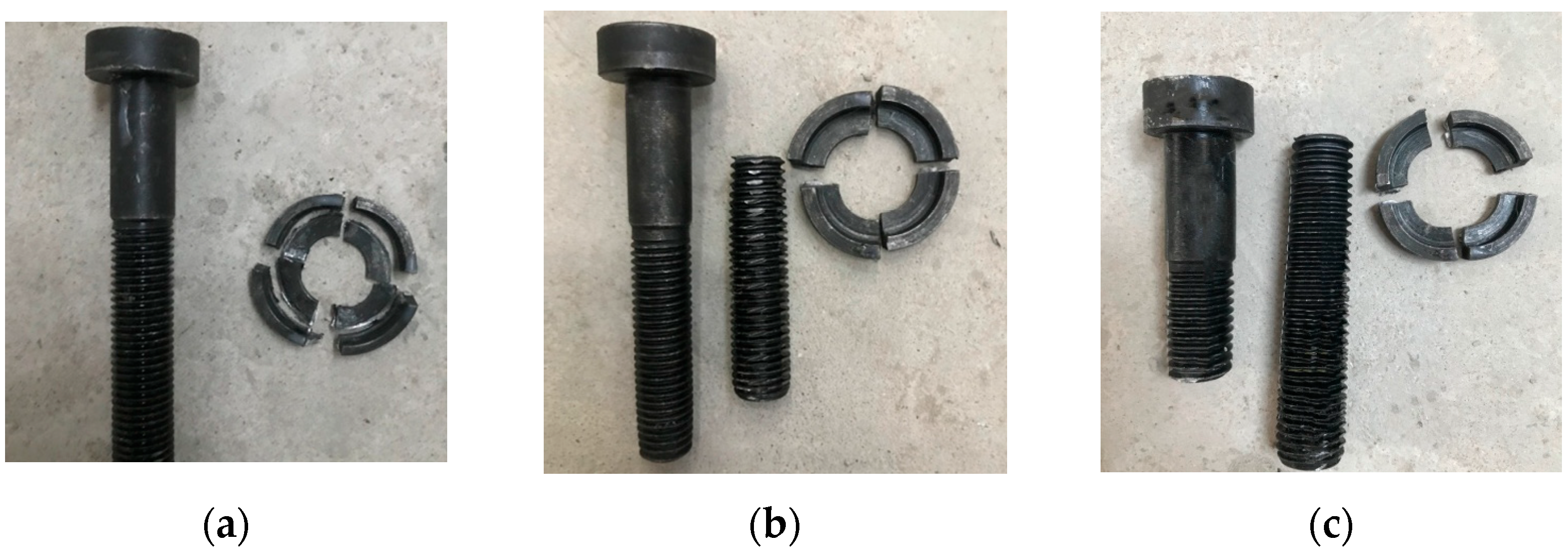
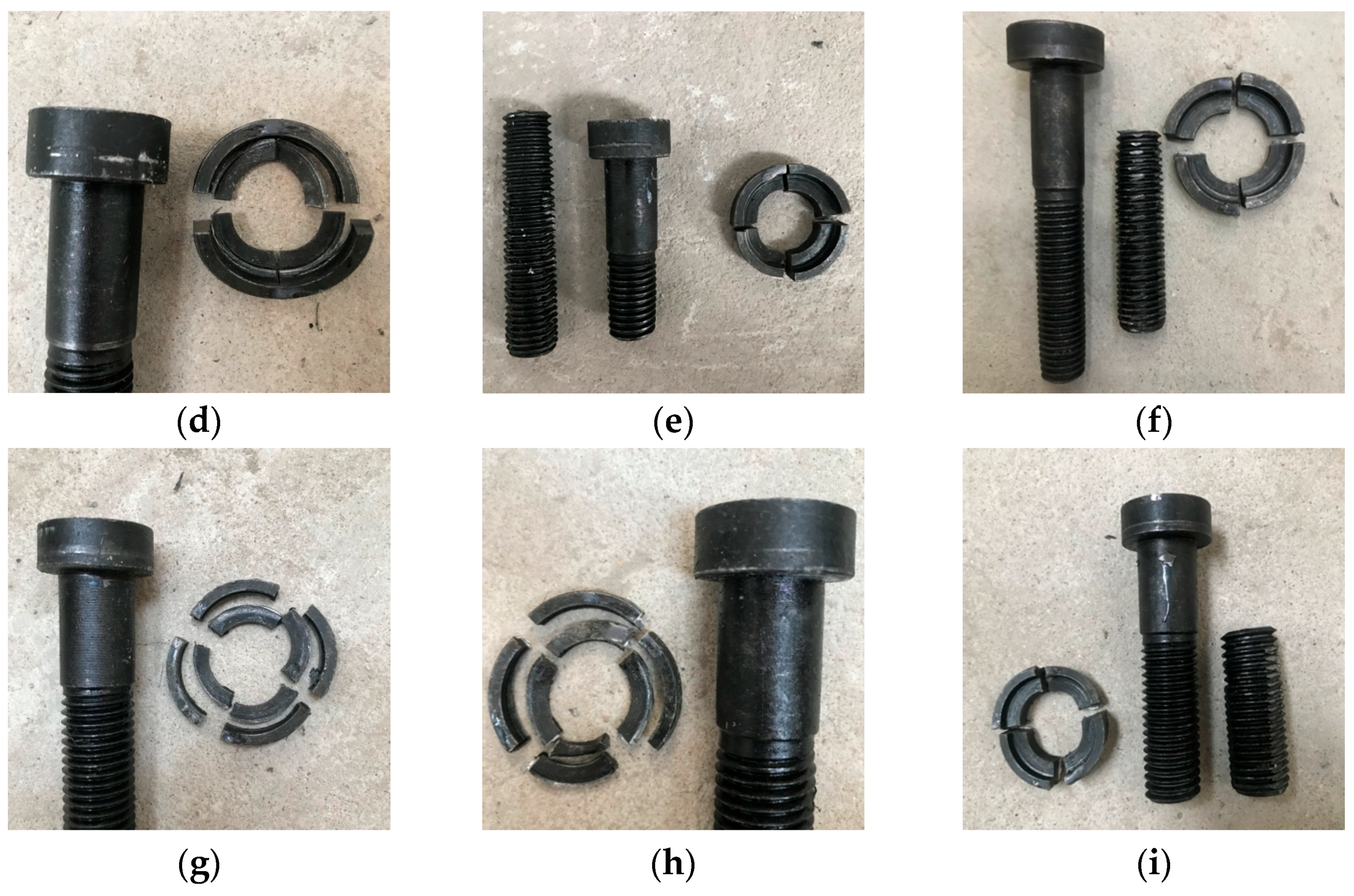
The failure modes of specimens are shown in Figure 5, which can be mainly classified into washer shear failure and bolt tensile failure. As shown in Figure 5a,d,g, when e = 0.1 d0, the washers of FTW-OSB in M16, M20, and M24 models were all sheared, but the bolt rods were not pulled apart, indicating that the bolts did not fully exert their bearing capacity. When e = 0.2 d0, the failure positions of M16 and M20 models were transferred from washer shear failure to bolt tensile failure, indicating that the bolt rods failed before the non-standard washer. However, the FTW-OSB of the M24 model was sheared, but the bolt rod was not pulled apart. When the washer thickness increased to 0.3 d0, all FTW-OSB bolts in M16, M20, and M24 models underwent bolt tensile failure, fully exerting the bearing capacity of the bolts. (Figure 5b,c,e,f,h,i).

3.4. Load–Displacement Curves and Anchor Strength

The load–displacement curves of the specimens are shown in Figure 6. The methods for obtaining the initial yield stiffness, yield capacity, and ultimate capacity are described in reference [27], and the test results are summarized in Table 3.
According to Figure 6 and Table 3, it can be observed that the initial stiffness and ultimate bearing capacity of FTW-OSB significantly increase with the increase in washer thickness. For instance, when the thickness of the washer increases from 0.1 d0 to 0.2 d0 and 0.3 d0, the tensile bearing capacity of the FTW-OSB of M20 increases by 134.0% and 136.5%, respectively, and the initial stiffness increases by 87.9% and 100.3%, respectively. For M16 and M20 bolts with e = 0.2 d0 and e = 0.3 d0, the bolt load–displacement curves are basically the same, but the bolt bearing capacity is slightly lower than the theoretical value due to machining errors, i.e., the actual diameter of the bolt is slightly smaller than the theoretical value. For M24 bolts, the load–displacement curves differ significantly when the washer thickness is 0.2 d0 and 0.3 d0, which is caused by the eccentric tension and shear stress acting on the bolt during loading. Furthermore, when the washer thickness is 0.1 d0, the washer undergoes brittle shear failure for all three types of bolt, and the bolt rod cannot be fully loaded and its bearing capacity cannot be fully utilized.

4. Finite Element Model and Validation

4.1. Finite Element Model

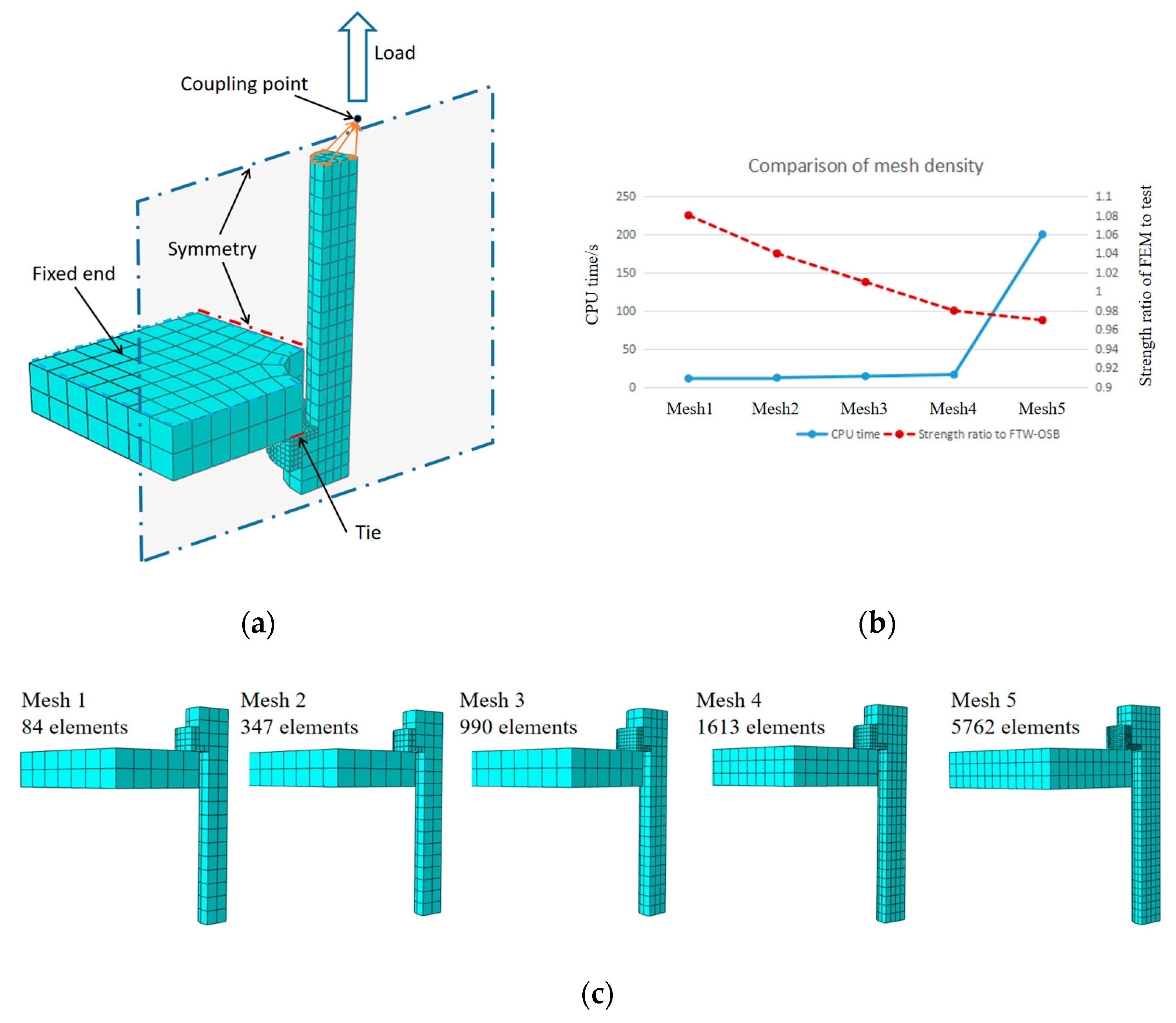
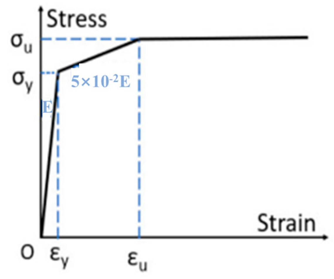
A finite element model of an anchored FTW-OSB was established using ABAQUS 6-14 software, as shown in Figure 7a. Based on the aforementioned working mechanism and failure mode of the FTW-OSB, it is evident that the tensile load-bearing capacity of the FTW-OSB is primarily controlled by the bolt and profiled washer. Therefore, the model simplifies the remaining structural components, such as the torsion spring and steel strip. Due to the symmetry of the model, a 1/4 solid model was established to reduce the calculation time and improve the calculation convergence. The bolt and washer were modeled using a multi-linear kinematic hardening constitutive model, considering the Von Mises yield criterion and related flow rules. The stress and strain relationship of steel is simplified to three stages of “elastic elastic-plastic plasticity”, and the elastic modulus, yield strength, and ultimate strength are taken according to the material test results. The yield strength of the steel was 980 N/mm2, and the elastic modulus and Poisson’s ratio of the material were E = 2.0 × 10⁵ N/mm2 and μ = 0.3, respectively. The shear modulus of the hardening stage was E1 = 0.01 E. In Figure 8, σy and σu are yield strength and limit strength, respectively; εy and εu are the corresponding yield strain and limit strain values, respectively. The parameters convert the engineering stress–engineering strain data by Equations (1) and (2). As the current model was established to analyze the anchoring behavior of the washer, an infinitely rigid plate was introduced to ensure that failure occurred on the washer or bolt instead of the plate. The contact between the washer and bolt head, as well as between the washer and rigid plate, was considered in the current model. The bottom of the plate was completely fixed, and the degrees of freedom of all units at the bottom of the bolt were coupled to the reference point RP1 located on the central axis, applying displacement constraints on the reference point and facilitating the definition of various load conditions and boundary conditions.
σ true = σ eng ( 1 + σ eng )
ε true = ln ( 1 + ε eng )

4.2. Element Type and Meshing

As shown in Figure 7a, a three-dimensional eight-node solid element with linear reduction integral element C3D8R was used to model the FTW-OSB. The bolt bottom reference point RP1 was allowed to move only in the Y direction (the bolt axis), controlling its Y direction movement and applying an axial load. Between the plate and the gasket, and between the gasket and the bolt, all use the “surface” contact; the normal direction is “hard contact”, which allows them to be separated from each other but with no penetration; and the tangential direction is the “Coulomb friction” model. As shown in Figure 7b,c, the mesh size of the FE model was determined through a convergence study based on the optimization of CPU time and accuracy. Compared with the test results, the results show that the Mesh3 with a thousand elements can achieve the optimized outcomes.

4.3. Validation of Models

Figure 9 shows the comparison between the finite element analysis results and the experimental results. Overall, the failure modes and load–displacement curves of the two are in good agreement. Specifically, as shown in Figure 9a, when e = 0.1 d0, the failure of FTWOSB is controlled by washer shear, while when the washer thickness is 0.2 d0 and 0.3 do, the failure location shifts to the bolt rod. The load–displacement curve result in Figure 9b shows that the ratio of initial stiffness and ultimate strength between the experimental and finite element calculation results is 0.9 and 0.98, respectively, with a standard deviation coefficient of 0.001.

5. Parameter Analysis

5.1. Parametric Analysis Scheme

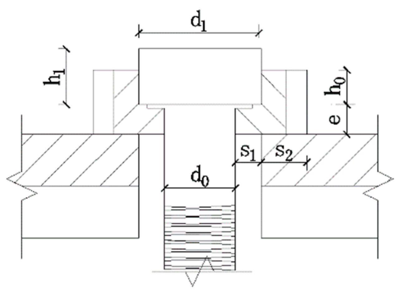
The experimental results have shown that the thickness of the washer significantly affects the anchoring performance of the FTW-OSB. To further expand the scope of parameter research and conduct a comprehensive analysis of the influencing factors on the anchoring performance of the FTW-OSB, the above parameters are shown in Figure 10.
The parameter analysis plan is shown in Table 4. M16, M20, and M24 FTW-OSBs with the washers of e = 0.2 d0, h0 = 0.25 h1, μ = 0.4, γ = 0, s1 = 5 mm, and s2 = 0.8 s1 (where d0 and h1 are the nominal diameter and head height of the bolt, respectively) are selected as the reference specimens. Therefore, a single sensitivity analysis is performed to reveal the influence of each parameter on the performance of FTW-OSB.

5.2. Thickness Effect of Flat Washer

The FTW-OSB load–displacement curves for M16, M20, and M24 with the flat washer are plotted in Figure 11, where the effect of the washer thickness on the anchoring performance of the FTW-OSB can be observed. The initial stiffness and ultimate tensile capacity of the FTW-OSB increased significantly with the thickness of the flat washer. For instance, as the washer thickness increased from 0.1 d0 to 0.2 d0 and 0.3 d0, the initial stiffness of the M24 bolt increased by 14.8% and 26.8%, and the tensile ultimate capacity increased by 36.5% and 63.4%, respectively. Moreover, when the washer thickness reached e = 0.3 d0, the initial stiffness and tensile strength of all types of FTW-OSB reached the same level as that of the same size ordinary 10.9 high-strength bolts. Therefore, it is recommended to use a washer thickness of 0.3 d0. As the bolt diameter increases, the influence of the flat washer thickness on the anchoring performance of FTW-OSB gradually increases because the effect of insufficient compaction of the washer against the plate diminishes with the increasing thickness of the washer.

5.3. The Influence of Thickness for L-Shaped Washer

The L-shaped washer was selected, and the side wall height of the washer was uniformly set to 0.25 h1. The FTW-OSB load–displacement curves for M16, M20, and M24 are shown in Figure 12. As can be seen from the figure, with the increase in the thickness of the L-shaped washer, the initial stiffness and ultimate tensile capacity of the FTW-OSB are improved. When the thickness of the L-shaped washer is e = 0.2 d0 and e = 0.3 d0, the load–displacement curves of each type of the FTW-OSB and the corresponding high-strength bolts basically coincide, indicating that the anchoring performance of the FTW-OSB has reached the same level as the corresponding high-strength bolt. Therefore, it is recommended that the thickness of the L-shaped washer for FTW-OSB be 0.2 d0.

5.4. The Influence of the Side Wall Height

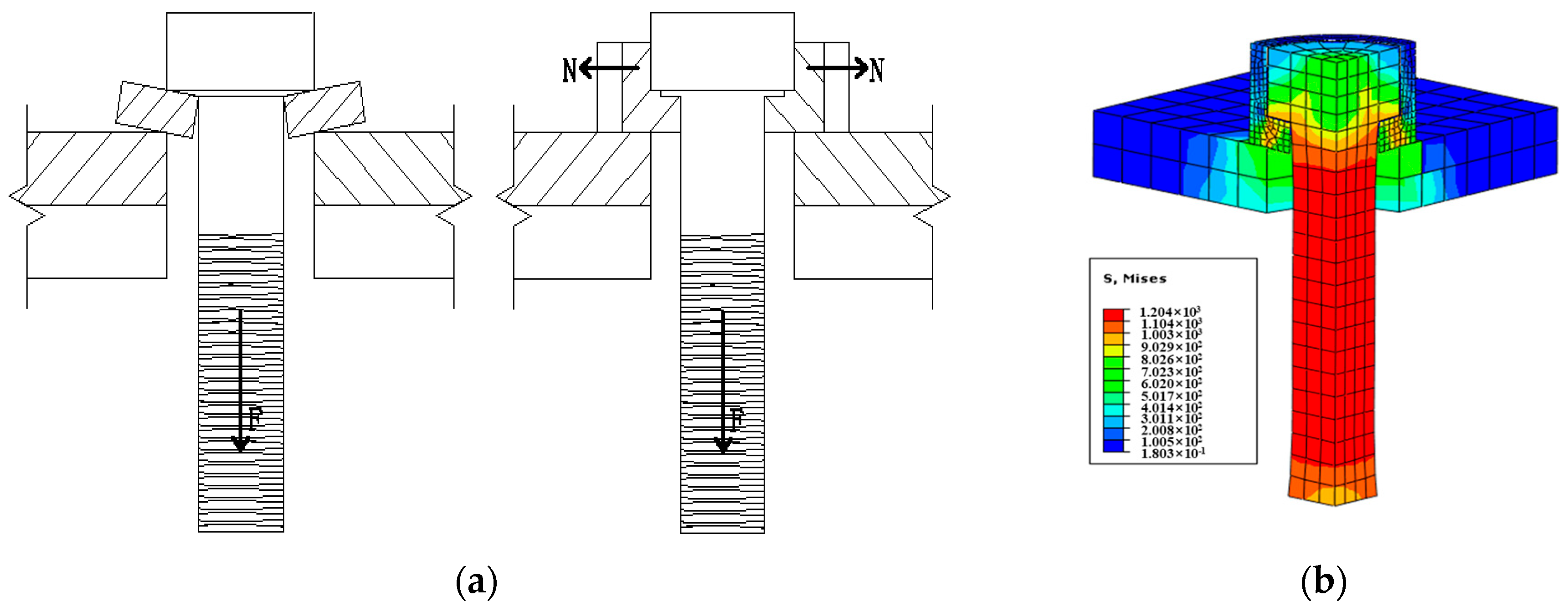
As shown in Figure 13a, to solve the problem of the flat washer of the FTW-OSB curling up at the outer edge under tension, it was proposed to change the washer shape from a cross to an L-shape to suppress flipping. From the stress distribution diagram of the FTW-OSB under tension in Figure 13b, it was found that the stress at the top of the L-shaped washer’s side wall was small, and only the base of the side wall bore some pressure.
Figure 14 shows the load–displacement curves of FTW-OSBs with M16, M20, and M24 bolts when the side wall height of the L-shaped washer changes. With the increase in the side wall height of the washer, the initial stiffness and ultimate tensile capacity of the FTW-OSB are greatly improved. For example, the initial stiffness of the M20 bolt increased by 13.9% and 18.3%, and the tensile capacity increased by 23.8% and 24.5%, respectively. On the other hand, the load–displacement curves of the FTW-OSB with washer side wall heights of h0 = 0.25 h1 and h0 = 0.5 h1 almost coincide, indicating that the side wall height h0 of the washer greater than 0.25 h1 has little effect on the anchoring performance of the new bolt. Therefore, it is recommended to design the side wall height of the L-shaped washer as 0.25 h1.

5.5. The Influence of Friction Coefficient

The load–displacement curves of the M16, M20, and M24 FTW-OSBs with the thickness of the washer at 0.2 d0 are shown in Figure 15 as the height of the washer’s side wall changes. As shown in the figure, the load–displacement curves of the FTW-OSB of various models basically coincide with those of the corresponding ordinary 10.9-grade high-strength bolts with the increase in the friction coefficient, which indicates that the friction coefficient has little effect on the anchorage performance of FTWO-OSBDE. Therefore, this paper adopts the friction coefficient between the upper and lower contact surfaces of the L-shaped washer as μ = 0.4 according to the Code for Design of Steel Structures [28] and no further optimization is performed.

5.6. The Influence of Upper Contact Surface Size on Washer

The diameter of the FTW-OSB bolt head determines the size of the bolt hole and also the upper contact surface size s1 on the washer. Figure 16 shows the load–displacement curve of the FTW-OSB anchor when the contact surface size on the washer changes. As shown in Figure 14, when s1 is 3 mm, 4 mm, and 5 mm, the ultimate tensile loads of the M16, M20, and M24 FTW-OSBs reach the maximum value. As the contact surface area continues to increase, the load–displacement curves of the bolts basically coincide. For example, for the M20 FTW-OSB, compared with s1 = 4 mm, the initial stiffness of the bolt decreases by 17.1% and 5.6% when s1 = 2 mm and s1 = 3 mm, respectively, and the ultimate capacity decreases by 26.7% and 9.7%, respectively. Therefore, it is recommended that the contact surface size on the washer of the M16, M20, and M24 FTW-OSBs should be s1 = 0.2 d0, and the bolt head diameters should be d1 = 22 mm, d1 = 28 mm, and d1 = 34 mm, respectively.

5.7. The Influence of under Contact Surface Size on Washer

Figure 17 shows the FTW-OSB anchorage performance load–displacement curve when the under contact surface size of the washer changes. As shown in Figure 17, when s2 = 0.6 s1, 0.8 s1, and 1.0 s1, the single-side bolts M16, M20, and M24 achieve the maximum tensile ultimate capacity. As the under contact surface size of the washer continues to increase, the load–displacement curves of the bolts overlap. For example, compared with s2 = 0.8 s1, when s2 = 0.4 s1 and s2 = 0.6 s1, the initial stiffness of the M20 bolt decreases by 2.9% and 1.5%, and the ultimate capacity decreases by 8.4% and 4.6%, respectively.

6. Conclusions

A new type of bolt, the flip-top washer one-side bolt (FTW-OSB), has been developed that has a similar load-bearing capacity to ordinary high-strength bolts but is more convenient to install, based on the existing Gr10.9 high-strength bolt. The anchoring performance of the FTW-OSB was studied using a combination of tests and finite element simulations, with analysis focused on the failure mode, load–displacement curve, and ultimate capacity. The influencing factors that affect the anchoring performance of the FTW-OSB were analyzed through parameter analysis, and corresponding construction suggestions were proposed. The specific conclusions are as follows:
  • The novel flip-top washer one-side bolt (FTW-OSB) has been developed using high-strength bolts as the base material. The profiled washer, aided by the torsional force of the torsion spring, rebounds in the closed section to form the anchoring end. The load-bearing performance of the L-shaped washer surpasses that of the I-shaped washer.
  • There are two types of failure modes for the FTW-OSB: one is the shear failure of the washer, and the other is the tensile failure of the bolt rod. As the thickness, side wall height, and contact surface size of the washer increase, the load-bearing capacity of the washer is enhanced, and the failure mode of the bolt changes from shear failure of the washer to tensile failure of the bolt rod. The single-side bolt fully utilizes its load-carrying capacity, and its anchoring performance reaches the same level as that of the same model of ordinary high-strength bolts.
  • The main parameters that affect the anchoring performance of the FTW-OSB are the thickness of the washer e, the height of the washer side wall h0, and the size of the contact surfaces on the upper and under of the washer, s1 and s2, respectively. When e = 0.2 d0, h0 = 0.25 h1, s1 = 0.2 d0 (h1 is the bolt head height), and s2 = 0.8 s1, the anchoring performance of the FTW-OSB is equivalent to that of the same model of the high-strength bolt.
  • The degree of influence on the anchoring performance of the FTW-OSB in descending order is washer thickness e > washer side wall height h0 > upper contact surface size of the washer s1 > under contact surface size of the washer s2 > friction coefficient μ of the contact surface.
Currently, the research focus is on the anchoring performance of individual FTW-OSBs, while ignoring the stiffness of the plate. On the other hand, the group anchoring behavior of new bolts should also be noted. Both of these need to be considered in future research.

Author Contributions

Conceptualization, L.L., D.M. and H.C.; methodology, D.M. and Q.Y.; formal analysis, Y.L.; investigation, Z.L.; resources, D.M. and H.C.; software, Q.Y. and Z.L.; data curation, H.C. and Z.L.; supervision, H.C.; writing—original draft preparation, H.C. and Z.L.; writing—review and editing, L.L., D.M., H.C. and Z.L. All authors contributed equally to this paper. All authors have read and agreed to the published version of the manuscript.

Funding

This research was funded by the National Science Foundation of China (grant numbers 51408596) and Science and Technology Program Project of Shandong Electric Power Engineering Consulting Institute.

Data Availability Statement

Data are contained within the article.

Acknowledgments

The financial support from the National Science Foundation of China (grant numbers 51408596) and Science and Technology Program Project of Shandong Electric Power Engineering Consulting Institute is greatly appreciated.

Conflicts of Interest

The authors declare no conflict of interest.

References

  1. Le, S.L.; Qi, L.Z.; Wu, L.; Li, C.; Jian, L.Y.; Liu, M.; Zhou, L.F.; Jun, W.P. Experimental and theoretical modeling for predicting bending moment capacity of T-head square-neck one-side bolted endplate to tube column connection. J. Build. Eng. 2021, 43, 103104. [Google Scholar]
  2. Xu, T.; Wang, W.; Yi, C.Y. A review on foreign research status of one-side bolt. Steel Constr. 2015, 8, 27–33. [Google Scholar]
  3. Hoogenboom, A.J. Flow Drill for the Provision of Holes in Sheet Material. U.S. Patent No. 4,454,741, 19 June 1984. [Google Scholar]
  4. France, J.E.; Davison, J.B.; Kirby, P.A. Strength and Rotational Stiffness of Simple Connections to Tubular Columns Using Flowdrill Connectors. J. Constr. Steel Res. 1999, 50, 15–34. [Google Scholar] [CrossRef]
  5. Lee, J.; Goldsworthy, H.M.; Gad, E.F. Blind Bolted T-Stub Connections to Unfilled Hollow Section Columns in Low Rise Structures. J. Constr. Steel Res. 2010, 66, 981–992. [Google Scholar] [CrossRef]
  6. Ajax Engineered Fasteners. One Sided Structured Fastening System. Available online: https://www.westcoastfasteners.com.au/pdf/ajax%20handbook.pdf (accessed on 1 January 2019.).
  7. Mourad, S. Behaviour of Blind Bolted Moment Connections for Square HSS Columns. Ph.D. Thesis, McMaster University, Hamilton, ON, Canada, 1993. [Google Scholar]
  8. Mourad, S.; Korol, R.M.; Ghobarah, A. Design of Extended End-Plate Connections for Hollow Section Columns. Can. J. Civ. Eng. 1996, 23, 277–286. [Google Scholar] [CrossRef]
  9. Lindapter International. Type HB (Hollo-Bolt) Catalogue Pages. Available online: https://www.lindapterdistributor.com.au/wp-content/uploads/2020/11/Hollo-Bolt-Technical-DataUpdated.pdf (accessed on 3 March 2017).
  10. Blind Bolt Compay. Blind Bolt Installation and Removal Instructions. Available online: https://www.blindbolt.co.uk/wp-content/uploads/2022/07/BB_fitting_instructions_2020.pdf (accessed on 5 May 2018).
  11. Wang, W.; Li, M.; Chen, Y.; Jian, X. Cyclic behavior of endplate connections to tubular columns with novel slip-critical blind bolts. Eng. Struct. 2017, 148, 949–962. [Google Scholar] [CrossRef]
  12. Wang, Z.Y.; Wang, Q.Y. Yield and ultimate strengths determination of a blind bolted endplate connection to square hollow section column. Eng. Struct. 2016, 111, 345–369. [Google Scholar] [CrossRef]
  13. Pokharel, T.; Goldsworthy, H.M.; Gad, E.F. Tensile behaviour of double headed anchored blind bolt in concrete filled square hollow section under cyclic loading. Constr. Build. Mater. 2019, 200, 146–158. [Google Scholar] [CrossRef]
  14. Yeomans, N.F. Rectangular Hollow Section Column Using Lindapter Hollobolt; Tubular Structures VIII, Choo and van der Vegte Balkema: Rotterdam, The Netherlands, 1998. [Google Scholar]
  15. Elghazouli, A.Y.; Málaga-Chuquitaype, C.; Castro, J.M. Experimental monotonic and cyclic behaviour of blind bolted angle connections. Eng. Struct. 2009, 31, 2540–2553. [Google Scholar] [CrossRef]
  16. Nakajima, K.; Suzuki, H.; Kawabe, Y. Experimental study on High strength One-sided bolted joints. In Proceedings of the Sixth International IABMAS Conference, Stresa, Italy, 8–12 July 2012. [Google Scholar]
  17. Agheshlui, H. Anchored Blind Bolted Connections within SHS Concrete Filled Columns. Aust. Earthq. Eng. Soc. 2011, 62, 378–390. [Google Scholar]
  18. Agheshlui, H.; Goldsworthy, H.; Gad, E.; Fernando, S. Tensile behaviour of anchored blind bolts in concrete filled square hollow sections. Mater. Struct. 2016, 49, 1511–1525. [Google Scholar] [CrossRef]
  19. Agheshlui, H.; Goldsworthy, H.; Gad, E. Tensile Behavior of Groups of Anchored Blind Bolts within Concrete-Filled Steel Square Hollow Sections. J. Struct. Eng. 2016, 142, 515–525. [Google Scholar] [CrossRef]
  20. Oktavianus, Y.; Chang, H.F.; Goldsworthy, H.; Gad, E. Component model for pull out beha- viour of headed anchored blind bolt within concrete filled circular hollow section. Eng. Struct. 2017, 148, 210–224. [Google Scholar] [CrossRef]
  21. Xu, W. Study on the Anchoring Performance of Novel One-Sided Bolt with Flip-Top Washer. Master’s Thesis, China University of Mining and Technology, Xuzhou, China, 2019. [Google Scholar]
  22. Yue, Z.; Mei, L.; Jie, M.Q.; Hua, L.Z.; Jun, W.P.; Le, S.L. Yield line patterns of T-stubs connected by thread-fixed one-side bolts under tension. J. Constr. Steel. Res. 2020, 6, 105932. [Google Scholar]
  23. Gohari, S.; Sharifi, S.; Sharifishourabi, G.; Vrcelj, Z.; Abadi, R. Effect of temperature on crack initiation in gas formed structures. J. Mech. Sci. Technol. 2013, 27, 2745–3754. [Google Scholar] [CrossRef]
  24. Quesada, A.; Gauchia, A.; Álvarez-Caldas, C.; Román, J.L.S. Material Characterization for FEM Simulation of Sheet Metal Stamping Processes. Adv. Mech. Eng. 2014, 6, 167147. [Google Scholar] [CrossRef] [Green Version]
  25. JGJ 82—2011; Technical Specification for High Strength Bolt Connections of Steel Structures. China Architecture & Building Press: Beijing, China, 2011. (In Chinese)
  26. ASTM A370-18; Standard Test Methods and Definitions for Mechanical Testing of Steel Products. American Society for Testing and Materials ASTM: Philadelphia, WC, USA, 2018.
  27. JGJ/T 101-2015; Specification for Seismic Test of Buildings. China Architecture & Building Press: Beijing, China, 2015. (In Chinese)
  28. GB 50017-2003; Code for Design of Steel Structures. China Planning Press: Beijing, China, 2003. (In Chinese)
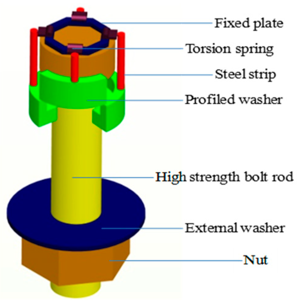
Figure 1. The conception design of FTW-OSB.
Buildings 13 01571 g001
Figure 2. The installation process of FTW-OSB.
Buildings 13 01571 g002
Figure 3. Force analysis of profiled washer.
Buildings 13 01571 g003
Figure 4. Test setup of FTW-OSB: (a) specimen installation; (b) displacement meter arrangement.
Buildings 13 01571 g004
Figure 5. Failure modes of FTW-OSB: (a) F16-1 (b); F16-2; (c) F16-3; (d) F20-1; (e) F20-2; (f) F20-3 (g); F24-1; (h) F24-2; (i) F24-3.
Buildings 13 01571 g005aBuildings 13 01571 g005b
Figure 6. Load–displacement curve of test bolts: (a) M16; (b) M20; (c) M24.
Buildings 13 01571 g006
Figure 7. (a) Comparison of mesh density; (b) finite element model of FTW-OSB; (c) type of mesh.
Buildings 13 01571 g007
Figure 8. Material model.
Buildings 13 01571 g008
Figure 9. Comparison between FEM and test results: (a) failure modes; (b) load–displacement curves.
Buildings 13 01571 g009
Figure 10. Parameters for FTW-OSB. e: the thickness of the profiled washer; h0: the side wall height of the profiled washer; μ: the friction coefficient of the upper and lower contact surface for the washer; s1: the contact width on the upper surface of the washer; s2: the contact width on the lower surface of the washer.
Buildings 13 01571 g010
Figure 11. Influence of the flat washer thickness on FTW-OSB anchoring performance: (a) M16; (b) M20; (c) M24.
Buildings 13 01571 g011
Figure 12. Influence of the L-shape profiled washer thickness on FTW-OSB anchoring performance under same height: (a) M16; (b) M20; (c) M24.
Buildings 13 01571 g012
Figure 13. L-shaped profiled washer schematic: (a) force schematic; (b) stress distribution.
Buildings 13 01571 g013
Figure 14. Influence of the profiled washer height on FTW-OSB anchoring performance: (a) M16; (b) M20; (c) M24.
Buildings 13 01571 g014
Figure 15. Influence of the profiled washer with thickness e = 0.2 d0 friction coefficient on FTW-OSBs’ anchoring performance: (a) M16; (b) M20; (c) M24.
Buildings 13 01571 g015
Figure 16. Influence of the profiled washer upper surface size on FTW-OSB anchoring performance: (a) M16; (b) M20; (c) M24.
Buildings 13 01571 g016
Figure 17. Influence of the profiled washer under surface size on FTW-OSB anchoring performance: (a) M16; (b) M20; (c) M24.
Buildings 13 01571 g017
Table 1. Test piece parameter table.
No.Diameter
of Bolt/mm
Thickness
of Profiled Washer/mm
Height
of Profiled Washer/mm
M16F16-1161.614.8
F16-2163.214.8
F16-3164.814.8
M20F20-1202.016.0
F20-2204.016.0
F20-3206.016.0
M24F24-1242.417.2
F24-2244.817.2
F24-3247.217.2
Table 2. Mechanical properties.
SectionThickness/mmfy 1/MPafu 2/MPafu/fy 3δ 4/%E5/105 Mpa
rectangle10420.5539.11.2824.32.03
rectangle20424.3545.11.2823.12.06
round12710.2864.51.2225.31.95
1 means yield strength, 2 means tensile strength, 3 means strength yield ratio, 4 means elongation, 5 means elasticity modulus.
Table 3. Summary of FTW-OSB anchoring performance test results.
LabelInitial Stiffness N/m × 105Field Load/kNTheoretical Yield Load/kNUltimate Capacity/kNTheoretical Ultimate Capacity/kN
F16-1273.2392.05111.50115.06135.73
F16-2321.3795.58111.50122.10135.73
F16-3329.6595.67111.50124.95135.73
F20-1238.6571.71174.0091.85211.80
F20-2448.57169.62174.00214.95211.80
F20-3478.17173.06174.00217.23211.80
F24-1275.6887.82250.70118.37305.17
F24-2446.18170.15250.70213.36305.17
F24-3443.10216.02250.70289.95305.17
Table 4. Parameters considered for FTW-OSB.
ParametersNotationBenchmarkExpansion
Washer thicknesse0.2 d00.1 d0, 0.3 d0
Side wall heighth00.25 h10.1 h1, 0. 5 h1
Friction coefficientμ0.40.35, 0.5
Upper contact surface sizes10.2 d00.1 d0, 0.3 d0
Under contact surface sizes20.8 s10.6 s1, 1.0 s1
Note: d0 = 20 mm is the nominate diameter of the bolt shank, h1 = 14 mm is the height of the bolt head.
Disclaimer/Publisher’s Note: The statements, opinions and data contained in all publications are solely those of the individual author(s) and contributor(s) and not of MDPI and/or the editor(s). MDPI and/or the editor(s) disclaim responsibility for any injury to people or property resulting from any ideas, methods, instructions or products referred to in the content.