Article

Relationship between the Intermediate Soil State and Settlement Control Measures during Tunnel Construction Undercrossing the Existing Station

1
Key Laboratory of Building Structural Retrofitting and Underground Space Engineering, School of Civil Engineering, Shandong Jianzhu University, Jinan 250101, China
2
China Railway Fourteenth Bureau Group Co., Ltd., Jinan 266000, China
*
Author to whom correspondence should be addressed.
Buildings 2023, 13(8), 1933; https://doi.org/10.3390/buildings13081933
Submission received: 6 June 2023 / Revised: 2 July 2023 / Accepted: 25 July 2023 / Published: 29 July 2023
(This article belongs to the Section Construction Management, and Computers & Digitization)

Abstract

:
Settlement control of existing stations has consistently been a key issue in tunnel construction. Intermediate soil has a significant influence on the settlement of the existing station as a connector between the new tunnel and the existing station which should be considered when selecting settlement control measures. To clarify the relationship between the state of the intermediate soil and the settlement and control measures of the existing station, this study investigated 49 new tunnel projects under existing stations and elucidated the relationship between the settlement and the settlement control measures of the existing station and the intermediate soil. The relationship between the failure of the intermediate soil and the settlement of the existing station was further analyzed by numerical simulation. Lastly, a simple mechanical model of intermediate soil failure was constructed to determine the stress state of the intermediate soil in constructing a tunnel under the existing station to guide the formulation of settlement control measures for the existing station. Hence, when the intermediate soil is completely destroyed, active control measures, such as jack or grouting lifting, should be implemented; when the intermediate soil is partially damaged, passive control measures should be undertaken. Thus, this study can provide a reference for settlement control of tunnels under existing stations.

1. Introduction

With the gradual improvement of the subway system, the number of underpass construction cases has increased [1,2,3,4]. In a new tunnel undercrossing an existing station, the existing station has a large span and complex structure and is prone to settlement, severely affecting its operational safety. Although the settlement control of existing stations is key to underpass construction [5,6,7,8,9,10,11,12], engineering safety problems are likely to occur during its construction [13,14]. Excessive settlement will lead to the local collapse of existing stations [15,16], thereby affecting regular operation and use, while surface ancillary structures will cause settlement collapse damage. In short-distance underpass construction, excavation soil disturbance has an evident influence on the settlement of the existing station. Owing to its limited bearing capacity, the soil cannot support the existing load, thus increasing the settlement of the existing station [17,18,19,20,21,22,23,24,25,26].
Therefore, many scholars have studied settlement control laws and control measures for tunnels under existing stations. Li [27] reported that the jack support method could effectively control the settlement of an overlying tunnel during the construction of an existing tunnel. Wu [28] proposed that the combined pre-support technology of a pipe roof and grouting reinforcement can effectively consolidate the in situ stress and improve the bearing capacity of the soft rock surrounding the rock, which plays a significant role in controlling settlement. Kummerer [29] reported compensation grouting to be an active method that can be divided into two stages: adjusting the intermediate soil and actual grouting, which can offset the settlement caused by tunnel excavation. Focusing on the project of Shenyang Metro Line 9 Olympic East-Olympic Center interval underpassing the existing Olympic Center Station of Line 2, Huo [30] verified the superiority of the CRD method in underpass construction via numerical simulation and simultaneously suggested deep-hole grouting reinforcement and jack-up technologies for the effective control of the settlement of existing structural floors. Through case analysis, field monitoring, and other methods, Zhang [31] clarified the response of an overlying subway station to the characteristics of double tunnels and land subsidence, as well as the importance of jacks in the application of tight underpass engineering. Li [32] compared the freezing method with three other reinforcement methods and reported that the freezing method is better at controlling surface displacement and vault settlement, while the grouting, pipe-shed, and pipe-curtain methods are favorable in controlling surface uplift.
As a connector between the new tunnel and the existing station, the intermediate soil significantly affects the settlement of the existing station. Zheng [33] reported that, when Qingdao underpasses the station, the intermediate soil is slightly weathered granite with a thickness of 4.45 m. The soil parameters were satisfactory, and the existing structural settlement was within a safe range. Zhao [34] found that the gravity load of intermediate soil is partially borne by its self-stability, whereas the remainder is borne by the lower pre-support. The lower structure is deformed under the load of the intermediate soil layer. The deformation of the intermediate soil caused settlement deformation of the upper existing structure, which became smaller with an increase in the intermediate soil foundation coefficient. Fu [35] explored the minimum safe construction distance for a new tunnel in an existing structure under different surrounding rock conditions, i.e., the minimum intermediate soil thickness. Hage Chehade [36] analyzed the position of double holes via numerical simulation and found that the soil settlement mode depended on the distance between the tunnels. Shahin [37] analyzed the earth pressure distribution and ground motion around a tunnel during tunnel excavation using finite element analysis, which depended on the distance and position between the two tunnels.
Many researchers have realized that the state of intermediate soil significantly affects the settlement of existing stations; therefore, the state of intermediate soil should be considered when selecting settlement control measures for existing stations. At present, no research has established the relationship between the state of the intermediate soil and the existing settlement control measures, which leads to the choice of settlement control measures to be discussed. To clarify this relationship, the present study first investigated 49 new tunnel projects under existing stations and elucidated the relationship between the settlement and the settlement control measures of the existing station and the intermediate soil. The relationship between the failure of the intermediate soil and the settlement of the existing station was further analyzed via numerical simulation. Lastly, a simple mechanical model of intermediate soil failure was constructed to examine the stress state of the intermediate soil in constructing the tunnel under the existing station to guide the formulation of settlement control measures for the existing station.

2. Case Investigation of Underground Tunnels Crossing Existing Stations

2.1. Case Analysis

For the analysis, 49 new tunnels beneath existing stations were investigated. Appendix A presents the tunnel construction methods, buried depth of existing stations, geological features, intermediate soil thickness, and existing settlement. The settlement control measures of the existing station in the underpass construction of the new tunnel are divided into two categories. First, if the bearing capacity of the intermediate soil is insufficient, an external force must be applied to the existing structure to restore its original deformation position and compensate for the settlement deformation; compensatory jacking measures to compensate for the settlement of existing structures include jacking of jacks and grouts. Second, the limited bearing capacity of the intermediate soil must be improved through passive reinforcement measures to support the upper load. Passive reinforcement measures include freezing methods, pipe sheds (curtains), and grouting reinforcements. Figure 1 shows the distribution of settlement control measures for the existing stations.
As shown in Figure 1, compared to the excavation span of the new tunnel, the thickness of the intermediate soil is more closely related to the settlement control measures of the existing station; the buried depth of the existing stations only had a slight effect. Thus, the correlation between the influencing factors and settlement control measures of the existing station was in the order of intermediate soil thickness > excavation span > station buried depth.
When the thickness of the intermediate soil is considerably low, tunnel excavation can easily lead to its destruction and is, thus, unable to support the existing structure effectively. Therefore, adopting compensatory jacking or relatively strong stratum reinforcement methods, such as freezing, is essential. When the thickness of the intermediate soil is less than 2 m, the jack lifting, grouting lifting, and freezing methods account for 40.42%, 12.76%, and 6.38%, respectively. When the thickness of the intermediate soil is more than 2 m, the reinforcement measures are primarily passive support measures, such as pipe roof (curtain) support and grouting reinforcement, and the proportion of compensation jacking control measures is 0. The excavation span of the tunnel also affects the selection of settlement control measures for existing stations. When the excavation span of the tunnel is large, the intermediate soil is relatively thin and long, which makes its destruction easy. Hence, strong reinforcement measures such as compensatory jacking are required. When the tunnel excavation span is greater than 20 m, the jack and grouting lifting measures account for 28.95% and 5.26%, respectively.
The study also analyzed the settlement of existing stations with different reinforcement measures, as shown in Figure 2.
The settlement of existing stations is influenced by several factors, such as the buried depth of the station, reinforcement measures, thickness of the intermediate soil, excavation span, and stratum conditions. This leads to a large dispersion in the settlement of existing stations, as shown in Figure 2. When the intermediate soil is thinner, the buried depth of the existing station, excavation span, and settlement of the existing station are larger. Figure 2 does not illustrate the law as a whole, indicating that settlement control measures play a key role. For projects with thin intermediate soils and large excavation spans, active control measures are often adopted to effectively suppress the settlement of existing structures.

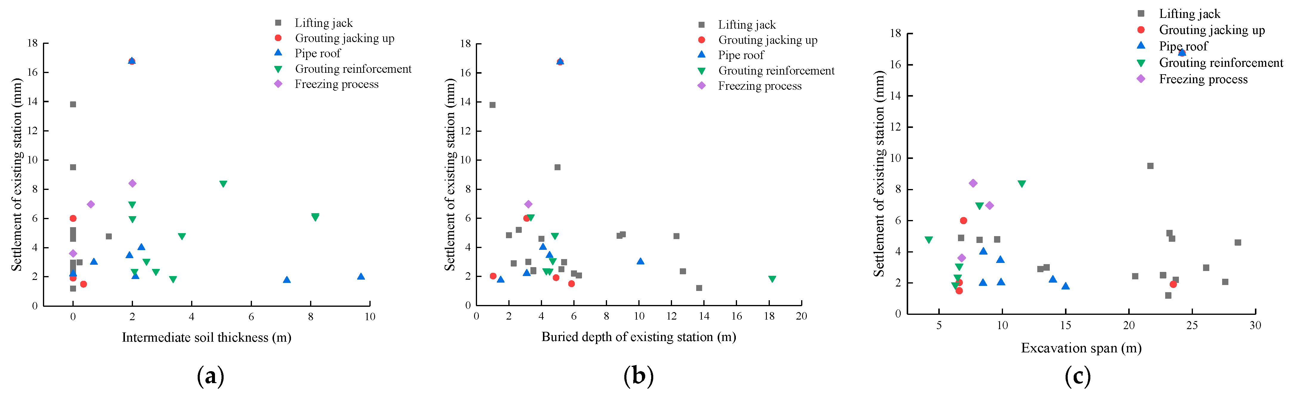
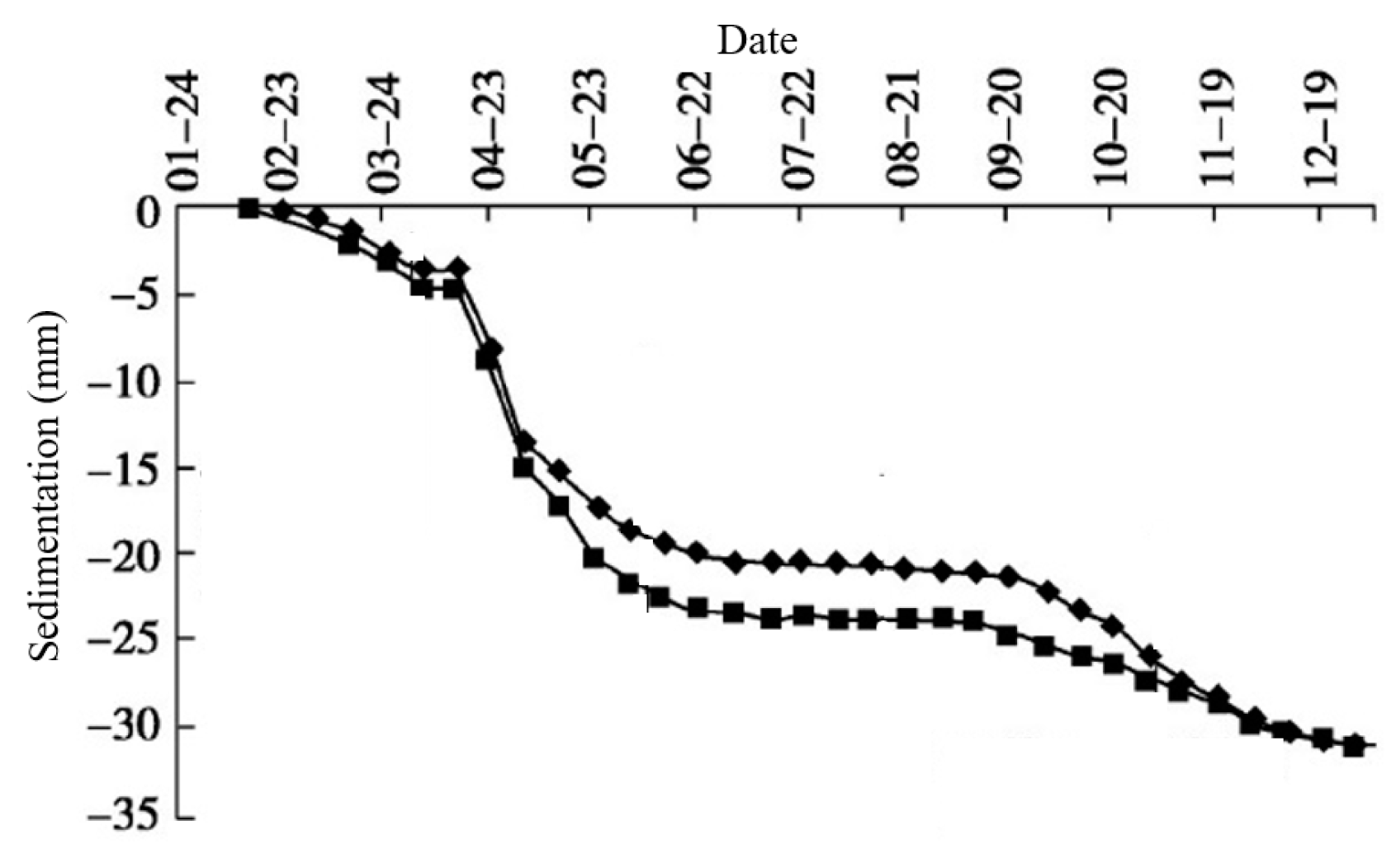
2.2. Settlement Characteristics of Existing Stations

The settlement control measures of existing stations in the underpass construction include two categories: compensation jacking and passive reinforcement. Different settlement control measures lead to different settlement laws for the existing structures.
(1)
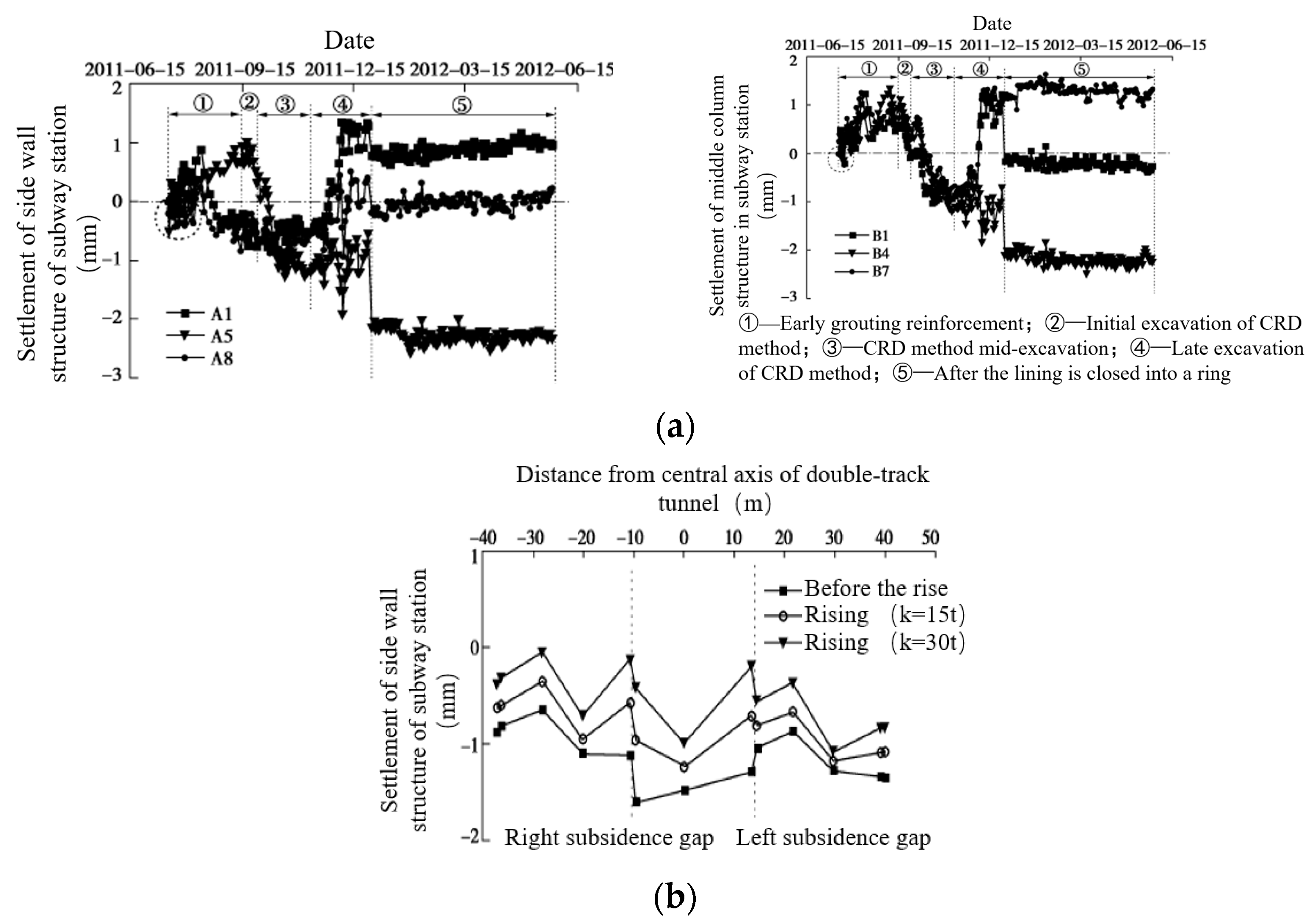
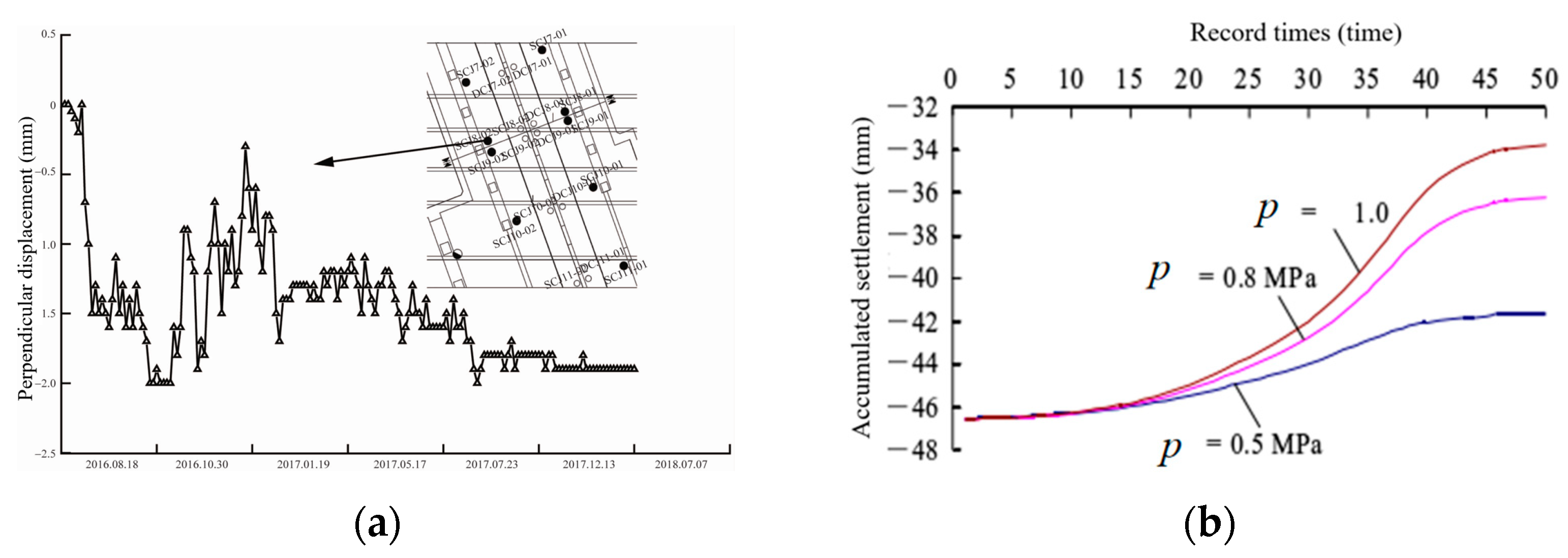
Settlement of existing stations under the action of jack and grouting jacking
The compensation jacking method primarily includes jack and grouting jacking. Both directly apply a jacking force to the existing structure through different media to ensure its settlement. Owing to the weak bearing capacity of the lower soil and insufficient support for the existing structure, the surface and existing structure have a large settlement. The settlement compensation of the existing structure is realized by actively applying jacking force, thus restoring the structural deformation and reducing large-scale settlement.
Zhang [38] provided the settlement law of an existing station in the construction of a tunnel between the Chaoyangmen and Dongdaqiao Stations of Beijing Metro Line 6 under the existing Chaoyangmen Station of Line 2 (Figure 3). A tunnel was constructed using the CRD method, and the excavation span was 22.7 m. The stratum consisted of round pebbles and silty clay. The existing station has a three-span, rectangular frame structure. Jacks were used to lift the existing station to control its settlement.
As shown in Figure 3, the existing station has a large settlement in tunnel excavation owing to excavation unloading. In the later stage of the excavation, a jack was used to lift the existing structure and control its settlement, and the deformation of the existing station was restored to its initial position. The jack-lifting force plays an important role in lifting existing stations, and the magnitude of the lifting force directly affects the settlement deformation of the existing structures. When the lifting force was high, the lifting effect of the existing station was more significant. However, when the jacking force was excessively high, it easily caused an uplift of the existing station floor and affected normal operation. Therefore, controlling the size of the jacking force is the crucial in the lifting of the existing station.
Zhang [39] provided the settlement law of the existing station in the project of the Pingguoyuan Station of Beijing Metro Line 6, underpassing the Pingguoyuan Station of the existing Metro Line 1 at zero distance (Figure 4). A tunnel was constructed using the pile–beam–arch method. The excavation span was 23.5 m, and the stratum was a sandy pebble. The existing station is a two-story, three-span box-frame structure. Grouting jacking was used to lift the existing station and control its settlement.
Similar to the jack-lifting law, grouting lifting causes an uplift in the existing structure. This ensures that the settlement deformation of the existing station is within the control standard. When the grouting pressure was higher, the lifting effect of the existing station was more evident. When the grouting pressure was excessively high, the existing structure was also uplifted.
Compensation lifting measures provide the existing structure with a compensation deformation, and the size of the compensation deformation depends on the jacking load. A reasonable jacking load setting is the key to compensating for jacking. Excessive jacking loads can cause structural damages. The jack jacking load is a concentrated load which can easily lead to an excessive load on the structure, whereas the grouting jacking load is close to a uniform load, which causes less damage to the existing structure.
(2)
Settlement of the existing station under the passive reinforcement of intermediate soil
The passive reinforcement of intermediate soil controls the existing settlement by strengthening the soil and improving its bearing capacity; this mainly includes grouting reinforcement, the freezing method, and pipe shed support. Although the freezing method has a strong reinforcement effect, it is limited to the stratum, and the number of applications is less than that of grouting reinforcement and pipe roof support.
Zhang [40] presented the settlement law for existing stations in the construction of the Chongwenmen underground excavation station of Beijing Metro Line 5 under an existing subway tunnel (Figure 5). The tunnel was constructed using the column hole method. The excavation span was 24.2 m, and the stratum was silt. A pipe roof was used to support the existing station and control its settlement.
Figure 6 shows the settlement of an existing structure with a pipe roof support. Owing to the different stiffnesses of the pipe roof and soil, the soil displacement was uneven after the construction of pipe roof, and the stress was redistributed. The soil in the excavation area converts the upper load into compressive stress, which is transferred to the feet of the arch on both sides to form a micro-soil arch. This improves the bearing capacity of the soil between the pipes. Simultaneously, the pipe roof has a certain stiffness that protects the vault from collapsing and plays an important role in carrying the upper load. The soil and pipe roof constituted a vast bearing body that shared the upper load and reduced the settlement of the existing station. Compared with compensation jacking, passive reinforcement measures of the intermediate soil fully mobilize its bearing capacity, which has a certain economy. Meanwhile, the settlement of the existing station did not exhibit a reverse deformation, and the structural damage was smaller.
Compensated jacking actively compensates for the settlement deformation of existing structures by applying a jacking force. In contrast, the passive reinforcement of intermediate soil improves its bearing capacity and reduces the settlement of existing structures. Thus, the state of the intermediate soil has a significant relationship with the settlement control of existing stations. In particular, settlement control measures should be selected according to the intermediate soil state.

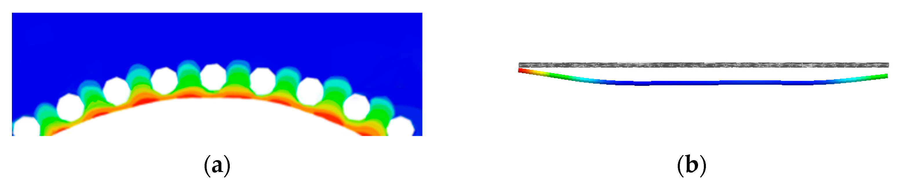
3. Influence of Intermediate Soil Damage on the Settlement of Existing Stations

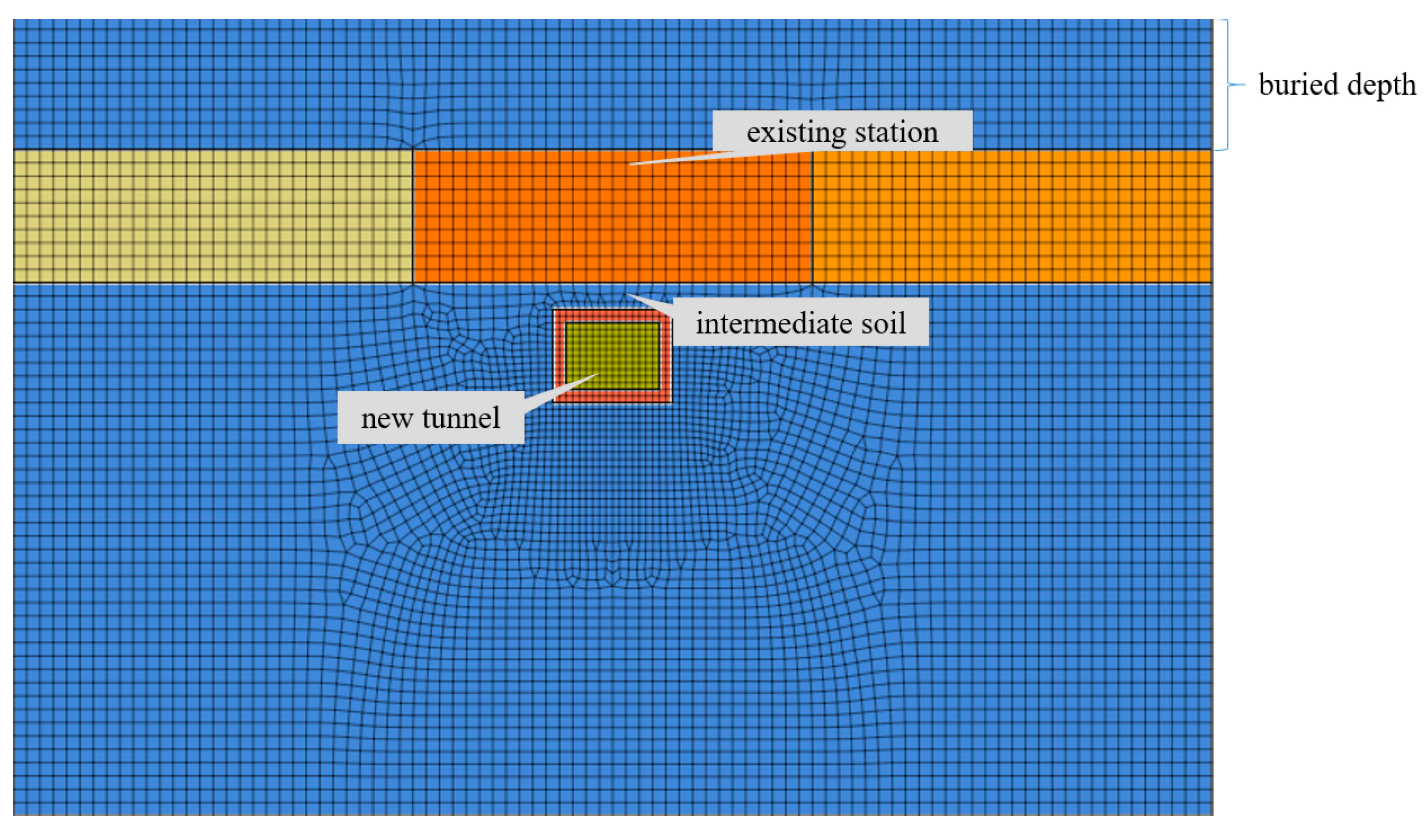
3.1. Computation Module

The stress state of the intermediate soil significantly affects the settlement of the existing structure. Therefore, a finite element model of the new tunnel beneath the existing station was established to analyze the relationship between the stress state of the intermediate soil and the settlement of the existing station. The minimum width of an ordinary subway station is 8 m, while the dimensions of the model were 90 m × 60 m. The section size of the existing station was 15 m × 10 m, the section size of the new tunnel was 9 m × 7 m, the initial support thickness was 0.35 m, the roof thickness was 1.1 m, the side wall thickness was 1.0 m, the floor thickness was 1.0 m, and the concrete strength was C30. The calculation model is illustrated in Figure 7. The formation and station parameters are detailed in Table 1 and Table 2. The numerical simulation considered the thickness of the intermediate soil, mechanical parameters, excavation span of the new tunnel, and buried depth of the existing station as single variables to analyze the failure of the intermediate soil and settlement of the existing station under different factors [42].

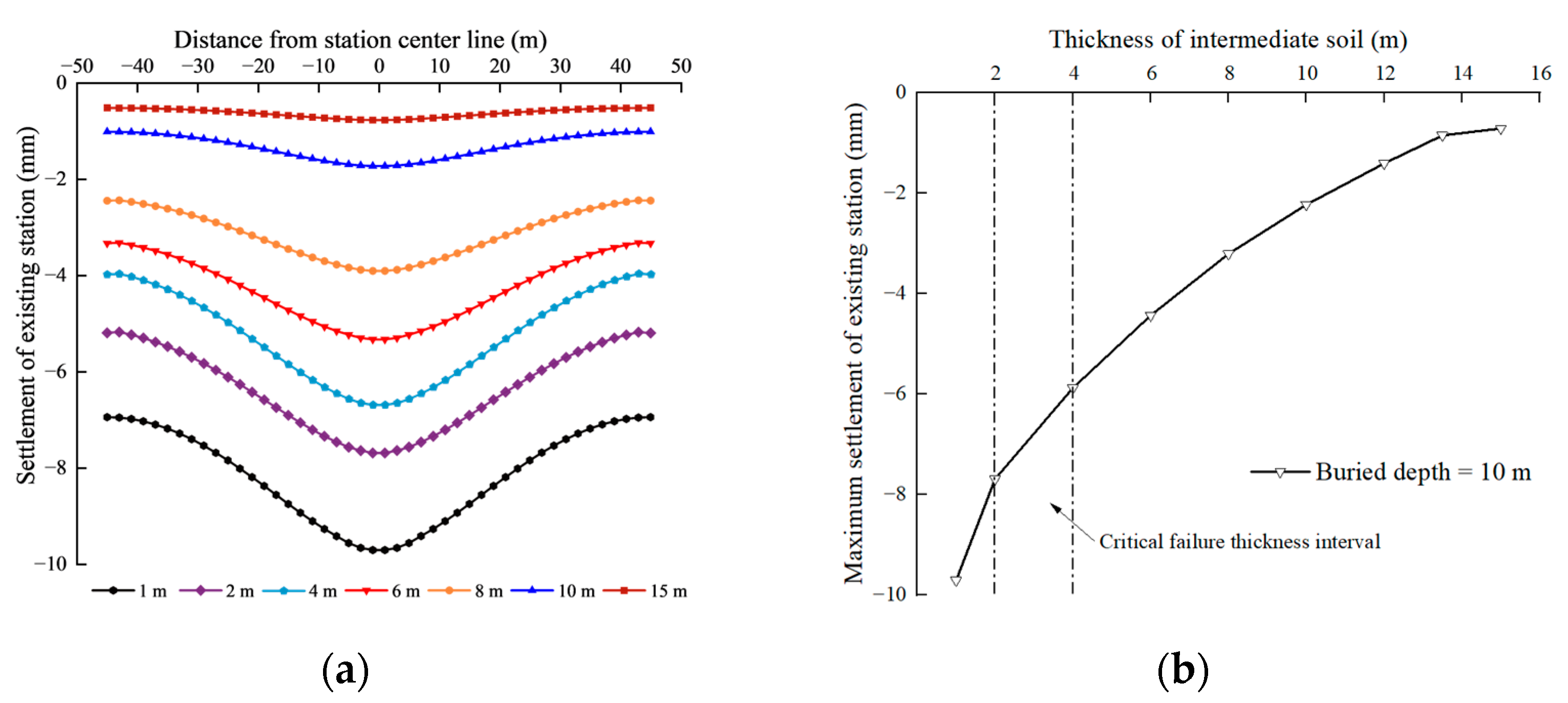
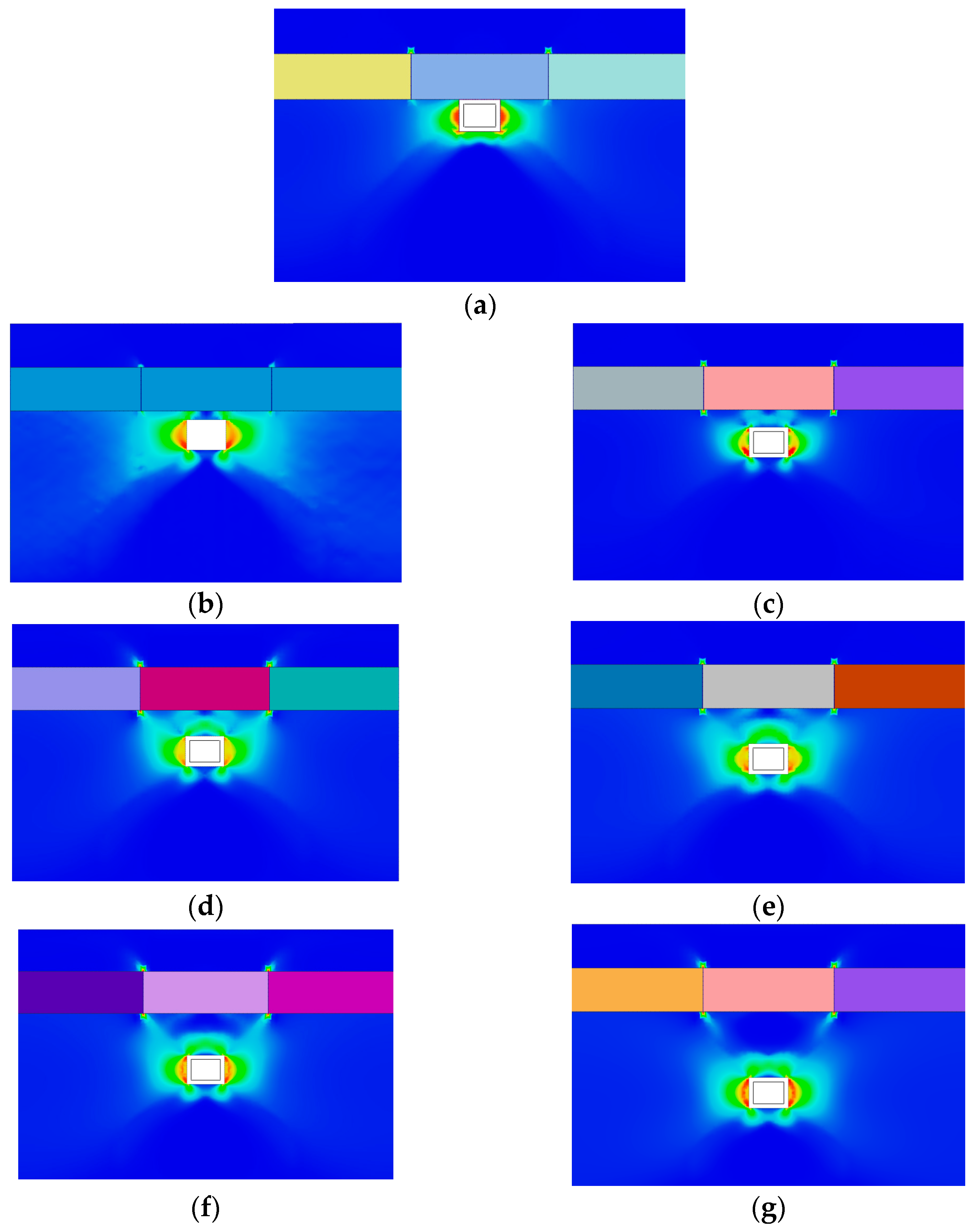
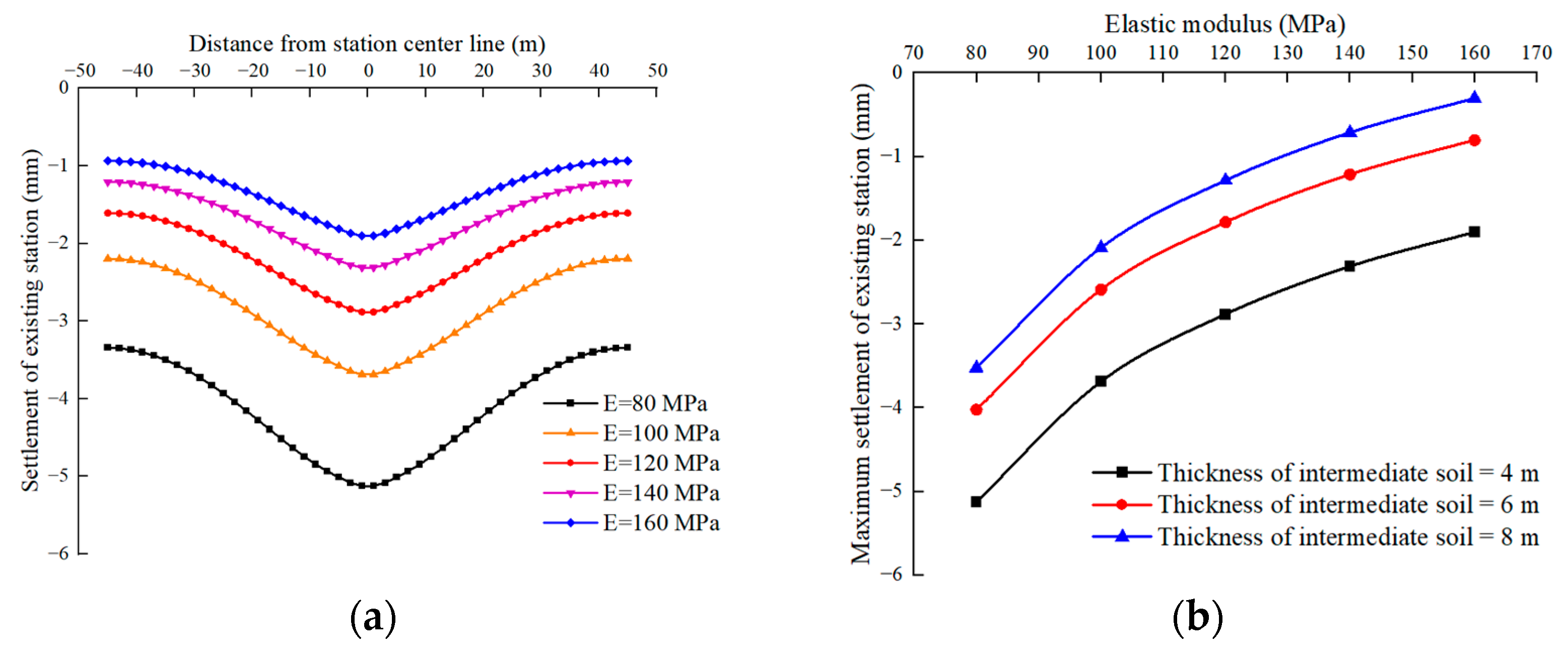
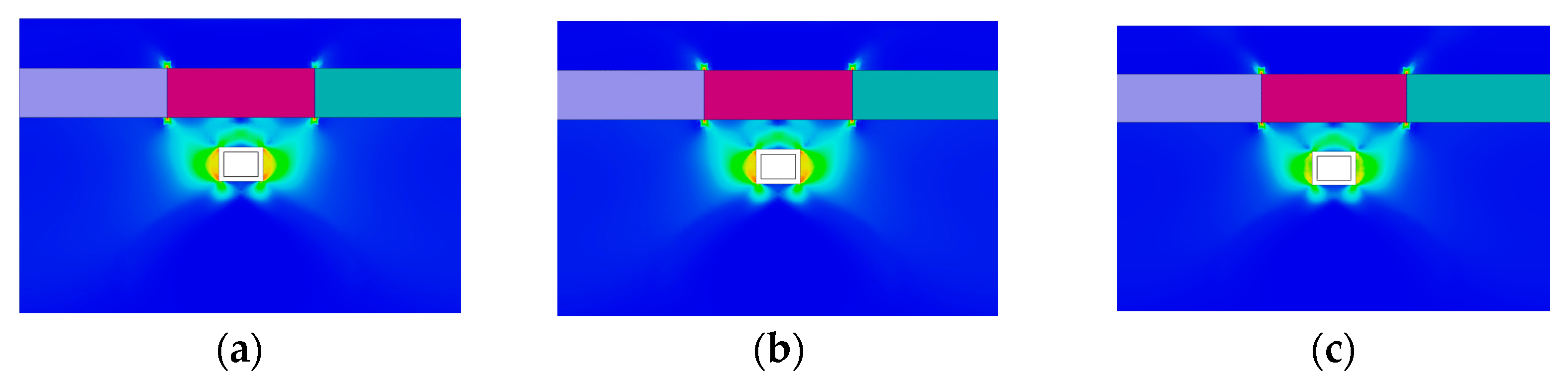
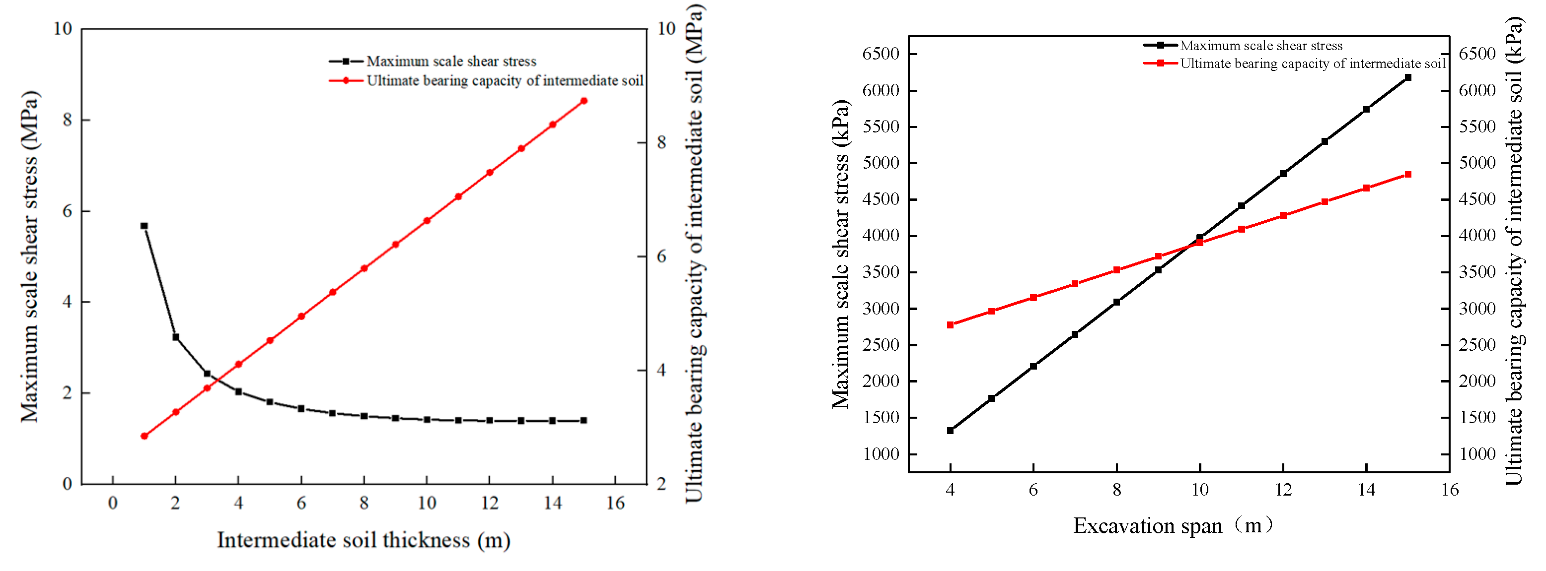
3.2. Influence of Intermediate Soil Thickness on the Settlement of Existing Stations

The excavation of the new station disturbs the intermediate soil, leading to settlement deformation of the existing structure. Therefore, models with intermediate soil thicknesses of 1, 2, 4, 6, 8, 10, and 15 m were established for finite element calculations to explore the influence of intermediate soil with different thicknesses on the settlement of existing stations. The settlement deformation diagrams of the existing structures at different intermediate soil thicknesses are shown in Figure 8.
As shown in Figure 8a, when the thickness of the intermediate soil was larger, the settlement of the existing station was smaller. When the thickness of the intermediate soil was 15 m, the maximum settlement at the existing station was 0.2 mm. When the thickness of the intermediate soil was 1 m, the maximum settlement at the existing station was 9.8 mm. In addition, when the intermediate soil was thinner, the supporting effect of the soil on the upper structure was weaker; thus, the destruction of the soil under excavation unloading became easy. As shown in Figure 8b, as the intermediate soil became thinner, the settlement of the existing station structure accelerated. This indicated that the intermediate soil was destroyed as it became thinner, and the settlement of the existing structure increased rapidly. Figure 9 shows the plastic distribution of the intermediate soil for different intermediate soil thicknesses.
As shown in Figure 9, when the thickness of the intermediate soil was less than 2 m, the plastic zone was mainly distributed on both sides of the excavation area of the new station and within the scope of the intermediate soil. At this time, the plastic zone penetrates the intermediate soil, which is completely destroyed. When the thickness of the intermediate soil was more than 2 m, the intermediate soil was destroyed above the new tunnel. However, the plastic zone did not completely penetrate the intermediate soil, which was partially destroyed. When the intermediate soil was completely destroyed, the bearing capacity was lost, and no supporting effect was present on the existing station. The settlement of existing stations was evidently increased. When the intermediate soil is not completely destroyed, it can provide support to the existing stations. The calculation shows that the critical thickness of the intermediate soil damage was approximately 2–4 m, which was also the critical point for an evident increase in the settlement of the existing station (Figure 8b).
An existing station cannot be supported when the intermediate soil is completely destroyed. Therefore, compensation jacking measures should be implemented to reduce settlement of existing stations. When the intermediate soil is not destroyed completely, using the intermediate soil for bearings is economical, which can be reinforced to improve its bearing capacity.

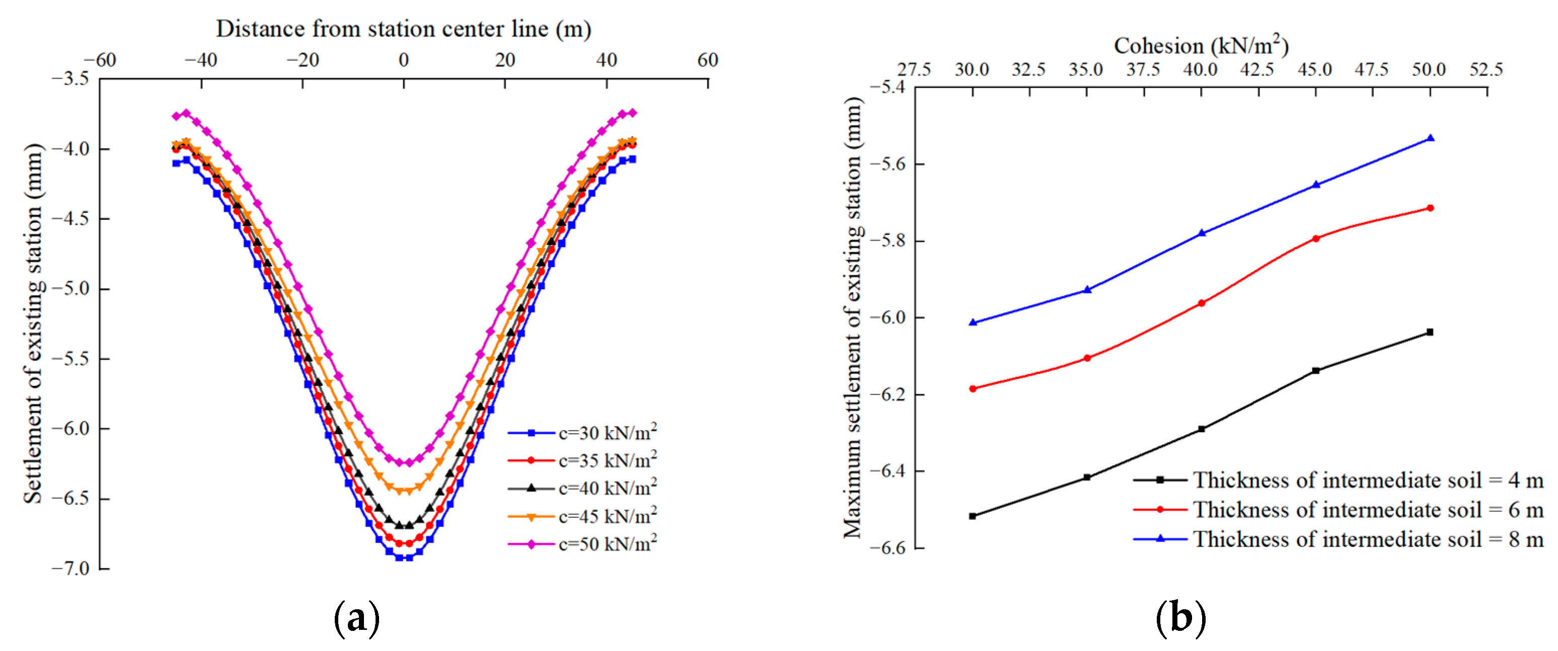
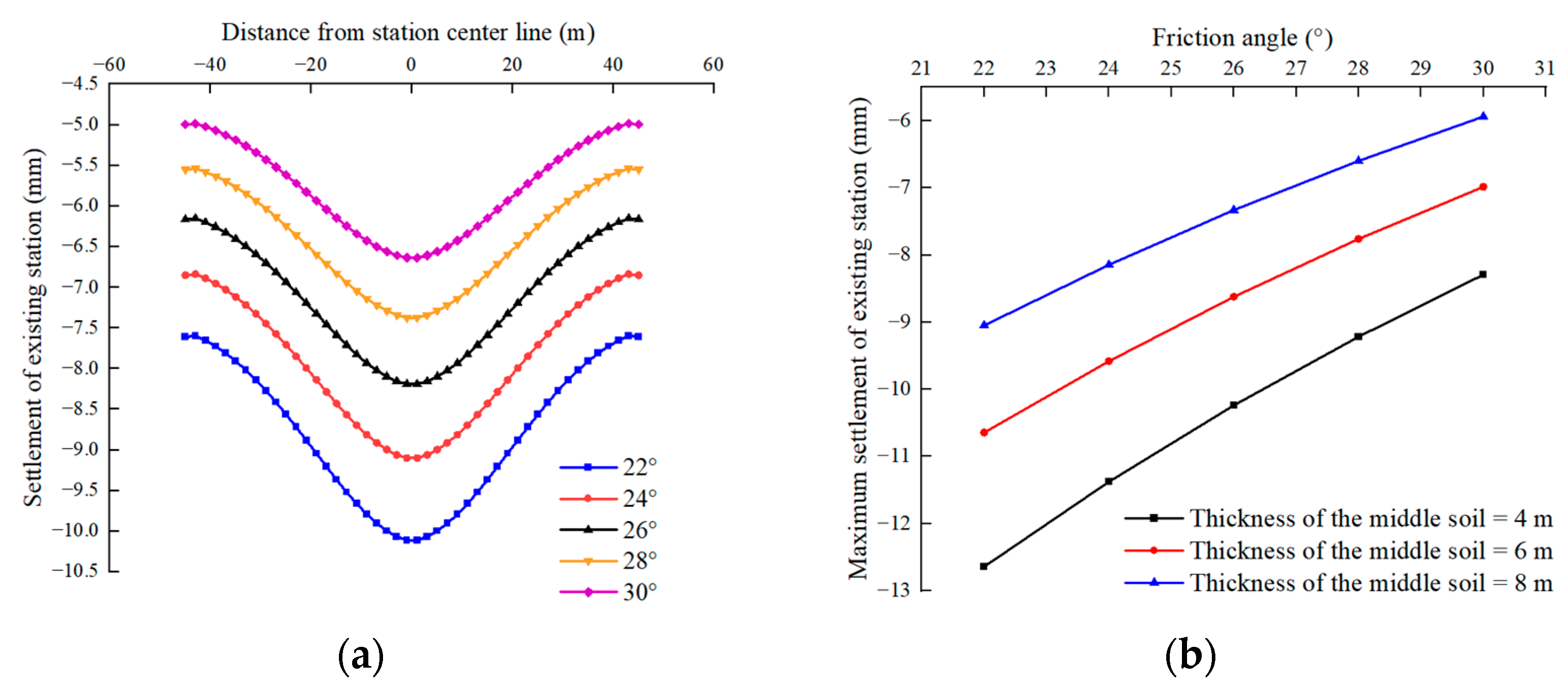
3.3. Influence of Mechanical Parameters of Intermediate Soil on the Settlement of Existing Stations

The intermediate soil can be easily destroyed when its mechanical properties are weak, which lowers its bearing capacity. Hence, the effects of the elastic modulus, internal friction angle, and cohesion of the intermediate soil are discussed.
(1)
Effect of soil elastic modulus on the settlement of existing stations
The mechanical parameters of the intermediate soil also affect the settlement of the existing stations. The elastic modulus of the soil was analyzed at 80, 100, 120, 140, and 160 MPa. The settlement deformation of the existing stations and distribution of the plastic zone of the intermediate soil affected by different elastic moduli are shown in Figure 10 and Figure 11, respectively.
As shown in Figure 10, when the elastic modulus was 80 MPa, the maximum settlement of the existing station was 5.1 mm. In contrast, when the elastic modulus was 160 MPa, the maximum settlement of the existing station was 1.8 mm. The elastic modulus of the soil has an evident influence on the settlement deformation of the existing stations. When the elastic modulus is larger, the mechanical properties of the soil are improved. Consequently, the capacity of the soil to bear the upper load is improved, and the settlement of the existing stations becomes smaller.
As shown in Figure 11, as the elastic modulus of the soil layer increased, the failure range of the plastic zone of the intermediate soil gradually decreased. Thus, a greater elastic modulus of the soil denotes a stronger stability, gradually enhancing its bearing capacity. Under the same load, the degree of soil damage was small, and the settlement deformation of the existing station was gradually reduced.
(2)
Effect of soil cohesion on the settlement at existing stations
To explore the effect of soil cohesion on the settlement of existing stations, soil cohesion of 30, 60, and 90 kN/m2 was selected for the analysis; the other parameters were kept the same. The settlement deformations of the existing stations and range of the plastic zone of the intermediate soil are shown in Figure 12 and Figure 13, respectively.
As shown in Figure 12, the effect of varying cohesion on the settlement of existing stations was not evident. When the soil cohesion was 30 kN/m2, the maximum settlement at the existing station was 6.25 mm. When the soil cohesion was 90 kN/m2, the maximum settlement at the existing station was 6.9 mm. With an increase in soil cohesion, the settlement deformation of the existing station gradually decreased, but the change in cohesion had only a slight effect on the station settlement.
As shown in Figure 13, with an increase in soil cohesion, the failure range of the soil plastic zone gradually decreased. With an increase in soil cohesion under the influence of the same stress, the ability to resist deformation increased, the degree of soil damage decreased, and the settlement of existing stations decreased.
(3)
Effect of soil friction angle on the settlement of existing stations
Different soil friction angles have different effects on the failure modes. Similarly, the soil friction angle affects the settlement deformation of the existing station. The internal friction angles for the analysis were 22°, 24°, 26°, 28°, and 30°, while the other parameters remained unchanged. The settlement deformation of the existing station and the range of the plastic zone of the intermediate soil are shown in Figure 14 and Figure 15, respectively.
As shown in Figure 14, when the friction angle was 30°, the maximum settlement at the existing station was 6.5 mm. When the friction angle was 22°, the maximum settlement of the existing station was 10 mm. The soil friction angle exhibits a good linear relationship with the settlement of the existing station. With an increase in the friction angle, the failure range of the contact force chain between the soil particles decreases, and the settlement deformation of the existing station gradually decreases.
As shown in Figure 15, as the internal friction angle increased, the degree of damage to the intermediate soil decreased. Compared with the effect of cohesion on the failure of the intermediate soil, the change in the internal friction angle had a greater influence on the failure of the intermediate soil, and the changing trend was consistent.
The overall effect of the soil parameters on the settlement of the existing stations was not as sensitive as that of the thickness. When the intermediate soil is completely destroyed, the effect of controlling settlement is not significant even when the intermediate soil is reinforced.

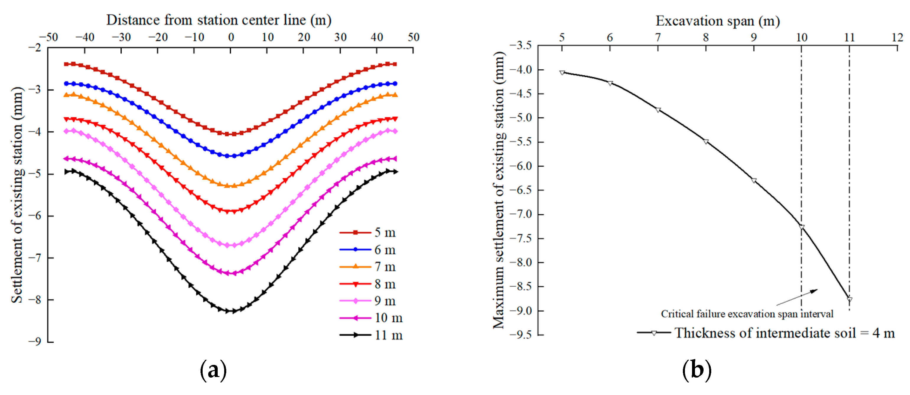
3.4. Influence of Excavation Span of the Underground Tunnel on the Settlement of Existing Station

The effects of different excavation spans on the settlement of existing stations are also different, which affects the settlement deformation of the existing structures. To examine the influence of different excavation spans on the settlement of existing stations, finite element models with excavation spans of 5, 6, 7, 8, 9, 10, and 11 m were established, and the settlement deformation maps of existing stations at different excavation spans were extracted for comparative analysis (Figure 16).
As shown in Figure 16, when the excavation span was 5 m, the maximum settlement at the existing station was 4.05 mm. When the excavation span was 11 m, the maximum settlement at the existing station was 8.26 mm. With an increase in the excavation span, the settlement of the existing station gradually increased, and the increasing trend is accelerated.
To determine the effect of different excavation spans on the settlement of the existing stations, a cloud diagram of the plastic zone of the intermediate soil was extracted, as shown in Figure 17.
As shown in Figure 17, when the excavation span was 5 m, the plastic zone of the intermediate soil was mainly concentrated above the excavation area and had not yet penetrated the entire intermediate soil. Meanwhile, the intermediate soil was partially damaged and had a partial bearing capacity that could be controlled by passive reinforcement of the intermediate soil. When the excavation span was 11 m, the plastic zone penetrated the intermediate soil layer; the intermediate soil was completely damaged and lost all its bearing capacity. Therefore, the compensation jacking method must be used to control the settlement of existing stations. A larger excavation span results in a larger slenderness ratio of the intermediate soil, which is then easier to destroy. This causes a large settlement of the existing structure.

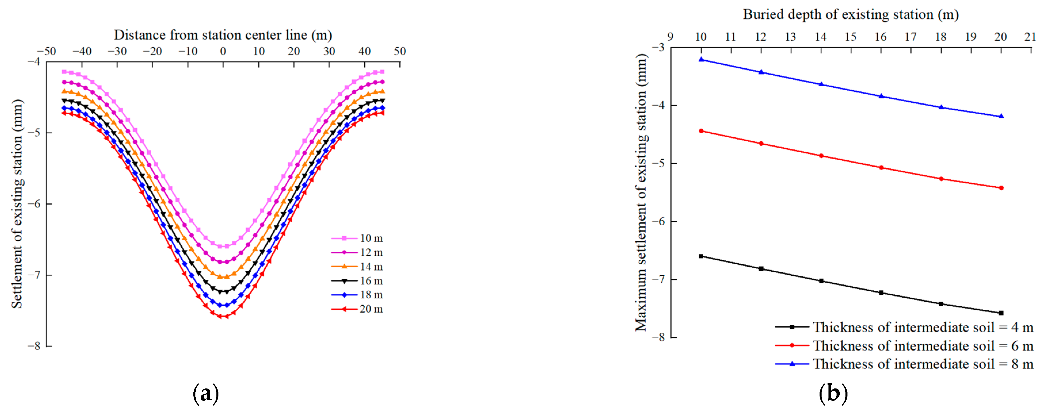
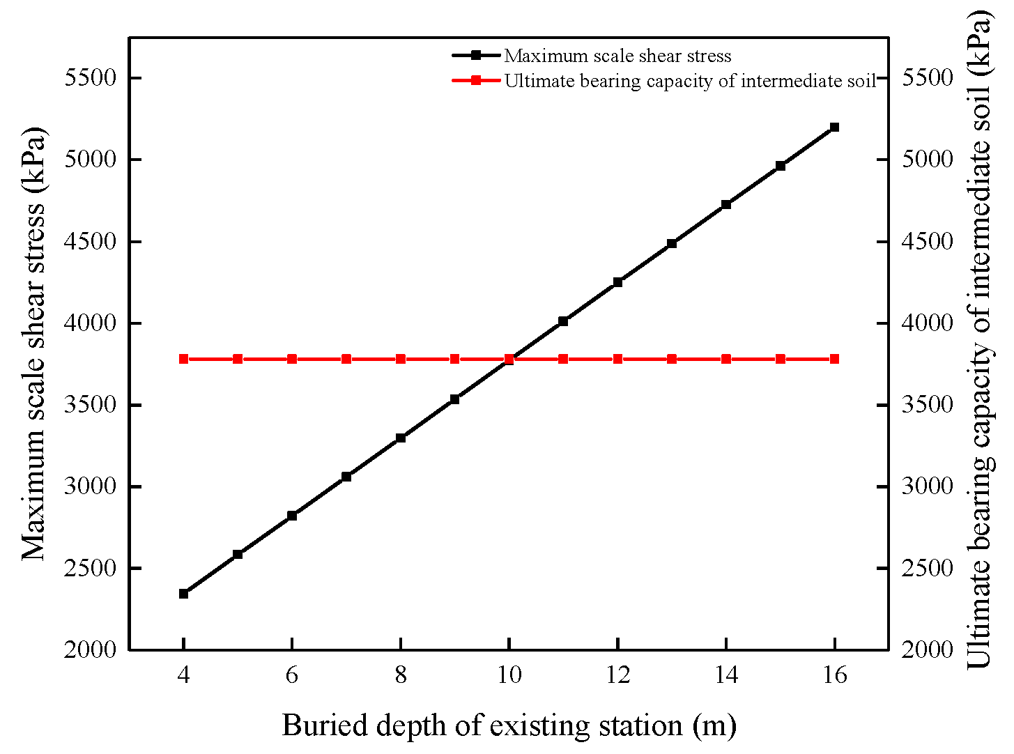
3.5. Influence of Buried Depth of Station on Settlement of Existing Station

To further explore the factors influencing the settlement of the existing station, finite element models of the station buried at depths of 10, 12, 14, 16, 18, and 20 m were established, and the settlement deformation maps of the existing station under different buried depths were extracted (Figure 18).
As shown in Figure 18, the buried depth of the station significantly affected the settlement deformation of the existing structure. A good linear relationship existed between the buried depth of the station and the settlement of the existing structure. When the buried depth of the existing station was 10 m, the maximum settlement of the existing station was 6.7 mm. When the buried depth of the existing station was 20 m, the maximum settlement of the existing station was 7.6 mm. Under the condition of same thickness of the intermediate soil, the relationship between the buried depth and the settlement of different existing stations is consistent. As the buried depth of the existing station increased, the settlement deformation of the existing station gradually increased.
To determine the influence of the buried depth of different stations on the settlement of existing stations, a cloud map of the plastic zone of the intermediate soil was extracted (Figure 19).
As shown in Figure 19, when the buried depth of the existing station was 10 m, the plastic zone of the intermediate soil was not penetrated; it still had a partial bearing capacity and presented a partial failure state. However, when the buried depth was 25 m, the plastic zone of the intermediate soil was severely damaged, the bearing capacity was considerably low, and the intermediate soil was in a completely failed state. With an increase in the buried depth of the existing station, the load on the station and intermediate soil is larger, and the damaged area of the intermediate soil is larger, resulting in a larger settlement of the existing station. According to the change in the plastic zone of the intermediate soil at different buried depths, the buried depth of the existing station affected the development of the plastic zone of the intermediate soil during excavation. In particular, a larger buried depth led to more evident damage to the intermediate soil. However, because an existing station can bear an upper load, the buried depth is not sensitive to damage in the intermediate soil.

4. Intermediate Soil Damage Identification Method

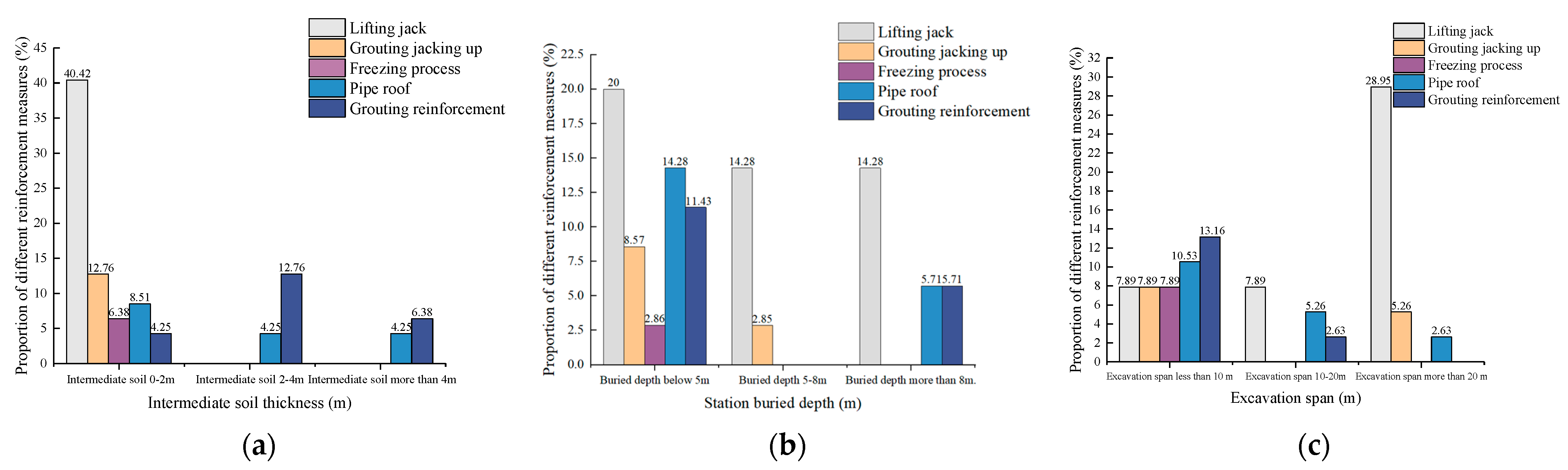
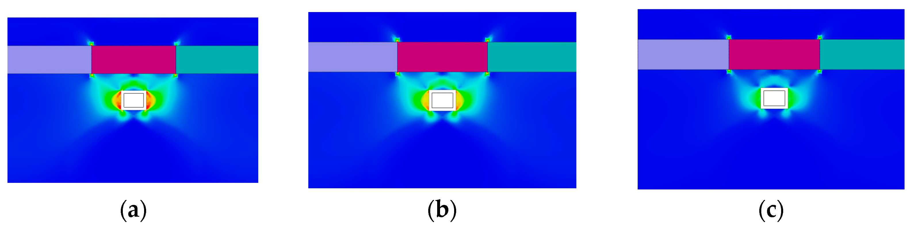
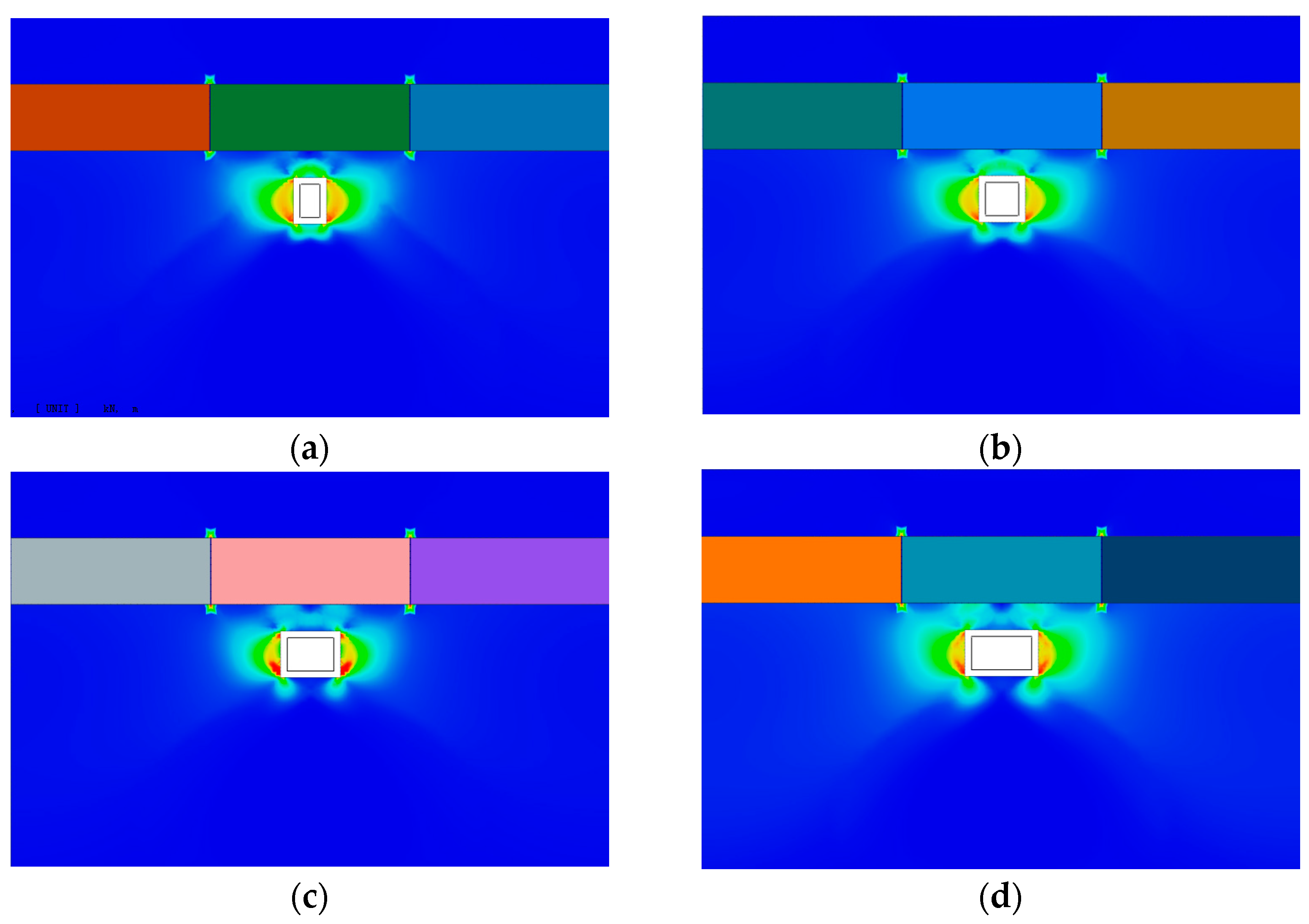
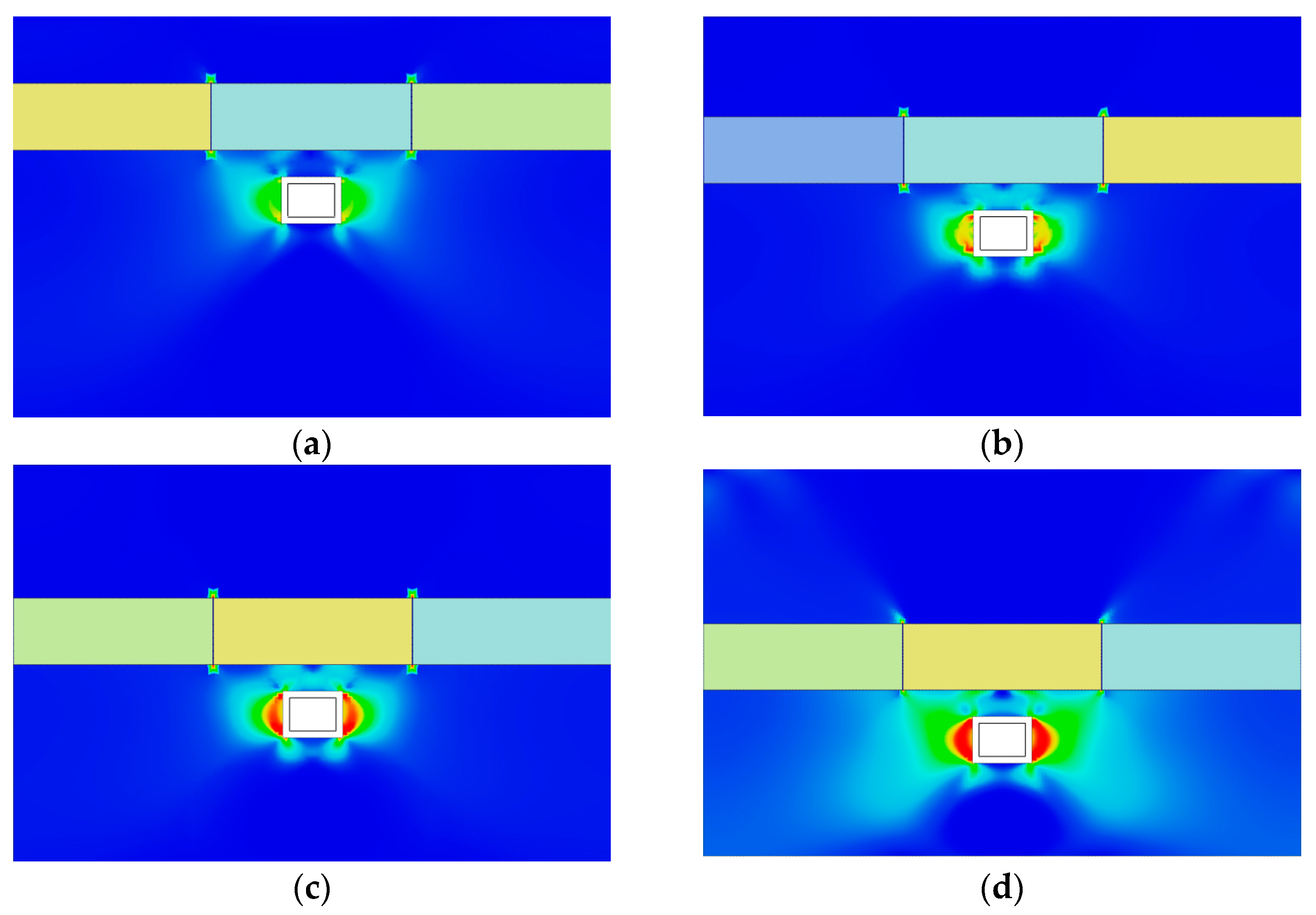
4.1. Relationship between Failure Mode of the Intermediate Soil and the Reinforcement Method

Numerical simulations showed that the failure mode of the intermediate soil can be divided into complete and partial failures. After the intermediate soil was completely destroyed, the bearing capacity of the existing structure was lost, and the settlement of the existing structure increased. When the intermediate soil was completely destroyed, the intermediate soil was unable to bear the upper load even after it was reinforced. Therefore, the settlement control of existing stations should adopt a method of compensation jacking. Passive soil reinforcement measures should be adopted when intermediate soil is partially destroyed. By reinforcing the intermediate soil, the bearing capacity is improved, and the settlement of the existing structure is reduced. Therefore, the determination of the stress state of the intermediate soil is crucial for the formulation of settlement measures for existing stations.
In practical engineering applications, the geological conditions of various projects vary. Determining whether the intermediate soil is damaged on the basis of the thickness of the intermediate soil, buried depth of the existing station, excavation span, and mechanical parameters of the soil may be inaccurate. Hence, a mechanical model of the intermediate soil was established, which was related to the strength index of the intermediate soil, to determine the failure mode of the intermediate soil, and the corresponding reinforcement control measures can be considered.

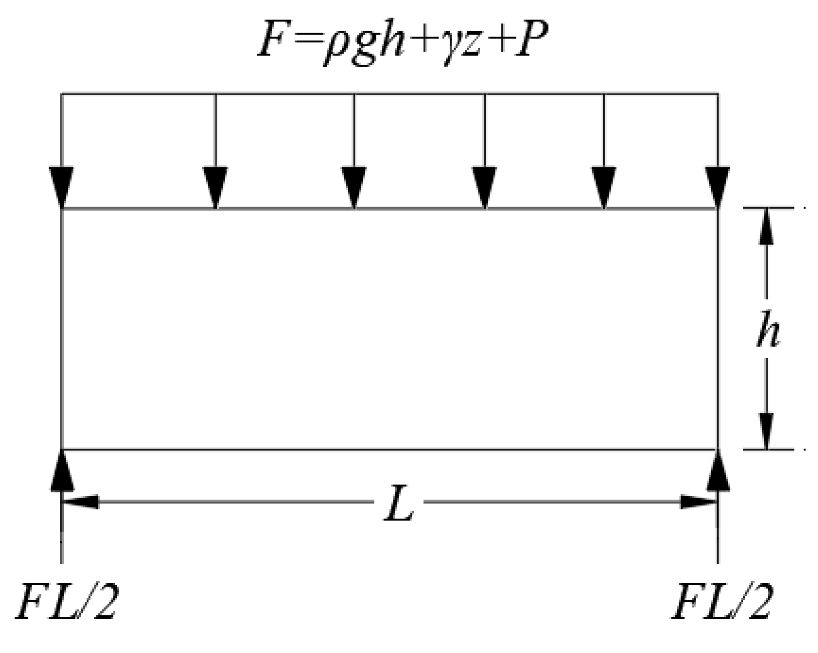
4.2. Intermediate Soil Mechanics Model

After the excavation of the new station, although the lining project has not yet been conducted, the simplified method can be used to calculate the situation of the intermediate soil. This method simplifies the intermediate soil into an upper beam that is affected only by the gravity and formation pressure of the existing station, and the soil around the lower excavation area provides vertical support. Simultaneously, the self-weight of the intermediate soil can be simplified into a uniform load acting on the beam according to the conversion method of the constant body and surface forces in elastic mechanics [43,44,45]. Finally, a mechanical model of the intermediate soil is obtained (Figure 20) [46].
For a constant intermediate soil thickness, the weight of the soil is a fixed value. According to the provisions of elastic mechanics, when the body force appears in the form of a constant, if the stress is used to solve the boundary problem, each stress component must satisfy the equilibrium differential equation:
σ x x + τ x y y + f x = 0 σ y y + τ x y x + f y = 0 .
After solving Equation (1), the full solution of the equilibrium differential equation can be obtained as
σ x = 2 Φ y 2 f x x σ y = 2 Φ x 2 f y y , τ x y = 2 Φ y x
where Φ is Airy stress function. Considering a constant body force, Φ is used as the equation for an unknown function. Φ can be solved by the stress function method, and the compatibility equation expressed by stress function can be obtained as follows:
4 Φ x 4 + 2 4 Φ x 2 y 2 + 4 Φ y 4 = 0 .
According to the theory of material mechanics, the stress components σx, σy, and τxy are mainly caused by bending moment, shear force, and load F, respectively. According to the intermediate soil mechanics model σy is a function of y.
σ y = f ( y ) .
Substituting Equation (4) into Equation (2) gives
2 Φ x 2 = f ( y ) .
The stress function form is obtained by integrating x as
Φ = x 2 2 f ( y ) + x f 1 ( y ) + f 2 ( y ) .
By substituting Equation (6) into the compatibility equation, we can obtain the following:
1 2 d 4 f ( y ) d y 4 x 2 + d 4 f 1 ( y ) d y 4 x + d 4 f 2 ( y ) d y 4 x + 2 d 2 f ( y ) d y 2 = 0 .
Equation (7) is a quadratic equation of x, and the stress function must satisfy the compatibility equation; therefore, the coefficient and free term of Equation (7) are zero. That is,
d 4 f ( y ) d y 4 = 0 d 4 f 1 ( y ) d y 4 = 0 . d 4 f 2 ( y ) d y 4 + 2 d 2 f ( y ) d y 2 = 0
The expressions for f(y), f1(y), and f2(y) can be obtained by solving for the three equalities in Equation (8).
f 1 ( y ) = E y 3 + F y 2 + G y f 2 ( y ) = A 10 y 5 B 6 y 4 + H y 3 + K y 2 . f 2 ( y ) = A 10 y 5 B 6 y 4 + H y 3 + K y 2
By substituting Equation (9) into Equation (6), the expression for the stress function can be obtained as
Φ = x 2 2 ( A y 3 + B y 2 + C y + D ) + x ( E y 3 + F y 2 + G y ) A 10 y 5 B 6 y 4 + H y 3 + K y 2 .
Substituting Equation (10) into Equation (2), the expression for each stress component is obtained as follows:
σ x = x 2 2 ( 6 A y + 2 B ) + x ( 6 E y + 2 F ) A y 3 2 B y 2 + 6 H y + 2 K σ y = A y 3 + B y 2 + C y + D . τ x y = x ( 3 A y 2 + 2 B y + C ) ( 3 E y 2 + 2 F y + G )
According to the boundary conditions of the intermediate soil mechanics model and the principle of the Saint-Venant local effect, the following can be observed:
( σ y ) y = h / 2 = 0 , ( σ y ) y = h / 2 = q , ( τ x y ) y = ± h / 2 = 0 h / 2 h / 2 ( σ x ) x = L d y = 0 , h / 2 h / 2 ( σ x ) x = L y d y = 0 , h / 2 h / 2 ( τ x y ) x = L d y = F L .
According to the aforementioned conditions, the expression for the final stress component is obtained as follows:
σ x = 6 F h 3 ( L 2 x 2 ) y + F y h ( 4 y 2 h 2 3 5 ) σ y = F 2 ( 1 + y h ) ( 1 2 y h ) 2 . τ x y = 6 F h 3 x ( h 2 4 y 2 )

4.3. Intermediate Soil Failure Criterion

The intermediate soil is dominated by shear failure when the strength fails, and the strength of the intermediate soil can be analyzed using the third strength theory [38]. In this theory, the maximum shear stress is assumed to be the factor that causes the yield failure of geotechnical materials. Regardless of the stress state, the material will yield as long as the maximum shear stress at a point in the component reaches the limit value of the material yield. The corresponding equation is as follows:
τ max = 1 2 σ 1 σ 3 .
If the maximum shear stress calculated by Equation (14) exceeds the ultimate bearing capacity of the intermediate soil, the intermediate soil can be concluded to have been completely destroyed and needs to be controlled by active jacking measures. If not exceeded, the intermediate soil is in an undamaged state, and passive reinforcement measures can be used.
For the ultimate bearing capacity of the intermediate soil, Terzaghi’s theory was used to solve the following equation:
p u = c N c + q N q + 1 2 γ b N γ ,
where c is cohesion, q is the overload on both sides, q = γ d (where γ is the weight of intermediate soil and d is its thickness), and b is the width of intermediate soil. Nc, Nq, and are bearing coefficients, which can be obtained according to the friction angle (Table 3).
The failure of the intermediate soil was determined by comparing its maximum shear stress and ultimate bearing capacity. If τ max > p u is used, the intermediate soil is proven to be in a completely damaged state at this time; otherwise, no damage occurs.

5. Engineering Case Analysis

The engineering case analysis was based on the Pingguoyuan Station of Beijing Metro Line 6, it passes close to Pingguoyuan Station of Beijing Metro Line 1. The buried depth, width, and height of the existing station are 3.8, 23.4, and 14.5 m, respectively. The overlying soil was primarily plain fill with a unit weight of 18.8 kN/m3. The thickness of the intermediate soil layer was 0 m. The intermediate soil mainly consisted of pebbles with a unit weight of 21 kN/m3. The internal friction angle was 30°, and the cohesion was 20 kPa. Through stress analysis of the intermediate soil, the failure mode of the intermediate soil under specific working conditions was determined to guide the support design.
Combined with practical cases, the comparative relationship between the shear stress and ultimate bearing capacity of intermediate soil with the influence of different intermediate soil thicknesses, excavation spans, and buried depths of existing stations was analyzed (Figure 21).
As shown in Figure 21, with an increase in the thickness of the intermediate soil, the maximum shear stress showed a downward trend, which gradually decreased. When the thickness of the intermediate soil was between 0 and 2 m, the maximum shear stress of the intermediate soil exceeded the ultimate bearing capacity, the soil was destroyed, and the bearing capacity was insufficient. When the excavation span increased, the degree of damage to the intermediate soil became more severe. When the excavation span exceeded a certain range, the intermediate soil was completely destroyed. As the buried depth of the existing stations increased, the load above the intermediate soil increased. When the buried depth exceeded a certain value, the intermediate soil was severely damaged, thus requiring an external force to control the settlement deformation of the station.
By analyzing the comparative relationship between the shear stress and ultimate bearing capacity of intermediate soil under different thicknesses of intermediate soil, excavation spans, and buried depths of the existing station, the actual engineering law was found to be consistent with the numerical simulation law and the investigation results. When the thickness of the intermediate soil was less than 2 m, compensation jacking measures were required to reduce the settlement of the existing structure. When the thickness of the intermediate soil exceeded 2 m, the settlement of the station was controlled by reinforcing the soil. At the construction site, the grouting jacking method was used to control the settlement of existing stations, and good results were achieved.

6. Conclusions

Intermediate soil has a significant influence on the settlement of the existing station as a connector between the new tunnel and the existing station. The state of intermediate soil should be considered when selecting settlement control measures for existing stations. Through investigation and numerical simulation, the corresponding relationship between the state of the intermediate soil and the settlement and control measures of existing stations was analyzed, and the following conclusions were obtained:
(1)
The settlement control measures for existing stations in tunnel construction are of two main types: compensation jacking and passive reinforcement of the soil. Jacking compensates for the settlement deformation of an existing structure by applying a jacking force, and the settlement of the existing structure changes inversely. The reinforcement of the soil improves the bearing capacity of the intermediate soil, thereby reducing the settlement of the existing structure.
(2)
The settlement control measures of the existing station are closely related to the thickness of the intermediate soil and span of the tunnel excavation, which determine the bearing capacity of the intermediate soil. Thinner and longer intermediate soils have a weaker bearing capacity. Strong reinforcement measures such as compensation jacking are often used in construction. In contrast, soil reinforcement measures are often used to improve the bearing capacity of intermediate soil and control the settlement deformation of existing stations.
(3)
The numerical simulation showed that the failure mode of the intermediate soil was divided into two modes: complete and partial failures. The failure state of intermediate soil should be considered in the formulation of settlement control measures for existing stations.
(4)
The thickness of the intermediate soil, mechanical parameters of the soil, span of the new excavation, and buried depth of the existing station affected the stress state of the intermediate soil. A simple discriminant model for the failure of intermediate soils was proposed. Compensation jacking measures should be implemented to control the settlement of the existing structures during construction when the intermediate soil is completely destroyed. Passive soil reinforcement measures should be implemented when the intermediate soil is partially destroyed. The discriminant model can guide the formulation of settlement control measures for the existing stations.
(5)
In this study, some simplifications were made when formulating the intermediate soil mechanics model without considering the characteristics of the stratum, which has certain limitations. Differences were observed in the failure modes of the intermediate soil between sandy and cohesive soils. Subsequent studies should combine the characteristics of the strata to develop a more realistic stress model.

Author Contributions

Conceptualization, S.W.; methodology, S.W.; software, X.Z.; validation, S.W. and X.Z.; formal analysis, S.W. and X.Z.; resources, X.L.; visualization, D.W.; investigation, S.W. and X.Z.; supervision, J.C.; writing—original draft preparation, X.Z.; writing—review and editing, S.W.; project administration, E.L.; funding acquisition, S.W. All authors have read and agreed to the published version of the manuscript.

Funding

This research was supported by the Shandong Provincial Natural Science Foundation, China (NO. ZR2020QE265) by Shengzhi Wu and the China Railway Construction Corporation Limited 2020 Annual Research Plan Subject (NO. 2020-B05) by Shengzhi Wu, Xueyu Zhang, Xiudong Li, Jian Chen, Erbin Liang and Dun Wu.

Data Availability Statement

Not applicable.

Conflicts of Interest

The authors declare no conflict of interest.

Appendix A

Table A1. Survey table of undercrossing engineering cases.
New Built TunnelExisting StationIntermediate Soil ThicknessBuried Depth of Existing StationExcavation SpanStratumMeasureConstruction MethodSedimentation
Xuan wu men Station of Line 4Xuan wu men Station of Line 21.94.59.85Pebble gravel layer, silty clay layer, silt layerPipe roofCRD method3.45
Ping guo yuan Station of Beijing Subway Line 6Ping guo yuan Station of Beijing Metro Line 106.723.5Pebble bedScrew + grouting jackingPBA method1.909
Su zhou Street Station of Beijing Line 16Su zhou Street Station of Metro Line 1006.327.6Artificial fill soil and Quaternary sedimentary clay, silt, sand, gravel soilLifting jackPBA method2.07
Chaoyangmen Station-Dongdaqiao Station interval of Metro Line 6Chaoyangmen Station of Line 205.2222.7Round gravel pebble and silty clay layerLifting jackCRD construction method of flat top straight wall2.5
Line 16 national library station to Erligou station intervalLine 4 National Library~Zoo interval right line3.36814.8966.30Fine sand layer, pebble layerGrouting reinforcementBench cut method1.88
Gongzhufen Station of Beijing Metro Line 10Gongzhufen Station of Beijing Metro Line 105.426.1Conglomerate layer, local mudstone, pebble layerLifting jackCRD method2.98
Chongwenmen Station of Line 5Line 2 Chongwenmen~Beijing
Station interval
1.985.1624.2Silty sand stratumPipe shed + grouting jackingColumn–hole method16.75
Line 6 Dongsi~Chaoyangmen intervalLine 5 Dongsi station012.733.8Silty fine sand layer and medium coarse sand layerLifting jackCRD method2.35
Line 7 Guangqumenwai station to Shuangjing station intervalShuangjing Station of Line 10013.723.1Interbedding of confined water-rich sandLifting jackCRD method1.2
Chongwen Sanlihe Station—Ciqikou Station Section East Side of Beijing Subway Line 7Ciqikou Station of Line 50.710.135.3Pebble, medium-coarse sand, silty clay, and siltPipe roofBench cut method3
Line 6 Chegongzhuang~Ping ‘anli intervalChegongzhuang Station of Line 22.474.76.6Clay, siltGrouting reinforcementbench cut method3.08
Line 14 Anlelin~Puhuangyu intervalPuhuangyu Station of Line 50.355.856.6Sandy cobble groundGrouting jacking upCRD method1.5
Beijing Metro Line 17 Shilihe Station~Panjiayuan West Station SectionThe existing Shilihe Station of Beijing Metro Line 142.794.56.48Water-rich sand stratumGrouting reinforcementCRD method2.38
Tuanjiehu Station-Chaoyang Park Station Section of Beijing Subway Line 3Tuanjiehu transfer station of Line 10096.75Conglomerate strataLifting jackCRD method4.89
Shenzhen Metro Line 10 Futian Port Station~Fumin Station SectionFutian Port Station of Line 49.7 8.48Gravel sand, pebble soil, sandy strongly weathered granite, moderately weathered granite, slightly weathered granite, gravel sand layer above with coarse sand, muddy clayPipe roofCRD method1.98
Zhongsheng Station of Nanjing Metro Line 7Existing Zhongsheng Station of Line 100.63.29Confined water-rich sand layerFreezing reinforcement 6.97
Chengmen Station of Fuzhou Metro Line 4Existing Line 1 station08.86.8Muddy soil, residual cohesive soil, complete weatheringFreezing reinforcementCRD method3.6
Dongdaqiao Station of Metro Line 17No. 6 subway line east bridge station2.1 9.9 Pipe roofPBA method2.02
Hefei Metro Line 8Yilijing Station of Line 32.074.3 Medium weathered sandstoneGrouting reinforcementBench cut method2.39
Chengdu Metro Nijiaqiao Station New Line 8Existing Metro Line 1 Station0223.4Medium dense pebble soil layer, strongly weathered mudstoneLifting jackCRD method4.84
Tianfu Business District Station of Chengdu Metro Line 19Tianfu Business District Station of Chengdu Metro Line 60428.6Middle weathered mudstone strataTemporary supportBench cut method4.6
Zhengzhou Metro Line 4 Exhibition Center StationLine 1 exhibition
Central station
0623.7Silt–sand layerSleeve liftBench cut method2.2
Xinjianciqu Station of Beijing Metro Line 17Yizhuang line Ciqu station039.5Sandy silt and silty clay, locally sandwiched thin layer of clayey silt PBA method
Xuzhou City Line 6Line 2 municipal government station05.66.41Sandy silt layerPipe roof + grouting reinforcementCRD method
Chengdu Metro Line 9 TunnelIncubation Park Station of Chengdu Metro Line 12.34.18.5Pebble soil, strongly weathered mudstonePipe roofCRD method4
Hefei Rail Transit Line 7Zilu Station of Line 103.114Clay and silty clay layer, no sand layer or other permeable layerPipe roofCRD method2.2
Beijing rail transit capital airport line west extension project Dongzhimen station to Beixinqiao station intervalDongzhimen station of existing M2 line08.89.6 Lifting jackPBA method4.8
Yungu Road Station-Huashan Station of Hefei Rail Transit Line 5existing station1.9888 8.2Weak expansion potential clay layerGrouting reinforcementCRD method7
Shenyang New Line 9Line 1 Shenyang Tiexi Square Station03.4812.9 3.3
Chongqing North Railway StationExisting Line 3 station7.21.515Filling, sandy mudstone, sandstonePipe roofBench cut method1.75
Guomao Station-Shuangjing Station Section of Beijing Subway Line 10Existing Line 11.212.38.2Sandy cobble groundSteel supportCRD method4.77
A new subway in Hangzhouexisting station03.16.94Muddy silty clay, silty clayMjs reinforcement + lifting jackCRD method6
Beijing metro line 19 intervalXingong Station of Line 40.223.213.5Pebble gravel stratumFull framingCRD method3
Shenzhen Metro Line 7Fumin Station of Line 403.66.6Gravel cohesive soil, sandy soilGrouting jacking upCRD method2.03
Guoquan Road Station-Fudan University Station Section of Shanghai Rail Transit Line 18Rail transit line 10 Guoquan Road station2 7.7Clay, silty clay, water-richFreezing reinforcementMining method8.4
Beijing rail transit capital airport lineBeixin Bridge of Line 5Station03.311.9Silty clay, fine sand, pebble layerGrouting jacking upPBA method5.1
Chengdu Line 5, Sichuan ProvinceProvincial People ‘s Hospital Station of University of Traditional Chinese Medicine0 6.8Dense sand pebble layer CRD method
Baoan District Reclamation Area Line 1 ProjectSanhaojie Station of Line 58.16 Residual cohesive soil, granite completely strong weathering level in weatheringGrouting reinforcementBench cut method6.2
Intermediate Station of Chengdu Rail Transit Line 13 Phase I ProjectExisting stations of Line 702.623.2Dense pebble layerLifting jackCRD method5.2
Metro Line 9 Olympic Sports Center Station~Olympic Sports East StationExisting Line 2 Olympic Sports Center Station03.520.5Miscellaneous fill, silty clay, gravel sand, round gravelLifting jackBench cut method2.43
Shanghai Road Station of Nanjing Metro Line 5Shanghai Road Station of existing Metro Line 202.313Silty clay mixed with silt, pebble-containing silty clay and strong and medium weathered gluteniteLifting jackBench cut method2.9
Kunming new subway line 4 Liandajie station-Kunming south railway station intervalLiandajie Station of Kunming Metro Line 12 Clay, silty clay layerGrouting reinforcementCRD method6
Shanghai S line subwayexisting station03.5 Silty clay layerLifting jackPBA method2.35
South-to-North Water Diversion culvertWukesong Station of Line 13.6674.834.2silty fine sand, boulder flintGrouting reinforcementBench cut method4.83
Park Front Station of Guangzhou Metro Line 2Existing Line 1 station01 Miscellaneous fill, silty clay, strong, medium and slightly weathered bedrock (siltstone with pebbly sandstone)Horizontal beam plate and steel pipe connectionCover-excavation inverse construction method13.8
Satellite Square Station of Changchun Metro Line 1Light rail line 3 project0521.7Miscellaneous fill, silty clay, clay, weathered mudstoneLifting jackPBA method9.5
Beijing Road Station of Guiyang Metro Line 3rail transit line 10015.5Miscellaneous fill, red clay, Triassic Anshun Formation dolomiteSteel cylindrical columnArch cover pillar method
Qianhaiwan Station-Bao‘an Station Section of Shenzhen Rail Transit Line 11 ProjectBaohua Station on Line 58.163.35 Residual cohesive soil, granite fully strong weathered layer and medium weathered, slightly weathered zoneGrouting reinforcementStep method initial support + shield segment6.1
Chongqing Rail Line 10Hongtudi Station of Rail Line 65.06 11.54Sandy mudstone, sandstone, sandy mudstone strataGrouting reinforcementCRD method8.42

References

  1. Broere, W. Urban underground space: Solving the problems of today’s cities. Tunn. Undergr. Space Technol. 2016, 55, 245–248. [Google Scholar]
  2. Addenbrooke, T.I.; Potts, D.M. Twin Tunnel Interaction: Surface and Subsurface Effects. Int. J. Geomech. 2001, 1, 249–271. [Google Scholar]
  3. Ding, Z.; Zhang, M.-B.; Zhang, X.; Wei, X.-J. Theoretical analysis on the deformation of existing tunnel caused by under-crossing of large-diameter slurry shield considering construction factors. Tunn. Undergr. Space Technol. Inc. Trenchless Technol. Res. 2023, 133, 104913. [Google Scholar] [CrossRef]
  4. Avgerinos, V.; Potts, D.M.; Standing, J.R. Numerical investigation of the effects of tunnelling on existing tunnels. Géotechnique 2017, 67, 808–822. [Google Scholar] [CrossRef]
  5. Hou, Y.; Zhang, D.; Chen, F. Study of mechanism and prediction of grouting uplift in tunnel construction undercrossing buildings. Chin. J. Rock Mech. Eng. 2011, 30, 2407–2415. [Google Scholar]
  6. Lai, H.; Zheng, H.; Chen, R.; Kang, Z.; Liu, Y. Settlement behaviors of existing tunnel caused by obliquely under-crossing shield tunneling in close proximity with small intersection angle. Tunn. Undergr. Space Technol. 2020, 97, 103258. [Google Scholar] [CrossRef]
  7. Jin, D.; Yuan, D.; Liu, S.; Li, X.; Luo, W. Performance of Existing Subway Tunnels Undercrossed by Four Closely Spaced Shield Tunnels. J. Perform. Constr. Facil. 2019, 33, 04018099. [Google Scholar] [CrossRef]
  8. Ma, S.; Li, M.; Jin, J.; Bai, K. The influence of shallow buried double-line parallel rectangular pipe jacking construction on ground settlement deformation. Alex. Eng. J. 2021, 60, 1911–1916. [Google Scholar]
  9. Jia, L. Study on the Effects of New Metro Station Crossing under the Existing Peculiar Metro Station in Small Distance. Ph.D. Thesis, Beijing University of Civil Engineering and Architecture, Beijing, China, 2016. [Google Scholar]
  10. Li, P.; Du, S.-J.; Ma, X.-F.; Yin, Z.-Y.; Shen, S.-L. Centrifuge investigation into the effect of new shield tunnelling on an existing underlying large-diameter tunnel. Tunn. Undergr. Space Technol. 2014, 42, 59–66. [Google Scholar] [CrossRef]
  11. Qi, Y.; Wei, G.; Xie, Y. Method of Calculating the Vertical Displacement and Additional Stress of Existing Tunnels under the Influence of Grouting Rings of New Tunnels. Symmetry 2020, 12, 1623. [Google Scholar]
  12. Wang, H.N.; Gao, X.; Wu, L.; Jiang, M.J. Analytical study on interaction between existing and new tunnels parallel excavated in semi-infinite viscoelastic ground. Comput. Geotech. 2020, 120, 103385. [Google Scholar]
  13. Gokuldas, S.; Banerjee, S.; Nimbalkar, S.S. Effects of Tunneling-Induced Ground Movements on Stability of Piled Raft Foundation: Three-Dimensional Finite-Element Approach. Int. J. Geomech. 2020, 20, 04020104. [Google Scholar]
  14. Zhou, L.; Zhu, Y. Analysis of Stratum Settlement Laws Caused by the Construction of Shallow-Buried Expressway Tunnels with Large Span and Small Spacing. Geotech. Geol. Eng. 2021, 39, 1485–1495. [Google Scholar]
  15. Mirhabibi, A.; Soroush, A. Three-Dimensional Simulation of Interaction between Surface Buildings and Twin Tunnelling Regarding the Surface Settlement. Geotech. Geol. Eng. 2020, 38, 5143–5166. [Google Scholar]
  16. Yang, H.; Shi, H.; Jiang, X.; Liu, C.; Yu, L. Study on Influence of Construction Process of Double-Line Shield Tunnels on Frame Structure. Geotech. Geol. Eng. 2021, 39, 1465–1484. [Google Scholar] [CrossRef]
  17. Zhou, F.; Zhou, P.; Li, J.; Lin, J.; Ge, T.; Deng, S.; Ren, R.; Wang, Z. Deformation characteristics and failure evolution process of the existing metro station under unilateral deep excavation. Eng. Fail. Anal. 2022, 131, 105870. [Google Scholar]
  18. Liang, R.; Xia, T.; Hong, Y.; Yu, F. Effects of above-crossing tunnelling on the existing shield tunnels. Tunn. Undergr. Space Technol. Inc. Trenchless Technol. Res. 2016, 58, 159–176. [Google Scholar]
  19. Li, Y.; Zhou, G.; Tang, C.; Wang, S.; Wang, K.; Wang, T. Influence of undercrossing tunnel excavation on the settlement of a metro station in Dalian. Bull. Eng. Geol. Environ. 2021, 80, 4673–4687. [Google Scholar] [CrossRef]
  20. Sharma, J.; Hefny, A.; Zhao, J.; Chan, C. Effect of large excavation on deformation of adjacent MRT tunnels. Tunn. Undergr. Space Technol. Inc. Trenchless Technol. Res. 2001, 16, 93–98. [Google Scholar]
  21. Zhang, Z.; Huang, M. Geotechnical influence on existing subway tunnels induced by multiline tunneling in Shanghai soft soil. Comput. Geotech. 2014, 56, 121–132. [Google Scholar]
  22. Lin, Z.; Chen, X.; Yang, H.; Cheng, C.; Wang, H.; Yang, C.; Zhu, G. Experimental Study on Structural Form and Excavation Model of Urban Metro Cross Transfer Station with Super Large Cross Section and Shallow Excavation. Adv. Civ. Eng. 2020, 2020, 9723927. [Google Scholar]
  23. Fang, Q.; Zhang, D.; Li, Q.; Wong, L.N.Y. Effects of twin tunnels construction beneath existing shield-driven twin tunnels. Tunn. Undergr. Space Technol. Inc. Trenchless Technol. Res. 2015, 45, 128–137. [Google Scholar]
  24. Ng, C.W.W.; Boonyarak, T.; Mašín, D. Three-dimensional centrifuge and numerical modeling of the interaction between perpendicularly crossing tunnels. Can. Geotech. J. 2013, 50, 935–946. [Google Scholar] [CrossRef]
  25. Liu, X.; Fang, Q.; Zhang, D. Mechanical responses of existing tunnel due to new tunnelling below without clearance. Tunn. Undergr. Space Technol. 2018, 80, 44–52. [Google Scholar] [CrossRef]
  26. Liu, X.; Fang, Q.; Zhang, D.; Liu, Y. Energy-based prediction of volume loss ratio and plastic zone dimension of shallow tunnelling. Comput. Geotech. 2020, 118, 103343. [Google Scholar] [CrossRef]
  27. Li, X.; Zhang, C.; Yuan, D. An in-tunnel jacking above tunnel protection methodology for excavating a tunnel under a tunnel in service. Tunn. Undergr. Space Technol. Inc. Trenchless Technol. Res. 2013, 34, 22–37. [Google Scholar]
  28. Wu, K.; Shao, Z. Effects of Pipe Roof Support and Grouting Pre-Reinforcement on the Track Settlement. Adv. Civ. Eng. 2018, 2018, 6041305. [Google Scholar]
  29. Kummerer, C.; Schweiger, H.F.; Otterbein, R. Active Settlement Control with Compensation Grouting—Results from a Case Study. In Proceedings of the International Conference on Grouting & Ground Treatment, New Orleans, LA, USA, 10–12 February 2003; pp. 813–823. [Google Scholar]
  30. Huo, R.; Zhou, P.; Song, Z.; Wang, J.; Li, S.; Zhang, Y. Study on the settlement of large-span metro station’s baseplate caused by the tunnels newly built beneath it. Adv. Mech. Eng. 2019, 11, 1687814018825161. [Google Scholar] [CrossRef] [Green Version]
  31. Zhang, X.; Zhang, C.; Wang, J. Effect of Closely Spaced Twin Tunnel Construction beneath an Existing Subway Station: A Case Study. J. Test. Eval. 2018, 46, 1559–1573. [Google Scholar]
  32. Li, J.; Li, J.; Cai, Y.; Wu, D.; Guo, C.; Zhao, W.; Tang, K.; Liu, Y. Application of Artificial Freezing Method in Deformation Control of Subway Tunnel. Adv. Mater. Sci. Eng. 2022, 2022, 3251318. [Google Scholar]
  33. Zheng, Y.; Wu, K.; Sun, J.; Chen, R.; Li, Y.; Yang, S. Study on the Influence of Close Distance Construction of Urban Tunnel on the Existing Station. Geotech. Geol. Eng. 2021, 39, 4765–4780. [Google Scholar] [CrossRef]
  34. Zhao, C.; Lei, M.; Shi, C.; Cao, H.; Yang, W.; Deng, E. Function mechanism and analytical method of a double layer pre-support system for tunnel underneath passing a large-scale underground pipe gallery in water-rich sandy strata: A case study. Tunn. Undergr. Space Technol. 2021, 115, 104041. [Google Scholar]
  35. Fu, H.; An, P.; Huang, Z.; Zhang, J.; Shi, Y.; Yao, G. Determination of safety distance of twin tunnel underpassing existing tunnels. In Advances in Environmental Vibration and Transportation Geodynamics: Proceedings of ISEV 2018; Springer: Singapore, 2020; pp. 839–848. [Google Scholar]
  36. Hage Chehade, F.; Shahrour, I. Numerical analysis of the interaction between twin-tunnels: Influence of the relative position and construction procedure. Tunn. Undergr. Space Technol. 2007, 23, 210–214. [Google Scholar]
  37. Shahin, H.M.; Nakai, T.; Ishii, K.; Iwata, T.; Kuroi, S. Investigation of influence of tunneling on existing building and tunnel: Model tests and numerical simulations. Acta Geotech. 2016, 11, 679–692. [Google Scholar]
  38. Zhang, X.; Zhang, C.; Han, K.; Wang, J. Case study of control technology of structural settlements due to tunnelling beneath a subway station. Chin. J. Geotech. Eng. 2017, 39, 759–766. [Google Scholar]
  39. Zhang, Z.; Liu, Z.; Zheng, K. Optimization construction process of PBA new station pilot tunnels under the existing station. Build. Struct. 2020, 50, 882–887. [Google Scholar]
  40. Zhang, C.; Zhang, D.; Wang, M. Structural deformation of overlying subway tunnels induced by tunnelling. Chin. J. Rock Mech. Eng. 2009, 31, 805–810. [Google Scholar]
  41. Wang, J.; Li, X.; Wu, S.; He, Z.; Wei, Y. Field test and numerical simulation of ground settlement in super shallow buried station excavation supported by transverse pipe roof. Front. Earth Sci. 2023, 11, 1136270. [Google Scholar]
  42. Wu, S.; Xie, H.; Zeng, Z.; Wang, M.; Zhao, H.; Liu, Y. Influence of Pea-Gravel Layer on Segment Ring Support Performance in Shield TBM Tunnels: A Discrete-Continuous Coupling Simulation and Model Test. J. Constr. Eng. Manag. 2023, 149, 04023097. [Google Scholar] [CrossRef]
  43. Liu, X.; Fang, Q.; Zhang, D.; Wang, Z. Behaviour of existing tunnel due to new tunnel construction below. Comput. Geotech. 2019, 110, 71–81. [Google Scholar] [CrossRef]
  44. Xu, T. Study on Mechanical Evolution and Design Method of Undercut Multi-Ayered Tunnel Groups. Ph.D. Thesis, Southwest Jiaotong University, Chengdu, China, 2019. [Google Scholar] [CrossRef]
  45. Niu, X. Engineering Response and Control of Existing Tunnel Structure with Long Distance Close Bonding and Parallel Undercrossing. Ph.D. Thesis, Beijing Jiaotong University, Beijing, China, 2018. [Google Scholar]
  46. Bai, Q.; Zhang, Y.; Zhao, W.; Jia, P.; Li, S.; Wang, Z. Construction of subway station using the small pipe roof-beam method: A case study of Shifu Road station in Shenyang. Tunn. Undergr. Space Technol. 2023, 135, 105000. [Google Scholar]
Figure 1. Proportion of reinforcement measures with different influential factors. (a) Relationship diagram between the thickness of intermediate soil and the proportion of reinforcement measures. (b) Relationship diagram between the buried depth of the station and the proportion of reinforcement measures. (c) Relationship diagram between excavation span and the proportion of reinforcement measures.
Buildings 13 01933 g001
Figure 2. Relationship between settlement and reinforcement measures of existing station. (a) Scatter plot of settlement and reinforcement measures of existing stations with different intermediate soil thicknesses. (b) Scatter plot of settlement and reinforcement measures of existing stations with different buried depths of stations. (c) Scatter plot of settlement and reinforcement measures of existing station with different excavation spans.
Buildings 13 01933 g002
Figure 3. Settlement curve of the existing station with jack lifting (image by Zhang). (a) Settlement duration curve of the existing station structure with jack lifting. (b) Settlement curve of the existing station by varying the jack-lifting force.
Buildings 13 01933 g003
Figure 4. Settlement diagram of existing station under the action of grouting jacking (image by Zhang and Hou). (a) Settlement duration curve of the existing subway structure with grouting jacking. (b) Settlement curve of existing structure with different grouting pressures.
Buildings 13 01933 g004
Figure 5. Vertical deformation curve of the existing tunnel with a pipe roof support (image by Zhang).
Buildings 13 01933 g005
Figure 6. Deformation of pipe roof and that of soil arch between the pipes when bearing the load. (a) Soil-arch deformation diagram between pipe roofs. (b) Deformation diagram of the pipe roof (image by Wang [41]). Blue indicates that the plastic zone is not damaged. Green represents the range of plastic zone damage. Red represents the most severe damage to the plastic zone.
Buildings 13 01933 g006
Figure 7. Finite element model of the tunnel beneath the existing station.
Buildings 13 01933 g007
Figure 8. Settlement deformation of the existing station with different intermediate soil thicknesses. (a) Settlement curve of the existing station with different intermediate soil thickness. (b) Relationship curve between the maximum settlement of the existing station and the thickness of the intermediate soil.
Buildings 13 01933 g008
Figure 9. Distribution of plastic zone with different intermediate soil thicknesses. (a) Close penetration. (b) Thickness of intermediate soil = 2 m. (c) Thickness of intermediate soil = 4 m. (d) Thickness of intermediate soil = 6 m. (e) Thickness of intermediate soil = 8 m. (f) Thickness of intermediate soil = 10 m. (g) Thickness of intermediate soil = 15 m. Blue indicates that the plastic zone is not damaged. Green represents the range of plastic zone damage. Red represents the most severe damage to the plastic zone.
Buildings 13 01933 g009
Figure 10. Settlement deformation of the existing station with different elastic moduli. (a) Settlement curve of the existing station with different elastic moduli of the intermediate soil. (b) Relationship curve between the maximum settlement of the existing station and the elastic modulus of intermediate soil.
Buildings 13 01933 g010
Figure 11. Distribution of elastic modulus plastic zone in different soil layers: (a) E = 80 MPa; (b) E = 120 MPa; (c) E = 160 MPa. Blue indicates that the plastic zone is not damaged. Green represents the range of plastic zone damage. Red represents the most severe damage to the plastic zone.
Buildings 13 01933 g011
Figure 12. Settlement deformation of existing stations at different cohesion values. (a) Settlement curve of the existing station with different cohesion values of intermediate soil. (b) Relationship curve between the maximum settlement of the existing station and the cohesion of the intermediate soil.
Buildings 13 01933 g012
Figure 13. Distribution of cohesive plastic zone in different soil layers: (a) cohesion = 30 kN/m²; (b) cohesion = 60 kN/m²; (c) cohesion = 90 kN/m². Blue indicates that the plastic zone is not damaged. Green represents the range of plastic zone damage. Red represents the most severe damage to the plastic zone.
Buildings 13 01933 g013
Figure 14. Settlement deformation of existing station at different internal friction angles. (a) Settlement curve of the existing station with different intermediate soil friction angles. (b) Relationship curve between the maximum settlement of the existing station and the friction angle of intermediate soil.
Buildings 13 01933 g014
Figure 15. Distribution of friction angle plastic zone in different soil layers: (a) friction angle = 22°; (b) friction angle = 26°; (c) friction angle = 30°. Blue indicates that the plastic zone is not damaged. Green represents the range of plastic zone damage. Red represents the most severe damage to the plastic zone.
Buildings 13 01933 g015
Figure 16. Settlement deformation of the existing station with different excavation spans. (a) Settlement curve of the existing station with different excavation spans. (b) Relationship curve between the maximum settlement of existing station and the excavation span.
Buildings 13 01933 g016
Figure 17. Plastic zone distribution of different excavation spans: (a) excavation span = 5 m; (b) excavation span = 7 m; (c) excavation span = 9 m; (d) excavation span = 11 m. Blue indicates that the plastic zone is not damaged. Green represents the range of plastic zone damage. Red represents the most severe damage to the plastic zone.
Buildings 13 01933 g017
Figure 18. Settlement deformation of the existing station with different buried depths. (a) Settlement curve of the existing station with different buried depths of the station. (b) Relationship curve between the maximum settlement and the buried depth of the existing station.
Buildings 13 01933 g018
Figure 19. Distribution of plastic zone at different buried depths: (a) buried depth = 10 m; (b) buried depth = 16 m; (c) buried depth = 20 m; (d) buried depth = 25 m. Blue indicates that the plastic zone is not damaged. Green represents the range of plastic zone damage. Red represents the most severe damage to the plastic zone.
Buildings 13 01933 g019
Figure 20. Model for intermediate soil mechanics. In the model, F is the resultant force of the intermediate soil, ρ is the density of the intermediate soil, g is the acceleration owing to gravity, h is the thickness of the intermediate soil, γ is the weight of the overlying soil, z is the buried depth, and P is the weight of the existing station.
Buildings 13 01933 g020
Figure 21. Comparison of maximum shear stress and the ultimate bearing capacity of intermediate soil with different influential factors.
Buildings 13 01933 g021aBuildings 13 01933 g021b
Table 1. Soil parameters.
NamePoisson RatioVolumetric Weight kN/m3Triaxial Test Secant Stiffness kN/m2Tangent Stiffness of Main Compaction Loading Test
kN/m2
Unloading Elastic Modulus kN/m2Angle of Friction at Shear FailureCohesion
kN/m2
Final Expansion Angle
Stratum0.3518.854,00045,000135,00025°28
Table 2. Station model parameters.
NameElastic Modulus MPaPoisson RatioUnit Weight kg/m3
Primary support30,0000.22300
Secondary liner32,5000.252500
Existing station32,5000.252500
Table 3. Terzaghi’s equation for bearing capacity coefficient.
φ/(°)NγNqNc
001.05.7
101.22.79.5
205.07.417.6
302022.437.0
4013080.594.8
Disclaimer/Publisher’s Note: The statements, opinions and data contained in all publications are solely those of the individual author(s) and contributor(s) and not of MDPI and/or the editor(s). MDPI and/or the editor(s) disclaim responsibility for any injury to people or property resulting from any ideas, methods, instructions or products referred to in the content.

