Article

Behaviour of Steel-Concrete-Steel Sandwich Beams with Novel Enhanced C-Channels

by
Ananthakumar Ayyadurai
1,*,
Balaji Shanmugam
2 and
Gobinath Ravindran
3
1
Department of Civil Engineering, Vivekanandha College of Technology for Women, Namakkal 637205, Tamilnadu, India
2
Department of Civil Engineering, Kongu Engineering College, Erode 638060, Tamilnadu, India
3
Department of Civil Engineering, SR University, Warangal 506371, Telangana, India
*
Author to whom correspondence should be addressed.
Buildings 2023, 13(8), 1956; https://doi.org/10.3390/buildings13081956
Submission received: 5 June 2023 / Revised: 25 July 2023 / Accepted: 29 July 2023 / Published: 31 July 2023
(This article belongs to the Section Building Materials, and Repair & Renovation)

Abstract

:
As the load increases, most composite beams generally experience failure in both shear and flexural behavior. This outcome highlights the critical challenges of achieving sufficient strength and structural integrity in such beams. The proposed study has used the cold-formed behavior of an Enhanced C-channel (EC) shear connectors and Light Weight Concrete (LWC) to examine the new Steel-Lightweight Concrete-Steel sandwich Beams (SLCSB). The ECs have provided significant shear resistance at the faceplate-LWC interfacial interface and the tension separation resistance for faceplates (cold form steel) from the LWC core. Cold Form Steel (CFS) is the most often used substitute because of its high productivity and practicality in the field. Four different composite beams are examined in the proposed research with different ECs spacing. The beams’ top and bottom face plates are covered using CFS (1.6 mm). In addition to that, two different types of shear connectors are used. Two unique longitudinal spacing of 100 mm and 150 mm are also used for one with lipped ECs and without lipped ECs. Importantly, self-tapping screws are used to secure ECs in place between the top and bottom of the face plates. The effectiveness of the composite beams with various shear connector spacing subjected to a two-point load test is assessed through a series of experiments.

1. Introduction

Composite beams, consisting of steel faceplates and a lightweight concrete core, offer significant structural performance and construction efficiency advantages. These beams have gained popularity in various applications, including building construction, bridge design, and industrial structures. However, achieving adequate shear and tensile behavior in composite beams remains challenging. This literature review provides an overview of relevant studies on composite beam behavior, cold-formed steel, lightweight concrete, and shear connectors, highlighting the existing knowledge gaps and limitations. An SCS (Steel-Concrete-Steel) sandwich structure is created by sandwiching a steel core between two steel plates. Steel plates, concrete web, and mechanical shear connections are joined to create the composite action of the SCS sandwich beam. Candidates for this type of construction include a variety of offshore and onshore structures, such as oil production platforms, storage vessels, hulls, caissons, shear walls, and bridge decks [1,2,3,4]. Due to the panels’ ability to create an airtight seal, SCS sandwich walls are especially well-liked as protective layers in nuclear buildings. Concrete pieces would not break off in the workplace under heavy loads that damage the concrete core, reducing the likelihood of radioactive leakage [5,6]. The SCS sandwich beam has recently been explored as a floating ice load-resistant wall for the outer shell of Arctic coastal constructions.
Moreover, it has reduced the need for formwork, detailed reinforcements, increased permeability and decreased costs boosted the effectiveness of casting andincreased the structural performances under dynamic loads [7]. The SCS Sandwich Bow has several benefits over reinforced concrete constructions, including permanent steel faceplate concrete forms, quicker construction, lower construction costs, and simpler lifetime maintenance and inspection. Furthermore, the SCS sandwich beams steel faceplates offer an impermeable covering that is also resistant to impact through membrane stretching [8,9]. The combined action and structural integrity of SCS sandwich beams are improved by the employment of several types of mechanical shear connectors, such as angle connectors, bolt connectors, J-hook connectors, headed shear connectors, bi-still connectors, and pleated ribbon cores [10,11,12]. The horizontal slippage between the steel plate and concrete interface was prevented using SCS sandwich beam channel connectors and shear studs [13]. For SCS sandwich beams, Yan et al. [14,15] proposed an enhanced booster C-channel (EC) connector. The steel plate and the concrete core are protected by EC connectors from tensile separation and interfacial shear. For Steel-Concrete-Steel Sandwich Beams (SCSSB), several bonding techniques, such as adhesive materials [16] or mechanical connectors, were employed to ensure the composite action. In SCSSB with overlapped lengths, also known as “Double skin” composite structures, headed shear studs have been used, which are frequently employed in steel-concrete composite structures. The bonding will be lost if the concrete core is harmed, especially because SCSSBs are subject to impact or blast stress. SCSSB with C-channels and angles experience the same drawbacks [17]. For SCSSB, specifically “Bi-steel” structures, the friction-welded connectors developed by Xie et al. [18] eliminated the proposed drawback. Friction-welded connectors are typically more expensive than headed studs. In addition to providing a solid bind between the faceplate and the concrete, the laser-welded corrugated strip connectors [19,20] that are directly connected to the two faceplates have also provided this. The significant benefit received is that connectors provide a “semi-direct” and less expensive (in comparison to friction- or laser-welded connectors) means of connecting two faceplates in SCSSB.
Analytical models were created to predict the bending and shear strengths after experimental investigations using sandwich composite beams bent under quasi-static loading. The weak compound activity was observed for curved composite shells that used shear connectors (tie rods) [21]. As a result, Yan et al. [22] decided to use bolt connectors instead of tie rods to improve the connection strength between the steel plates and the concrete core of the curved SCS shells. To forecast the nominal yield strength and the ultimate strength of curved SCS sandwich shells, an analytical model is also presented. According to studies, bolt shear connectors outperformed welded pin connectors in composite structures [23,24]. In addition to being simpler to replace and disassemble, the bolted connections outperformed welded studs regarding fatigue performance. Ultra-high-performance concrete (UHPC) was used to study the ultimate strength, bending behavior, and failure mechanisms of SCS sandwich beams [25,26,27]. Under static loading, SLCS sandwich beams were subjected to experimental investigations, and analytical models were created to forecast their bending and shear resistance [28]. Impact-resistant non-composite SCS sandwich panels are axially constrained [29]. Wang et al. to predict the dynamic response of axially constrained SCS sandwich panels under explosive loading.
We provide a theoretical model [30], and the theoretical model is validated by FE predictions. Guo and Zhao [31] have proposed an equivalent Single Degree Of Freedom (SDOF) model to forecast the displacement response of the SCS sandwich panels subjected to impact load. Increasing the width of the box-profile shear connector has increased the rigidity of the beam leading to a stress concentration in the slot welds [32,33,34,35,36]. Enhancing the load-carrying capacity of CFS has the potential to yield more efficient and economical structural systems [37,38,39,40]. Friction-grip bolted shear connectors effectively transfer shear forces, enhance the load-carrying capacity, and improve the overall structural behavior of composite beams [41,42,43]. Intermittently stiffened Cold Form Steel-Glass Fiber Reinforced Polymer (CFS-GFRP) composite lightweight built-up beams have provided valuable insights into their behavior and performance characteristics [44]. Spot welding is a viable and efficient method for joining cold-formed steel components in built-up beams [45]. Steel-concrete composite beams (SCCBs), composed of steel beams and concrete slabs through shear connectors, can provide greater resistance and higher flexural rigidity [46]. Four composite beams with various ECs spacing were tested in the present investigation. To cover the top and bottom portions of the beam, cold-formed steel channel sections were used. The shear connectors utilised might be classified into two categories; one without lipped ECs and one with lipped ECs aligned longitudinally at 100 mm and 150 mm apart, respectively. Self-tapping screws connected ECs between the top and the bottom sections. The core material was made up of lightweight concrete. Several tests were conducted to assess the effectiveness of SCS Sandwich Beams in two-point load tests with various shear connector spacing.
Despite the existing body of literature on composite beam behavior, there are still significant knowledge gaps that need to be addressed. These include the need for improved shear and tensile behavior, optimization of shear connector configurations, and enhancement of the interfacial performance between faceplates and the lightweight concrete core. Therefore, the primary goal of this study is to investigate the cold-formed behavior of Enhanced C-channel (EC) shear connectors and Light Weight Concrete (LWC) in Steel-Lightweight Concrete-Steel sandwich beams (SLCSB). To determine the load-carrying capacity, displacement response histories, and failure modes, a total of four specimens were evaluated. The composite activity of the sandwich beams with ECs as shear connectors exhibited a weakness. However, this weakness was counteracted by the enhanced binding strength between the steel plate and concrete core facilitated by the self-tapping screw connections.

2. Experimental Study

2.1. Materials

2.1.1. Concrete

Lightweight concrete is the core material of the SCSSB. It comprises pumice stone, vermiculite, micro-silica, and superplasticizer (0.3%). The mix proportions were derived based on the volume batch method. The effects of vermiculite, pumice stone, and micro-silica in lightweight concrete on microstructure and strength properties were examined. The parameters such as density (at fresh and hardened state), void ratio, water absorption, and compressive strength were investigated. It was observed that micro-silica and pumice stones played an essential role in the void ratio and density of lightweight concrete, respectively. The void ratio and density got decreased as there was an increase in the content of micro-silica and pumice stone. Further, the optimum mix proportion (1:0.5:2.5:0.15) of cement, vermiculite, pumice stone, and micro-silica provided the maximum compressive strength, split tensile strength and flexural strength compared to all the other mix proportions.

2.1.2. FESEM and EDS Analysis of LWC

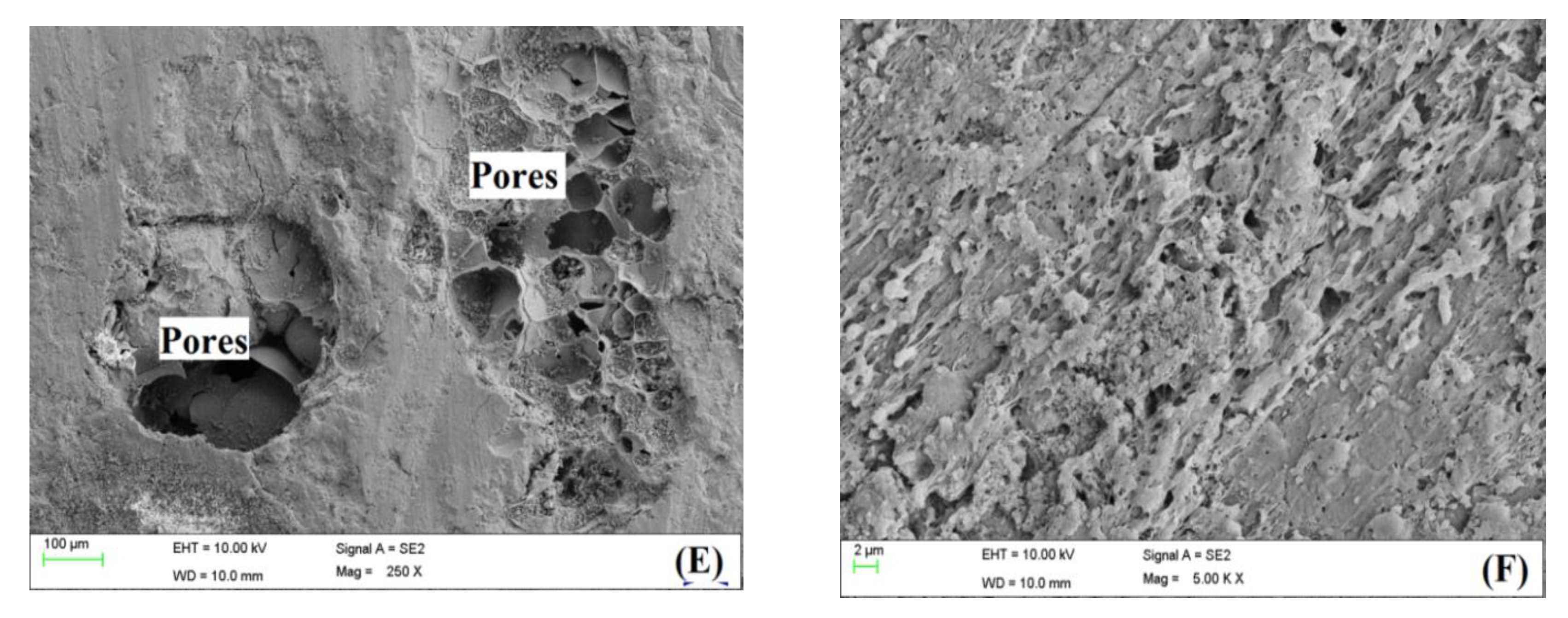
Field Emission Scanning Electron Microscopy (FESEM) examinations were carried out to evaluate the micro-structural properties of tested samples. FESEM images showed the formation of C-S-H in LWC. Figure 1 shows C-S-H gel formation and chemical distribution in the optimum mix (1:0.5:2.5). From the Energy Dispersive X-ray Spectroscopy (EDS) map, calcium and silicate content growth could be visualized in the lightweight concrete. The formation of calcium and silicate in LWC is shown in Figure 2A,B respectively. The initiation and development of the crack in LWC aredemonstrated in SEM analysis, and the crack is developed around LWA (Figure 2C,D). It is revealed that pores are smaller, and the connectivity between them is low (Figure 2E,F). The images of SEM showed that calcium-silicate-hydrate formation was at a higher level, contributing to the enhancement of strength properties. Therefore, from the study, the mechanical strength is the maximum for this particular combination compared to others.

2.2. Steel

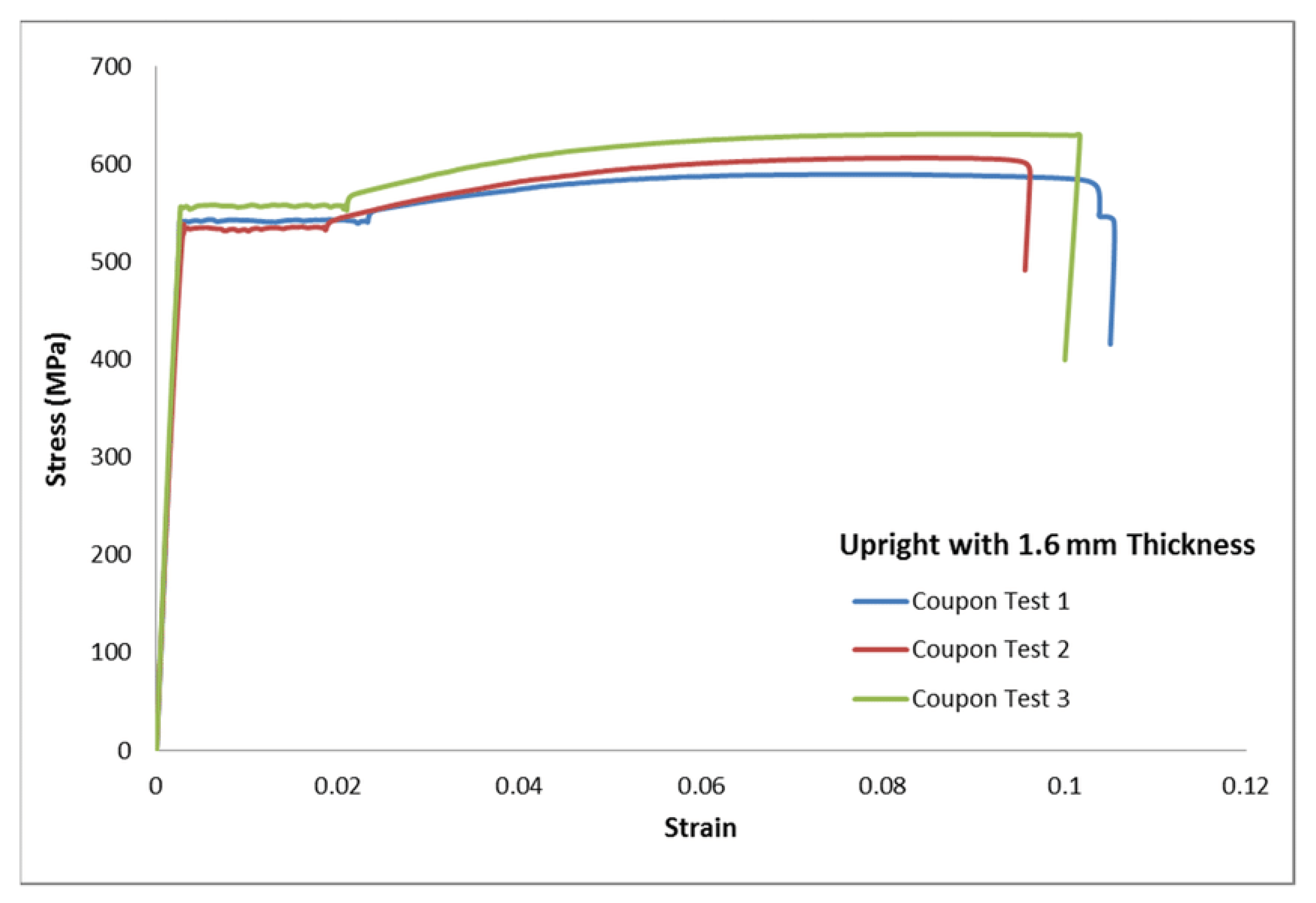
Cold-Form Steel (CFS) channel sections were used in the present investigation. The load-carrying capacity of CFS could be increased, resulting in more effective and cost-effective structural systems [37,38]. Four samples of CFS plates were tested using a tensile coupon according to ASTM E 8 [31]. Figure 3 displays the stress-strain curves from the tensile testing. Moreover, the self-tapping screw had a 640 MPa yield strength. Table 1 shows the results of the material testing.

Test Specimen

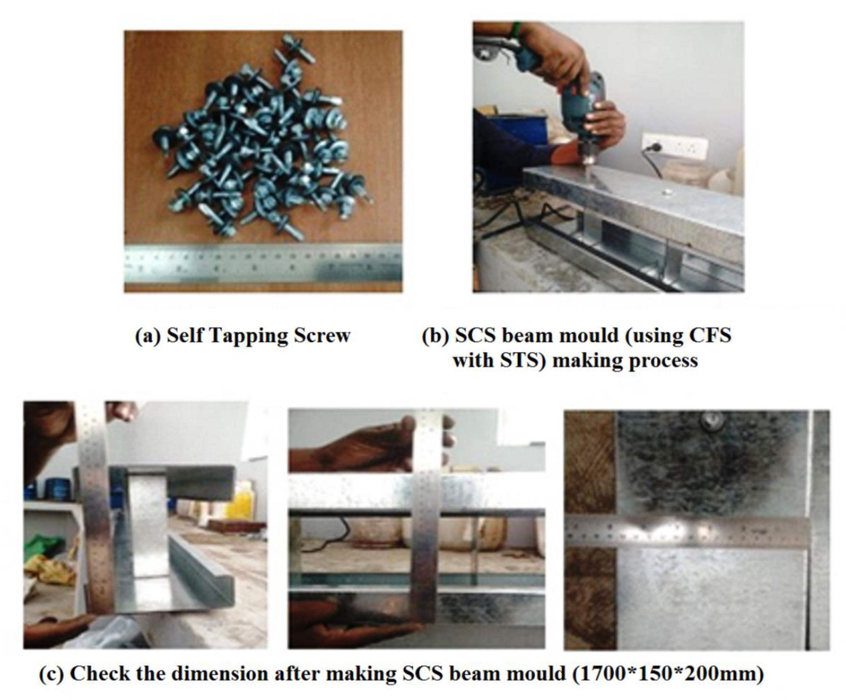
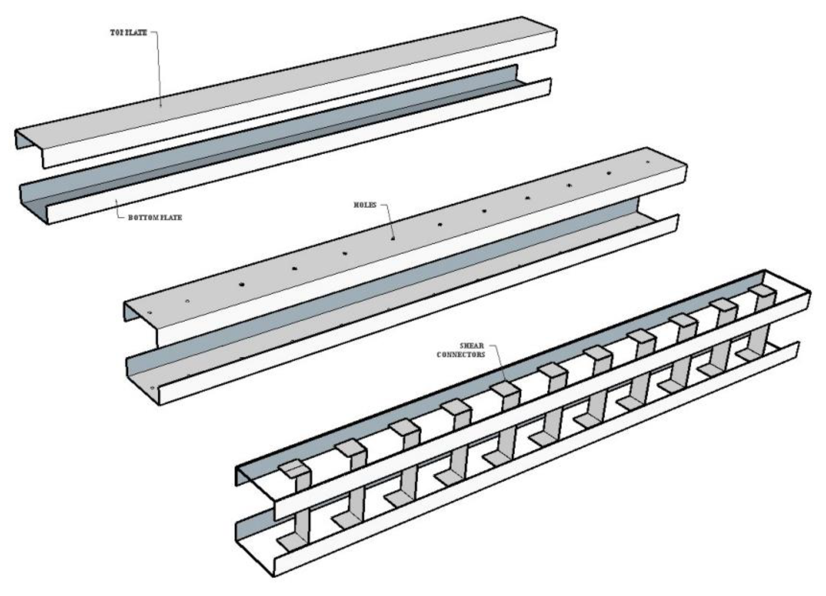
Figure 4 shows the fabrication of SCS sandwich beams with STS connectors. On the top and the bottom steel plates, the holes were first cut. Figure 4a displays the self-tapping screw. After positioning of ECs between the top and the bottom plates (see Figure 4b), the self-tapping screw was inserted via the holes in the steel plates. The specimen was then made to confirm the dimensions of the SCS beam (see Figure 4c). Figure 5 shows the step-by-step procedure of the SCS sandwich beam fabrication process. Concrete was cast into the skeleton of SCS sandwich beams. After the concrete had cured for 28 days, the specimens were ready. The geometric information for each specimen is listed in Table 2.
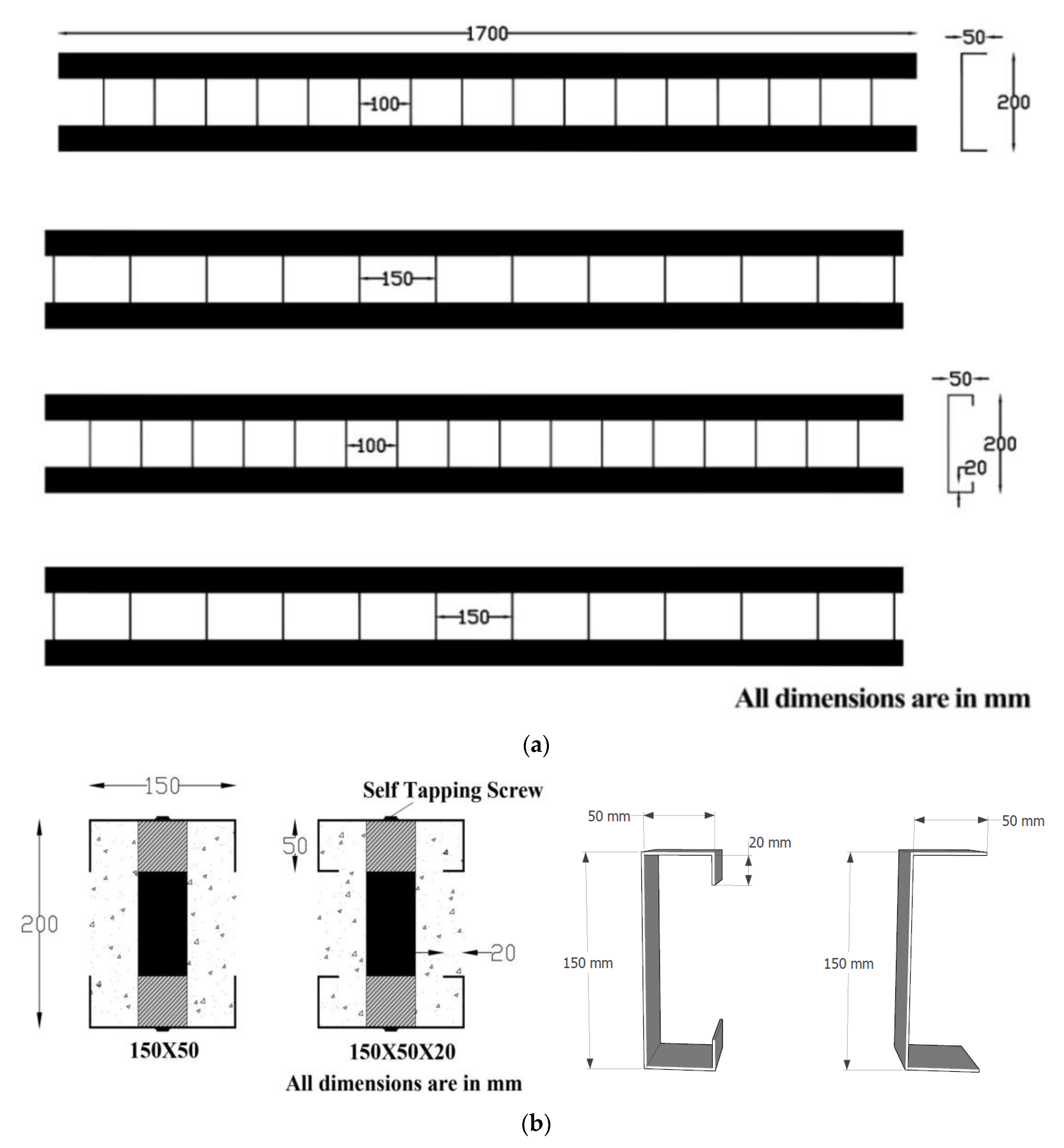
The specimen details of SCS sandwich beams are shown in Figure 6. All four beams had dimensions of 150 mm in width and 1700 mm in length. All the test specimens had connectors that were 6.25 mm in diameter, 1.6 mm thick100 and 150 mm apart. The connectors had self-tapping screws with hexagonal heads and embossed washers.

2.3. Test Setup and Testing Procedure

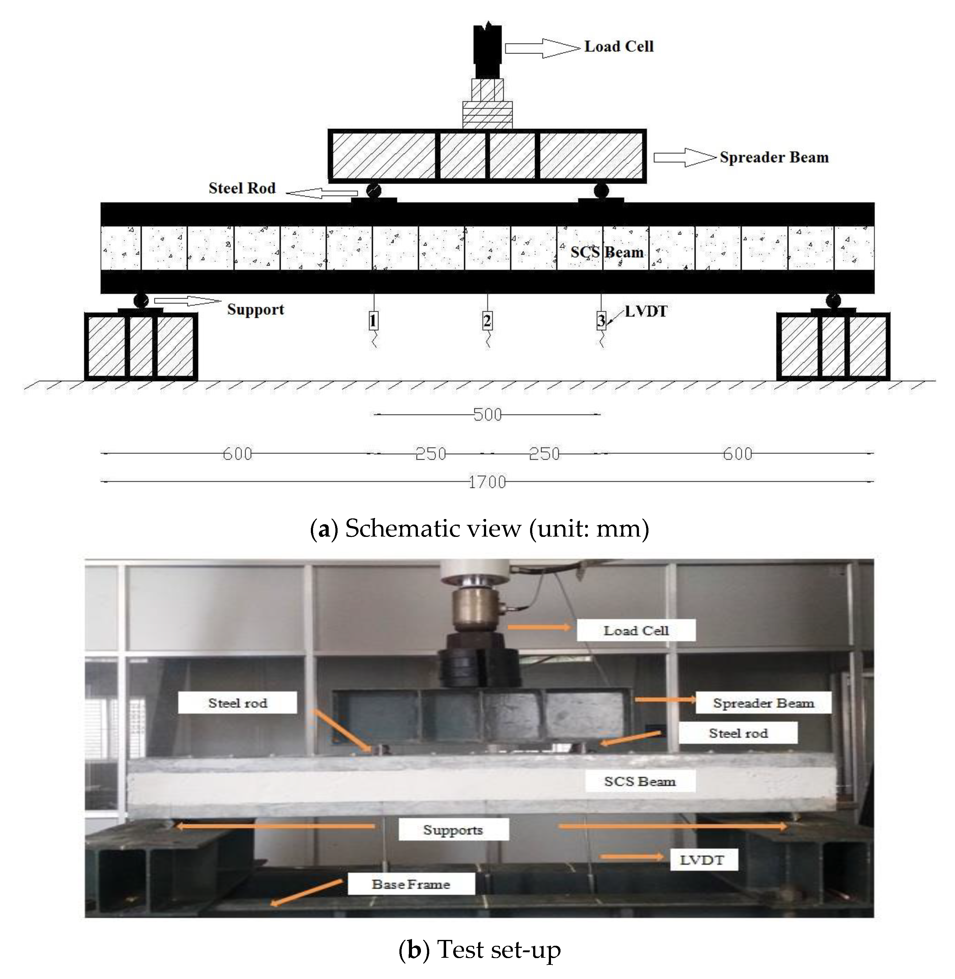
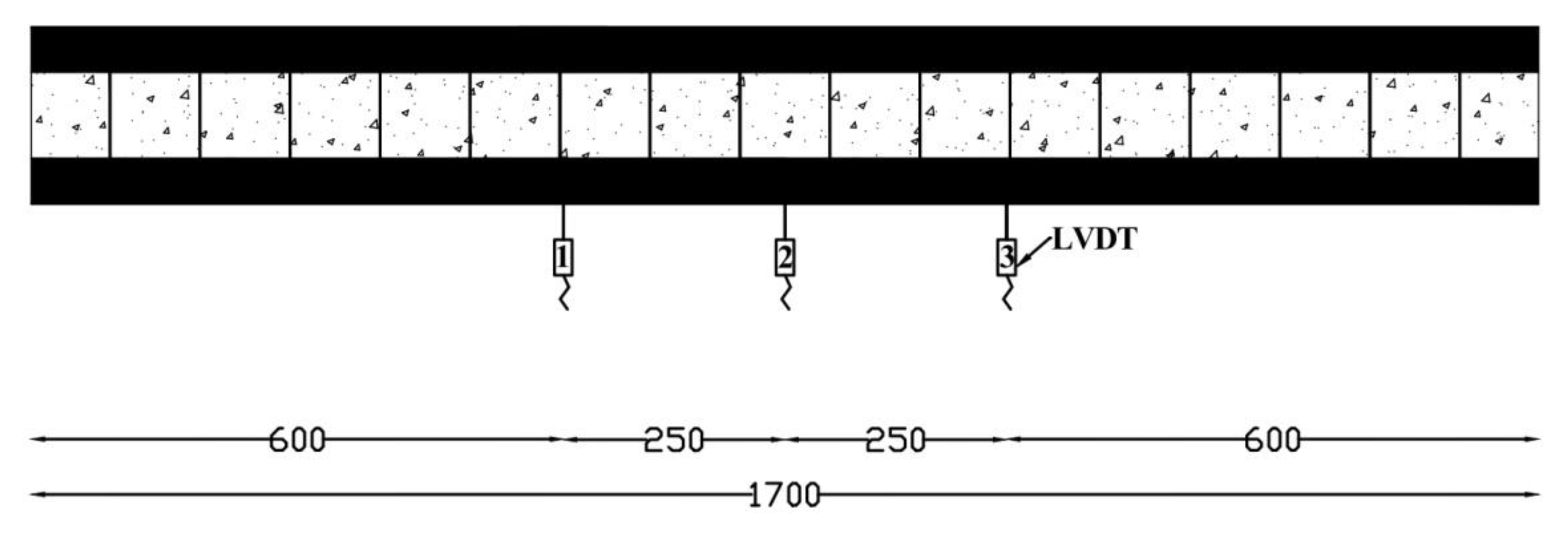
Figure 7 depicts the supports and the test configurations. Over a span of 1700 mm, SCS sandwich beams are considered simply supported. The beam was secured with two supports. Both fixed, and roller supports were provided. Similarly, two sides of those supports were attached to the beam at a distance of 100 mm. Transducers with linear variable displacement (LVDTs) were used to record vertical displacement time histories. As illustrated in Figure 8, the location of the LVDT is 600 mm from the beam faces and the middle of the beam. Using a data logger, the load-carrying capacity and displacements were recorded.
Based on the action of monotonic load, every specimen was investigated. The load is applied 250 mm from the midpoint of the beam. Table 3 shows the test results.

2.4. Analysis of SCS Sandwich Beams Damage

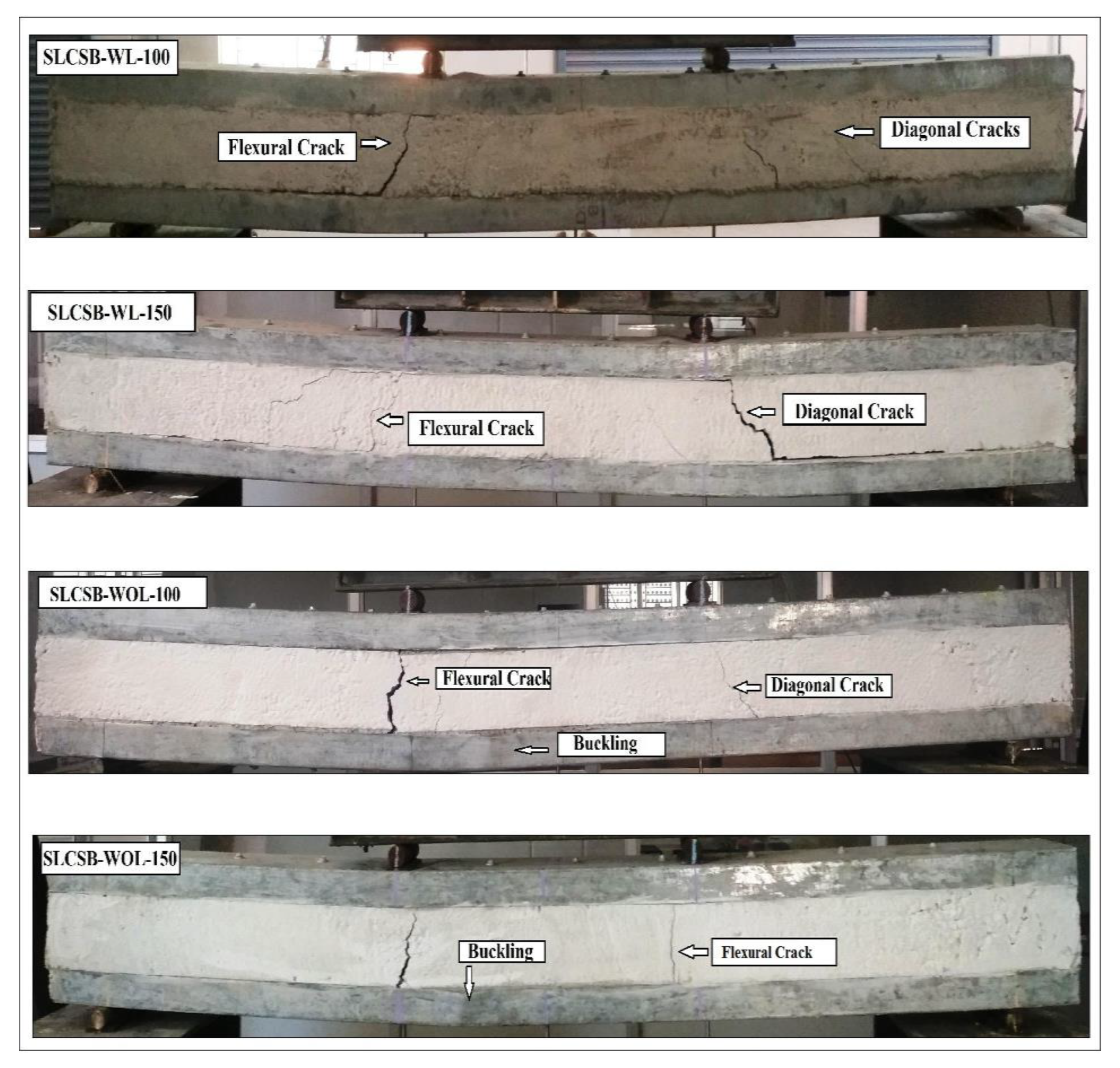
The loaded and damaged SCS sandwich beam depicted in Figure 9 exhibits three primary failure modes: bending, shearing, and cracking of the steel plates on the bottom. The specimen labeled SLCSB-WOL-150 has been identified as having experienced failure. Diagonal cracks indicative of flexure-shear failure were observed in specimens SLCSB-WL100, SLCSB-WL150, and SLCSB-WOL-100. In the case of the steel beams SLCSB-WOL-100 and SLCSB-WOL-150, bending occurred at the bottom flange when subjected to the applied load. Since the particular bottom steel was buckled, the beams without the lipped portion were easily destroyed while supporting the load. Lipped beams exhibited better buckling behaviour than without-lipped beams. While conserving the structural integrity of the SCS sandwich beam, shear connectors were employed to avoid the separation of the upper and lower steel plates.
Local indentation is low compared to global strain for all steel-concrete-steel composite beams analyzed. The steel-concrete-steel composite beams performance was significantly impacted by the change in impact position. Following the impact testing, as seen in Figure 10, the analysis of the camera-captured images was carried out in the case of the sandwich beam SCSB-WL-100 & 150, where the point of contact was between mid-span and support, diagonal shear cracks developed after developing the flexural cracks (Figure 10). It was carried out by relocating the impact position close to the support, which increased the impact-induced shear force.
Diagonal cracks appeared in the concrete core due to the beams’ substantial longitudinal and transverse shear pressures, impact bending forces, and shear stresses at off-center sites. All beams with bending shear failure mode showed the same performance. SCS sandwich beams SCSB-WL-100 and SCSB-concrete WL-150’s cores exhibit growing diagonal shear cracks. SCS sandwich beams are significantly more resistant because of their thicker concrete cores. A thick steel plate also contributes to SCS sandwich beams impact resistance. The flexural cracks start at the bottom of the concrete core. According to Figure 10, the fracture of the bolted joint causes the lower steel plate beneath the point of impact to rupture, with the bending fracture then commencing to spread to the higher steel plate. Similar to the top steel plate, which failed after the test owing to twisting brought on by a high buildup of tensile tension. The bending strength of the SCSB-WL-100 and SCSB-WL-150 beams was enhanced. Investigations were also conducted on the strength and failure mechanisms of steel-concrete-steel composite beams affected by shear connector spacing and the presence or absence of a top-down steel plate’s steel lip.

Load—Deflection History

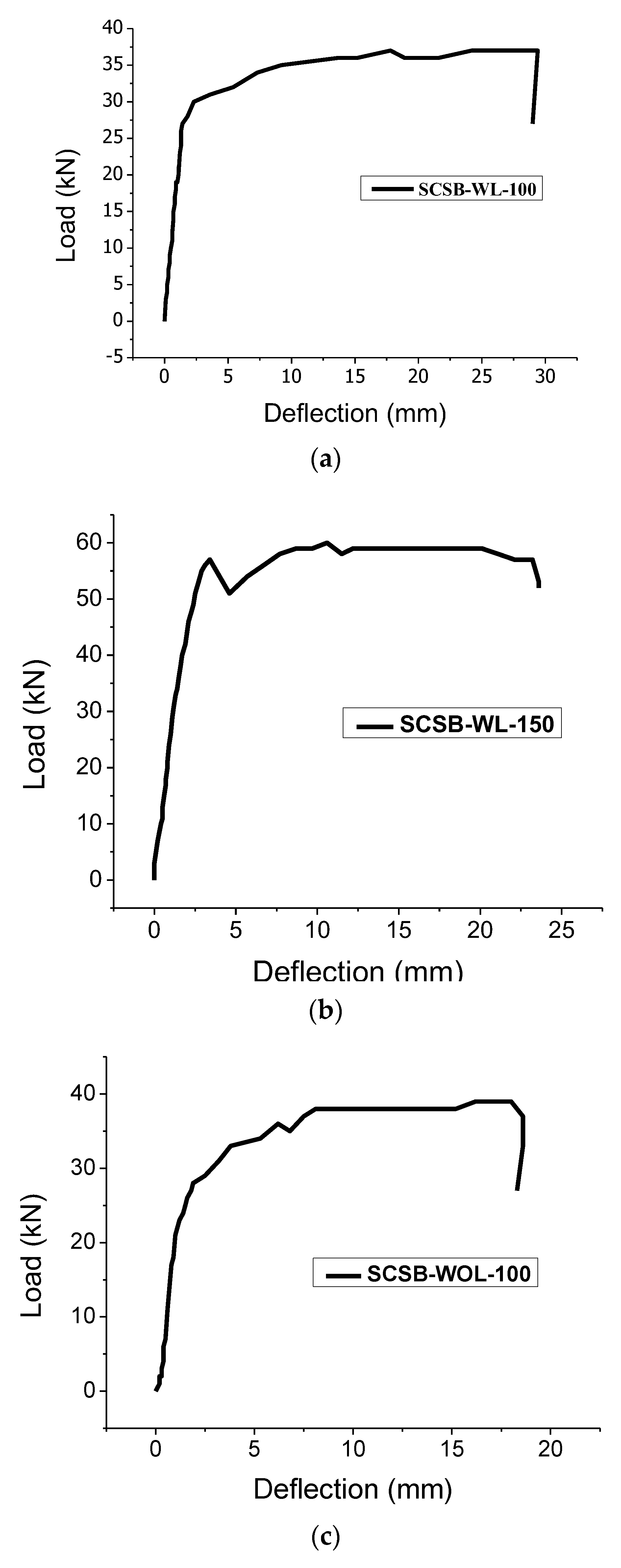
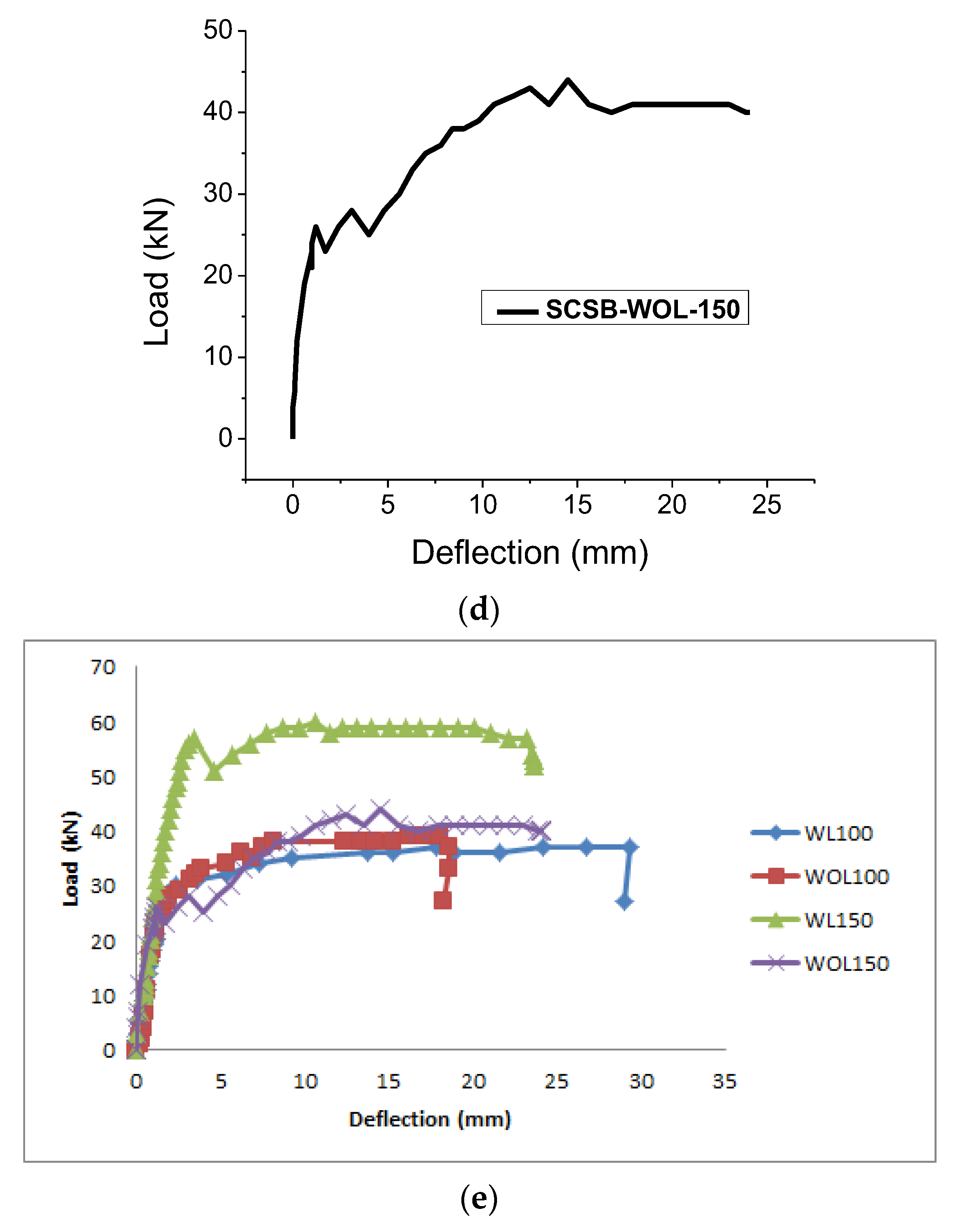
One of the three LVDTs depicted in Figure 8 was installed below the load cell. Therefore LVDT Numbers 1 and 3 were fixed from 250 mm at LVDT Number 2 on both sides. The deflection-load histories of four specimens, recorded by LVDT below the point of contact, are shown in Figure 11. The effects on deflection under various load factors are shown in Figure 11. Figure 11a illustrates the beam with the highest deflection among the four beams. The SCSB-WL-150 beam (Figure 11b) demonstrates the impact of greater load-bending history on the beam due to the thick concrete core. The permanent displacement acquired by the beams is SCSB-WOL-150, and the highest displacement is attained by SCSB, represented in Table 4. It is observed from Figure 9 that the steel plate has increased both the stiffness and resistivity of the steel-concrete-steel composite beams. Maximum displacements for the SCSB-WL-100 and SCSB-WOL-150 (Figure 11a,d) were reduced from 18.6 mm for the SCSB-WOL-100 to 29.40 mm and 24.10 mm, respectively.
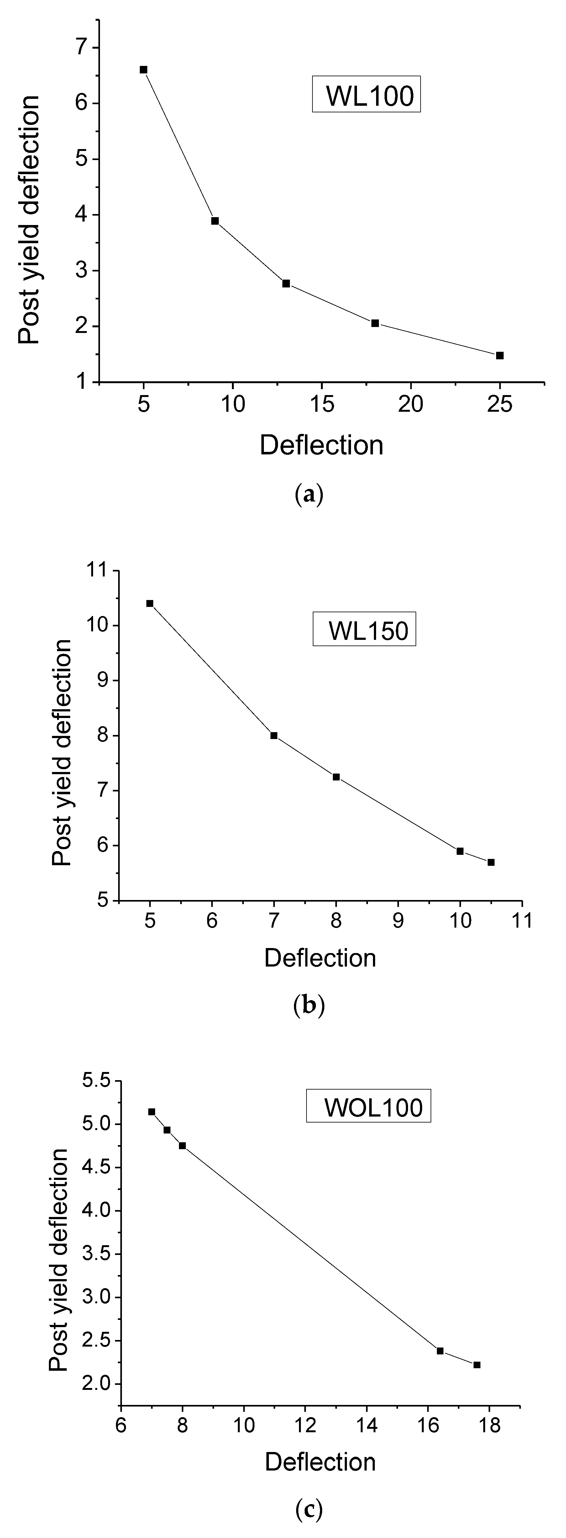
The post-yield deflection histories of four specimens are shown in Figure 12. The post-yield deflection was drawn from the stress-strain curve of the SCS beams. SCSB-WL-150 beam (Figure 12b) illustrates the maximum post-yield deflection of the beam. Figure 12a,c,d show the post-yield deflection that was low compared to SCSB-WL-150.

3. Theoretical Analysis

3.1. Flexural Behaviour

For the calculation of the SCS sandwich composite beams flexural resistance, the following assumptions were made; (1) The plane section remains plane; (2) the contribution of the concrete’s tensile strength is disregarded; and (3) the concrete is capable of developing a full plastic rectangular stress block [41,42]. Based on a cross-sectional plasticity investigation, the plastic stress distribution of SCS is depicted in Figure 13.
The following formula can be used to determine concrete’s compressive strength:
Ncc = η fck y b/γmc
where, b is the beam width; x is the neutral axis depth; η = 1.0 (for fck ≤ 50 Mpa) and =1.0 − (fck − 50)/200 (for 50 (for fck ≤ 90 Mpa); fck is the cube strength of the concrete; γmc is the partial safety factor for the concrete;
x = (Ncs − Nts)/(η fck by/γmc)
The shear strength of the connection or the steel plate’s yield strength under compression or tension of the concrete regulates the maximum force produced in the steel plate.
Ncs = min (nc Ps, fyAscmo)
where nc is the number of shear connectors. Ps is the shear connector strength. The surface steel’s yield strength is fy. The steel skin’s Asc region has to be crushed. The partial safety factor is called γmo.
The tensile force of a drawn steel plate can also be estimated using the same methodology.
Nts = min (nt Ps, fyAstmo)
where nt is the number of shear connectors in tension and attached to the skin. The region of the steel shell where each tension is applied is designated as Ast.
The flexural resistance of the composite sandwich panels is given below,
M u d = N t s   ( h c y + t s 2 ) + N c s ( y + t c 2 ) + N c c ( y x 2 )
where tc denotes the compression steel plate’s thickness. The thickness of the sheet under tension is known as ts. y = 0.8 (for fck ≤ 50 Mpa) and =0.8 − (fck − 50)/400 (for 50 (for fck ≤ 90 Mpa).

3.2. Shear Behavior

A composite sandwich beam’s lateral shear resistance depends on the shear strength of the concrete core and the shear strength of its connections. The following formula is given for SCS panels’ shear strength:
Vud = Vcd + Vsd
where Vcd is the design shear strength of the concrete. Vsd is the design shear resistance provided by the shear connector. Vcd and Vsd can be calculated as
V cd = C d k   η 1 ( 100   ρ 1   f ck )   1 / 3   b   ( h c + t c   E s E c )
Vsd = n0 T
where Cd = 0.18/γc for lightweight concrete; k = 1 + ( 200 h c ) ≤ 2.0; hc is the height of the concrete core in mm; η1 = 0.40 + 0.60 u/2200 is the tensile strength reduction coefficient; ρ1 = ts/[hc + (ts + tc)/2] ≤ 0.02; u = density of lightweight concrete in kg/m2; n0 is the number of shear connectors in the panel; T is the design tensile strength resistance of the shear connector embedded in the concrete

3.3. Combination of Bending Moment and Shear Force Resistance

According to Roberts et al. [46], the following is the design resistance for combined bending and shear.
( V u / V ud ) 2 + ( M u / M ud ) 2 1.0
where Vud and Mud stand for the beam section’s shear and bending strengths, respectively. The shearing forces and bending moments acting on the beam’s cross-section are Vu and Mu, respectively. Sandwich composite beams are tested for load-bearing capacity using the strength index R.

3.4. Ductility and Energy Dissipation

Testing specimen ductility is accomplished using energy dissipation and displacement ductility calculations. Only two elements affect the structural component’s ductile behaviour: the energy lost during the post-yield response and loading (Figure 14). Ductility (µ) is the ability to deform beyond the point of yield without experiencing a considerable loss of strength. The ductility factor is the product of the ultimate strain (Δu) and yield strain (Δy) in Equation (10).
µ = Δ u Δ y
For evaluating a component’s post-yield reaction, its energy dissipation capability is another essential characteristic. A load-deflection curve calculates energy loss based on a region covered by the curve. Table 4 shows the energy dissipation and measured ductility coefficients.
The contribution of shear connections and lightweight concrete to increase ductility could be seen clearly in the behavior of the “WL100” beam, and significantly, the “WL150” beam contributed higher energy dissipation capacity compared to the other specimens in the behavior of energy dissipation. The shear connectors and the location of their spacing determined how ductility was improved. Moreover, the shear connector spacing varied from beam to beam. Regarding the spacing of the shear connectors that were fixed in the composite beam, there was also an increase in energy dissipation. The “WL100” specimen exhibited an enhanced ductility behavior, and the shear connector spacing was smaller than the conventional composite beams. The “WL150” specimen showed better energy dissipation. It should be emphasized that the case specified included lips.
Regarding the SCS composite beam’s ductility factor and energy dissipation, the specimen “WOL150” performed poorly. The post-yield response affected the ductility more than the strength enhancement. The ductility of the specimen with shear connectors and lightweight concrete increased by two to three times. Whereas the ductility of the beam with shear connections fixed at the smallest possible distances was recorded as 400% higher than that of the other specimens. While the energy dissipation in specimens “WL100 and WL150” was not as large as it was in “WOL100 and WOL150,” the energy dissipation was observed as 70% and 50%, which were greater than “WOL100 and WOL150”.

3.5. Stiffness Degradation

The stiffness (k) property of the structural element is the measure of the resistance to deformation, given in Equation (11):
k = P Δ
where P—load, kN; Δ —deflection, mm.
The initial slope (tangent) of the load-deflection curve shows the initial stiffness of the specimens, whereas the slope of the line connecting the origin and failure point represents the secant stiffness of the specimens. The post-yield behaviour of the structural component is typically depicted by the difference between these two stiffnesses. The following equations are used in the proposed study to compute the stiffness degradation as a percentage of the yield stiffness [kdeg%] (12).
k d e g % = [ 1 k k y k y 100 ]
where k—stiffness (kN/mm); ky—yield stiffness (kN/mm).
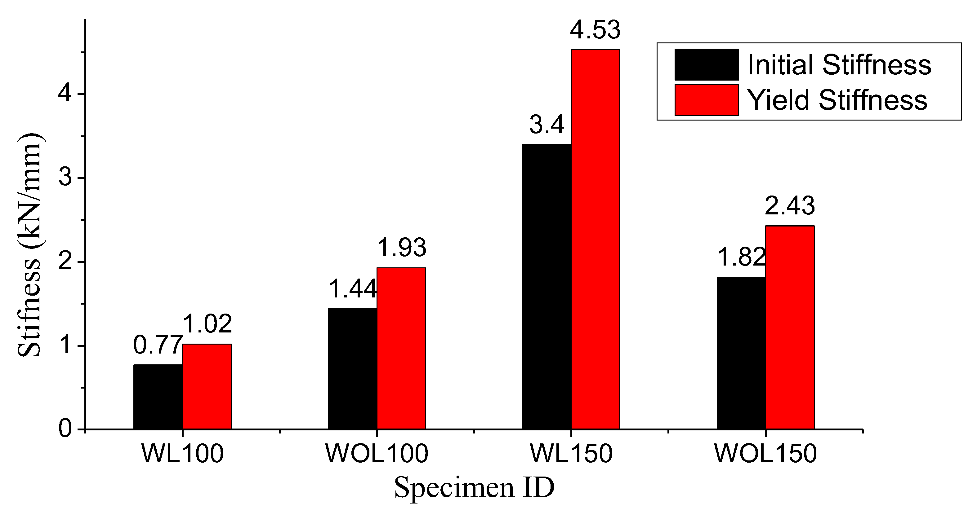
The load-deflection factor of beams provided the basis for the stiffness of the composite beam that was plotted. The rate of change in the strength and stiffness degradation across the post-elastic rotation was used to gauge the inelastic performances of structural elements. The ductile performance of the structural component was demonstrated by a low rate of degradation change and vice versa. The initial and yield stiffness of the composite beam are shown in Figure 15. Compared to the other beams, the stiffness of the beam (WL100) was relatively low. Considering the other beams, the WL150 beams had the maximum yield stiffness and were naturally and exceptionally rigid. While the stiffness values of WL100, WOL100, and WOL150 were only marginally different, the WL150 SCS beam exhibited improved stiffness behaviour. The behaviour of stiffness is mostly caused by the combination of shear connectors and lightweight concrete materials.

4. Discussion

In this experimental investigation, the structural behavior of Steel-Concrete-Steel (SCS) sandwich beams with Enhanced C-channel (EC) shear connectors in-filled with lightweight concrete (LWC) was examined. The obtained results can be compared to those obtained by other authors to assess the authors’ contribution and the novelty of their findings.
The authors utilized self-tapping screw connectors in their SCS sandwich beams, which prevented the separation of top and bottom steel plates during tensile loads. This connection type differs from other studies that might have employed different connectors, such as bolts or welds. The use of self-tapping screw connectors in this study offers practical advantages regarding ease of installation and increased load transfer capacity. The experimental results showed that EC shear connectors significantly increased the vertical shear strength of the SCS sandwich beams and improved the interfacial bonding between the steel faceplate and the LWC core. This finding is consistent with previous studies that have demonstrated the positive impact of shear connectors on shear resistance and load transfer in composite beams.
The stiffness of the SCS sandwich beams was not significantly affected by the spacing of the EC shear connectors. This indicates that the overall bending strength of the beams was not compromised, despite local buckling in the compression faceplates due to increased EC spacing. This finding contrasts with studies that may have shown a more pronounced effect of spacing on composite beams’ overall stiffness and bending capacity. The ductility and energy dissipation of the SCS sandwich beams were influenced by the EC shear connectors and the configuration of the cold-form steel sections. The beams with closely fixed EC shear connectors using self-tapping screws exhibited higher ductility and enhanced energy dissipation. This observation highlights the importance of the connection type and detailing in achieving desirable ductile behavior and improved energy absorption capacity in composite beams. The inclusion of lightweight concrete in the SCS beam specimens aimed to increase the shear capacity and load-carrying ability. The experimental results demonstrated that the SLCSB-WL150 beam exhibited improved structural performance and increased flexural strength compared to other configurations. This finding aligns with enhancing the overall capacity of composite beams through the use of lightweight concrete.
The exposure of steel to certain environmental conditions can affect its long-term durability. It is essential to consider the design and construction measures employed to mitigate such risks. The use of LWC, with appropriate mix ratios and additives like ceraplast 300 super-plasticizer and silica fume, can enhance the durability of the concrete. These additives help improve lightweight concrete’s mechanical properties and resistance, reducing permeability and increasing its resistance to environmental factors. Furthermore, the selection of Cold Form Steel (CFS) for the top and bottom face plates, along with self-tapping screws to secure the EC shear connectors, indicates the consideration of corrosion resistance and practicality in the field. Cold-formed steel is known for its durability and corrosion-resistant properties, making it a suitable choice for composite beam construction.

5. Conclusions

An experimental investigation has been conducted to determine the structural behavior of SCS sandwich beams with ECs shear connectors in-filled with lightweight concrete. Based on the results of these studies, the following conclusions are drawn:
  • In SCS sandwich beams with self-tapping screw connectors, the top and bottom steel plates are prevented from separating during tensile loads by self-tapping screw connectors. Self-tapping screw connection sandwich beams with SCS experienced three different types of failure. The lower steel plate failed due to bending, bending shear, and failure.
  • Composite beams with enhanced C-channel shear connectors were tested. According to the test results, the EC shear connector can increase the vertical shear strength of the beam as well as the interfacial bonding of the steel faceplate and the inner core. However, the load-deflection and post-yield deflection of the SCSB-WL-150 were higher than the other SCS beams. That was due to the spacing of the shear connectors, which was more sufficient to carry the ultimate loads from the SCS beam.
  • In addition, lightweight concrete (LWC)-filled sandwich composite beams were tested. The beam test was utilised to examine the ductility of various cold-form steel section patterns and ECs shear connector spacings. According to the test results, the sandwich beam with ECs shear connectors (SCSB-WL-150) has less ductility than SCSB-WL-100. The reason was that the ductility behavior was more due to the ECs shear connectors, which were closely fixed using a self-tapping screw connection. Compared to the beams un-lipped section, the ductility behavior of the lipped segment was enhanced. The energy dissipation of the SCS sandwich beam (SCSB-WL-150) was more than the other.
  • The stiffness of SLCSB was not significantly affected by the spacing of the ECs. Although the local buckling of compression faceplates was caused by the increasing EC spacing, it did not affect the SLCSB-ECs overall bending strength because of the increased spacing from 100 to 150 mm.
  • As beam strength and shear connector spacing increased, the load-deformation behavior of SCS-ECs beam specimens of WL150 improved drastically. The load and the deformation capacity of SCS beam specimens were enhanced by around 2–2.5 times compared to the other beam specimens. According to the test results, SLCSB-WL150 could successfully increase the beam specimen flexure and shear capability.
  • The main focus of the proposed study was that the application of lightweight concrete in SCS beam specimens increased the beam’s shear capacity and load-carrying ability. The test results indicate that the SLCSB-WL150 beam has improved structural performance and increased flexural strength.

Author Contributions

A.A. visualization, Experimental Investigation, validation, resources, data curation, original draft preparation. B.S.: Conceptualization, methodology, supervision & project administration. G.R.: Formal analysis, writing—review and editing. All authors have read and agreed to the published version of the manuscript.

Funding

This research received no external funding.

Data Availability Statement

Data used in this study is available on request.

Conflicts of Interest

These authors declare no conflict of interest.

References

  1. Sohel, K.M.A.; Liew, J.R.; Yan, J.B.; Zhang, M.H.; Chia, K.S. Behavior of steel–Concrete–steel sandwich structures with lightweight cement composite and novel shear connectors. Compos. Struct. 2012, 74, 3500–3509. [Google Scholar] [CrossRef]
  2. Oduyemi, T.O.S.; Wright, H.D. An experimental investigation into the behaviour of double skin sandwich beams. J. Constr. Steel Res. 1989, 14, 197–220. [Google Scholar] [CrossRef]
  3. Liew, J.Y.R.; Sohel, K.M.A. Lightweight steel–concrete–steel sandwich system with J-hook connectors. Eng. Struct. 2009, 31, 1166–1178. [Google Scholar] [CrossRef]
  4. Liew, J.Y.R.; Sohel, K.M.A.; Koh, C.G. Impact tests on steel–concrete–steel sandwich beams with lightweight concrete core. Eng. Struct. 2009, 31, 2045–2059. [Google Scholar] [CrossRef]
  5. Varma, A.H.; Zhang, K.; Chi, H.; Booth, P.; Baker, T. In-Plane Shear Behavior of SC Composite Walls: Theory vs. Experiment. In Proceedings of the Transactions, SMiRT 21, New Delhi, India, 6–11 November 2011. Div-VI: Paper ID# 764. [Google Scholar]
  6. Mizuno, J.; Koshika, N.; Sawamoto, Y.; Niwa, N.; Yamashita, T.; Suzuki, A. Investigation on Impact Resistance of Steel Plate Reinforced Concrete Barriers Against Aircraft Impact. Part 1: Test Program and Results. In Proceedings of the 18th International Conference on Structural Mechanics in Reactor Technology (SMiRT 18), Beijing, China, 7–12 August 2005. SMiRT18-J05. [Google Scholar]
  7. Marshall, P.W.; Palmer, A.C.; Wang, T.Y.; Thein, M.K.W. Bond Enhancement for Sandwich Shell Ice Wall. In Proceedings of the International Conference and Exhibition on Performance of Ships and Structures in Ice, Anchorage, AK, USA, 20–23 September 2010. Paper No. 172. [Google Scholar]
  8. Remennikov, A.; Gan, E.C.J.; Ngo, T.; Netherton, M.D. The development and ballistic performance of protective steel-concrete composite barriers against hypervelocity impacts by explosively formed projectiles. Compos. Struct. 2019, 207, 625–644. [Google Scholar] [CrossRef]
  9. Roberts, T.M.; Edwards, D.N.; Narayanan, R. Testing and analysis of steel-concrete-steel sandwich beams. J. Constr. Steel Res. 1996, 38, 257–279. [Google Scholar] [CrossRef]
  10. Yan, J.B.; Liew, J.Y.R.; Zhang, M.H.; Sohel, K.M.A. Experimental and analytical study on ultimate strength behavior of steel-concrete-steel sandwich composite beam structures. Mater. Struct. 2015, 48, 1523–1544. [Google Scholar] [CrossRef]
  11. Yan, C.; Wang, Y.; Zhai, X. Low velocity impact performance of curved steel-concrete- steel sandwich shells with bolt connectors. Thin-Walled Struct. 2020, 150, 106672. [Google Scholar] [CrossRef]
  12. Xie, M.; Foundoukos, N.; Chapman, J.C. Static tests on steel-concrete-steel sandwich beams. J. Constr. Steel Res. 2007, 63, 735–750. [Google Scholar] [CrossRef]
  13. Leekitwattana, M.; Boyd, S.W.; Shenoi, R.A. Evaluation of the transverse shear stiffness of a steel bi-directional corrugated-strip-core sandwich beam. J. Constr. Steel Res. 2011, 67, 248–254. [Google Scholar] [CrossRef]
  14. Leng, Y.B.; Song, X.B.; Chu, M.; Ge, H.H. Experimental study and theoretical analysis of resistance of steel-concrete-steel sandwich beams. J. Struct. Eng. 2015, 141, 1–11. [Google Scholar] [CrossRef]
  15. Yan, J.B.; Guan, H.; Wang, T. Steel-UHPC-steel sandwich composite beams with novel enhanced C-channel connectors: Tests and analysis. J. Constr. Steel Res. 2020, 170, 106077. [Google Scholar] [CrossRef]
  16. Yan, J.B.; Guan, H.N.; Wang, T. Finite element analysis for flexural behaviours of SCS sandwich beams with novel enhanced C-channel connectors. J. Build. Eng. 2020, 31, 101439. [Google Scholar] [CrossRef]
  17. Yan, J.B.; Wang, Z.; Wang, T. Shear and tensile behaviors of headed stud connectors in double skin composite shear wall. Steel Compos. Struct. 2018, 26, 759–769. [Google Scholar]
  18. Malek, N.; Machida, A.; Mutsuyoshi, H.; Makabe, T. Steel–Concrete sandwich members without shear reinforcement. Trans. Jpn. Concr. Inst. 1993, 15, 1279–1284. [Google Scholar]
  19. Yousefi, M.; Ghalehnovi, M. Push-out test on the one end welded corrugated-strip connectors in steel-concrete-steel sandwich structure. Steel Compos. Struct. 2017, 24, 23–35. [Google Scholar] [CrossRef]
  20. Yousefi, M.; Ghalehnovi, M. Finite element model for interlayer behavior of double skin steel-concrete-steel sandwich structure with corrugated-strip shear connectors. Steel Compos. Struct. 2018, 27, 123–133. [Google Scholar]
  21. Yan, J.B.; Liew, J.Y.R.; Qian, X.; Wang, J.Y. Ultimate strength behavior of curved steel-concrete-steel sandwich composite beams. J. Constr. Steel Res. 2015, 115, 316–328. [Google Scholar] [CrossRef]
  22. Yan, C.; Wang, Y.; Zhai, X.; Meng, L.; Zhou, H. Experimental study on curved steelconcrete-steel sandwich shells under concentrated load by a hemi-spherical head. Thin-Walled Struct. 2019, 137, 117–128. [Google Scholar] [CrossRef]
  23. Yan, C.; Wang, Y.; Zhai, X.; Meng, L. Strength assessment of curved steel-concretesteel sandwich shells with bolt connectors under concentrated load. Eng. Struct. 2020, 212, 110465. [Google Scholar] [CrossRef]
  24. Sjaarda, M.; West, J.S.; Scott, W. Performance of embedded bolt shear connectors. Struct. Eng. Int. 2020, 30, 421–429. [Google Scholar] [CrossRef]
  25. Pavlović, M.; Marković, Z.; Veljković, M.; Buđevac, D. Bolted shear connectors vs. headed studsbehaviour in push-out tests. J. Constr. Steel Res. 2013, 88, 134–149. [Google Scholar] [CrossRef]
  26. Lin, Y.; Yan, J.; Wang, Z.; Fan, F.; Yang, Y.; Yu, Z. Failure mechanism and failure patterns of SCS composite beams with steel-fiber-reinforced UHPC. Eng. Struct. 2020, 211, 110471. [Google Scholar] [CrossRef]
  27. Lin, Y.; Yan, J.; Cao, Z.; Zeng, X.; Fan, F.; Zou, C. Ultimate strength behaviour of SUHPC-S and SCS sandwich beams under shear loads. J. Constr. Steel Res. 2018, 149, 195–206. [Google Scholar] [CrossRef]
  28. Yan, J.B.; Hu, H.; Wang, T. Flexural behaviours of steel-UHPC-steel sandwich beams with J-hook connectors. J. Constr. Steel Res. 2020, 169, 106014. [Google Scholar] [CrossRef]
  29. Remennikov, A.M.; Kong, S.Y.; Uy, B. The response of axially restrained noncomposite steel-concrete-steel sandwich panels due to large impact loading. Eng. Struct. 2013, 49, 806–818. [Google Scholar] [CrossRef] [Green Version]
  30. Wang, Y.; Liew, J.Y.R.; Lee, S.C. Experimental and numerical studies of noncomposite steel-concrete-steel sandwich panels under impulsive loading. Mater. Des. 2015, 81, 104–112. [Google Scholar] [CrossRef]
  31. Wang, Y.; Liew, J.Y.R.; Lee, S.C. Theoretical models for axially restrained steelconcrete- steel sandwich panels under blast loading. Int. J. Impact Eng. 2015, 76, 221–231. [Google Scholar] [CrossRef]
  32. Guo, Q.; Zhao, W. Displacement response analysis of SC composite panels subjected to impact loadings. Int. J. Impact Eng. 2019, 131, 272–281. [Google Scholar] [CrossRef]
  33. Yan, J.B.; JYR, L.; Zhang, M.H.; Wang, J.Y. Ultimate strength behaviour of steel-concretesteel sandwich composite structures, part 1: Experimental and analytical study. Steel Compos. Struct. 2014, 17, 907–927. [Google Scholar] [CrossRef]
  34. Wang, A.J.; Chung, K.F. Advanced finite element modelling of perforated composite beams with flexible shear connectors. Eng. Struct. 2008, 30, 2724–2738. [Google Scholar] [CrossRef]
  35. Yan, J.B.; JYR, L.; Zhang, M.H. Ultimate strength behaviour of steel-concrete-steel sandwich composite structures, part 2: Finite element analysis. Steel Compos. Struct. 2015, 18, 1001–1021. [Google Scholar] [CrossRef]
  36. Yan, J.B. Finite element analysis on finite element analysis on ultimate strength behaviourof steel-concrete-steel sandwich composite beam structures. Mater. Struct. 2015, 48, 1645–1667. [Google Scholar] [CrossRef]
  37. Wang, Y.; Sah, T.P.; Lu, J.; Zhai, X. Behaviour of steel-concrete-steel sandwich beams with bold connectors under off-center impact load. J. Constr. Steel Res. 2021, 186, 106889. [Google Scholar] [CrossRef]
  38. Lee, J.; Kim, S.-M.; Park, H.-S.; Woo, B.-H. Optimum design of cold-formed steel channel beams using micro Genetic Algorithm. Eng. Struct. 2005, 27, 17–24. [Google Scholar] [CrossRef]
  39. Lim, J.B.P.; Nethercot, D.A. Ultimate strength of bolted moment-connections between cold-formed steel members. Thin-Walled Struct. 2003, 41, 1019–1039. [Google Scholar] [CrossRef]
  40. Khatibi, S.H.; Arab, H.G.; Miri, M. The behavior of steel-concrete-steel sandwich composite beams with box-profile shear connectors: Experimental and numerical. Structures 2023, 54, 644–656. [Google Scholar] [CrossRef]
  41. Liu, X.; Tang, L.; Jing, Y.; Xiang, J.; Tian, X.; Liu, W.; Huang, Y.; Zhang, G.; Zhao, W.; Yang, G. Behaviour of continuous steel–concrete composite beams strengthened with CFRP sheets at hogging-moment region. Compos. Struct. 2022, 291, 115695. [Google Scholar] [CrossRef]
  42. Su, C.; Wang, X.; Ding, L.; Wu, Z. Seismic degradation behavior of steel-FRP composite bar reinforced concrete beams in marine environment based on experimental and numerical investigation. Compos. Struct. 2023, 313, 116949. [Google Scholar] [CrossRef]
  43. Shakarami, M.; Zeynalian, M.; Ataei, A. Numerical study of the behavior of friction-grip bolted shear connectors in composite beams with cold-formed steel sections. Thin-Walled Struct. 2023, 184, 110539. [Google Scholar] [CrossRef]
  44. Dar, M.A.; Subramanain, N.; Ghowsi, A.F.; Anbarasu, M.; Hajirasouliha, I.; Haris, S.; Dar, A.R. Intermittently stiffened cold-formed steel GFRP composite lightweight built-up beams: Experimental investigation and performance assessment. Thin-Walled Struct. 2023, 185, 110630. [Google Scholar] [CrossRef]
  45. Ungureanu, V.; Both, I.; Burca, M.; Radu, B.; Neagu, C.; Dubina, D. Experimental and numerical investigations on built-up cold-formed steel beams using resistance spot welding. Thin-Walled Struct. 2021, 161, 107456. [Google Scholar] [CrossRef]
  46. Xiong, G.; Li, W.; Wang, X.; Liu, J.; Bai, Y.; Chen, Y.F. Flexural behavior of prefabricated high-strength steel-concrete composite beams with steel block connectors. J. Constr. Steel Res. 2022, 197, 107507. [Google Scholar] [CrossRef]
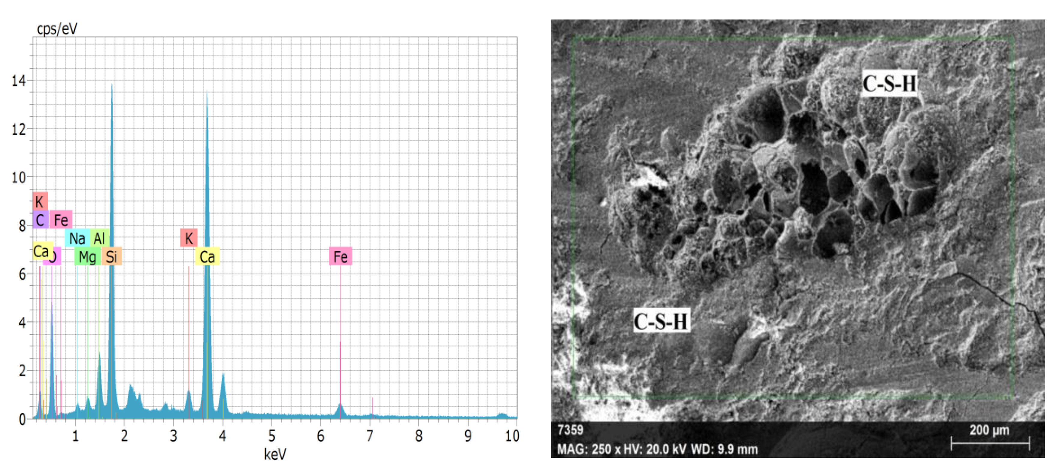
Figure 1. Microstructure of C-S-H formation for MN31 andEDS elemental analysis.
Buildings 13 01956 g001
Figure 2. Morphology of MN31 lightweight concrete after testing. (A) Calcium, (B) Silica, (C) Pumice stone, (D) Cracks, (E) and (F) Pores.
Buildings 13 01956 g002aBuildings 13 01956 g002b
Figure 3. Tensile stress-strain curve for CFS (1.6 mm) plate.
Buildings 13 01956 g003
Figure 4. Process of makingSCS beam mouldusing a self-tapping screw.
Buildings 13 01956 g004
Figure 5. Schematic view of SCS sandwich beam fabrication process.
Buildings 13 01956 g005
Figure 6. Sandwich beams with SCS connectors (a) front view, (b) cross-section, and schematic image.
Buildings 13 01956 g006
Figure 7. Setup of four-point bending test on SCS-ECs with LVDTand its Details.
Buildings 13 01956 g007
Figure 8. Layout of LVDT (Unit: mm).
Buildings 13 01956 g008
Figure 9. Damaged SCS sandwich beams.
Buildings 13 01956 g009
Figure 10. Photos of failure pattern at various time intervals during the load. Note: M—minutes.
Buildings 13 01956 g010
Figure 11. Load-Deflection history. (a) SCSB-WL-100, (b) SCSB-WL-150, (c) SCSB-WOL-100, (d) SCSB-WOL-150 and (e) Comparative Load−Deflection curve for different composite beam.
Buildings 13 01956 g011aBuildings 13 01956 g011b
Figure 12. History of post-yield deflection. (a) WL100, (b) WL150, (c) WOL100 and (d) WOL150.
Buildings 13 01956 g012aBuildings 13 01956 g012b
Figure 13. Stress distribution in SCS at ultimate bending moment.
Buildings 13 01956 g013
Figure 14. (a) Ductilitybehavior and (b)Energy dissipation behavior.
Buildings 13 01956 g014
Figure 15. Initial and Yield stiffness of the SCS beam.
Buildings 13 01956 g015
Table 1. Material properties.
Lightweight ConcreteCompressiveStrength of Concrete (MPa)Young’s Modulus for Concrete (GPa)Density of Concrete (kg/m3)
17.6536.741438.48
CFS platets (mm)Yield strength of steel (MPa)Young’s modulus for steel (GPa)
1.6310.92186.65
Self Tapping Screw (STS)Diameter (mm)yield strength of steel (MPa)Young’s modulus for steel (GPa)
6.25640210.00
Table 2. Specimen details.
Beam IDTypeThickness of Steel Plate
(mm)
Width of Beam
(mm)
Diameter of Bolt
(mm)
Depth of Concrete Core
(mm)
Spacing of Connectors
(mm)
SLCSB1WL1.61506.25196.8100
SLCSB2WL1.61506.25196.8150
SLCSB3WOL1.61506.25196.8100
SLCSB4WOL1.61506.25196.8150
Note: WL—with lipped, WOL—without lipped.
Table 3. Experimental results.
Beam IDTypeSC
(mm)
Fmax
(kN)
D0
(mm)
Dmax
(mm)
Dp
(mm)
SLCSB1WL100370.1029.49.2
SLCSB2WL150600.2023.618
SLCSB3WOL100390.2018.612.3
SLCSB4WOL150440.1024.118.9
Note: Sc = spacing of connectors, Fmax = maximum load, D0 = displacement of first peak value, Dmax = the maximum displacement, Dp = permanent displacement.
Table 4. Average test results of composite beam specimens.
Beam IDYield StageDuctility (µ)Energy Dissipation (kN-mm)Initial Stiffness (Ki)Yield Stiffness (Ky)
Py (kN)Δy (mm)
WL100372514.35790.320.771.02
WOL1003917.65.63474.241.441.93
WL1506010.511.310083.44.53
WOL15041.523.52.875281.822.43
Disclaimer/Publisher’s Note: The statements, opinions and data contained in all publications are solely those of the individual author(s) and contributor(s) and not of MDPI and/or the editor(s). MDPI and/or the editor(s) disclaim responsibility for any injury to people or property resulting from any ideas, methods, instructions or products referred to in the content.