Abstract
Stability calculation is the main objective during the analysis of domes. To investigate the effects of the initial defect, geometric nonlinearity, and material nonlinearity on the stability performance of different dome structures, 60 m numerical models were built and optimized by an iterative force-finding APDL program. Then, linear buckling analysis, geometric nonlinear stability analysis, geometric nonlinear stability analysis with initial defects, and dual nonlinear analysis with initial defects were discussed to compare the stability performance of ridge-beam cable domes (RCDs), suspen-domes, and conventional cable domes via finite element analysis. The results show that the buckling loads all follow the order of initial defect + dual nonlinear analysis < initial defect + geometric nonlinear analysis < geometric nonlinear analysis < linear buckling. The addition of ridge beams improves the overall stability and transforms the instability modes from local concave instability to overall torsional buckling. The ultimate load amplification coefficients of the RCD are close to those of the suspen-dome, while the vertical displacements of the RCD are more than those of the conventional cable dome, so the RCD has sufficient stiffness to reduce local displacement. Under 2–3 load combinations, internal ridge beams change from a tensile-bending state to a compressive-bending state, causing the entire instability of the RCD afterwards.
1. Introduction
Different from rigid frames [1], domes are a type of large-span spatial structure based on the idea of tensegrity [2]. This structure caters to the development trend of the space structure and is a commanding height with practical application value. Furthermore, it integrates new materials, new technologies, new processes, and high efficiency [3].
According to the roof form, dome structures are mainly divided into two types: flexible roofs composed of tensile membranes and rigid roofs composed of glass or steel plates. Due to architectural and structural requirements, the size of the grid between adjacent structural components of the conventional cable dome should be designed to be relatively large, which requires the roof system itself to have good spanning performance. Therefore, the main roofing materials for conventional cable dome structures are lightweight tensile membranes.
A tensile membrane [4] is a kind of flexible material with the characteristics of thin thickness, light transmission, and a negative Gaussian surface, but its thermal insulation performance and environmental pollution resistance are poor. In addition, the demand for functional diversity of buildings and the pollution of the external environment both make membrane materials an important factor limiting the wider application of cable domes.
Traditional rigid roofing materials [5], such as glass panels, color steel plates, and aluminum alloy panels, have been widely used in conventional structures. However, the spanning capacity of rigid roof slabs is small. Thus, it is necessary to add a secondary structure to support the roof and transfer the roof load to the main structure, which requires high demand for the spanning capacity of the secondary structure. For conventional cable domes, the secondary structure should be placed on the top of compression rods, not on flexible cables. Otherwise, relatively larger cable forces should be built to provide enough bearing capacity to support the upper heavy roofing system and reduce mid-span deflection, based on the premise of negligible bending stiffness of cables.
A suspen-dome [6] is a hybrid spatial structure that combines rigidity and flexibility. It consists of an upper single-layer reticulated shell and a lower cable–rod system [7] and thus exerts the characteristics of these two structures. On the one hand, the idea of a tensegrity system is introduced into the single-layer reticulated shell [8], which enlarges out-of-plane stiffness and improves the stable bearing capacity of the structure. On the other hand, the addition of an upper rigid reticulated shell greatly reduces the difficulty of construction and facilitates the installation of rigid roofs [9]. However, to enhance the local stability and integrity of the structure to bear compression and bending moments during the serviceability stages, rigid connections, such as fusion-through welding and welded spherical joints, are adopted on the single-layer reticulated shell. In this case, the member sizes of the upper single-layer reticulated shell are generally designed to be large, and the high-altitude assembly method is generally used to finish the installation of the suspen-dome, which requires a large number of brackets and high construction measures.
Currently, rigid-beam cable domes (RCDs) [10], using hinged ridge beams as the upper bearing members and building prestress in all the hinged beams, are receiving increasing attention. First, all the connecting nodes between the hinged ridge beams and adjacent cables or rods are hinged, which fulfils the requirements of retractable buildings and realizes the non-support integral tow-lifting construction [11] of the entire structure. Second, due to the addition of hinged ridge beams, an RCD has enough flexural rigidity to reduce local displacement and can be welded or drilled to connect purlins and other roofing auxiliary components. Therefore, RCD could support a heavy rigid roofing system. Third, compared with the upper grid of the suspen-dome, which bears compression forces and bending moments under static loads, the upper-beam grid bears both tension forces and bending moments in normal loading stages, which contributes to improving the overall stability of the overall structure and produces a relatively large stability capacity. Compared with conventional cable domes and suspend-domes, RCDs are an excellent improved form for steel dome structures. Pan [12] designed an experimental model of a Geiger-type RCD with a diameter of 6 m, verified the feasibility of the non-bracket construction method for RCD, and investigated the mechanical properties of RCD under static loading conditions. Ding [13] established refined finite element models for RCDs and compared the static response and vibration characteristics of RCDs, suspen-domes, and conventional cable domes afterwards. Zuo [14] conducted research on the mechanical properties and static simulations of Levy-type RCDs and proposed several feasible setting modes for the connecting joints of ridge beams. However, research on the stability characteristics of RCDs is lacking.
The stability of a structure refers to its ability to maintain its shape and position under external loads [15], which determines the reliability of the structure in normal use stages [1]. Wang et al. [16] presented a new framework for the stress analysis of three-dimensional (3D) composite (multi-layered) elastic materials using a meshless generalized finite difference method (GFDM), which could be used to perform stability analysis. By introducing the Bézier multistep method, Kabir and Aghdam [17] developed and implemented an accurate Bézier-based multistep method to find the nonlinear vibration and post-buckling configurations of Euler-Bernoulli composite beams reinforced with graphene nano-platelets. Bert and Malik [18] proposed an up-to-date account of the works in which the differential quadrature method has been employed for the analysis of laminated composite structures. More recently, Chen et al. [19] proposed a correction coefficient to diminish the discrepancy between the predicted and numerical results via FE analysis (FEA). For RCD, the upper ridge beam grid will greatly increase the local stiffness, and the pretension applied in the ridge beams will significantly improve the elastic deformation resistance, thus improving the stability of the overall structure. In this case, based on existing studies, the RCD is compared with a conventional cable dome and a suspen-dome in terms of stability characteristics through numerical simulations by ANSYS in this study.
2. Introduction of RCD
A ridge-beam cable dome (RCD) consists of ridge beams, oblique cables, ring cables, rods, mechanical hinges in the midpoints or ends of ridge beams, an outer compression ring, and an inner pulling ring, as shown in Figure 1. By replacing the flexible ridge cables of a conventional cable dome with rigid tension beams that bear both tension force and bending moment, RCD is convenient for laying rigid roofs and can use mechanical hinges to achieve non-bracket construction.
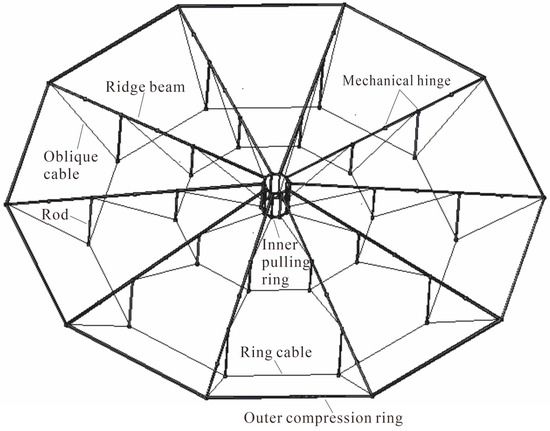
Figure 1.
Axonometric drawing of the RCD structure.
3. Establishment of the Finite Element Model
3.1. Basic Assumptions
The following basic assumptions are made for the finite element models:
(a) The ridge beams and inner tension ring are subjected to both axial force and bending moment by establishing pretension forces through passive tensioning in advance during the prestressing construction stage.
(b) A cable is an ideal flexible body during static loading stages, regardless of the bending stiffness [20]. All the cables are tensioned to build the prestress level and the integral stiffness of the entire structure.
(c) Ideal spherical hinges are set for the connections between cables and rods, cables and ridge beams, and rods and ridge beams to deliver only axial force in adjacent components and to ensure the ideal transmission mode of the bottom cable–strut system.
(d) There are two connecting states between adjacent ridge beams, namely, rigid connection and articulated connection. Considering that during the construction process, the middle-span mechanical joints of ridge beams are set to be hinged to fulfil the deformation requirements and to complete the non-bracket integral tow-lifting extension construction, while the middle-hinged joints will enlarge the local deformation of ridge beams under heavy static loads, rigid midpoint joints are suitable for ridge beams under normal use stages. In this case, all the midpoint joints are set rigid to simulate the static loading state of these members, and all the ends of the tension beams are hinged with their vertical bending moment released to reduce nodal bending stress in this study.
ANSYS 15.0 is used to establish the basic dome research models. A three-dimensional two-node cable element (LINK10), which can bear only tensile force, is used for cables. A three-dimensional two-node spar element (LINK8), which can bear both compressive force and tensile force, is used for the rods. A three-dimensional two-node beam element (BEAM188), which includes shear-deformation effects, stress stiffness, and large deflection, is used for ridge beams, inner rigid rings, and members of single-layer reticulated shells.
3.2. Iterative Force Analysis and Component Optimization Process
According to the above assumptions, an APDL program for iterative force-finding analysis and model optimization is compiled. The detailed process consists of four parts: (1) build the initial numerical models by adding the node coordinate information, material parameter information and boundary condition information and refer to relevant engineering cases. (2) Establish the initial pretension system of cables by experience (i.e., taking 10~20% of the strain of breaking force of each cable as its initial strain) and conduct geometrically nonlinear static analysis of the entire structure in APDL of ANSYS. (3) Extract the variation in the strain of each cable, Δε(i) = ε(i) – ε(i−1), before and after the ith static analysis, and compare it with the convergence threshold, δ. If Δε > δ, the variation in strain of several cables does not match the convergence threshold, then add the variation in strain of each cable Δε(i) to its initial strain, and restart the static analysis. Otherwise, if Δε < δ, the variation in the strain of each cable matches the convergence threshold, and then the prestress distribution of the entire cable-strut system is output. (4) Check the design principles of the numerical model. If not matched, the cross-sectional dimensions of the cables, rods, and beams are changed according to the design principles. Then, the initial numerical model is rebuilt, and the iterative force-finding analysis is restarted. Otherwise, if they match, the process is completed.
The calculation process is shown in Figure 2.
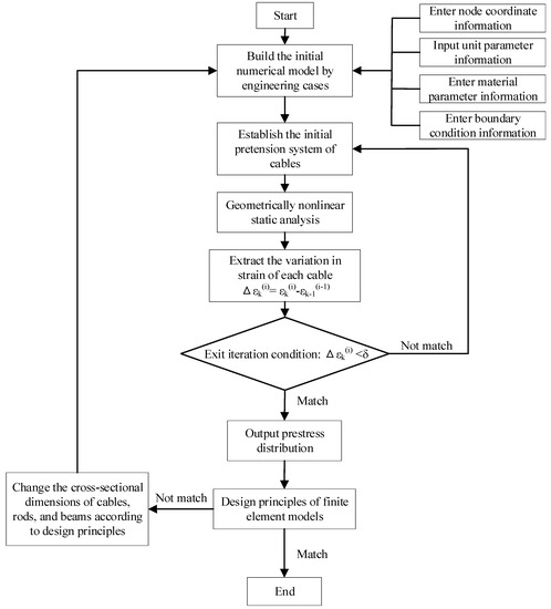
Figure 2.
Flowchart of iterative force-finding analysis and model optimization.
3.3. Design Principles for Numerical Models
In the process of establishing the finite element model, sectional specifications of cables, rods, and steel beams need to be optimized to withstand the roof load. The design principles are as follows:
(1) According to “Standard for design of steel structures” (GB 50017-2017) [21], the vertical displacements of the top ends of rods are smaller than L/250 (L is the structural span) under the serviceability limit state.
(2) Under the ultimate limit state, the maximum axial tensile force of the cables does not exceed 40% of the breaking force (i.e., 80% of the design strength), and the equivalent stress of the steel beams does not exceed 80% of the design value of its yield strength (i.e., 80% of the design strength).
(3) According to the relevant provisions of “Standard for design of steel structures” (GB 50017-2017) [21], the calculation length coefficient of the rods and articulated steel pipes is 1.0, and the maximum compression forces of these components do not exceed their buckling loads, as listed in Equation (1).
where N, φ, A, and f represent the axial compression force, stability factor, cross-sectional area, and yield strength of the member, respectively.
(4) In reality, connection nodes with large dead weights are generally set between cables and rods or beams and cables to guarantee the integrity of the structure. According to Dong et al. [22], the dead weight of all the connecting nodes is equal to 30% of all the other components. This load is distributed on average to both nodes of the rods.
3.4. Building of the Finite Element Model
ANSYS 15.0 software is used to establish the finite element models of the suspen-dome, conventional cable dome, and RCD. These models are 60 m in span, 6 m in height, 3 pieces in ring, and 12 pieces in radial direction. Planar views of the finite element models are shown in Figure 3, elevation views of these models are shown in Figure 4, and material properties and element selections can be found in Table 1.
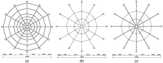
Figure 3.
Planar view of the finite element models (mm). (a) Suspen-dome; (b) cable dome; (c) RCD.
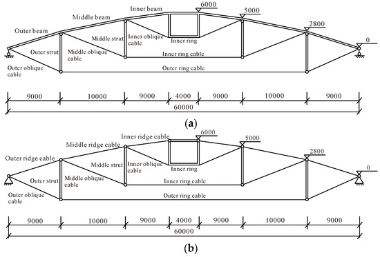
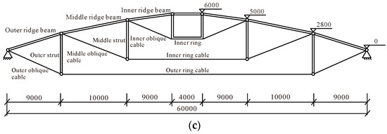
Figure 4.
Elevation view of the finite element models (mm). (a) Suspen-dome; (b) cable dome; (c) RCD.

Table 1.
Component specifications and axial forces in the self-weight equilibrium state (excluding roof weight).
4. Stability Method and Analysis Procedure
The following standard values for loads are considered.
(1) Dead load: the self-weight of the rigid roofing system (including the weight of the inspection passage, lamps, etc.), which is a uniform load on the roof and defined as 0.8 kN/m2.
(2) Live load: the uniform load on the roof, defined as 0.5 kN/m2.
The specific steps of stability analysis are as follows:
① Eigenvalue buckling analysis. Obtain the linear buckling modes and eigenvalues of the models based on Equation (2);
where λ is the eigenvalue; {ψ} is the displacement vector; [Ke] is the linear elastic stiffness matrix; [Kg] is the geometric stiffness matrix.
② Geometric nonlinear stability analysis without an initial defect. Nonlinear stability analysis is conducted to obtain more reliable buckling loads by the load–deflection curves from the nonlinear finite element analysis. The Newton-Raphson method [23] is used to carry out the nonlinear stability analysis of the models based on nonlinear finite element theory, considering the influence of large deformation and stress stiffening.
③ Geometric nonlinear stability analysis with an initial defect. On the basis of Step 2, take the first-order vibration modes as the distribution mode of initial defects [24] and set the maximum value as 1/300 diameter of the entire structure (i.e., 200 mm), according to the provisions of “Technical specifications for space frame structures” (JGJ 7-2010) [25].
④ Geometric and material nonlinear stability analysis with initial defects. On the basis of Step 3, set the yield strength of the steel member except for the cables, and consider the double nonlinear stability analysis (i.e., material nonlinear and geometric nonlinear) of the overall structure with initial defects. The constitutive relationship of steel members adopts a double broken line model, and the elastic modulus after yield is 3% of its value before yield. See Table 2 for specific values.
Table 2.
Material parameters of members before and after yielding.
During the normal use stages, the dead load is constant, while the live load is variable. Therefore, in this study, the dead load and prestress of these three models are set as quantitative, and the roof live load is set as a variable. Two types of live load arrangements are considered, namely, full-span live load and half-span live load. The instability modes are then obtained according to the arrangements of the live load and listed in Table 3.
Table 3.
Load combination.
5. Results and Discussion
5.1. Comparative Study of Eigenvalue Buckling Analysis
The first four eigenvalues and their corresponding buckling modes of these three models are displayed in Table 4 and Table 5 to reflect the eigenvalue buckling analysis of these three structures under load combinations I and II, respectively.
Table 4.
Eigenvalues and buckling modes under load combination I.
Table 5.
Eigenvalues and buckling modes under load combination II.
Under load combination I, the first-order buckling modes of the suspen-dome, cable dome, and RCD exhibit overall vertical bending and depression, local oversized depression of ridge cables, and overall torsional deformation, respectively, with eigenvalues of 7.52, 20.8, and 8.19. The first four eigenvalues of the conventional cable dome are invariably the largest, while the values of RCD are relatively closer to those of the suspen-dome, reflecting similar structural stiffness.
Under load combination II, the first-order buckling modes of these three structures are out-of-plane inversion of the live-load loaded area, horizontal translation deformation towards the live-load loaded area, and local torsional deformation in the live-load loaded area, with eigenvalues of 8.38, 22.9, and 9.21, respectively. The first four eigenvalues of the conventional cable dome are still the largest, while the values of RCD are relatively closer to those of the suspen-dome, reflecting similar ultimate bearing capacities under asymmetric loading cases.
5.2. Comparative Study of Nonlinear Stability Analysis
Nonlinear stability analysis considers three working conditions: geometric nonlinear analysis of a nondefect structure, geometric nonlinear analysis of a defective structure, and dual nonlinear (geometric nonlinear + material nonlinear) analysis of a defective structure. Table 6 lists the ultimate load amplification coefficients (i.e., ultimate load amplifications on the basis of overall stability) and instability modes of the above three conditions. Figure 5 shows the curves of vertical deformation versus load amplification coefficient, Figure 6 displays the curves of cable force versus load amplification coefficient, and Figure 7 illustrates the curves of axial force of ridge beam versus load amplification coefficient. Based on the above nonlinear stability analysis, the following conclusions are drawn:
Table 6.
Ultimate load amplification coefficients for two load combinations of three models.
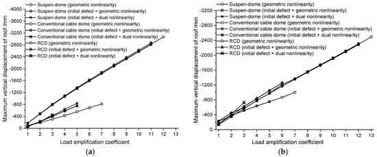
Figure 5.
Curves of maximum vertical deformation versus load amplification coefficient. (a) Load combination I; (b) load combination II.
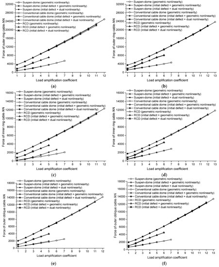
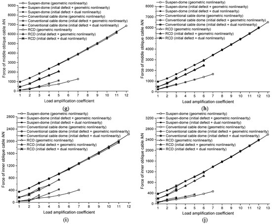
Figure 6.
Curves of load amplification coefficient versus cable force. (a) Outer ring cable for load combination I; (b) outer ring cable for load combination II; (c) inner ring cable for load combination I; (d) inner ring cable for load combination II; (e) outer oblique cable for load combination I; (f) outer oblique cable for load combination II; (g) middle oblique cable for load combination I; (h) middle oblique cable for load combination II; (i) inner oblique cable for load combination I; (j) inner oblique cable for load combination II.
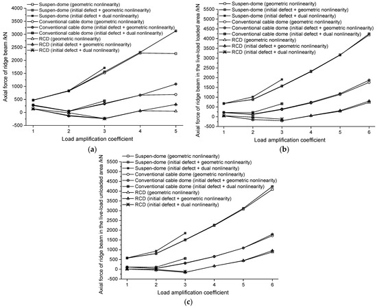
Figure 7.
Curves of the load amplification coefficient versus the axial force of the ridge beam. (a) Load combination I; (b) live-load loaded area for load combination II; (c) live-load unloaded area for load combination II.
(1) The unstable loads of these three structures all follow the law: dual nonlinear analysis considering the initial defect < geometric nonlinear analysis considering the initial defect < geometric nonlinear analysis without the initial defect < eigenvalue buckling analysis. Therefore, it is necessary to comprehensively consider the effects of geometric nonlinearity, material nonlinearity, and initial defects in the stability analysis of dome structures.
(2) Under load combination I, an excessive depression in the middle area of the upper single-layer reticulated shell of the suspen-dome results in instability, and excessive local deformation occurs in the middle area of the inner ridge cables of the conventional cable dome, resulting in instability, and the bearing mode of the inner ridge beams changes from tension bending to compression bending, resulting in torsional instability of the RCD.
(3) Under load combination II, the out-of-plane overturning and sagging exhibited in the live-load loaded area of the single-layer reticulated shells of the suspen-dome results in instability, excessive local deformation appears in the inner ridge cables of the live-load loaded area of the conventional cable dome, resulting in instability, and the bearing mode of components in the live-load loaded area changes from tension bending to compression bending, resulting in instability of the RCD.
(4) Under the same conditions, the ultimate load amplification coefficients of the conventional cable dome are higher than those of the RCD and suspen-dome, while the vertical displacements of the conventional cable dome are also much larger than those of the latter two.
(5) Under the same load combination, the maximum vertical displacements of the RCD and suspen-dome, considering dual nonlinear and initial defects, are significantly larger than those of the other models, while the cable forces of the RCD are insensitive to these influencing factors.
(6) When applying 2–3 times the roof loads, the loading slopes of the oblique cable force, the ring cable force, and the maximum vertical displacement of the RCD vary significantly. Large overall deformation occurs, the sudden sinking of the upper ridge beam grid takes place, and the entire structure becomes relatively flatter than its initial form. In this case, the lengths of the upper ridge beams are shortened, the bearing mode of the inner ridge beams that possess the smallest pretension forces in the prestressed state transforms from tension bending to compression bending, and the equilibrium configuration of the entire structure changes considerably. In this process, the RCD transforms from an initial unstable static equilibrium state to unstable dynamic equilibrium state and finally reaches the stable static equilibrium state; namely, the whole structure experiences the redistribution of internal forces.
(7) Considering dual nonlinearities and initial defects, the minimum ultimate load amplification coefficients of the suspen-dome, conventional cable dome, and RCD all appear in load combination I, with specific values of 3.3, 11.0, and 3.0, respectively. According to “Technical specifications for space frame structures” (JGJ 7-2010) [25], the safety factor K should be greater than 2 when analyzing the elastic-plastic process. The stabilities of the three structures can meet the requirements of this regulation.
6. Conclusions
In this study, linear eigenvalue buckling analysis and nonlinear stability analysis are carried out for suspend-domes, conventional cable domes, and RCDs. The following conclusions are drawn:
(1) The unstable loads of these three structures follow: dual nonlinear analysis with initial defect < geometric nonlinear analysis considering initial defect < geometric nonlinear analysis without initial defect < eigenvalue buckling analysis. Therefore, geometric nonlinearity, material nonlinearity, and initial defects should be considered simultaneously in the stability analysis to consider the effect of eccentric axial force, elastoplasty of materials, and second-order effects of static loads on the stability capacity of dome structures.
(2) The instability mode of RCD depends on the loading forms, and the instability phenomenon first occurs in the heavy loading area. When applying ultimate static loads, large nodal deformation occurs, the sudden sinking of the upper ridge beam grid takes place, and the structure becomes relatively flatter than its initial form. In this case, the lengths of the upper ridge beams are shortened, the bearing mode of the inner ridge beams that possess the smallest pretension forces in the prestressed state transforms from tension bending to compression bending, and the equilibrium configuration of the entire structure changes considerably. Specifically, under the combination of “full-span dead load + full-span live load”, the inner ridge beams of the RCD change from tension bending to compression bending, which causes torsional instability of the entire structure. Nevertheless, under the combination of “full-span dead load + half-span live load”, the ridge beams of RCD in the live-load loaded area change from tension bending to compression bending, and local out-of-plane instability occurs.
(3) When considering initial geometric defects and material nonlinearity, the ultimate stable bearing capacities of the RCD and suspen-dome both significantly decrease, indicating that these two structures are more sensitive to initial geometric defects and material nonlinearity.
(4) The linear eigenvalues and ultimate load amplification coefficients of the RCD are close to those of the suspen-dome, while their vertical displacements are much smaller than those of the conventional cable dome, indicating that the RCD has sufficient stiffness to reduce local displacement.
(5) Under 2–3 load combinations, internal ridge beams change from a tensile-bending state to a compressive-bending state, causing the overall instability of RCD afterwards. In this case, the timing at which ridge beams change from tension to compression is a key factor determining the overall stability of RCD.
(6) The effect of the initial defect, geometric nonlinearity, and material nonlinearity must be proper during the stability calculation. If the corresponding structural design is not safe or economical, further investigation is needed.
(7) As a natural extension of this research, while the manuscript provides valuable insights into the stability performance of ridge-beam cable domes (RCDs) under vertical load, it would be beneficial to include suggestions for future research directions. This could involve identifying specific areas or aspects that were not covered in the current study but hold potential for further investigation.
Author Contributions
Conceptualization, Y.J. and M.D.; Data curation, L.W. and Y.R.; Formal analysis, M.D.; Investigation, Y.J. and L.W.; Methodology, Y.J.; Project administration, M.D.; Resources, B.L.; Software, M.D.; Supervision, L.W.; Validation, B.L.; Visualization, Y.R.; Writing—original draft, Y.J. and M.D.; Writing—review and editing, M.D. All authors have read and agreed to the published version of the manuscript.
Funding
This research was funded by the National Natural Science Foundation of China, grant number 11673039; the Natural Science Foundation of Jiangsu Province, grant number BK20190753; the Natural Science Foundation of the Jiangsu Higher Education Institutions of China, grant number 18KJB560011; the Priority Academic Program Development of Jiangsu Higher Education Institutions (PAPD). The APC was funded by the Natural Science Foundation of Jiangsu Province, grant number BK20190753.
Institutional Review Board Statement
Not applicable.
Informed Consent Statement
Not applicable.
Data Availability Statement
The data presented in this study are available on request from the corresponding author.
Conflicts of Interest
The authors declare no conflict of interest.
References
- Dong, F.; Gao, J.; Hao, A.; Wei, Y.; Huang, X.; Shi, F.; Zheng, K. A New Approach to Symmetry Reliability: Combination of Forward and Inverse Reliability Principle and Its Application to Frame Structures and Bamboo Bridges. Symmetry 2022, 14, 318. [Google Scholar] [CrossRef]
- Song, K.; Scarpa, F.; Schenk, M. Form-finding of tessellated tensegrity structures. Eng. Struct. 2022, 252, 113627. [Google Scholar] [CrossRef]
- Kato, S.; Takiuchi, Y.; Abe, K.; Mukaiyama, Y.; Nakazawa, S. Effectiveness of buckling restrained braces for upgrading earthquake resistant capacity of single layer grid dome. Eng. Struct. 2022, 261, 114280. [Google Scholar] [CrossRef]
- Estephan, J.; Feng, C.; Chowdhury, A.G.; Chavez, M.; Baskaran, A.; Moravej, M. Characterization of wind-induced pressure on membrane roofs based on full-scale wind tunnel testing. Eng. Struct. 2021, 235, 112101. [Google Scholar] [CrossRef]
- Huo, L.; Qi, H.; Chen, C.; Pan, L. Wind-Induced Interference of a Rectangular-Section Building on the Dome-Roof. Int. J. Struct. Stab. Dyn. 2022, 22, 2240017. [Google Scholar] [CrossRef]
- Lu, Z.; Li, X.; Liu, R.; Xue, S.; Zhao, Z.; Jing, H.; Fan, Q.; Liu, T.; Dezhkam, M. Shaking table experimental and numerical investigations on dynamic characteristics of suspend-dome structure. Structures 2022, 40, 138–148. [Google Scholar] [CrossRef]
- Zhao, Y.; Guo, J.; Jiang, Z.; Chen, W.; Zhou, G. Control method for determining feasible prestresses of cable-struts structure. Thin Walled Struct. 2022, 174, 109159. [Google Scholar] [CrossRef]
- Wu, C.; Yang, Y.; Gou, B.; Wu, J. Research on a multipoint impact test of single-layer spherical reticulated shell. J. Constr. Steel Res. 2021, 186, 106897. [Google Scholar] [CrossRef]
- Zong, Z.; Guo, Z. Nonlinear Numerical Analysis of Cable Dome Structure with Rigid Roof. Eng. Mech. 2009, 26, 134–139. [Google Scholar] [CrossRef]
- Luo, B.; Ding, M.; Pan, J.; Guo, Z.; Ruan, Y. Mechanical performance study of three joints tension-beam Geiger type cable dome structure. J. Build. Struct. 2016, 37, 61–67. [Google Scholar] [CrossRef]
- Ding, M.; Luo, B.; Guo, Z.; Pan, J. Integral tow-lifting construction technology of a Ridge beam-cable dome. J. Zhejiang Univ. Sci. A 2015, 16, 935–950. [Google Scholar] [CrossRef]
- Pan, J. Initial Form and Structural Behavior Analysis on Cable Dome of Rigid Roof Supported by Single-Layer Cable. Master’s Thesis, Southeast University, Nanjing, China, 2014. [Google Scholar]
- Ding, M.; Luo, B.; Pan, J.; Guo, Z. Experimental Study and Comparative Analysis of a Geiger-type Ridge-beam Cable Dome Structure. Int. J. Civ. Eng. 2018, 16, 1739–1755. [Google Scholar] [CrossRef]
- Zuo, Q. Research on the Performance Analysis and the Key Technology of Construction of Levy-Patterned Tensile-Beam Cable Dome. Master’s Thesis, Southeast University, Nanjing, China, 2017. [Google Scholar]
- Dong, F.; Shi, F.; Wang, L.; Wei, Y.; Zheng, K. Probabilistic Assessment Approach of the Aerostatic Instability of Long-Span Symmetry Cable-Stayed Bridges. Symmetry 2021, 13, 2413. [Google Scholar] [CrossRef]
- Wang, Y.; Gu, Y.; Liu, J. A domain-decomposition generalized finite difference method for stress analysis in three-dimensional composite materials. Appl. Math. Lett. 2020, 104, 106226. [Google Scholar] [CrossRef]
- Kabir, H.; Aghdam, M.M. A robust Bézier based solution for nonlinear vibration and post-buckling of random checkerboard graphene nano-platelets reinforced composite beams. Compos. Struct. 2019, 212, 184–198. [Google Scholar] [CrossRef]
- Bert, C.W.; Malik, M. Differential quadrature: A powerful new technique for analysis of composite structures. Compos. Struct. 1997, 39, 179–189. [Google Scholar] [CrossRef]
- Chen, Y.; Hu, Z.; Zhu, B.; Tong, G.; Guo, Y.; Wang, J. Stability design of axially loaded stringer-stiffened moderately-thick cylindrical shells in steel tubular transmission towers. Thin Walled Struct. 2022, 172, 108874. [Google Scholar] [CrossRef]
- Duan, M.; Suo, X.; Dong, F.; Li, J.; Li, G. Research on the Control Method for the Reasonable State of Self-Anchored Symmetry Suspension Bridge Stiffening Girders. Symmetry 2022, 14, 935. [Google Scholar] [CrossRef]
- GB 50017-2017; Code for Design of Steel Structures. The National Standards of the People’s Republic of China: Beijing, China, 2017. (In Chinese)
- Dong, S.; Wang, Z.; Yuan, X. A Simplified Calculation Method for Initial Prestress of Levy Cable Domes with the Consideration of Self-Weight. Eng. Mech. 2009, 26, 1–6. [Google Scholar]
- Guo, J. Research on distribution and magnitude of initial geometrical imperfection affecting stability of suspen-dome. Adv. Steel Constr. 2011, 7, 344–358. [Google Scholar]
- Cui, X.Z.; Li, Y.G.; Hong, H.P. Effect of spatially correlated initial geometric imperfection on reliability of spherical latticed shell considering global instability. Struct. Saf. 2020, 82, 101895. [Google Scholar] [CrossRef]
- JGJ 7-2010; Technical Specification for Spatial Grid Structure. The National Standards of the People’s Republic of China: Beijing, China, 2010. (In Chinese)


Disclaimer/Publisher’s Note: The statements, opinions and data contained in all publications are solely those of the individual author(s) and contributor(s) and not of MDPI and/or the editor(s). MDPI and/or the editor(s) disclaim responsibility for any injury to people or property resulting from any ideas, methods, instructions or products referred to in the content. |
© 2023 by the authors. Licensee MDPI, Basel, Switzerland. This article is an open access article distributed under the terms and conditions of the Creative Commons Attribution (CC BY) license (https://creativecommons.org/licenses/by/4.0/).