Abstract
Thin-walled galvanized helical corrugated steel tubes (HCSTs) filled with concrete are promising composite members, consisting of concrete, an anti-corrosion shell, and a multifunctional exterior corrugated steel tube. To investigate the synergistic working mechanism of concrete-filled HCSTs (CFHCSTs), six specimens were designed for axial compression tests, with the inner diameter of the column and the volumetric steel ratios of the longitudinal reinforcement as the variation parameters. The results show that HCSTs can better confine the concrete core and increase its strength. The failure mode of HCSTs is significantly influenced by the column’s diameter, and those with a smaller diameter are prone to slide failure and lock seam tearing. The strains and stresses on HCSTs are discussed in detail to elucidate the confinement effect. This paper proposes a suitable design method to predict the ultimate axial compression load capacity of CFHCST columns based on early studies on steel tube-confined concrete.
1. Introduction
Concrete-filled steel tube (CFST) columns have been widely used as the load-bearing members of high-rise and super high-rise buildings [1], long-span bridges [2], industrial plant columns [3], and subway platform columns [4] in recent years. The use of CFST columns has been proven to be an effective method for improving structural properties, such as strength and stiffness [5,6]. However, due to various factors, such as changes in a structure’s use, changes in the environment, damage or degradation of the existing structure, seismic loads, etc., CFST columns often require improvements to address their low ductility, local buckling, and corrosion resistance. Concrete-filled corrugated steel tubular (CFCST) composite columns are considered to be an effective solution [7,8].
Corrugated steel tubes (CST/CSP) are mechanically rolled from standard hot-dip galvanized steel plates. Corrosion is prevented by a zinc oxide film and the iron cathodic protection produced on the surface of the CST [9]. Furthermore, coatings that are difficult to remove can be used, considerably lowering the cost of regular maintenance and extending the life of the CST structure. CSTs outperform typical flat steel tubes in terms of corrosion resistance, energy dissipation, and stiffness-to-weight ratio [7,8,9]. CSTs are frequently used in highway soil steel bridges [10], infrastructure reinforcement [11,12], accelerated bridge construction [13], and other applications due to their ease of manufacturing. The benefits of adopting CSTs in civil engineering include: (a) ease of handling and installation; (b) corrosion resistance as a protective layer for the concrete core; (c) increased section stiffness and second moment of inertia; and (d) time and manpower savings for concrete permanent templates [7,8,9,10,11,12,13]. According to the manufacturing technique, CSTs can be classified as welding or lock seam connection. A welded CST can be formed into an annular corrugated steel tube (ACST) with a 0° angle. A CST with a lock seam connection is often fashioned into a helical corrugated steel tube (HCST) with a helical angle of 3° to 38°, depending on the diameter of the tube. Different types of connections have different force modes and load transfer processes. Comparing the manufacturing processes of ACSTs and HCSTs, HCSTs adopt a seam lock connection, which does not require much welding and has the advantages of green environmental protection and rapid manufacturing. Importantly, HCSTs avoid possible residual stress problems caused by extensive welding.
Several studies have investigated the performance of concrete-filled steel tubes in different configurations. Su et al. [14] found that external ACSTs provide adequate circumferential confinement for the concrete core, but local buckling of the inner flat steel tube can negate the benefits of an outer ACST. Wang et al. [8] demonstrated that concrete-filled HCSTs have somewhat superior axial compression performance compared to that of flat circular tube-confined concrete columns. Wang et al. [15] found that embedding structural steel in the interior of concrete-filled HCST columns could improve their local stability and post-peak behavior, even without transverse reinforcement. Yang et al. [16] discovered that eccentric compression alters the confinement depth of CSTs in the column cross-section. Fang et al. [17] analyzed the axial compression performance of concrete-filled HCST short columns with a large helical angle (37.5°), and concluded that the helical angle influences the working mechanism of the short column and reduces the combined effect of the HCST and concrete core. Additionally, Liu et al. [7] studied the axial compression performance of rubber concrete-filled ACST short columns, and found that ACSTs could successfully restrict the rubber concrete core while also improving its strength. Rubber concrete can work with an ACST to improve the overall ductility of a structure, as they can both “gain” and “compensate” for each other. In addition, Li et al. studied the buckling and stability performance of hoop restraint effects, and the research results can be applied to constrained arch and ring models [18,19,20,21,22].
In a recent paper, Liu et al. [7] investigated the axial compressive behaviors of ACST columns filled with concrete. However, it is important to conduct additional experimental research on concrete-filled HCSTs, since the manufacturing processes for HCSTs and ACSTs differ significantly from each other. Moreover, practical engineering applications will involve larger-diameter, concrete-filled HCST composite columns with appropriate longitudinal reinforcement. Due to the helical angle of HCSTs, larger diameter columns may exhibit distinct failure modes and load transmission processes compared to smaller diameter columns. However, existing research on the axial compression of concrete-filled HCSTs does not consider the fact that the helical angle decreases as the column diameter increases [8,17,23,24].
This study focuses on conducting experimental and numerical research to investigate the axial compression performance of large-diameter HCSTs filled with concrete. The research includes the testing of six stub columns, with one column serving as a flat-tube-confined concrete reference for comparison. The primary variables examined in this study are the inner diameter of the column, which affects geometrical changes in the HCST, and the volumetric steel ratios of the longitudinal reinforcement. This study evaluates and discusses various aspects, including the failure modes, load–vertical strain curves, lateral deformation properties, stress characteristics, and core concrete shear directions of the specimens. Additionally, this study reveals the operating mechanism of large-diameter specimens and the synergistic force interaction between concrete and helical CSTs. Finally, based on the test data, a formula for calculating the compressive strength of tube-confined concrete columns is proposed.
2. Experimental Program
2.1. Test Specimens
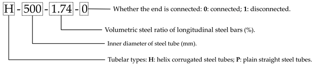
A total of six stub columns, each with a 750 mm height, were subjected to monotonic axial compression loads to investigate the axial mechanical properties of concrete-filled steel tube columns. Specimens with a slenderness ratio below 3.5 did not exhibit bending deformation under an axial compressive load [25]. For this test, the slenderness ratio of the specimens was fixed at 1.5–2.5 due to limitations in the test setup clearance and the geometric size of the helical corrugated steel tubes (HCSTs). Five of the specimens were concrete-filled helical corrugated steel tubes (CFHCSTs), with the main experimental variables including the inner diameter of the column and the resulting geometrical changes in the HCST (300 mm, 400 mm, and 500 mm), as well as the volumetric steel ratios of the longitudinal reinforcement (0%, 1.74%, and 2.87%). In this study, the ends of the steel tubes of specimen P-300-0-1 were disconnected to cut the transmission of the vertical load in the steel tube. The remaining specimen was a concrete-filled plain straight steel tube (PST) column used for comparison. The majority of construction needs can be satisfied by using columns with a diameter ranging from 300 mm to 500 mm. According to the specifications of GB50010-2010 [26], the volumetric steel ratios for the longitudinal reinforcement of the column chosen were within a suitable range.
For convenience, each specimen was named, as illustrated in Table 1. The details of the specimens are presented in Table 1, i.e., the tubular type, corrugation angle (λ), corrugation length (l), corrugation height (h), inner diameter (Din), outer diameter (Dout), nominal diameter (D0), steel tube thickness (t), short column length (L), volumetric steel ratio of the longitudinal and transverse steel bars (ρb and ρs), steel ratio of the steel tube (α), confinement index (ξ), peak load or ultimate load-bearing capacity (Nu), member deformation at peak load (εu), strength index (SI), and ductility index (DI). Figure 1 shows the details of the specimens.

Table 1.
Details of test specimens.
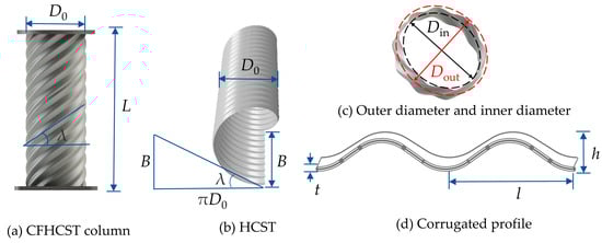
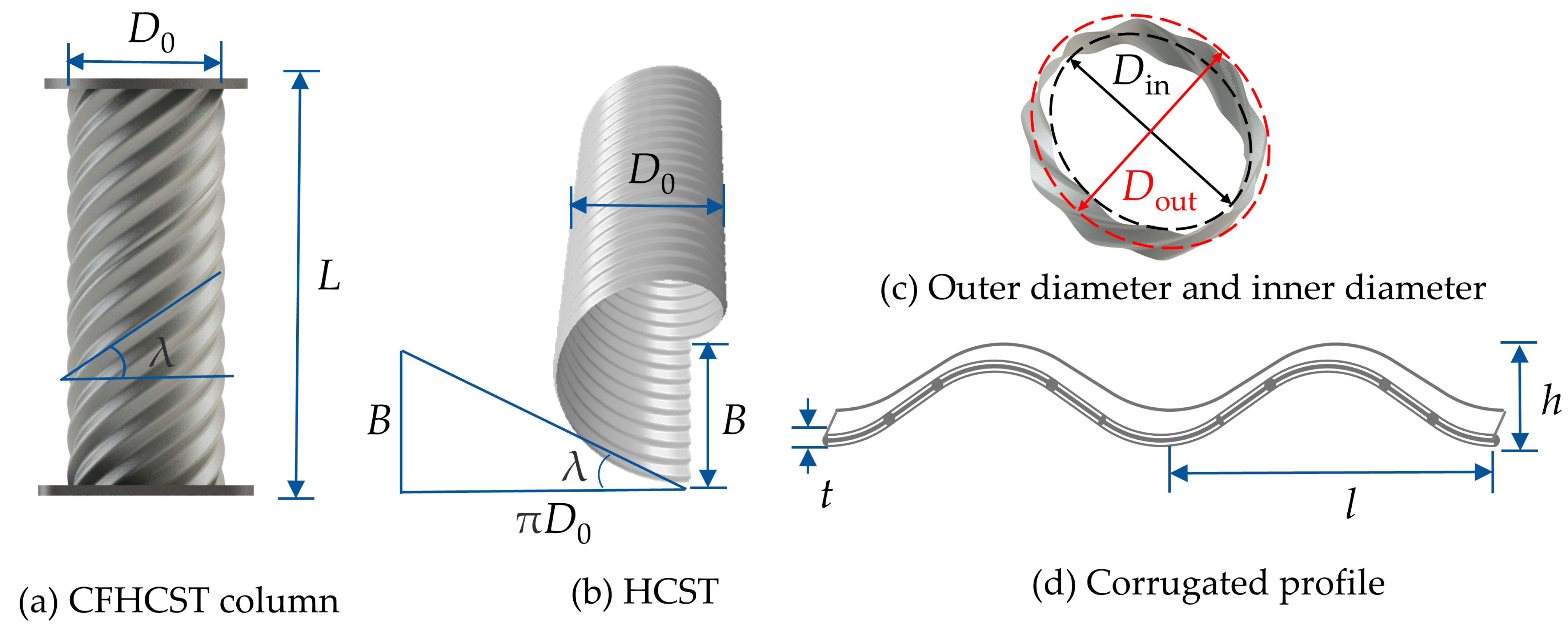
Figure 1.
Details of specimens.
The stirrup arrangement for specimens H-500-0-0, H-500-1.74-0, and H-500-2.87-0 is 4@150 mm, HRB335, with a diameter of 6 mm. The purpose of designing and fabricating these specimens is to study the effect of the volumetric steel ratios of the longitudinal reinforcement on the mechanical properties of the column axial compression. Therefore, the stirrup arrangement is relatively sparse and the diameter of the stirrups is small. The main purpose of the stirrup arrangement is to fix the longitudinal reinforcements, and the volume ratio of the stirrups is calculated to be only 0.09%. The effect of stirrups on the macroscopic mechanical properties of the specimens is very small, and the constraint effect of the stirrups on the concrete can be ignored in the analysis [26].
The definition of the calculation of the outer and inner diameters is illustrated in Figure 1c, owing to the distinctive geometric shape of the HCST. The nominal diameter D0 is calculated using Equation (1).
The calculation method for the helix angle of the HCST is shown in Figure 1b, and the formula is shown in Equation (3).
where B is the width of the strip, that is, the pitch when an HCST is produced.
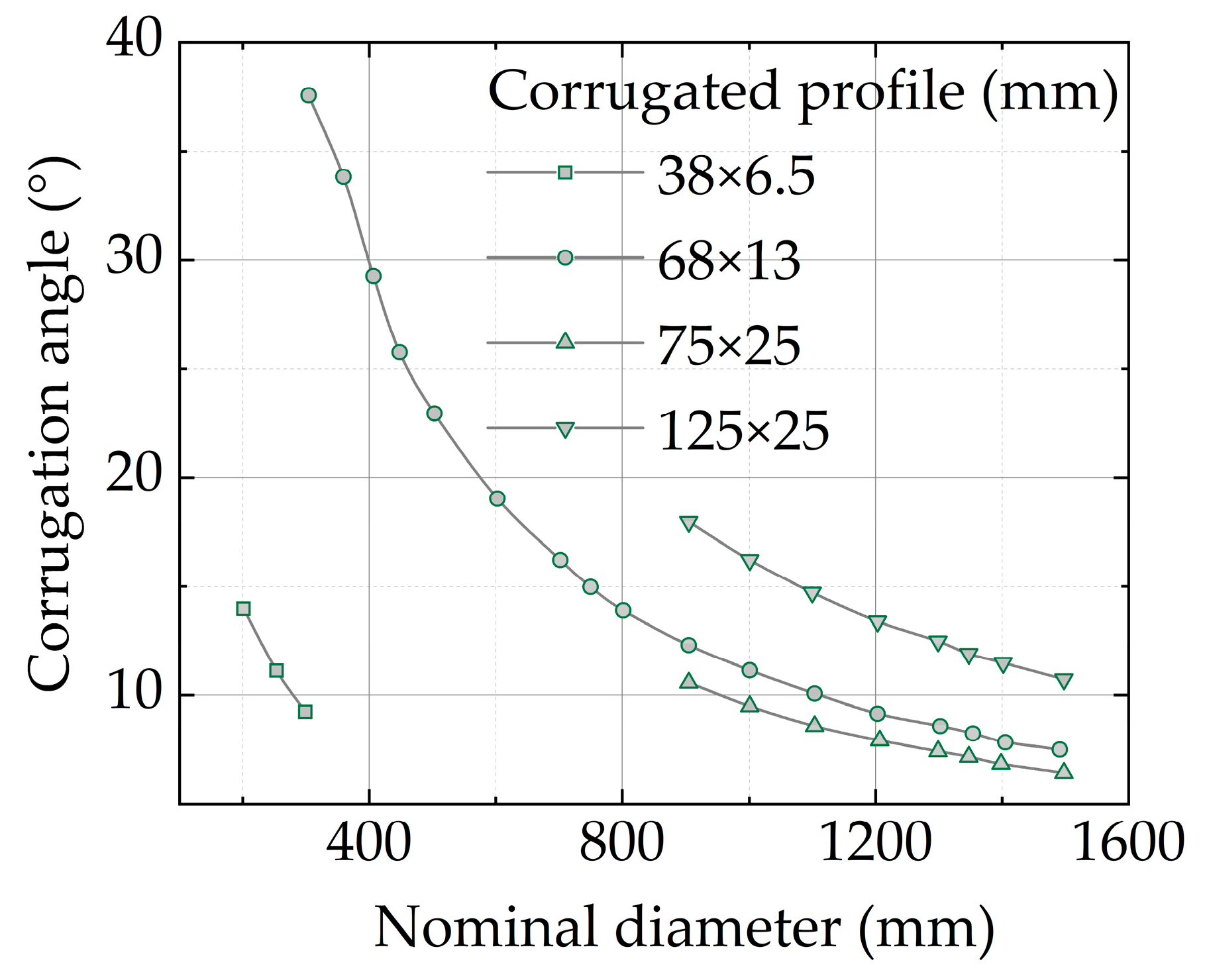
At present, the GB/T 34567-2017 Cold-Formed Corrugated Steel Pipe [27] specifies the specifications and dimensions of the HCST, and the diameter and helix angle of the steel tube corresponding to the recommended HCST specification are shown in Figure 2.
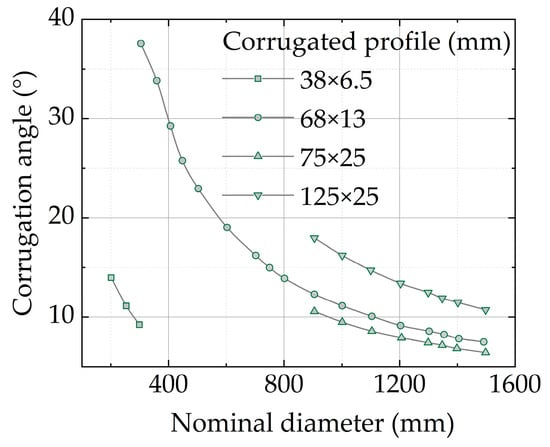
Figure 2.
Relationship between helical angle and calculated diameter of HCST with different corrugated profiles.
Figure 2 shows that the helical angle of the HCST decreases as the calculated diameter increases. The corrugated profile of 68 × 13 mm has the widest range of applicable diameters. There are noticeable differences in the helical angle of the different corrugated profiles, with a reduction in rate of the calculated diameter. When the calculated diameter is 500 mm, the helical angle of an HCST with a corrugated profile of 68 × 13 mm is 21°. As the diameter increases, the rate of decrease in the helical angle decreases significantly. Therefore, the specimens used in this study are CFHCSTs with a corrugated profile of 68 × 13 mm and a maximum calculated diameter of 500 mm. The axial compression mechanical properties obtained from the test can better approximate the mechanical properties of large-scale CFHCST columns used for practical applications.
According to the calculations, HCSTs of the same height consume more steel than plain straight steel tubes. Therefore, the amplification factor ηc is defined to modify the steel ratio α. ηc is defined using Equation (4).
where ηc is the corrugated amplification factor, a plain straight steel tube takes a value of 1, and ws is length of one period of corrugation.
The amplification factors of HCSTs with corrugated profiles of 68 × 13 mm are taken as 1.08. The amplification factor of an ordinary straight steel tube is 1.0. The steel ratio α of the test specimen is defined using Equation (5).
where As and Ac are the cross-sectional areas of the steel tube and core concrete, respectively, and t is the steel tube thickness.
This study utilizes different tubular types; therefore, the confinement index ξ is also quite different. ξ is defined using Equation (6).
where fy is the average yield strength of the steel tube and fcp is the average prism compressive strength of concrete.
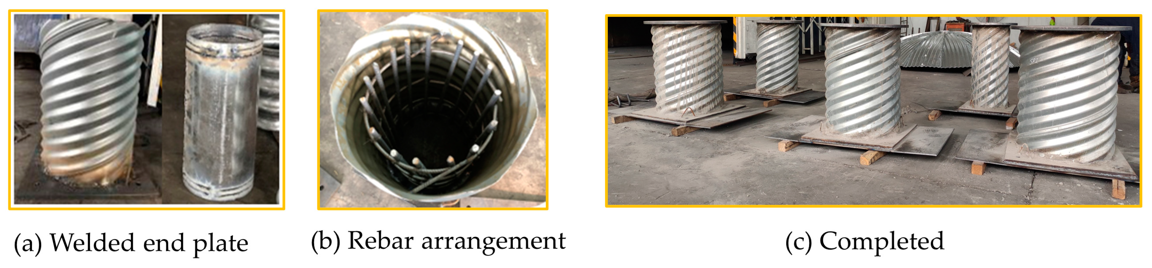
Figure 3 illustrates the production process of the specimens. First, the bottom of the steel tube is welded to the end plate, and the rebar specimen is arranged in the column and fixed in place. Next, the tube is filled with concrete and compacted using a vibrating rod. After pouring, the specimens are cured under standard conditions. Once cured, a self-compacting, high-strength mortar with a strength of C60 is applied to the top of the sample for local reinforcement and leveling. Finally, the end plate at the top of the specimen is welded to the steel tube. It should be noted that for the TRC specimen, a 10 mm slit is cut at the top and bottom of the plain straight steel tube at a distance of 5 cm from the end plate, to ensure that the plain straight steel tube does not directly bear the longitudinal load.

Figure 3.
Test specimen production process.
2.2. Material Properties
Three dog-bone coupons were taken from the crest, trough, waist, and lock seam of the HCST and examined using an electronic universal testing device. The coupons were prepared and tested according to the specifications outlined in GB/T 228-2010 [28]. Figure 4 shows the stress–strain curves and failure modes of the dog-bone specimens. In the elastoplastic stress analysis, the influence of the yield strength at different positions on the HCST was considered. The yield strength of the HCST is shown in Table 2.
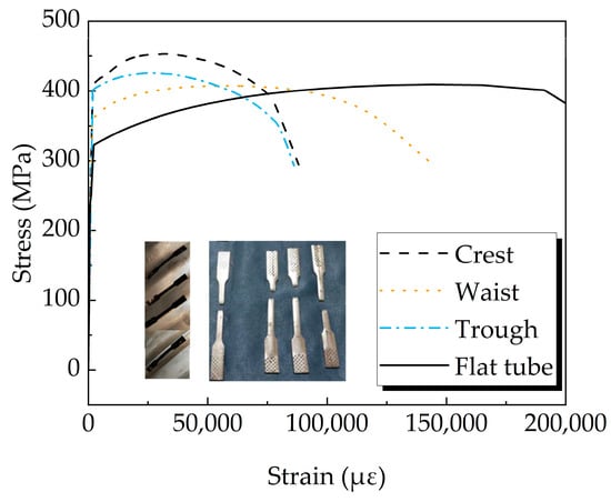
Figure 4.
HCST stress–strain curves at different parts.
Table 2.
Material mechanical properties.
To simplify the analysis, Equation (7) is used to calculate the yield strength of the HCST.
where fy-crest, fy-waist, and fy-trough are the yield strengths of the crest, waist, and trough, respectively. λcrest, λwaist, and λtrough are the ratios of each position to a complete corrugation, and the three values of the 68 × 13 mm corrugation are 0.245, 0.51, and 0.245, respectively.
The concrete selected for this study was conventional commercial concrete with a strength grade of C40. Nine cubic and prismatic concrete test blocks were cast for each batch of concrete. The dimensions of the cube and prism specimens were 100 mm × 100 mm × 100 mm and 300 mm × 100 mm × 100 mm, respectively. The test block and specimen were subjected to the same curing procedure, with a temperature of 21 °C and a humidity of 78%. In the final tests, the cubic and prismatic specimens were examined to determine whether the concrete’s compressive strength met the GB/T 50081-2002 standards [29]. Table 2 presents the concrete test results, i.e., the equivalent values of the cube compressive strength fcu, the prism compressive strength fcp, and the elastic modulus of the concrete Ec.
Two samples were used for the reinforcement, one from the stirrups and the other from the longitudinal reinforcements. They were tested according to GB 1499.2-2018 [30], and the yield strength is shown in Table 2.
2.3. Test Setup and Instrumentation Layout
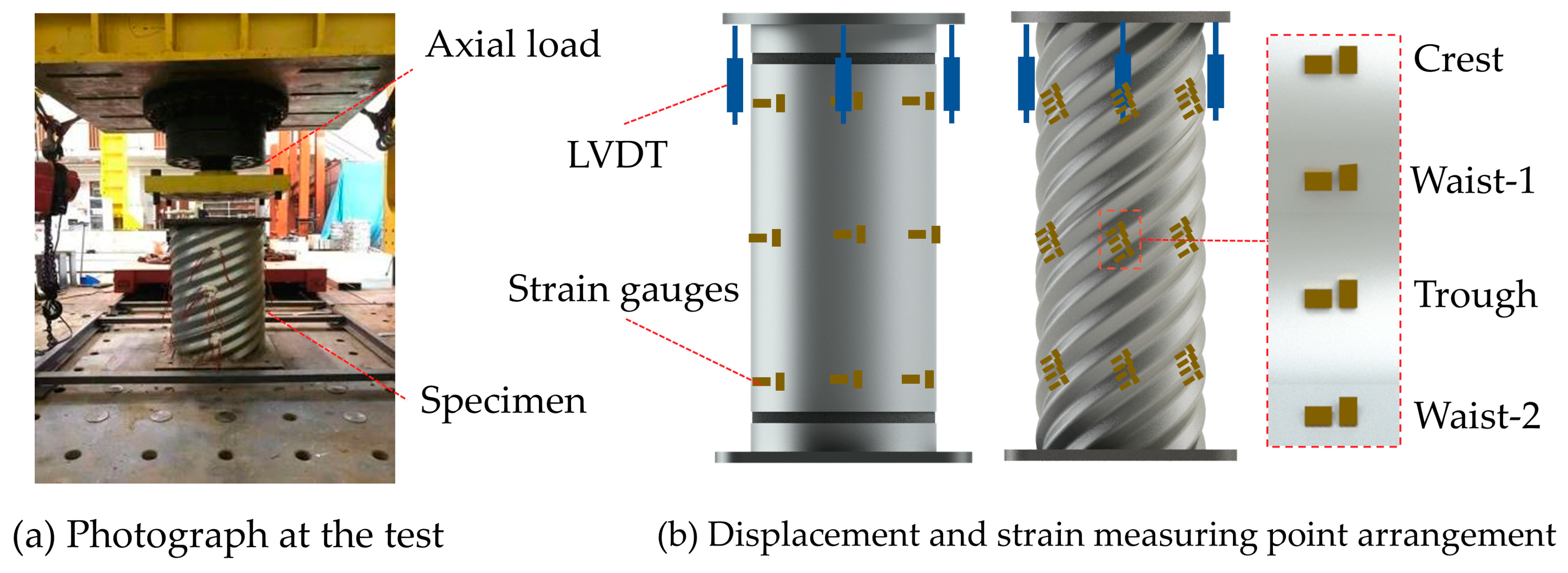
The specimens used in the test had different diameters, with two specimens having a diameter of 300 mm, one specimen having a diameter of 400 mm, and three specimens having a diameter of 500 mm. As a result, the axial load of the specimens will vary greatly. The test was carried out using two different setups. The specimens labeled P-300-0-1, H-300-0-0, and H-400-0-0 were tested on the MTS-1000-ton press, while the specimens labeled H-500-0-0, H-500-1.74-0, and H-500-2.87-0 were tested on a 7500-ton multifunctional compression–shear test system. The test setup is shown in Figure 5a.

Figure 5.
Test setup and instrumentation layout.
The instrumentation used in the test is illustrated in Figure 5b. To obtain the axial deformation of the column, four LVDTs with a measuring range of 50 mm were arranged at 90° intervals around the top surface of the specimen. The 12 strain-measuring areas were symmetrically arranged at 90° circumferential intervals along the upper, middle, and lower sections of the specimen. Additionally, for each strain-measuring area of the specimen, two strain gauges were attached to the longitudinal and transverse directions of the plain straight steel tube (PST), and two strain gauges were also attached to the longitudinal and transverse directions of the crest, waist-1, trough, and waist-2 of the HCST.
Prior to the formal loading, a preloading was performed. During the preloading test, four longitudinal LVDTs were carefully monitored to ensure that the load was applied concentrically to the specimen. Considering the reliability and efficiency of the test, displacement-controlled loading was used in the test, and the loading rate was 0.02 mm/s. The load-holding time was approximately 2–3 min per load interval. The test was stopped when the load dropped to 70% of the ultimate bearing capacity of the specimen, or when the steel tube exhibited obvious local buckling and lock seam tears, indicating that the specimen had failed.
3. Experimental Results and Discussion
3.1. Failure Modes
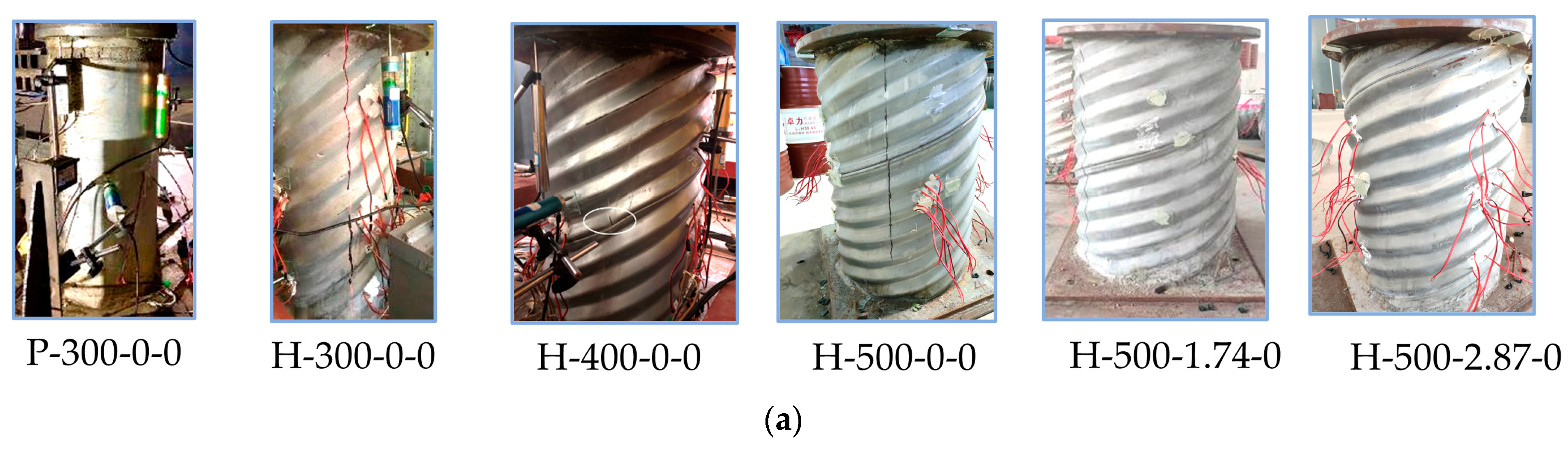
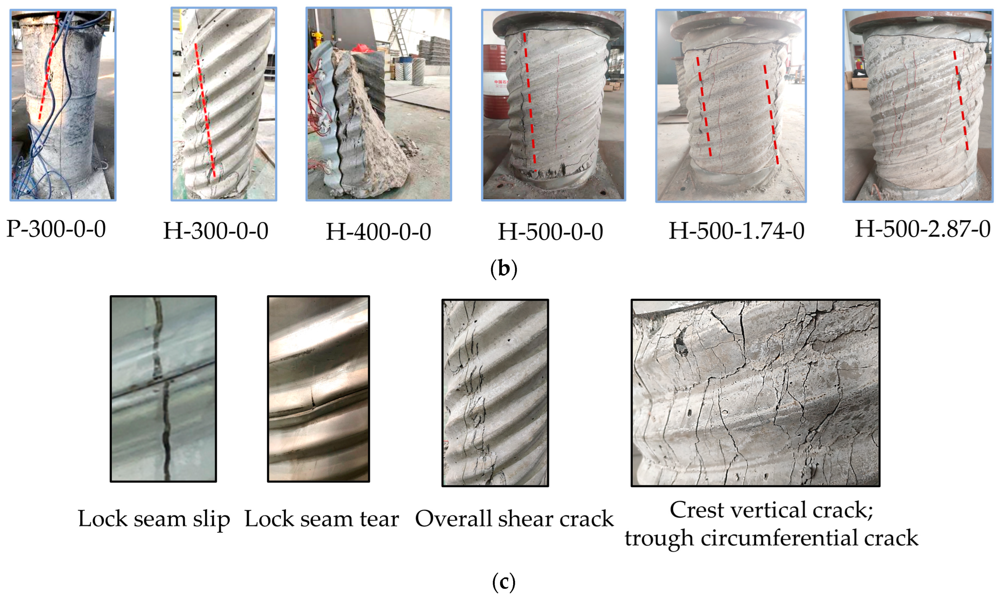
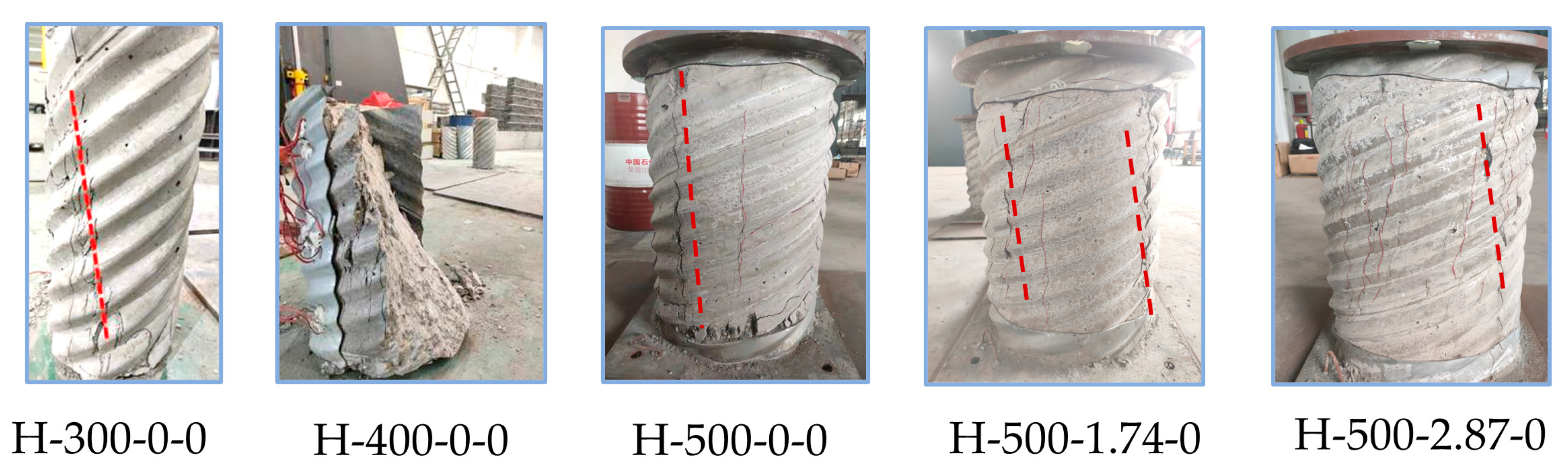
The failure mode of the specimen and the crack distribution of the core concrete are shown in Figure 6. During the test loading process for the CFHCST specimen, the following observations were made:
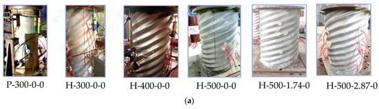
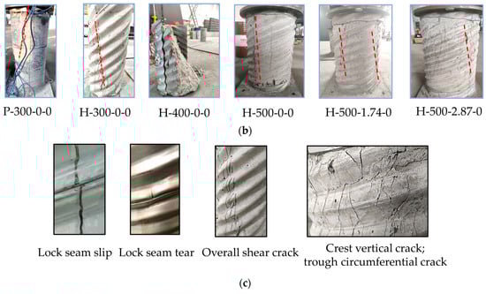
Figure 6.
Cracks distribution and failure mode of specimens. (a) Failure mode. (b) Core concrete cracks. (c) Local failure details.
- Initial Loading Stage: The load and deformation of the specimen increased linearly, with no obvious test phenomenon. The corrugations of the CFHCST specimen were closely engaged with the core concrete, and the deformation was coordinated without visible damage.
- Post-Peak Failure Stage: The bearing capacity of the specimen gradually decreased, requiring a longer time and greater vertical deformation to drop to 85% of the peak load. The middle and upper part of the specimen expanded significantly, compressing the corrugations on the outer surface vertically.
- Failure Process: The failure process entailed the expansion of the core concrete under pressure, followed by an increase in the confinement effect of the HCST on the core concrete. This resulted in severe compression at the HCST ends and substantial lateral expansion deformation of the core concrete, ultimately leading to the slipping and tearing of the HCST lock seam (Figure 6c).
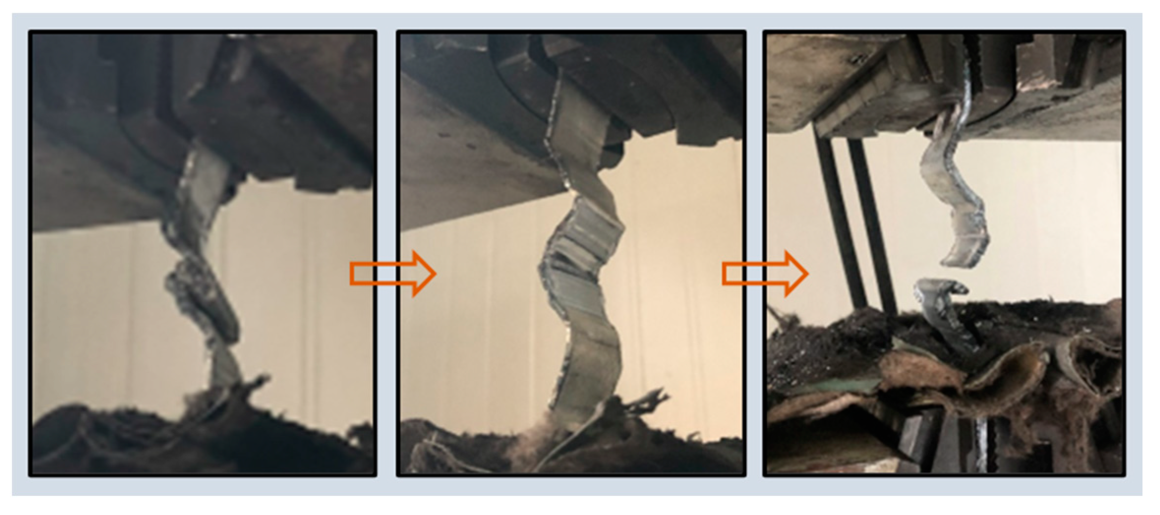
- Damage Mode: After peeling off the specimen, it was observed that the HCST and core concrete were tightly interlocked, with no significant slipping in the concrete. The core concrete underwent shear failure almost perpendicular to the helix angle (Figure 6b). The tensile failure test of the lock seam is shown in Figure 7. The lock seam opened by unfolding, indicating that the dents or bites in the crests and troughs observed during the test were not the strength limit of the plate, but rather a local stress release process. The lock seam strength of the HCST was identified as a key factor affecting the axial compression performance of the CFHCST.
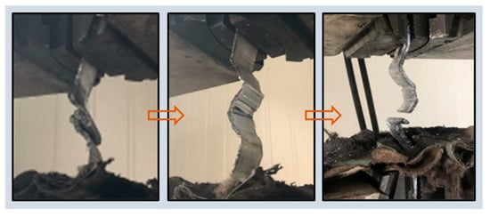 Figure 7. The tensile failure test of the lock seam.
Regarding the PST specimen, its failure is closely related to the stress state of the steel tube. As the axial load increases, the end concrete gradually breaks. The end steel tube buckles outward, and multiple bulges appear in the middle of the column. Multiple local buckling wrinkles appear after about 90% of the peak load. These wrinkles and bulges further develop to form a bulging ring, accompanied by concrete cracking sounds. After a peeling analysis, it was found that the core concrete underwent overall shear failure, forming a shear slip plane with a shear angle of approximately 45°. This occurred due to the gradual separation between the steel tube and concrete during loading, with an insufficient restraint on crack development.
Based on the discussion above, it can be concluded that the CFHCST column exhibits better ductility compared to the PST specimen. This is attributed to the smaller longitudinal load transmitted, which allows the corrugated steel tube to provide greater circumferential restraint of the core concrete. As a result, the shear deformation and crack development of the core concrete are limited. This predictable and controllable failure mode contributes to the enhanced ductility of the CFHCST column.
3.2. Load–Vertical Strain Curves
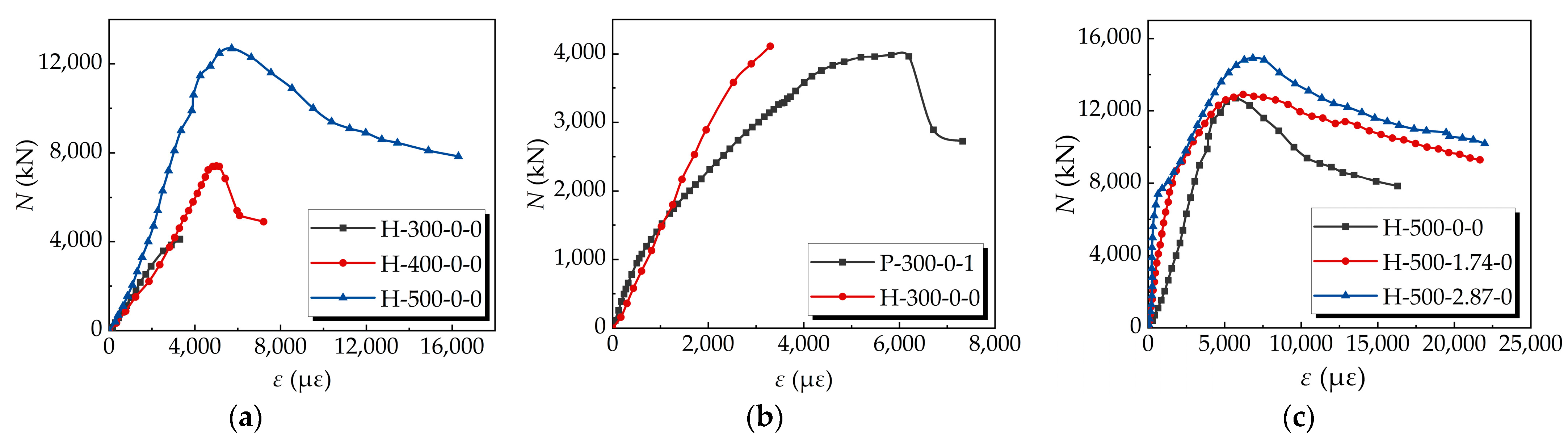
The relationship between the axial load and vertical compression displacement, as measured during the loading process, is represented by an axial load (N)–nominal axial strain curve (ε), as illustrated in Figure 8.
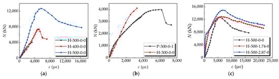
Figure 8.
Load–vertical strain curves. (a) Effect of the D0. (b) Effect of the tubular type. (c) Effect of the ρb.
It can be seen from Figure 8a that the axial compression response and failure mode of the specimens with different diameters are quite different. The ductility of specimen H-300-0-0 is the worst, and as its bearing capacity continues to rise, the lock seam of the HCST opens, and the core concrete loses the constraint of the HCST, leading to shear failure. The diameter-to-thickness ratio of specimen H-500-0-0 is greater than that of specimen H-400-0-0. However, because the helix angle of specimen H-500-0-0 is relatively small, its ductility is greatly improved compared to specimen H-400-0-0. Based on the above analysis, it can be inferred that due to the smaller helix angle, the HCST bears less of an axial load and can provide more hoop restraint.
It can be seen from Figure 8b that the peak strain of specimen H-300-0-0 is 3927 με, while that of specimen P300-0-1 is 5826 με. When the HCST adopts a larger helix angle and the other specimen parameters (diameter–thickness ratio, steel strength, concrete strength, etc.) are the same, its restraining effect on the core concrete is not as good as that of the plain straight steel tube.
Figure 8c demonstrates that the configuration of the longitudinal steel bars in the HCST leads to an improvement in both the bearing capacity and peak strain of the specimen. The increase in bearing capacity is proportional to the product of the area of the steel bar and its yield strength.
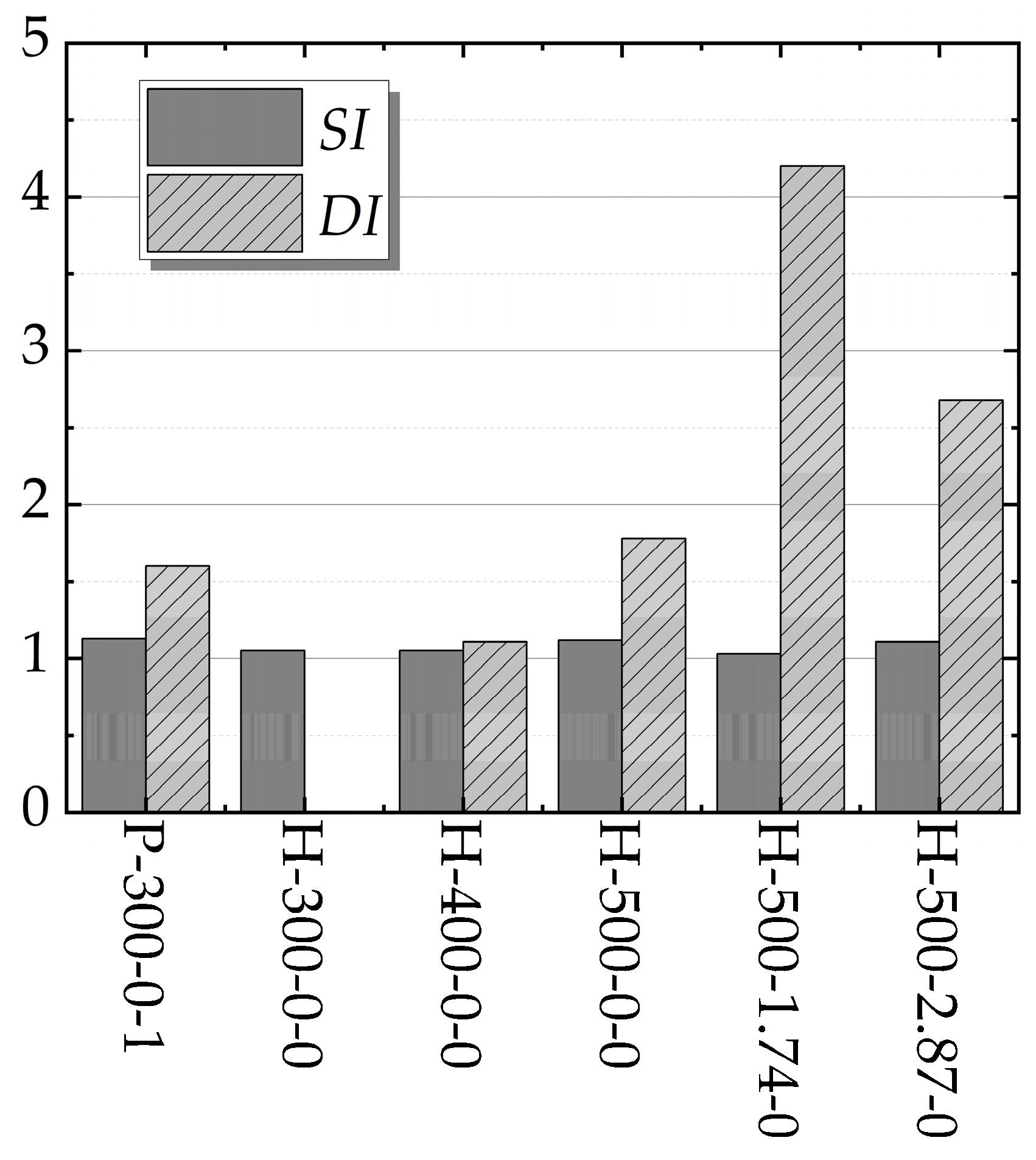
3.3. Strength Index and Ductility Index
The strength index, SI, is defined the beneficial effect on the ultimate load of the member induced by the confinement effect of the specimen [31,32], as follows:
where Nu is the test ultimate axial load and Nuc is the nominal ultimate axial load.
The ductility index, DI, can be used as an index with which to evaluate the deformability, which can be obtained using Equation (9) [6,33]:
where Δ85% is the corresponding displacement when the test ultimate load drops to 85%, Δy is the axial yield displacement, and the yield point is defined according to the method proposed by Park [34]. The axial load of specimen H-300-0-0 did not drop to the ultimate load of 85%. Therefore, its ductility factor was not calculated.
As shown in Figure 9, the strength and ductility index of specimen P-300-0-1 is similar to that of specimen H-500-0-0. Therefore, when the helix angle of the HCST is reduced, the CFHCST columns can achieve a combination effect similar to that of steel tube-reinforced concrete (STRC) columns. It should be noted that specimen H-500-0-0 has a steel ratio of 1.648% and a diameter of 500 mm, while specimen P-300-0-1 has a steel ratio of 2.477% and a diameter of 300 mm. If we consider the influence of the steel ratio and concrete size effect, it can be qualitatively judged that the confinement effect of an HCST with a helix angle of 21° on core concrete is slightly better than that of circular steel tubes with the same parameters. The peak strain of the CFHCSTs increases gradually with the increase in the volumetric steel ratios of the longitudinal reinforcement. However, the strength index of the specimens remains basically unchanged. After configuring an appropriate amount of longitudinal reinforcements in the CFHCST, the ductility of the composite columns can be significantly improved.

Figure 9.
Strength index and ductility index.
4. Working Mechanism
4.1. Transverse Deformation Coefficient
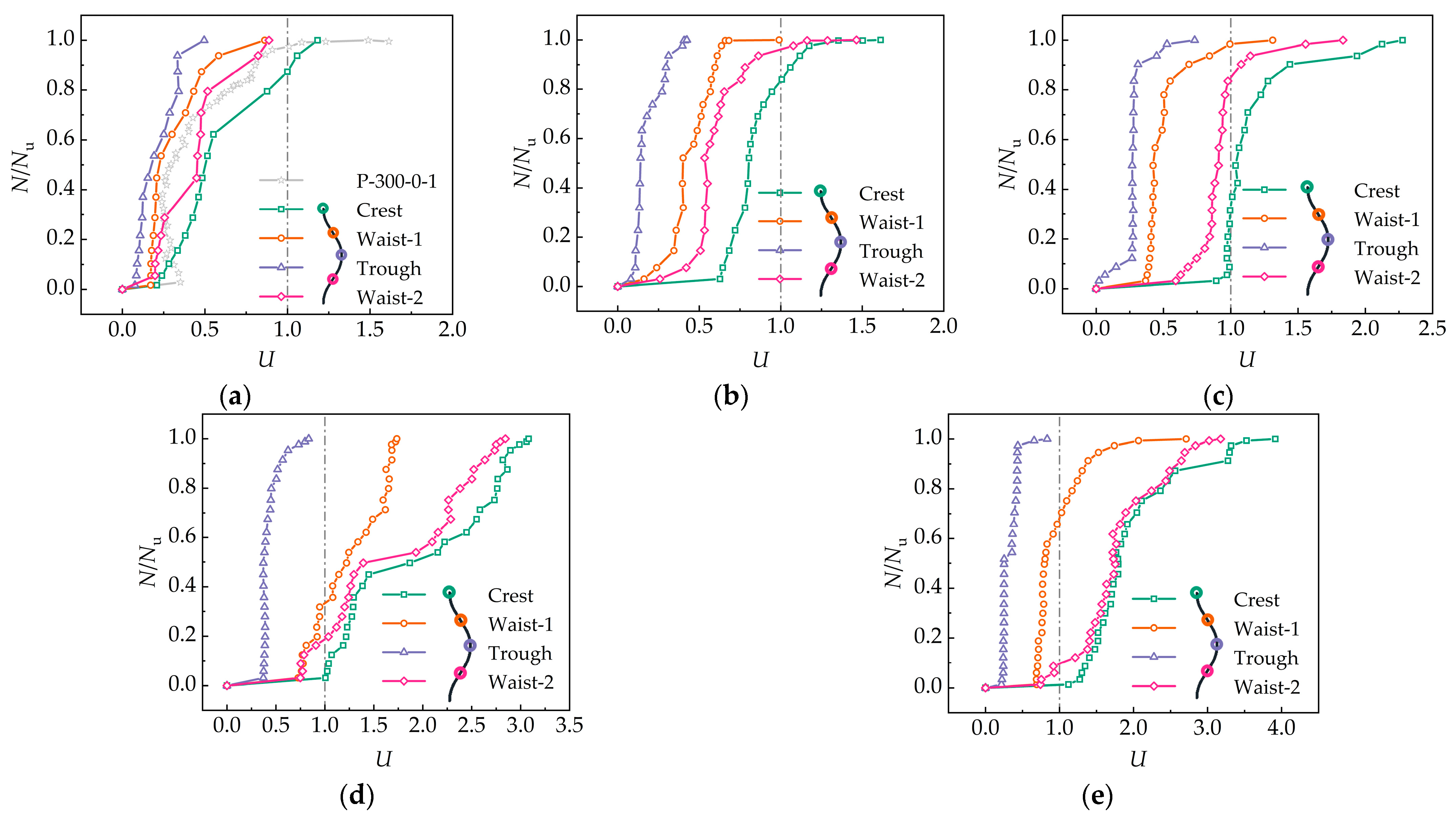
The transverse deformation coefficient is used to express the confining effect of the steel tube on the core concrete. The strength and diameter of the crests, troughs, and middle of the HCSTs are different. The restraint effect is also quite different. The transverse deformation coefficient, U, is calculated using Equation (10):
where εh is the hoop strain of the steel tube and εv is the vertical strain of the steel tube. All the strain data were measured using resistance strain gauges attached to the surface of the steel tube.
In Figure 10a, the relationship between the normalized load and the transverse deformation coefficient of plain straight steel tubes and HCSTs at different positions is depicted.
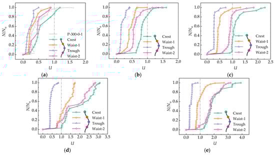
Figure 10.
Normalized load and transverse deformation coefficient curve. (a) P-300-0-1 and H-300-0-0. (b) H-400-0-0. (c) H-500-0-0. (d) H-500-1.74-0. (e) H-500-2.87-0.
Specimen P-300-0-1 was in the elastic stage before reaching 0.6 times the peak load, and the deformation of the steel tube was mainly influenced by the vertical force. After surpassing 0.6 times the peak load, the specimen entered the elastic–plastic development stage, and its lateral expansion accelerated, leading to an increase in the transverse deformation coefficient of the steel tube. As the specimen approached its peak load, the transverse deformation coefficient reached approximately one, indicating that the steel tube’s deformation was dominated by transverse expansion. The steel tube primarily provided restraint to the core concrete, but due to friction and bonding between the steel tube and the concrete, the inside of the steel tube still experienced significant vertical force.
There were notable differences in the transverse expansion at different positions of the HCST. The crest exhibited the most effective hoop confinement, while the trough had the least effect. Comparing specimens H-300-0-0, H-400-0-0, and H-500-0-0 (Figure 10a–c), reducing the helix angle increased the transverse deformation coefficient at each position of the HCST. This indicates that decreasing the helix angle enhances the HCST’s ability to provide circumferential constraint to the core concrete. For example, at peak loads, the transverse deformation coefficients at the peaks for specimens H-300-0-0, H-400-0-0, and H-500-0-0 were 1.18, 1.61, and 2.27, respectively. Similarly, the transverse deformation coefficients of waist-1 and waist-2 significantly increased as the helix angle decreased. The transverse deformation coefficient at the trough also increased with decreasing helix angle, but it remained less than one, indicating that the force at the trough was primarily vertical compression.
In the comparative specimens H-500-0-0, H-500-1.74-0, and H-500-2.87-0 (Figure 10c–e), as the volumetric steel ratios of the longitudinal reinforcement increased, the transverse deformation coefficient at peak load also gradually increased for each specimen. When combined with the load–vertical strain data, it can be observed that the peak strain of each specimen also increased with higher volumetric steel ratios of the longitudinal reinforcement. This implies that HCSTs need to provide greater hoop restraint to effectively confine the core concrete as the volumetric steel ratios of the longitudinal reinforcement increase.
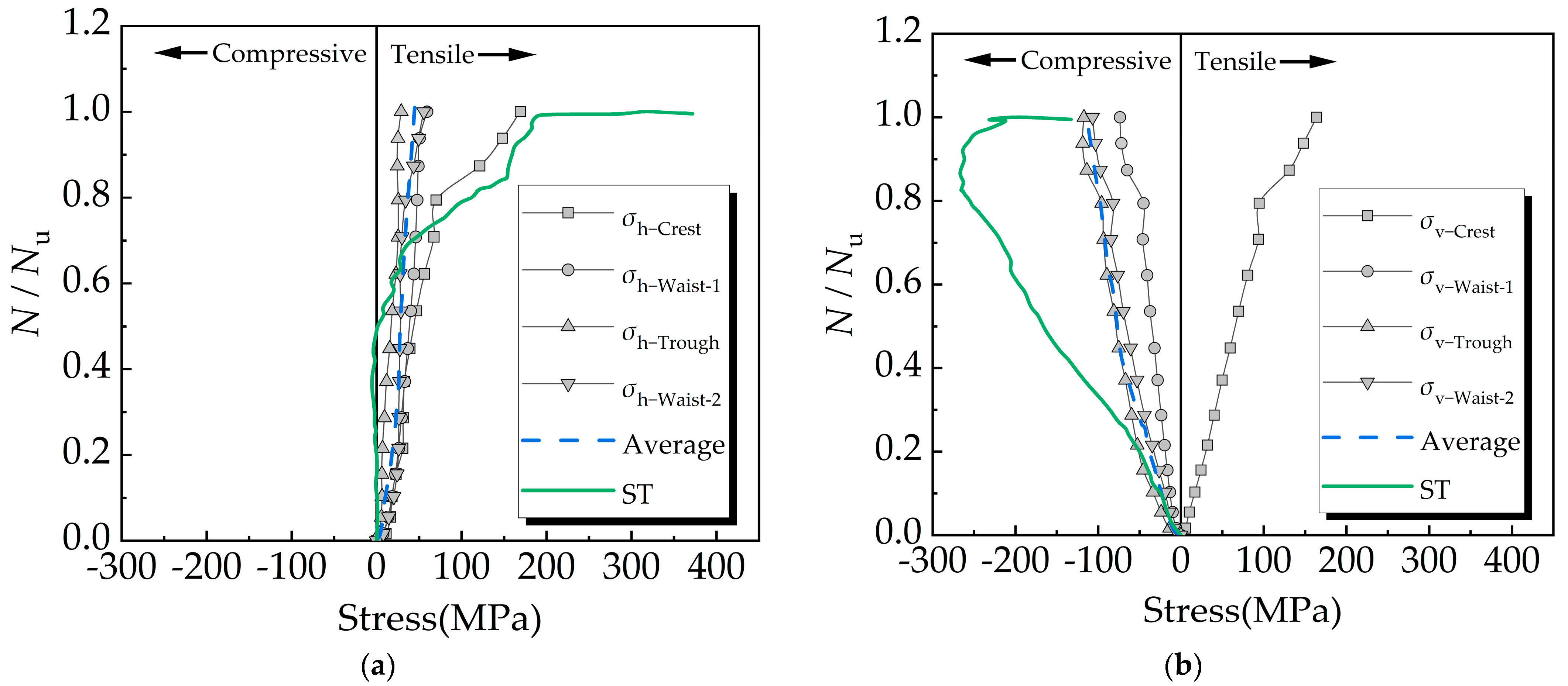
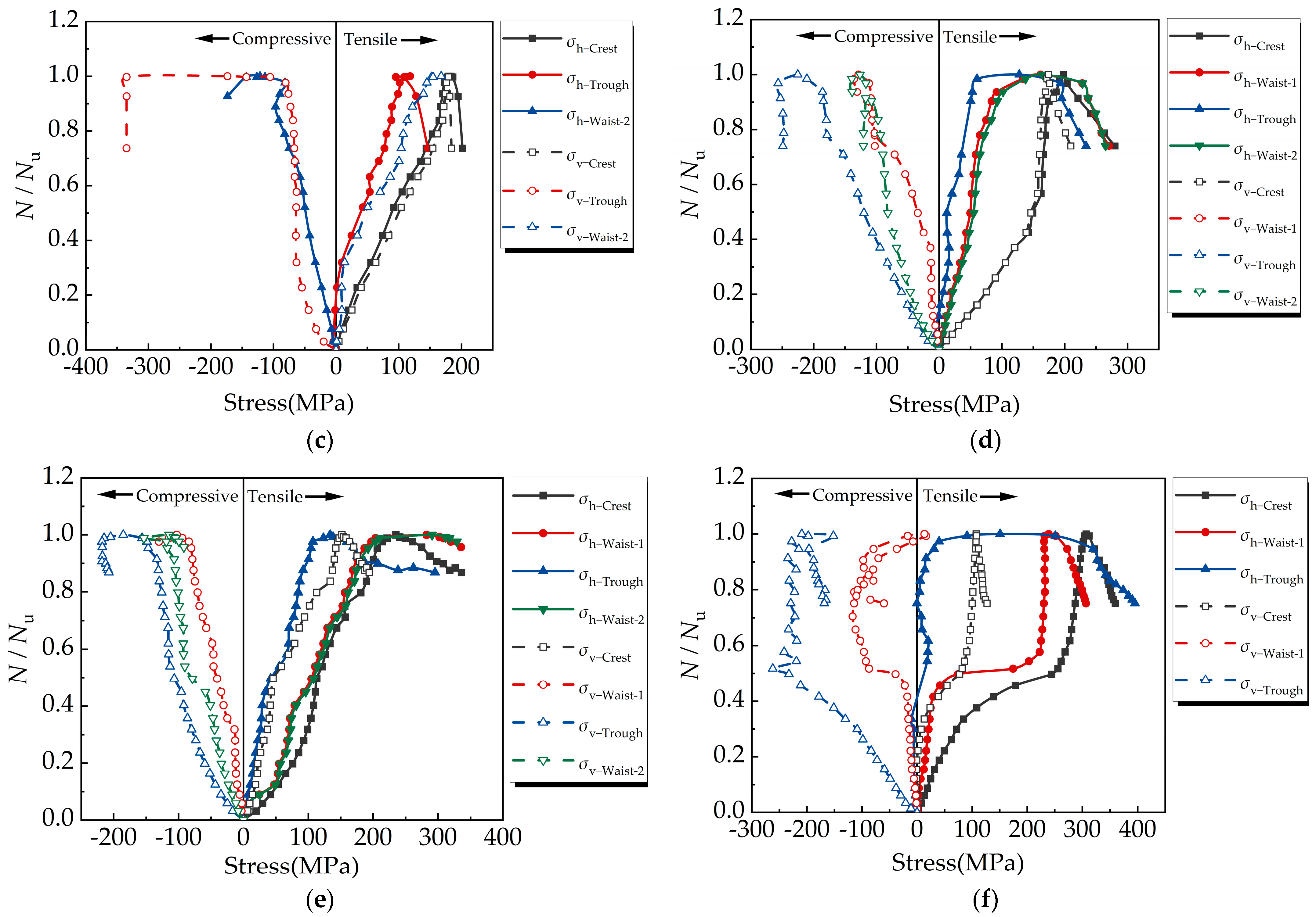
4.2. Steel Tube Stress Analysis
Based on the hoop strain and vertical strain data for the steel tube, this paper uses the peeling analysis method and the steel constitutive relationship in the plane stress state to obtain the steel tube stress [6,7]. The corrugated form of the HCST results in a certain angle between the longitudinal stress and the vertical stress at the middle-1 and middle-2 sections. The angles for the HCSTs are 27°, respectively. When conducting a peeling analysis on these sections, the influence of the corrugation angle on the vertical stress and hoop stress is considered.
Different types of steel tubes have distinct effects on steel tube stress (Figure 11a,b). During the initial loading stage of specimen P-300-0-1, due to friction and bonding between the concrete and steel tube, the steel tube experiences significant vertical stress, while the hoop stress increases slowly. As loading continues, the steel tube begins to act as a hoop constraint on the core concrete, and the hoop stress increases. When the steel tube reaches yield strength, the load of the specimen no longer increases, but the axial displacement continues to increase. The failure of the steel tube to provide stronger restraint leads to specimen failure.
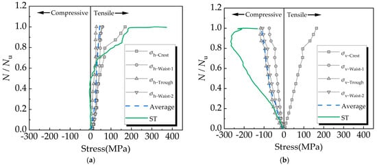
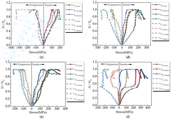
Figure 11.
Comparison of hoop stress and vertical stress of steel tubes. (a) Comparison of hoop stress between ST and HCST. (b) Comparison of vertical stress between ST and HCST. (c) H-400-0-0. (d) H-500-0-0. (e) H-500-1.74-0. (f) H-500-2.87-0.
Comparing specimens H-300-0-0, H-400-0-0, and H-500-0-0 (Figure 11a–d), it can be concluded that the CST stress modes are similar, but as the helix angle decreases, the hoop stress provided by each part of the CST increases when the peak load is reached. Comparing specimens H-500-0-0, H-500-1.74-0, and H-500-2.87-0 (Figure 11d–f), it can be concluded that with an increase in the longitudinal reinforcement ratio, the hoop stress of each part of the CST increases when the specimen reaches peak load, and the hoop restraint force at the trough and waist increases more significantly.
Due to the CST’s unique profile, the steel in each part of the CST is in a different stress state. The steel at the crest is under tension in both directions, while the steel at the trough and waist are in a state of hoop tension and axial compression. During the loading process of the CFHCST, the steel at the crest yields first. However, the steel at the trough and waist has not yielded yet, so the trough and waist can provide greater hoop restraint stress, allowing the CFHCST column to continue bearing. When the steel at the trough and waist reaches yield strength, the restraint force provided by the CST no longer increases, leading to the eventual failure of the composite column with increasing axial displacement. Compared to flat steel tubes, the hoop stress in the CST begins to increase during the initial loading stage, enabling the CST to maintain its restraint effect on the concrete core throughout the loading process. Additionally, the steel materials in the different parts of the CST can yield sequentially, allowing the full exertion of the CST’s strength and ductility.
4.3. Prediction of Shear Direction of Concrete Core in CST
The shear angle of the concrete core can be predicted when the concrete core is subjected to shearing and damage under the axial load of both CFST columns and STRC columns [35,36]. However, predicting the shear direction of the CFST core is generally challenging, due to the heterogeneity and nonlinear characteristics of concrete. The concrete core shear for each specimen is summarized in Figure 12. It can be observed that the shear direction of the CFST core deviates from the helical direction of the outer CST.
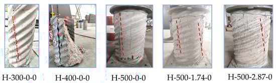
Figure 12.
Concrete core shear direction of CFCST columns.
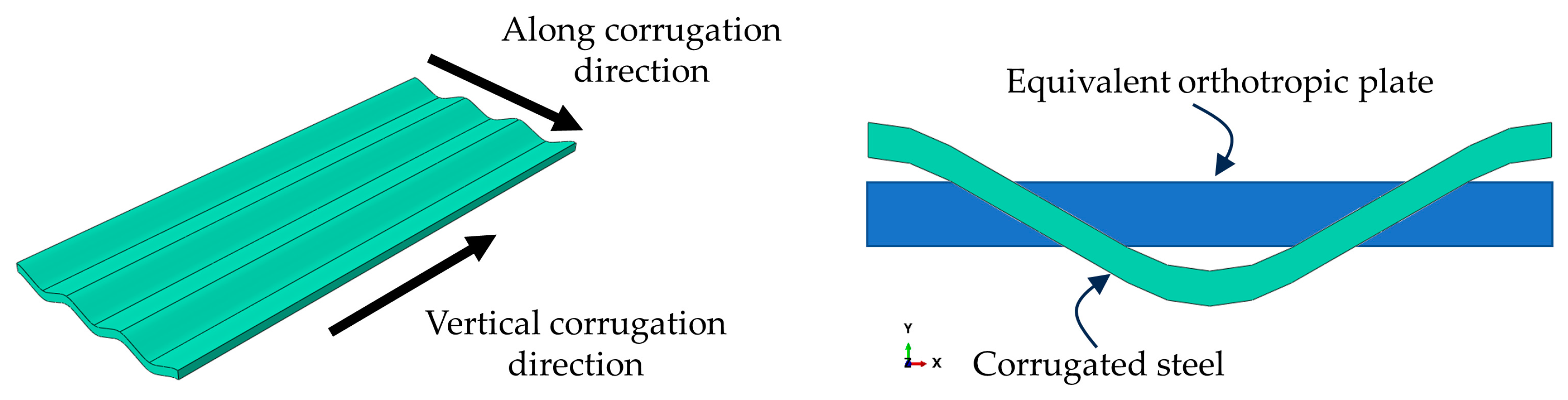
The consistent shear direction of the concrete core in the CFCST column is closely related to the inherent characteristics of the CST. One of the main characteristics of corrugated steel structures is their anisotropic mechanical behavior. The stiffness of corrugated steel perpendicular to the corrugation direction is approximately 10–50 times greater than that along the corrugation direction [37,38,39]. To analyze corrugated steel structures, Tamer Mohamed [40] proposed a calculation method that treats corrugated steel plates as three-dimensional orthotropic plates (refer to Figure 13).

Figure 13.
Equivalent schematic diagram for corrugated steel.
The principles of equivalence for this calculation method are as follows:
- (1)
- Bending, tensile, and compressive equivalents perpendicular to the corrugation direction;
- (2)
- Bending, tensile and compressive equivalents along the corrugation direction.
The calculation formulas are presented in Equations (11)–(15):
where h is the corrugation height, l is half the corrugation length, t is the corrugation thickness, Es is the elastic modulus of steel, Eθ is the equivalent elastic modulus of steel perpendicular to the direction of corrugation, Ez is the equivalent elastic modulus of steel along the corrugation direction, G is the shear modulus of steel, is the equivalent shear modulus of steel in local coordinates 1–2 and 1–3, and is the equivalent shear modulus of steel in local coordinates 2–3.
In this paper, the corrugated steel plate is considered as a three-dimensional orthotropic plate, and the CST is analyzed as an orthotropic plate. The corrugated profile used in the test has dimensions of 68 × 13 mm, and the steel plate has a thickness of 2 mm. According to Equations (11)–(15), the equivalent shear modulus perpendicular to the corrugation direction is 8508.29 MPa, while the shear modulus along the corrugation direction is only 337.97 MPa. The shear modulus ratio of the CST in two directions is 25.17.
It is evident that after the corrugated steel plate with dimensions of 68 × 13 mm and a thickness of 2 mm is transformed into a CST, the shear stiffness of the CST along the corrugation direction is lower than that perpendicular to the corrugation direction. Consequently, under an axial compression load, the shear failure of the concrete core is more likely to occur in this direction. The shear direction of the CST concrete composite column can also be predicted, and the damage mode of the CFCST column under an axial load develops perpendicularly to the helical direction of the CST.
5. Ultimate Load-Bearing Capacity
5.1. Comparison with Design Codes
This section focuses on the calculation of the ultimate strength of the tested columns based on the design codes JGJT 471-2019 [41], GB50936-2014 [42], and Eurocode 4 [43]. The calculated results were then compared to the experimental results to study the applicability of design calculation formulas for CFST specimens when calculating the axial compressive bearing capacity of concrete-filled helical corrugated steel tubes (CFHCSTs) and thin-walled steel tubes.
Table 3 presents a comparison between the ultimate bearing capacity of the test specimens and the calculated ultimate bearing capacity of each specification.
Table 3.
Comparison of test results with codes for bearing capacity calculations.
According to the analysis, JGJT 471-2019 overestimates the ultimate bearing capacity of CFCST columns with large helix angles (such as H-300-0-0) because the calculation method is based on the angle, whereas the steel tube only provides hoop stress. However, a large helix angle causes the steel tube to transmit more longitudinal stress. On the other hand, GB50936-2014 and Eurocode 4 underestimate the ultimate bearing capacity of CFCST columns with small helix angles (such as H-500-2.87-0), because a CST with a small helix angle mainly provides hoop constraints, and the longitudinal stress of the CST is very small.
Therefore, it is necessary to establish a calculation method for the axial compression ultimate bearing capacity of CFCST columns that takes into account the characteristics of CSTs, such as helix angle and corrugation profile.
5.2. Revised Formula for Compressive Capacity
5.2.1. Proposition of Calculation Formula
This study proposes a calculation method for the ultimate axial compression bearing capacity that considers the characteristics of CSTs. The calculation method ignores the axial bearing capacity of the CST and considers the core concrete effect of the CST restraint, referring to the formula form of JGJT 471-2019 [41]. The ultimate axial pressure bearing capacity can be calculated using Equation (16):
where fcc is the design value of the concrete axial compressive strength considering the lateral restraint, fcd is the design value of the concrete axial compressive strength, Ab is the area of the longitudinal steel bars in the composite column, Ac is the area of the concrete in the composite column, fyr is the yield strength of the longitudinal steel bars in the composite column, and fel is the equivalent restraint stress of the helical corrugated steel tube.
The calculation method for fel is shown in Equations (18) and (19):
where kc is the corrugated factor; fyt is the yield strength of the CST; and A, B, and C are all undetermined parameters. The fitting can be performed based on the previous experimental data. After the fitting of the experimental data in this study, A is 0.6, B is 3, and C is 0.2.
The proposed calculation method for the CFCST axial compression bearing capacity takes into account the important characteristics of CSTs, such as their corrugated profile and helix angle. This calculation method is based on the concept and form of the steel tube-confined concrete columns, and can also be applied to predict the axial compression bearing capacity of straight steel tube-confined concrete columns.
5.2.2. Verification of Calculation Formula
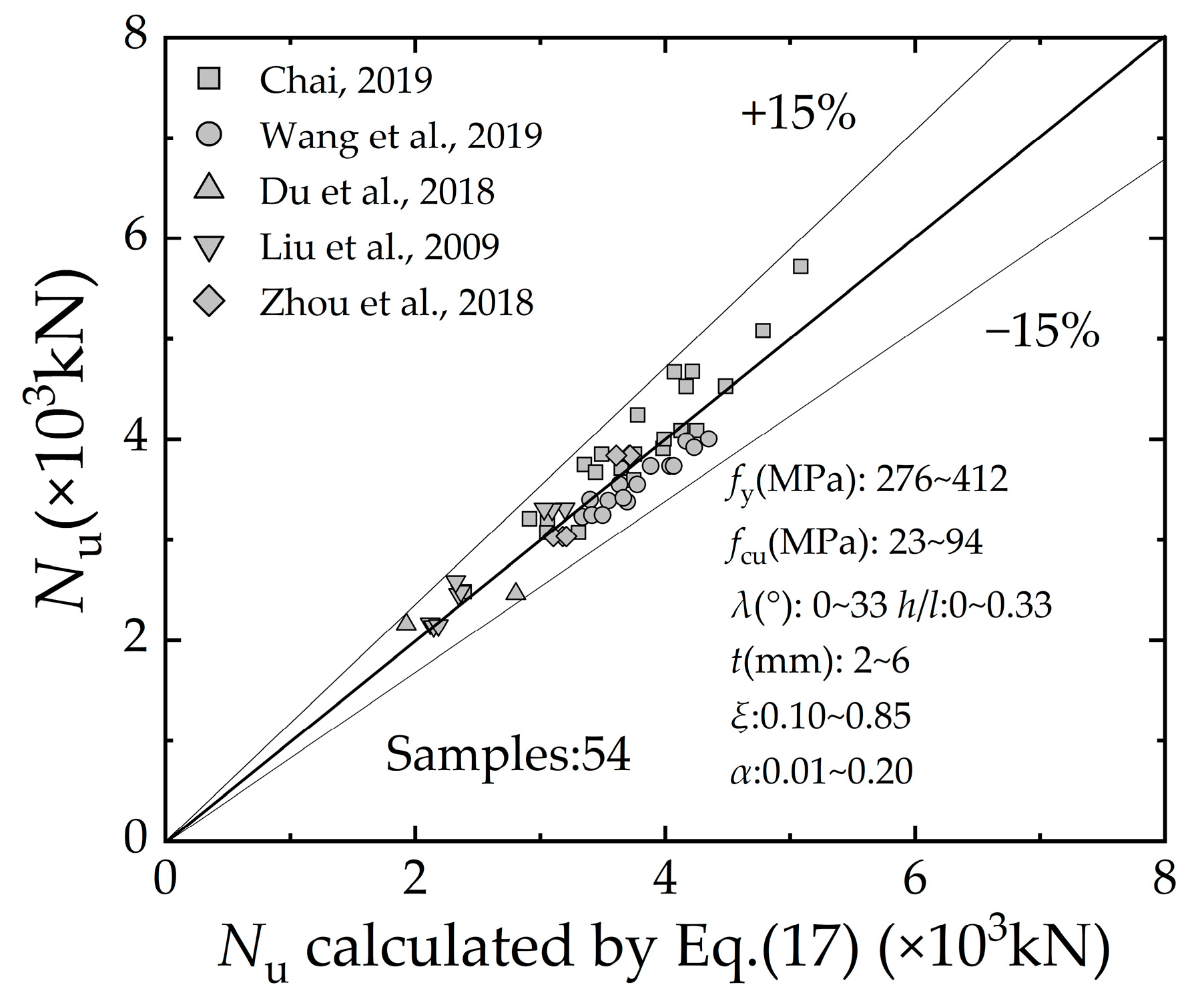
To verify the formula proposed in the previous section, relevant specimens from the published literature were collected [8,44,45,46,47]. The sample type for data collection should be an STRC column or CFCST column. Figure 14 shows that the collected specimen parameters are relatively diverse. The selected specimen samples cover a wide range of areas. Using the 54 collected STRC/CFCST specimens as samples, the ultimate bearing capacity formula proposed in this article was used to predict the bearing capacity. The calculated results were then compared to the axial compression bearing capacity obtained from the test, and the error analysis is shown in Figure 14.
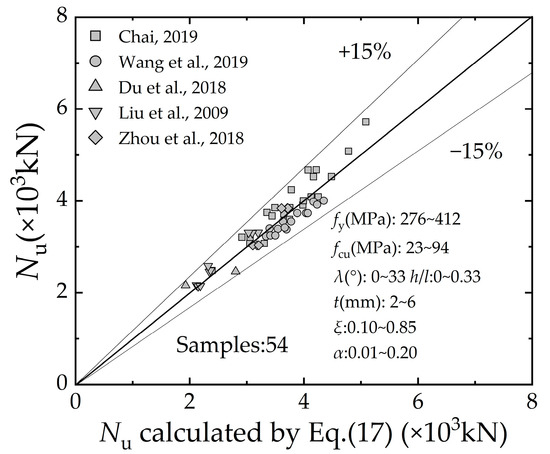
Figure 14.
Comparison of Equation (17) and the tests results [8,44,45,46,47].
Figure 14 shows that, the error between the calculated bearing capacity and the tested ultimate bearing capacity of the all specimens is less than 15%, indicating a high level of accuracy. In summary, the proposed calculation method can more accurately predict the ultimate axial compression bearing capacity of STRC columns and CFCST columns.
6. Summary and Conclusions
This paper presents an experimental study on the axial compression performance of CFHCST columns. The primary test variables are as follows: (a) The inner diameter of the column and the resulting geometrical changes in the HCST. (b) The volumetric steel ratios of the longitudinal reinforcement. The failure modes, load–vertical strain curves, strength index and ductility index, transverse deformation properties, and stress characteristics of the specimens are evaluated and discussed. Finally, a formula for calculating the axial compression bearing capacity of the STRC and CFCST is proposed. Based on the research results, the following conclusions can be drawn:
- (1)
- Lock seam slip and tear failure is a typical failure mode of the HCST. The lock seam strength and helical angle are key factors that affect the axial compression performance and the failure mode of the CFHCST columns. CFHCST columns with a helix angle of 33° exhibit a brittle failure mode with open lock seams, while those with a helix angle not greater than 26° exhibit a better ductile failure mode.
- (2)
- Under an axial compression load, the HCST closely engages with the core concrete, resulting in coordinated deformation. Compared to plain steel tubes, HCSTs provide greater circumferential restraint to the core concrete, and transfer only a portion of the longitudinal stress. This circumferential restraint offered by HCSTs effectively limits the shear deformation of and crack development in the core concrete. Consequently, the failure mode of the composite components becomes more predictable and controllable.
- (3)
- The axial compression load transmission mechanism of the CFHCST composite members: The transmission of longitudinal stress in an HCST is blocked at the crest, resulting in less longitudinal force being borne by the HCST across the entire section. Instead, under the joint action of the “vertical deformation effect” and the “circular tightening effect,” the HCST provides greater circumferential restraint for the core concrete. This circumferential confinement exhibits alternating strong and weak discontinuities along the corrugation direction.
- (4)
- According to the JGJT 471-2019 specifications, a prediction formula for the ultimate load-bearing capacity of CFHCST columns under axial compression is proposed. This formula takes into account the strong restraining effect of HCSTs on the core concrete, as well as the characteristics of HCSTs, such as their corrugated profile and helical angle. The accuracy of this formula is verified using specimens from other researchers. It has been found that this formula provides better predictions for the axial compression ultimate bearing capacity of both steel tube-confined concrete components and CFHCST components.
The CFHCST columns utilized in this study provide valuable insights; however, limitations stem from the restricted number of specimens. Future research endeavors should consider larger and more diverse samples to validate and generalize the conclusions. Additionally, exploring variations in loading conditions and specimen parameters could offer a more comprehensive understanding of the studied CFHCST columns.
Author Contributions
Conceptualization, H.S.; methodology, H.S.; software, L.Z.; formal analysis, H.S. and M.F.; investigation, H.S. and M.F.; resources, H.S.; data curation, Y.L.; writing—original draft, H.S. and L.Z.; writing—review and editing, L.Z. and B.L.; project administration, B.L.; funding acquisition, H.S. and B.L. All authors have read and agreed to the published version of the manuscript.
Funding
This research was funded by the National Nature Science Foundation of China (No. 51478030) and the Qilu Transportation Technology Project (No. KJ-2019-QLJTJT-01).
Data Availability Statement
The data presented in this study are available on request from the corresponding author. The data are not publicly available due to research is continuing.
Conflicts of Interest
Author Haibo Sun was employed by the company Shandong Provincial Transportation Planning and Design Institute Company Ltd. Author Mingyang Feng was employed by the company China Construction Eighth Engineering Division Co., Ltd. The remaining authors declare that the research was conducted in the absence of any commercial or financial relationships that could be construed as a potential conflict of interest.
Nomenclature
| λ | corrugation angle, in ° |
| l | corrugation length, in mm |
| h | corrugation height, in mm |
| Din | inner diameter, in mm |
| Dout | outer diameter, in mm |
| D0 | nominal diameter, in mm |
| t | steel tube thickness, in mm |
| L | short column length, in mm |
| ρb and ρs | volumetric steel ratio of longitudinal and transverse steel bars, in % |
| α | steel ratio of steel tube, in % |
| ξ | confinement index |
| Nu | peak load or ultimate load-bearing capacity, in kN |
| εu | member deformation at peak load, in με |
| SI | strength index |
| DI | ductility index |
| B | width of the strip, in mm |
| ηc | corrugated amplification factor |
| ws | length of one period of corrugation, in mm |
| As and Ac | cross-sectional areas of the steel tube and core concrete, in mm2 |
| fy | average yield strength of the steel tube, in MPa |
| fcp | average prism compressive strength of concrete, in MPa |
| Es and Ec | elastic modulus of steel and concrete, in MPa |
| fy-crest, fy-waist, and fy-trough | yield strengths of crest, waist, and trough, respectively, in MPa |
| λcrest, λwaist, and λtrough | ratios of each position to a complete corrugation |
| Nu | test ultimate axial load, in kN |
| Nuc | nominal ultimate axial load, in kN |
| Δ85% | corresponding displacement when the test ultimate load drops to 85%, in mm |
| Δy | axial yield displacement, in mm |
| U | transverse deformation coefficient |
| εh | hoop strain of the steel tube, in με |
| εv | vertical strain of the steel tube, in με |
| Eθ | equivalent elastic modulus of steel perpendicular to the direction of corrugation, in MPa |
| Ez | equivalent elastic modulus of steel along corrugation direction, in MPa |
| G | shear modulus of steel, in MPa |
| equivalent shear modulus of steel in local coordinates 1–2 and 1–3, in MPa | |
| equivalent shear modulus of steel in local coordinates 2–3, in MPa | |
| fcc | design value of concrete axial compressive strength considering lateral restraint, in MPa |
| fcd | design value of concrete axial compressive strength, in MPa |
| Ab | area of longitudinal steel bars in the composite column, in mm2 |
| Ac | area of concrete in the composite column, in mm2 |
| fyr | yield strength of the longitudinal steel bars in the composite column, in MPa |
| fel | equivalent restraint stress of helical corrugated steel tube, in MPa |
| kc | corrugated factor |
| fyt | yield strength of CST, in MPa |
| A, B, and C | undetermined parameters |
References
- Cao, X.; Xie, X.D.; Zhang, T.Y.; Du, G.F. Bond-slip behavior between high-strength steel tube and Ultra-high Performance Concrete. Structures 2022, 47, 1498–1510. [Google Scholar] [CrossRef]
- Yu, P.; Ren, Z.Y.; Yun, W.J.; Zhao, Y.; Xu, J.L. Performance of Bolt-Welded CFST Short Columns with Different Initial Imperfections: Experimental and Numerical Studies. Buildings 2022, 12, 1352. [Google Scholar] [CrossRef]
- Hassan, M.M.; Mahmoud, A.A.; Serror, M.H. Behavior of concrete-filled double skin steel tube beam-columns. Steel Compos. Struct. 2016, 22, 1141–1162. [Google Scholar] [CrossRef]
- Han, L.H.; Ma, D.Y.; Zhou, K. Concrete-encased CFST structures: Behaviour and application. In Proceedings of the 12th International Conference on Advances in Steel-Concrete Composite Structures (ASCCS), Valencia, Spain, 27–29 June 2018; pp. 1–10. [Google Scholar]
- Zhao, D.; Zhang, J.G.; Lu, L.; Liang, H.Z.; Ma, Z.H. The Strength in Axial Compression of Aluminum Alloy Tube Confined Concrete Columns with a Circular Hollow Section: Experimental Results. Buildings 2022, 12, 699. [Google Scholar] [CrossRef]
- More, F.; Subramanian, S.S. Experimental Investigation on the Axial Compressive Behaviour of Cold-Formed Steel-Concrete Composite Columns Infilled with Various Types of Fibre-Reinforced Concrete. Buildings 2023, 13, 151. [Google Scholar] [CrossRef]
- Liu, B.D.; Zhang, L.L.; Feng, M.Y.; Sun, H.B.; Chai, Y.K. Experimental Study of Rubber-Concrete-Filled CST Composite Column Under Axial Compression. Int. J. Steel Struct. 2023, 23, 247–262. [Google Scholar] [CrossRef]
- Wang, Y.Y.; Yang, L.G.; Yang, H.; Liu, C.Y. Behaviour of concrete-filled corrugated steel tubes under axial compression. Eng. Struct. 2019, 183, 475–495. [Google Scholar] [CrossRef]
- Tang, Z.J.; Hong, S.K.; Xiao, W.Z.; Taylor, J. Characteristics of iron corrosion scales established under blending of ground, surface, and saline waters and their impacts on iron release in the pipe distribution system. Corros. Sci. 2006, 48, 322–342. [Google Scholar] [CrossRef]
- Chen, T.L.; Su, M.Z.; Pan, C.L.; Zhang, L.; Wang, H.M. Local buckling of corrugated steel plates in buried structures. Thin-Walled Struct. 2019, 144, 11. [Google Scholar] [CrossRef]
- Biddah, A.; Ghobarah, A.; Aziz, T.S. Upgrading of nonductile reinforced concrete frame connections. J. Struct. Eng. ASCE 1997, 123, 1001–1010. [Google Scholar] [CrossRef]
- Ghobarah, A.; Biddah, A.; Mahgoub, M. Rehabilitation of reinforced concrete columns using corrugated steel jacketing. J. Earthq. Eng. 1997, 1, 651–673. [Google Scholar] [CrossRef]
- Liu, B.D.; Zhang, L.L.; Sun, H.B.; Feng, M.Y.; Dou, K.J. Side shear strength and load-transfer mechanism of corrugated steel column-foundation socket connection. Case Stud. Constr. Mater. 2022, 17, 22. [Google Scholar] [CrossRef]
- Su, R.; Li, X.; Zhong, T.; Zhou, T. Axial behavior of novel CFDST columns with outer welded corrugated steel tubes. Structures 2021, 34, 2708–2720. [Google Scholar] [CrossRef]
- Fang, Y.; Liu, C.Y.; Yang, H.; Yang, L.G. Axial behaviour of concrete-filled corrugated steel tubular column embedded with structural steel. J. Constr. Steel Res. 2020, 170, 29. [Google Scholar] [CrossRef]
- Yang, L.G.; Wang, Y.Y.; Elchalakani, M.; Fang, Y. Experimental behavior of concrete-filled corrugated steel tubular short columns under eccentric compression and non-uniform confinement. Eng. Struct. 2020, 220, 22. [Google Scholar] [CrossRef]
- Fang, Y.; Wang, Y.; Yang, H.; Lin, X. Experimental behavior of concrete-filled thin-walled corrugated steel tubes with large helical angles under monotonic and cyclic axial compression. Thin-Walled Struct. 2022, 173, 109043. [Google Scholar] [CrossRef]
- Xiao, X.H.; Bu, G.B.; Ou, Z.H.; Li, Z.C. Nonlinear in-plane instability of the confined FGP arches with nanocomposites reinforcement under radially-directed uniform pressure. Eng. Struct. 2022, 252, 12. [Google Scholar] [CrossRef]
- Xiao, X.H.; Zhang, Q.; Zheng, J.X.; Li, Z.C. Analytical model for the nonlinear buckling responses of the confined polyhedral FGP-GPLs lining subjected to crown point loading. Eng. Struct. 2023, 282, 13. [Google Scholar] [CrossRef]
- Li, Z.C.; Zhang, Q.; Shen, H.; Xiao, X.H.; Kuai, H.D.; Zheng, J.X. Buckling performance of the encased functionally graded porous composite liner with polyhedral shapes reinforced by graphene platelets under external pressure. Thin-Walled Struct. 2023, 183, 11. [Google Scholar] [CrossRef]
- Zhang, Q.; Li, Z.C.; Huang, H.; Zhang, H.P.; Zheng, H.; Kuai, H.D. Stability of submarine bi-material pipeline-liner system with novel polyhedral composites subjected to thermal and mechanical loading fields. Mar. Struct. 2023, 90, 12. [Google Scholar] [CrossRef]
- Chang, G.; Zhang, Q.; Li, Y.; Li, Z. Analytical and numerical buckling of bi-material pipelines reinforced by novel composite polyhedral linings. Appl. Ocean. Res. 2023, 141, 103799. [Google Scholar] [CrossRef]
- Fang, Y.; Wang, Y.; Hou, C.; Lu, B. CFDST stub columns with galvanized corrugated steel tubes: Concept and axial behaviour. Thin-Walled Struct. 2020, 157, 107116. [Google Scholar] [CrossRef]
- Fang, Y.; Wang, Y.Y.; Zhang, B.; Dong, J.C. Behaviour of concrete-filled thin-walled corrugated steel tubes under cyclic axial compression. Thin-Walled Struct. 2021, 162, 24. [Google Scholar] [CrossRef]
- Han, L.H.; Zhao, X.L.; Tao, Z. Tests and mechanics model for concrete-filled SHS stub columns, columns and beam-columns. Steel Compos. Struct. 2001, 1, 51–74. [Google Scholar] [CrossRef]
- GB. 50010-2010; Code for Design of Concrete Structures. Standards Press of China: Beijing, China, 2010.
- GB/T 34567-2017; Cold-Formed Corrugated Steel Pipes. China Standard Press: Beijing, China, 2017.
- GB/T 228-2010; Metallic Materials-Tensile Testing—Part 1: Method of Test at Room Temperature. Standards Press of China: Beijing, China, 2010.
- GB/T 50081-2002; Standard for Test Method of Mechanical Properties on Ordinary Concrete. China Architecture and Building Press: Beijing, China, 2002.
- G.B. 1499.2-2018; Steel for the Reinforcement of Concrete—Part 2: Hot Rolled Ribbed Bars. Standards Press of China: Beijing, China, 2010.
- Wang, Y.Y.; Chen, J.; Geng, Y. Testing and analysis of axially loaded normal-strength recycled aggregate concrete filled steel tubular stub columns. Eng. Struct. 2015, 86, 192–212. [Google Scholar] [CrossRef]
- Yang, Y.F.; Han, L.H. Compressive and flexural behaviour of recycled aggregate concrete filled steel tubes (RACFST) under short-term loadings. Steel Compos. Struct. 2006, 6, 257–284. [Google Scholar] [CrossRef]
- Feng, M.Y.; Liu, B.D.; Zhang, L.L.; Wang, Y.Y.; Sun, H.B. Seismic behavior of embedded rubberized concrete-filled corrugated steel tube column-to-foundation connections: Experimental, numerical modelling, and design. Soil Dyn. Earthq. Eng. 2024, 176, 16. [Google Scholar] [CrossRef]
- Park, R. Evaluation of ductility of structures and structural assemblages from laboratory testing. Bull. N. Z. Soc. Earthq. Eng. 1989, 22, 155–166. [Google Scholar] [CrossRef]
- Zhou, M.; Xu, L.Y.; Tao, M.X.; Fan, J.S.; Hajjar, J.F.; Nie, J.G. Experimental study on confining-strengthening, confining-stiffening, and fractal cracking of circular concrete filled steel tubes under axial tension. Eng. Struct. 2017, 133, 186–199. [Google Scholar] [CrossRef]
- Uenaka, K. Concrete filled double skin square tubular stub columns subjected to compression load. Struct. Eng. Mech. 2021, 77, 745–751. [Google Scholar] [CrossRef]
- Ha, N.S.; Lu, G.X. Thin-walled corrugated structures: A review of crashworthiness designs and energy absorption characteristics. Thin-Walled Struct. 2020, 157, 40. [Google Scholar] [CrossRef]
- Dayyani, I.; Shaw, A.D.; Flores, E.L.S.; Friswell, M.I. The mechanics of composite corrugated structures: A review with applications in morphing aircraft. Compos. Struct. 2015, 133, 358–380. [Google Scholar] [CrossRef]
- Yokozeki, T.; Takeda, S.; Ogasawara, T.; Ishikawa, T. Mechanical properties of corrugated composites for candidate materials of flexible wing structures. Compos. Pt. A-Appl. Sci. Manuf. 2006, 37, 1578–1586. [Google Scholar] [CrossRef]
- Elshimi, T.M. Three-Dimensional Nonlinear Analysis of Deep-Corrugated Steel Culverts. Ph.D. Thesis, Queen’s University, Kingston, ON, Canada, 2011. [Google Scholar]
- JGJT 471-2019; Technical Standard for Steel Tube Confined Concrete Structures. China Standard Press: Beijing, China, 2019.
- GB50936-2014; Technical Code for Concrete Filled Steel Tubular Structure. China Standard Press: Beijing, China, 2014.
- Eurocode 4; Design of Composite Steel and Concrete Structure: Part 1-1: General Rules for Buildings. European Committee for Standardization: Brussels, Belgium, 2004.
- Chai, Y. Experimental Study on Mechanical Properties of Short Corrugated Steel Tube Filled with Rubberized Concrete under Axial Load; Beijing Jiaotong University: Beijing, China, 2019. [Google Scholar]
- Du, F.Z.; Pan, S.S.; Li, D.S. Damage evaluation and failure mechanism analysis of steel tube confined reinforced-concrete columns by acoustic emission technology. Lat. Am. J. Solids Struct. 2018, 15, 14. [Google Scholar] [CrossRef]
- Liu, J.P.; Zhang, S.M.; Zhang, X.D.; Guo, L.H. Behavior and strength of circular tube confined reinforced-concrete (CTRC) columns. J. Constr. Steel Res. 2009, 65, 1447–1458. [Google Scholar] [CrossRef]
- Zhou, X.; Yan, B.; Liu, J. Axial load behavior of circular tubed reinforced concrete columns with different length-to-diameter ratios. J. Build. Struct. 2018, 39, 11–21. [Google Scholar]

Disclaimer/Publisher’s Note: The statements, opinions and data contained in all publications are solely those of the individual author(s) and contributor(s) and not of MDPI and/or the editor(s). MDPI and/or the editor(s) disclaim responsibility for any injury to people or property resulting from any ideas, methods, instructions or products referred to in the content. |
© 2023 by the authors. Licensee MDPI, Basel, Switzerland. This article is an open access article distributed under the terms and conditions of the Creative Commons Attribution (CC BY) license (https://creativecommons.org/licenses/by/4.0/).