Abstract
The period ratio and the drift ratio are commonly used as plane regularity control indices for multi-story buildings. However, they fail to reasonably reflect the regularity of lateral force-resisting component configuration and deformation characteristics in non-rigid plate bent frame structures. This study focuses on the analysis of non-rigid single-span bent frames, examining the variation patterns of a suitable regularity index for non-rigid plate bent frame structures, referred to as the shear force lateral stiffness matching index, under various parameters. Additionally, it introduces indices to quantify the deformation response of non-rigid plate bent frame structures, providing a detailed analysis of the impact of factors such as eccentricity, torsional stiffness, and roof slab stiffness on the deformation characteristics of non-rigid plate bent frame structures and the shear force lateral stiffness matching index. The results show that the shear force lateral stiffness matching index can reflect the inconsistency in the horizontal displacement response of lateral force-resisting components caused by deformations in the roof slab. The proposed indices for torsional and bending deformations accurately quantify the roof slab’s deformation response, revealing the horizontal deformation characteristics of lateral force-resisting components in non-rigid frames. When eccentricity is present, the stiffness of the roof slab has a non-monotonic effect on the torsional component of the structural seismic response.
1. Introduction
Despite the relatively late development of long-span buildings, their innovative designs and superior performance have facilitated rapid growth, establishing them as a significant structural form in urban infrastructure with substantial potential for future applications [1,2]. Long-span buildings encompass various forms, among which non-rigid plate bent frame structures are widely utilized due to their flexibility and adaptability to different architectural and engineering demands [3]. With the increasing requirements for earthquake resistance, anti-seismic design has become an essential component in the development of non-rigid plate bent frame structures [4].
The criteria for determining structural regularity, controlling structural torsion, and implementing construction measures are critical aspects of anti-seismic design. The definition of torsional irregularity encompasses discriminative indicators for controlling structural torsion, primarily including the drift ratio (η) (maximum displacement at the floor end divided by the average displacement of the floor), eccentricity. UBC97 [5], NEHRP [6], IBC2003 [7], EC [8], NZS4203 [9], and the “Code for anti-seismic design of Buildings” [10] specify that when η > 1.2, the structure is considered irregular. NZS4203 stipulates that η > 1.4 defines an irregular structure, while Europe’s EC8 ensures plan regularity by controlling eccentricity. Furthermore, China’s “Technical Specification for Concrete Structures of Tall Buildings” [11] introduces requirements for maintaining the period ratio, defined as the ratio of the first mode period dominated by torsional motion (Tt) to the first mode period dominated by translational motion (T1). The specification uses both the drift ratio and the period ratio as dual control indicators for structural regularity. This dual requirement for controlling structural irregularities is unique to China and is not found in the codes of other countries.
Recent studies have investigated the effectiveness of control measures for planar regularity indicators such as the drift ratio and the period ratio. Xu et al. [12], based on seismic measurements of three multi-story buildings, demonstrated the necessity of controlling the period ratio in seismic design for high-rise buildings and suggested that the control method for the period ratio should be adjusted for unconventional structures. Cai et al. [13], through the analysis of high-rise concrete structures, pointed out that in some cases, the dual control measures of coupled period ratio and displacement ratio might no longer be reasonable. Liu et al. [14] proposed an algorithm for the period ratio under different eccentricities. Their results indicated that in some situations, the period ratio values may not correlate with the structural regularity, and the period ratio may decrease as eccentricity increases. Wei et al. [15] conducted a theoretical analysis of the physical significance and control objectives of the period ratio for high-rise structures. They pointed out that many factors influence the period ratio in high-rise structures, but only by increasing the torsional stiffness while maintaining translational stiffness can a reduction in the period ratio significantly improve the seismic performance of high-rise structures. Liu et al. [16] observed that in uneven-height ground structures, there is a significant inherent eccentricity in the shorter direction, which may lead to an increase in the relative eccentricity to meet the period ratio limit, thereby distorting the control of torsional effects. Wang et al. [17] noted that when a structure is vertically uniform or has minimal changes, the drift ratio can reflect the overall torsional effects of the structure; however, when there are significant vertical irregularities, especially at the top, the drift ratio may fail to reflect the overall torsional vibration effects of the structure accurately. Han et al. [18], based on a complex eccentric steel frame structure, proposed influencing parameters for the dynamic characteristics of single-layer biaxial eccentric structures. The analysis showed that as eccentricity increases, the torsional effects of the structure also increase; when the primary torsional frequency ratio approaches 1, the coupled translational–torsional effects are maximized, while the influence of the secondary torsional frequency ratio is relatively small.
Current research on torsional regularity indicators in seismic design primarily focuses on rigid roof panels, such as concrete roof panels, steel–concrete composite roof panels, and prestressed concrete roof panels. Previous research has already considered the impact of roof panel rigidity or its in-plane deformation on the structure. Jahami et al. [19] pointed out that shear reinforcement can effectively improve the stiffness and load-bearing capacity of post-tensioned prestressed concrete slabs under impact loads, thereby enhancing their impact resistance. Paul et al. [20] proposed a nonlinear elastoplastic finite element model to analyze the behavior of side panel connections and explored the effects of side panel thickness (in-plane stiffness), size, and spacing on connection stiffness. Sánchez et al. [21] proposed a numerical calculation method for the optimal design of planar semi-rigid steel frames, incorporating second-order effects to account for the influence of panel stiffness. He et al. [22] defined a horizontal load transfer coefficient to quantify the impact of in-plane stiffness on horizontal load distribution, explored the relationship between in-plane stiffness and the lateral stiffness ratio of vertical components and load transfer coefficients, and defined the concept of rigid floors based on lateral stiffness ratio and load transfer coefficients.
In fact, the rigidity or flexibility of the roof panel directly determines the distribution method of horizontal loads. The current studies on the impact of torsional regularity indicators in anti-seismic design are mostly based on multi-story structures, with very few studies focusing on non-rigid plate bent frame structures. Currently, the relevant codes [5,6,7,8,9,10,11,23,24] do not specify methods for evaluating the plane configuration regularity of non-rigid plate bent frame structures. In practical anti-seismic design, the methods and limit indices for calculating the regularity of non-rigid plate bent frame structures often apply indiscriminately to those used for multi-story buildings, such as the drift ratio and the period ratio. However, existing research indicates that due to the sparse configuration of lateral force-resisting components and relatively low in-plane stiffness of the roof slab in non-rigid plate bent frame structures, the drift ratio cannot accurately reflect the torsional effects and internal force response characteristics of structures [25,26]. Moreover, the period ratio limit specified in the “Technical Specification for Concrete Structures of Tall Buildings” is based on studies of non-coupled period ratios. However, non-rigid plate bent frame structures often exhibit coupling between translational and torsional modes. Research shows that the coupled period ratios may not accurately reflect the torsional characteristics of the structure [13,25]. Indiscriminately applying the regularity indices for multi-story buildings to non-rigid plate bent frame structures often results in cases where the lateral stiffness requirements are met, but the regularity indices exceed the limits [27,28,29].
In addition, the seismic response of horizontal components in non-rigid plate bent frame structures is minimal, so the focus should be on the lateral force-resisting components. These lateral force-resisting components not only provide lateral stiffness but also contribute significantly to torsional stiffness. The regularity in the arrangement of the lower support components in non-rigid plate structures affects not only the overall torsional effects but also the distribution of seismic responses in the lateral force-resisting components due to in-plane bending deformations, as non-rigid plate bent frame structures are not suitable for the rigid diaphragm assumption. Therefore, in the anti-seismic design of non-rigid plate bent frame structures, it is essential to focus on the calculation methods and control indicators of the regularity of the lateral force-resisting member layout.
Recent research has introduced a reasonable index, known as the shear force lateral stiffness matching index, for determining the regularity of lateral force-resisting component configurations in non-rigid plate bent frame structures [30]. The index can reflect the regularity of lateral force-resisting component configuration by describing the mismatch between the internal forces and the lateral stiffness of the components under seismic loading. It also considers the effects of roof slab bending deformations. Given that the seismic response of non-rigid plate bent frame structures is not significant, it is essential to pay greater attention to their lateral force-resisting components. The endpoints at the connections between these components and the roof panels are utilized to calculate the shear force lateral stiffness matching index and to extract the deformation characteristics of the roof panels.
This paper primarily focuses on the single-span, single-story frame structures commonly found in public buildings. Building on the dynamic characteristics of these structures and referencing [30], it further explores the properties and influencing factors of the shear force lateral stiffness matching index. Additionally, it proposes indices to quantify the roof slab deformation in non-rigid frame structures, providing references for the seismic conceptual design of long-span structures.
2. Definition of Plane Regularity Index
2.1. Shear Force Lateral Stiffness Matching Index
Ideally, a structure should experience only lateral movement during an earthquake. Under such conditions, the ratio of the shear force in the lateral force-resisting members to the total shear force of the structure equals the ratio of their lateral stiffness to the total stiffness. However, when the structure undergoes torsion, the lateral force-resisting members must bear not only the translational shear force but also the additional shear force caused by torsional effects, as shown in Figure 1. When translational–torsional coupling occurs in a structure, the lateral displacements of the lateral force-resisting components are not uniform. In this situation, components located farther from the center of rigidity experience increased lateral displacement due to torsion, leading to a significant increase in the horizontal seismic shear force they must resist. This can easily result in local failure due to exceeding the allowable strength and deformation limits, potentially causing the entire structure to collapse due to the failure of one side’s components. In contrast, components closer to the center of rigidity undergo smaller total deformation, and they may be destroyed as the entire structure collapses, even before reaching their load-bearing capacity limits.
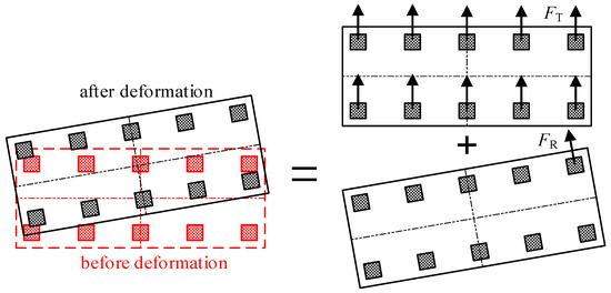
Figure 1.
Additional shear force of lateral force resistant members due to torsion.
Members located further from the rigid center with less stiffness will undergo greater lateral displacement, resulting in a substantial increase in the shared horizontal seismic shear force. This increase can cause the members to exceed their allowable resistance and deformation limits, leading to severe local damage, the failure of individual members, and potentially the collapse of the entire structure.
Reference [30] proposed an index to characterize the match between the shear force and lateral stiffness of lateral force-resisting components in non-rigid plate bent frame structures, known as the shear force lateral stiffness matching index β. This index is derived from the results of bidirectional seismic response spectrum enveloping. The shear force lateral stiffness matching index is defined as:
where Fi and Ki represent the shear force and lateral stiffness of the i-th lateral force-resisting column in a main direction under seismic loading, respectively. F0 and K0 represent the total shear force under seismic loading and total lateral stiffness of the structure in the same direction, respectively.
Under seismic loading, if the structure experiences only translational motion, the deformations of all lateral force-resisting components are consistent, and β = 1; if torsion is involved, β > 1. Therefore, β essentially represents the inconsistency in the deformation of lateral force-resisting components under seismic loading. A larger β indicates that the structure exhibits less translational motion. Factors influencing β include not only the torsional response of the structure but also the in-plane non-uniform deformation of the roof slab. Utilizing this index to represent the regularity of lateral force-resisting component configuration in non-rigid plate bent frame structures is considered reasonable [30].
2.2. Roof Slab Deformation Indices
As part of the horizontal load-bearing system in non-rigid plate bent frame structures, the roof slab significantly influences the cooperative behavior of vertical lateral force-resisting components. When the roof slab is non-rigid, the in-plane deformation of the roof slab cannot be neglected when considering the horizontal force distribution among lateral force-resisting components in non-rigid plate bent frame structures.
The deformation of a spatial element is generally a combination of rigid body translation, in-plane rigid body rotation, and in-plane bending deformation [31,32,33]. To further analyze the impact of these deformations (Figure 2) on β, we propose the following indices to characterize structural deformation: the point of maximum displacement lies between the displacements at both ends, with the corresponding interpolation representing the torsional deformation . The difference between the maximum displacement and the torsional deformation is the bending deformation . The ratio of the bending deformation to the maximum displacement is referred to as the bending deformation ratio Pb.
where umax represents the maximum displacement at the top of the column under unidirectional seismic loading. uB,1 represents the displacement at the left end post, and uB,n represents the displacement at the right end post, with the subscript n indicating the number of longitudinal spans. L is the dimension of the structure in the main direction, and x is the distance from the column with the maximum displacement to the leftmost column line.
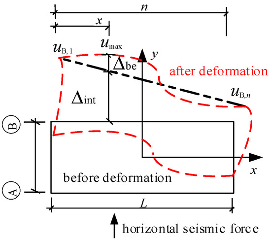
Figure 2.
Structural torsion under horizontal seismic loading.
Equation (2) represents the rigid body linear displacement and rigid body rotational displacement of the structure, namely, torsional deformation and translational displacement. However, the translational displacement of the structure generally does not change with the eccentricity. Therefore, Equation (2) can be considered a measure of the torsional deformation of the structure. Equation (3) corresponds to the residual deformation after removing the torsional deformation at the point of maximum displacement. This residual deformation quantifies the extent of the planar bending deformation of the roof panel, thus reflecting the bending deformation of the roof panel.
3. Properties and Influencing Factors of β
3.1. Example Design
Taking the airport concourse and the exhibition hall of the convention center as reference objects, their main feature is the extensive use of single-story frame structures [3], with rectangular or quasi-rectangular roof slabs. Based on the “Code for Anti-seismic design of Buildings” [10] and the “Standard for Design of Steel Structures” [23], a rectangular single-story frame structure example was designed as shown in Figure 3.
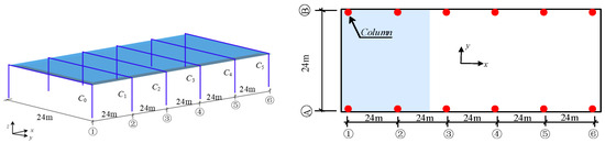
Figure 3.
Schematic of example model.
The structure uses Q355B with a transverse column spacing of 24 m and one span and a longitudinal column spacing of 24 m and five spans. The height of the roof-supporting columns is 5 m. The roof load is simplified to a permanent load of 1.5 kN/m2 and a live load of 0.5 kN/m2. The seismic precautionary intensity is 8 degrees (0.20 g), the site category is type III, the design seismic grouping is Group I, the seismic influence coefficient is 0.16, and the site period is 0.45 s.
To investigate the impact of eccentricity on β, eccentric loads were applied, as shown in Figure 4. By applying an additional Z-direction concentrated load at the top of the lateral force-resisting components along axes ① to axis ③, the centroid of the structure deviates from the geometric center while the position of the rigid center remains unchanged. The magnitude of the additional concentrated load is a multiple of the structural mass m0.
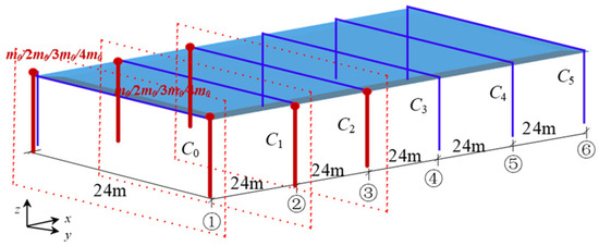
Figure 4.
Schematic of eccentric load application.
The model’s support columns have cross-sectional specifications of 290 × 14, arranged uniformly to support the roof slab. To investigate the impact of torsional stiffness on β, the cross-sectional size of the corner columns is increased. Specifically, the cross-sectional size of the corner columns on axes ① and axes ⑥ is increased to 450 × 22, while the other support columns remain at 290 × 14.
Additionally, it is assumed that the 120 mm thick concrete slab has infinite in-plane stiffness, with its in-plane compressive stiffness set to 1.00EA. Other conditions are based on a 120 mm thick concrete slab, with adjustments made by varying the panel thickness to explore the impact of roof stiffness. The varying calculation parameters are shown in Table 1.

Table 1.
Parameters of the calculation model.
3.2. Properties of β
To analyze the impact of lateral force-resisting component configuration on β, a panel stiffness of 0.01EA is used as an example. As shown in Figure 5, when the section size of corner columns increases from 290 × 14 to 450 × 22, β significantly increases.
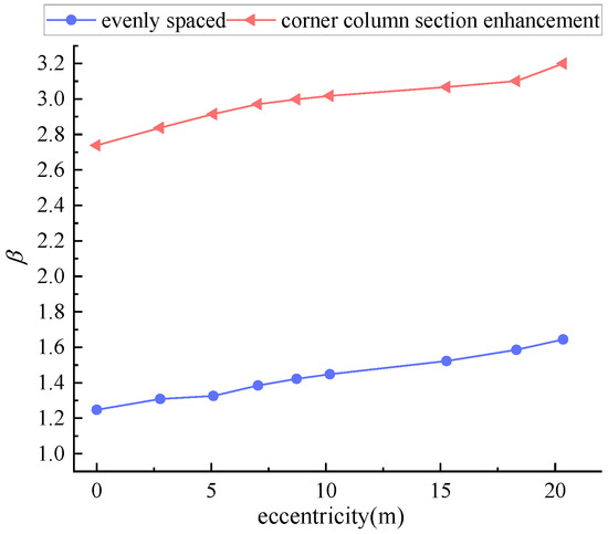
Figure 5.
Comparison of β for non-rigid plate bent frame structures (0.01EA) with different lateral force-resisting component configurations.
Taking support columns with a section size of 290 × 14 as an example, the influence of panel stiffness and eccentricity on β is investigated. Figure 6 demonstrates that, irrespective of the roof panel’s rigidity or elasticity, β increases with increasing eccentricity. For small eccentricities, β is negatively correlated with panel stiffness; at the same eccentricity, increased panel stiffness results in a smaller β. However, as eccentricity continues to increase, this trend reverses, and β begins to increase with panel stiffness at large eccentricities.
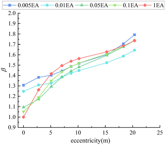
Figure 6.
β for different panel stiffness with uniformly arranged lateral force-resisting components.
These results indicate that β can simultaneously account for the influence of lateral force-resisting component configuration and panel stiffness on structural regularity.
Figure 5 and Figure 6 raise two issues that need to be discussed: (1) As seen in Figure 5, when the roof panel is non-rigid, β increases when the section size of the corner columns is enhanced, indicating an increase in the overall torsional stiffness of the structure; (2) In Figure 6, it is observed that with increasing eccentricity, the relationship between β and panel stiffness undergoes a shift. Initially, β decreases with increasing panel stiffness, but as eccentricity grows larger, this trend reverses and β begins to increase with panel stiffness, showing no consistent negative correlation.
This indicates that the changes in β involve the complex interplay of factors such as eccentricity, torsional stiffness, and roof panel deformation. The following parts will explore the impact of different factors on β.
3.3. Influence of Torsional Stiffness
When torsional effects are present, the contribution of vertical lateral force-resisting components to maintaining the overall stability of the building cannot be ignored [34]. With the structural panel stiffness set at 0.01EA, the impact of different torsional stiffness on various deformations of the roof panel is explored using two configurations: one with a uniform arrangement where all column sections are identical, and the other with enhanced section sizes at the corner columns.
As shown in Figure 7 and Figure 8, with increasing eccentricity, both torsional deformation and bending deformation increase for structures with uniformly arranged lateral force-resisting components and with corner columns having enhanced section sizes. This indicates that when the roof panel is a non-rigid plate, the roof panel of structures with uniformly arranged lateral force-resisting components and strengthened corner columns will experience significant bending deformation in addition to torsional deformation.
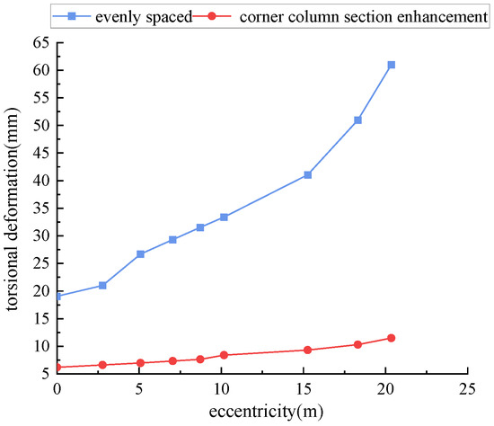
Figure 7.
Torsional deformation Δint of structures with uniform distribution and strengthened corner columns (0.01EA).
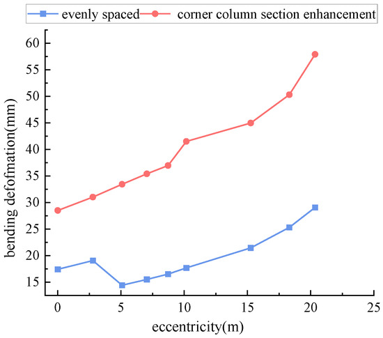
Figure 8.
Bending deformation Δbe of structures with uniform distribution and strengthened corner columns (0.01EA).
The result in Figure 9 shows that the primary deformation mode of the roof panel is bending deformation when corner columns are strengthened; however, it is torsional deformation when lateral force-resisting components are uniformly arranged. Strengthening the corner columns significantly increases the proportion of bending deformation Pb in the total deformation of the roof panel, indicating that additional non-uniform deformation arises due to the strengthening of the corner columns.
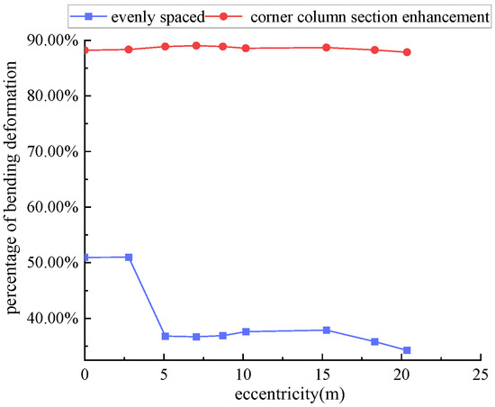
Figure 9.
Proportion of bending deformation Pb in structures with uniform distribution and strengthened corner columns (0.01EA).
It is evident that the configuration of lateral force-resisting components significantly affects the deformation of the structure under seismic loading, thereby impacting β. For structures with strengthened corner columns, although the torsional stiffness of the structure increases, the distribution of lateral stiffness becomes more uneven, leading to greater bending deformation of the roof panel and a consequent significant increase in β.
3.4. Influence of Eccentricity
The eccentricity ratio affects the vibration characteristics of building structures, increasing the torsional effects [35]. Taking the configuration of uniformly arranged lateral force-resisting components as an example, Figure 10 and Figure 11 illustrate the effects of different panel stiffness and eccentricities on the bending deformation of the structure and the proportion of bending deformation Pb. Table 2 shows the bending deformation of different axial columns for a structure with a roof slab stiffness of 0.01EA panel stiffness. From Figure 10 to Figure 11, it can be observed that the bending deformation of the structure under different roof panel stiffness and eccentricities exhibits a non-monotonic trend. This is related to the shift in the maximum displacement measurement point: as eccentricity increases, the maximum displacement point moves from the center of the roof panel toward the end column, i.e., from the point of concentrated uneven deformation toward the direction of eccentricity, as shown in Figure 12. Table 2 indicates that the bending deformation of a non-rigid plate bent frame structure’s roof panel decreases from the center toward the ends. Therefore, as the maximum displacement point moves towards the post ends with increasing eccentricity, the bending deformation of the structure and the proportion of bending deformation Pb exhibit a non-monotonic trend.
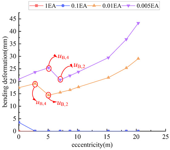
Figure 10.
Bending deformation Δbe of structures with different panel stiffness under uniform distribution of lateral force-resisting components.
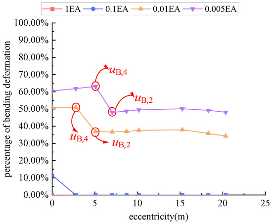
Figure 11.
Proportion of bending deformation Pb in structures with uniform distribution of lateral force-resisting components.
Table 2.
Bending deformation Δbe for 290 − 0.01EA (mm).
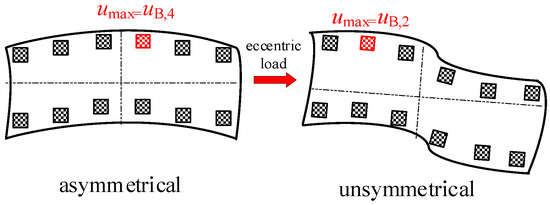
Figure 12.
Shift in maximum displacement column measurement point with increasing eccentricity.
Figure 13 shows the effects of different panel stiffnesses and eccentricities on the torsional deformation of the structure. As seen in Figure 13, the torsional deformation of structures with different panel stiffness monotonically increases with increasing eccentricity.
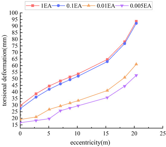
Figure 13.
Torsional deformation Δint of structures with different panel stiffness under uniform distribution of lateral force-resisting components.
3.5. Influence of Panel Stiffness
The roof slab primarily bears the vertical loads while determining the distribution of horizontal loads among the vertical lateral force-resisting components [36]. Taking the configuration of uniformly arranged lateral force-resisting components and an eccentricity upper limit of 8.720 m (eccentricity ratio of 7.3%) as examples, Figure 14, Figure 15, Figure 16 and Figure 17 illustrate the effects of different panel stiffness and eccentricities on the torsional deformation , base shear force, bending deformation , and the proportion of bending deformation Pb of the structure, respectively.
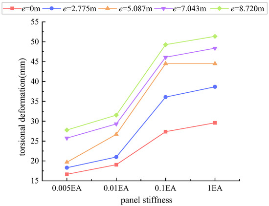
Figure 14.
Influence of different panel stiffness on torsional deformation Δint.
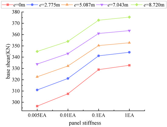
Figure 15.
Influence of different panel stiffness on base shear.
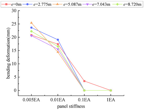
Figure 16.
Influence of different panel stiffness on bending deformation Δbe.
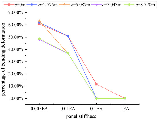
Figure 17.
Influence of different panel stiffness on the proportion of bending deformation Pb.
As shown in Figure 17, with increasing eccentricity, the deformation at the maximum displacement point of a non-rigid plate gradually transitions from bending to torsional deformation. Figure 14, Figure 15 and Figure 16 demonstrate that at a constant eccentricity, increasing panel stiffness leads to higher base shear forces, greater torsional deformation, and reduced bending deformation. This indicates that the trends of torsional and bending deformations are inversely related to panel stiffness.
Combining Section 3.3 and Section 3.4, the trend of β exhibiting a shift in behavior with increasing eccentricity can be elucidated as follows: Both overall structural torsion and roof bending deformation induce a discrepancy between the shear force sustained by lateral force-resisting components and their lateral stiffness. At a constant eccentricity, with increasing panel stiffness, structural torsional deformation increases while bending deformation decreases. Compared to rigid plate bent frame structures, non-rigid plate bent frame structures exhibit additional bending deformation at small eccentricities, resulting in consistently higher β values for non-rigid plate bent frame structures than for rigid plate bent frame structures. Hence, at small eccentricities, β is negatively correlated with panel stiffness. However, as eccentricity increases, the proportion of structural torsional deformation rises while the proportion of bending deformation declines. When the primary deformation mode of the roof panel transitions to torsional deformation, the β for rigid plate bent frame structures exceeds that for non-rigid plate bent frame structures. Therefore, at large eccentricities, panel stiffness and β are not necessarily negatively correlated.
4. Conclusions
This study evaluated the applicability of the shear force lateral stiffness matching index in non-rigid frame structures and analyzed its variation patterns under different parameter conditions. Through numerical simulation, the deformation indices of the roof slab in frame structures were obtained under various parameters, revealing the influence mechanisms of factors such as structural eccentricity, torsional stiffness, and roof slab stiffness on the shear force lateral stiffness matching index.
- (1)
- The deformation response of the roof slab under seismic loading can be divided into torsional deformation Δint and bending deformation Δbe. The proposed torsional and bending deformation indices can accurately quantify these two deformation responses, describing the horizontal deformation characteristics of lateral force-resisting components in non-rigid plate bent frame structures.
- (2)
- Although strengthening the corner column sections can increase the structural torsional stiffness, it also increases the in-plane bending deformation. Strengthening the corner column sections increases the unevenness of the lateral stiffness distribution, resulting in a significant increase in the shear force lateral stiffness matching index.
- (3)
- For non-rigid plate bent frame structures, when the eccentricity is small, the maximum displacement under seismic loading is primarily controlled by bending deformation. As eccentricity increases, the main component of maximum displacement gradually transitions from bending deformation to torsional deformation.
- (4)
- The shear force lateral stiffness matching index considers the inconsistency in the horizontal displacement response of lateral force-resisting components caused by various deformations of the roof panel. At a constant eccentricity, with increasing panel stiffness, torsional deformation increases while bending deformation decreases. The combined effect results in panel stiffness not necessarily being negatively correlated with β.
- (5)
- When eccentricity is present in the structure, selecting an appropriate panel stiffness is essential to ensuring the consistency of lateral force-resisting component deformation. A larger panel stiffness does not necessarily result in a larger translational component of the structural seismic response.
- (6)
- This study explored the influence mechanisms of various parameters on the shear force lateral stiffness matching index. The analysis was limited to single-span, single-story frames, and future research could extend to more complex cases, particularly those involving complex plans and multi-span structures. Additionally, the current study mainly focused on elastic seismic responses; future research could explore the nonlinear behavior of the shear force lateral stiffness matching index under elastoplastic seismic conditions to optimize seismic design further.
Author Contributions
Conceptualization, P.Z.; methodology, P.Z.; formal analysis, Y.L.; investigation, Y.L.; writing—original draft, Y.L.; writing—review and editing, Y.L., W.X., Q.Z., M.M. and C.Y.; project administration, Y.L.; funding acquisition, P.Z. All authors have read and agreed to the published version of the manuscript.
Funding
The authors express their sincere gratitude for the financial support provided by the National Key Research and Development Program of China [Grant No. 2022YFC3002300].
Data Availability Statement
Data are contained within the article.
Conflicts of Interest
Authors Yulong Li, Pengfei Zhao, Wen Xue, Qiang Zhang, Ming Ma and Changjie Ye were employed by the company China Building Technique. The remaining authors declare that the research was conducted in the absence of any commercial or financial relationships that could be construed as a potential conflict of interest.
References
- Krishna, P. A Review of Developments in Steel: Implications for Long-Span Structures. Trans. Indian Inst. Met. 2021, 74, 1055–1064. [Google Scholar] [CrossRef]
- Dong, S.; Xing, D.; Zhao, Y. Application and Development of Modern long-span Spatial Structures in China. Front. Struct. Civ. Eng. 2012, 6, 224–239. [Google Scholar] [CrossRef]
- Cheng, H. Modern Light Steel Structure Buildings and Their Application in China. China Build. Met. Struct. 2022, 7, 39–41. [Google Scholar]
- Zhao, P. Design of Special-Shaped Components in long-span Structures. Build. Struct. 2013, 43, 36–40. [Google Scholar]
- International Code Council. 1997 Uniform Building Code, Vol. 2: Structural Engineering Design Provisions; International Conference of Building Officials: Whittier, CA, USA, 1997. [Google Scholar]
- FEMA. NEHRP Recommended Provisions for Seismic Regulations for New Buildings and Other Structures (FEMA 450); Building Seismic Safety Council (BSSC): New York, NY, USA, 2003. [Google Scholar]
- International Code Council. International Building Code 2003; International Code Council: Washington, DC, USA, 2003. [Google Scholar]
- Cheng, S. Structural Eurocodes (EC8); Institute of Engineering Earthquake Research, China Academy of Building Research: Beijing, China, 1997. [Google Scholar]
- NZS4203: 1992; Code of Practice for General Structural Design and Design Loadings for Buildings. Standards Association of New Zealand: Wellington, New Zealand, 1992.
- GB 50011-2010; Code for Anti-Seismic Design of Buildings. China Architecture & Building Press: Beijing, China, 2016.
- JGJ3-2010; Technical Specification for Concrete Structures of Tall Buildings. China Architecture & Building Press: Beijing, China, 2010.
- Xu, P.; Huang, J.; Wei, C. Torsional vibration effects of high-rise building structures under earthquake action. Build. Sci. 2000, 1, 4–9. [Google Scholar]
- Cai, J.; Pan, D.; Huang, Y. Study on the control of torsional vibration effects in high-rise building structures. Eng. Mech. 2007, 7, 116–121. [Google Scholar]
- Liu, J.; Li, Y. Influence of Eccentricity Variation on Period Ratio of High-Rise Building Structures. Wuhan Univ. Technol. J. 2010, 32, 55–60. [Google Scholar]
- Wei, L.; Wang, S.; Wei, C. Control issues of translational period and torsional period ratio in high-rise buildings. Build. Struct. 2014, 1–3+13, 44. [Google Scholar]
- Liu, L.P.; Li, A.L.; Li, Y.M.; Fan, S.; Han, J. Applicability Analysis of Torsional Control Indicators in Uneven-Height Grounded Frame Structures. Earthq. Eng. Eng. Vib. 2014, 34, 680–685. [Google Scholar]
- Wang, J.; Zhao, D.; Wang, D.; Liu, G. Study of Torsional Response Control Index of the Spreading Layer upon Layer. Build. Sci. 2016, 32, 25–29. [Google Scholar]
- Han, Y. Study on Seismic Torsional Effects of Complex Eccentric Structures. Master’s Thesis, Tianjin University, Tianjin, China, 2017. [Google Scholar]
- Jahami, A.; Temsah, Y.; Khatib, J.; Baalbaki, O.; Darwiche, M.; Chaaban, S. Impact behavior of rehabilitated post-tensioned slabs previously damaged by impact loading. Mag. Civ. Eng. 2020, 93, 134–146. [Google Scholar]
- Paul, B.; Roy, K.; Ghosh, K.; Fang, Z.; Maity, S.; Lim, J.B.P. Numerical Modelling of Side-Plate Connection for Cold-Formed Steel Nested Tapered Box Beam Portal Frame. In Recent Developments in Structural Engineering; Goel, M.D., Kumar, R., Gadve, S.S., Eds.; Volume 1 SEC 2023 Lecture Notes in Civil Engineering; Springer: Singapore, 2024; Volume 52. [Google Scholar]
- Sánchez-Olivares, G.; Espín, A.T. Design of planar semi-rigid steel frames using genetic algorithms and Component Method. J. Constr. Steel Res. 2013, 88, 267–278. [Google Scholar] [CrossRef]
- He, M.; Ma, Z.; Ma, R.; Li, Z. Light Wood-steel Hybrid Performance on Transferring Horizontal Loads. Tongji Univ. Nat. Sci. Ed. 2014, 42, 1038–1043. [Google Scholar]
- GB 50017-2017; Standard for Design of Steel Structures. China Architecture & Building Press: Beijing, China, 2018.
- JGJ 257-2012; Technical Specification for Cable Structures. China Architecture & Building Press: Beijing, China, 2012.
- Shao, F.; Chen, Z.; Ge, H. Parametric analysis of the dynamic characteristics of a long-span three-tower self-anchored suspension bridge with a composite girder. ABEN J. 2020, 1, 10. [Google Scholar] [CrossRef]
- Zhao, P.; Chen, X.; Liu, X. Preliminary Study on Calculation Method and Influence of Regularity indices for long-span Structures. Archit. Sci. 2022, 38, 17–26. [Google Scholar]
- Liu, Y.; Xiong, J.; Mo, L. Structural Design of a Commercial Complex in Changsha. Build. Struct. 2021, 51, 36–41+6. [Google Scholar]
- Yu, Z. Design and Analysis of the Main Structure of the Expo Cultural Center. J. Build. Struct. 2010, 31, 95–102. [Google Scholar]
- Liang, Q.; Wu, J.; Lu, G.; Hu, J. Structural Design and Analysis of a Super-High Building in Nanjing, China. Sustainability 2023, 15, 6521. [Google Scholar] [CrossRef]
- Zhao, P.; Xue, W.; Li, Z. Study on the Regularity Indicator for Single-Span Frame Structures Considering Planar Bending Deformation. J. Build. Struct. 2024, 45, 50–61. [Google Scholar]
- Sun, P. Deformation Decomposition and Basic Application of Elastic Structures. Master’s Thesis, Zhengzhou University, Zhengzhou, China, 2016. [Google Scholar]
- Tseng, W.; Tarn, J. Exact Elasticity Solution for Axisymmetric Deformation of Circular Plates. J. Mech. 2015, 31, 617–629. [Google Scholar] [CrossRef]
- Ye, T.; Jin, G.; Liu, Z. Analysis of the Influence of Transverse Shear and Stretching Deformation on the Vibration Characteristics of Laminated Plates. J. Vib. Shock 2019, 38, 118–125. [Google Scholar]
- De-La-Colina, J.; Valdés-González, J.; González-Pérez, C.A. Dependency of the Accidental Torsion Building Response on Both Live-to-Dead Load Ratio and Material Stiffness Variation. J. Civil Eng. 2024. [Google Scholar] [CrossRef]
- Tabatabaei, R. Torsional Vibration of Eccentric Building Systems. In Recent Advances in Vibrations Analysis; InTech: London, UK, 2011. [Google Scholar]
- Sucuoğlu, H.; Akkar, S. Analysis Procedures and Seismic Design Principles for Building Structures. In Basic Earthquake Engineering; Springer: Cham, Switzerland, 2014. [Google Scholar]
Disclaimer/Publisher’s Note: The statements, opinions and data contained in all publications are solely those of the individual author(s) and contributor(s) and not of MDPI and/or the editor(s). MDPI and/or the editor(s) disclaim responsibility for any injury to people or property resulting from any ideas, methods, instructions or products referred to in the content. |
© 2024 by the authors. Licensee MDPI, Basel, Switzerland. This article is an open access article distributed under the terms and conditions of the Creative Commons Attribution (CC BY) license (https://creativecommons.org/licenses/by/4.0/).