Article

Research on Temperature Control of Mass Concrete for Multi-Tower Cable-Stayed Bridge Cap during Construction

1
School of Civil Engineering and Communication, North China University of Water Conservancy and Hydroelectric Power, NO. 36 Beihuan Rd., Jingshui District, Zhengzhou 450011, China
2
China Railway No.3 Engineering Group Co., Ltd., Beijing 030024, China
*
Author to whom correspondence should be addressed.
Buildings 2024, 14(10), 3112; https://doi.org/10.3390/buildings14103112 (registering DOI)
Submission received: 1 July 2024 / Revised: 30 July 2024 / Accepted: 2 August 2024 / Published: 28 September 2024
(This article belongs to the Section Construction Management, and Computers & Digitization)

Abstract

:
In the construction process of mass concrete structures, the large temperature gradient due to exothermic hydration makes the mass concrete highly susceptible to cracking. This paper carried out research on temperature control methods of mass concrete for the purpose of ensuring construction quality based on the construction of Fengyi cable-stayed bridge caps. Firstly, the temperature and stress change rule in the concrete pouring process of the caps was analyzed though the finite element method (FEM). Then, targeted-oriented comprehensive temperature control schemes were formulated according to the structural characteristics and construction environment of the cap, including the optimization of the material ratio, the arrangement of crack-resistant reinforcing steel, the design of a water pipe cooling scheme and reasonable maintenance. Finally, the whole bridge cap construction process using the optimized water pipe cooling solution was monitored, and the temperature gap between inside and outside the concrete satisfied the specification requirements rigorously. In the concrete demolding session, the concrete surface was smooth and no cracks were found, which indicates the temperature control scheme is reasonable and effective. The research results have reference significance for the pouring and temperature control of mass concrete for bridge caps.

1. Introduction

With the rapid development of construction technology and design theory, the scale of building structures and the span of bridge structures are becoming larger and larger, resulting in the appearance of more and more mass concrete structures. When the minimum size of the concrete structure is over 1 m, or when harmful cracks are expected to result from temperature changes and shrinkage caused by hydration of the cementified material in the concrete, the concrete can be regarded as mass concrete [1]. Mass concrete has the characteristics of a thick structure, large volume and complex construction. In addition to ensuring the requirements of strength and stiffness, cracks must be controlled for mass concrete. Concrete is a kind of bad thermal conductivity material. The temperature difference between the inside and outside of the concrete during pouring is too large due to the large amount of heat generated by the hydration of the cement. Under the action of internal and external constraints, temperature stress will be generated in the concrete. When the stress exceeds the tensile strength of the material, it can easily cause cracking of the concrete and reduce the bearing capacity of the structure; then, it would seriously affect the safety and durability of the concrete structure [2]. Therefore, how to effectively prevent concrete cracking caused by temperature stress in mass concrete construction is a long-term concern and research issue for engineers and technicians [3].
Domestic and foreign scholars and engineers have carried out a lot of research work on temperature control during the construction of mass concrete and obtained a lot of research results. This is mainly manifested in materials, theoretical methods, and temperature control measures for cracking prevention. For example, the physical and chemical processes of cement hydration, the adiabatic temperature rise mode, concrete mixing ratio and mechanical properties, etc., have guiding significance for theoretical research and engineering practice. Numerical analysis based on the finite element method is an important means to study the internal temperature and stress distribution of mass concrete. The numerical analysis method can more intuitively reveal the distribution and evolution of temperature and stress inside the mass concrete construction process, and provide guidance for the development of reasonable temperature control measures. Truman et al. [1] and Tajima et al. [4] deduced the calculation formula of the hydration heat of mass concrete, which provides a theoretical basis for the calculation of mass concrete temperature. Wilson et al. [5] studied the temperature field of mass concrete by the finite element analysis method, and applied it to practical engineering, successfully. Wang Jianqun et al. [6] take a cross-sea cable-stayed bridge as the research object, and use MIDAS/FEA to establish a finite element model for the analysis of the hydration heat temperature field of the bridge cap. Through this model, they studied the influence of the concrete mixing ratio, molding temperature, ambient temperature, cooling water flow and water temperature and stripping time on temperature stress. Wen Dean et al. [7] also used MIDAS/FEA to simulate the hydration heat temperature field of a pier cap, and compared the calculation results with field measured values to verify the validity of the finite element model. In order to reveal the internal temperature field characteristics of varying structures, scholars have carried out a series of simulation studies on the heat of hydration of mass concrete based on Ansys 12.0 and Abaqus 6.14 software [8,9,10,11,12]. He Yun et al. [13] studied the influence of pouring layer thickness, cooling water flow rate and cooling water temperature on concrete temperature and stress by numerical simulation of different pouring schemes of bridge tower cap concrete by using a line element decoupling algorithm. Wang Qiong et al. [14] used the CFD method to simulate the temperature field of mass concrete of a beam cap after pouring. The calculation results show that a cooling water pipe scheme is effective in controlling the maximum internal temperature, mitigating the temperature difference and reducing the cooling rate, which were in good agreement with the engineering measurement. In addition, Liu et al. [15] used the thermal flow coupling model to study the temperature and stress variation of dam mass concrete.
In order to reduce the internal temperature of mass concrete, embedded cooling water pipes are usually used in construction. Zhu Bofang [16] deduced the theoretical solution of the internal temperature field of mass concrete under the combined action of a cooling water pipe and surface heat dissipation and established an equivalent heat conduction equation. Based on this equivalent heat conduction equation, Yang et al. [17] compiled a finite element analysis program and compared the calculation results with the measured data of an arch dam to verify the validity of the theoretical model. Lu et al. and Si et al. [18,19] used the thermal flow coupling model, which can consider the heat convection exchange between the cooling water pipe and the concrete to study the temperature field of a pier cap, and discussed the influence of the parameters such as the water temperature, flow rate and water pipe spacing of the cooling water on the temperature distribution in the concrete. Geng et al. and Gu et al. [20,21] used MIDAS/FEA to analyze the influence of the number of cooling water pipes and the spatial layout on the internal temperature and stress field of mass concrete. The study found that the reasonable layout of the cooling water pipes can reduce the tensile stress of the concrete surface and, compared with the traditional rectangular and plum-shaped layout, a well-shaped cooling water pipe can significantly improve the temperature and stress distribution inside the concrete. Zhang et al. [22] used MIDAS/FEA to analyze the control effect of a spatial three-dimensional cooling pipe network on the internal temperature stress of mass concrete. It is found that the spatial cooling network can reduce the high temperature area inside the concrete and effectively control the temperature stress within the allowable range. Based on the method of numerical simulation and field measurement, Li et al. [23] studied the variation law of temperature and stress field inside a pier cap and put forward the idea that the flow direction of cooling water should be changed regularly in the process of temperature control.
In addition to the use of cooling water pipes, measures such as optimizing concrete raw materials and mixing ratio, controlling the molding temperature and surface curing can also effectively prevent temperature cracks in mass concrete structures. Sun et al. and Miao et al. [24,25] studied the influence of the change in concrete ratio on the temperature and stress inside mass concrete by numerical analysis. Yuan et al. and Yan et al. [26,27] studied the influence of cement type and strength grade on the temperature stress of concrete. The results show that the use of low-hydration-heat composite cement or high-grade ordinary Portland cement is beneficial to the control of temperature cracks. Wan et al. [28] used the numerical method to analyze the temperature field of the mass concrete of a bridge cap. The research shows that a series of measures such as optimizing the mixing ratio design, thinning the layered casting thickness, strengthening the heat dissipation efficiency, reducing the temperature of concrete casting into the mold and the thermal insulation maintenance of the full water storage can effectively eliminate the temperature cracks generated during the construction of the mass concrete. Xu et al. [29] studied the effects of cement hydration control materials and composite expansion agents on the crack resistance of high-strength concrete through scale model tests. The results show that the addition of these admixtures can significantly reduce the tensile stress caused by concrete shrinkage and reduce the risk of structural cracking.
Based on numerical analysis and engineering practice, Li et al. [30] proposed the dynamic design curing method for the mass concrete of a pier cap during construction. Through the design of the optimal curing curve of concrete and timely dynamic adjustment of maintenance measures, the formation of temperature cracks in the mass concrete of a pier cap can be effectively controlled. In order to cope with the unfavorable factors during the construction of pier caps in winter, Qin et al. [31] took a series of measures to avoid harmful cracks.
Although a lot of research has been carried out on the temperature control and anti-crack technology of mass concrete [32,33,34,35], due to the large differences in the construction environment, structural form and local engineering material performance of specific engineering projects, the existing engineering experience cannot be completely copied, and it is necessary to formulate specific temperature control measures based on the characteristics of engineering projects [36,37,38,39,40]. Taking Fengyi Bridge as the engineering background, this paper establishes a finite element model for the hydration heat analysis of the main tower cap in the high-temperature environment and obtains the temperature and stress distribution of the concrete inside the cap during the construction period. This paper proposes the optimization method for the concrete mixing ratio and cooling water pipeline layout to solve the problem that the cable-stayed bridge cap is prone to cracking. Moreover, this paper puts forward a dynamic adjustment method for temperature control in the whole process of bridge cap construction based on the external and internal temperature of mass concrete. The smooth surface of the concrete after demolding verifies the effectiveness of the temperature control method for mass concrete proposed in this paper.

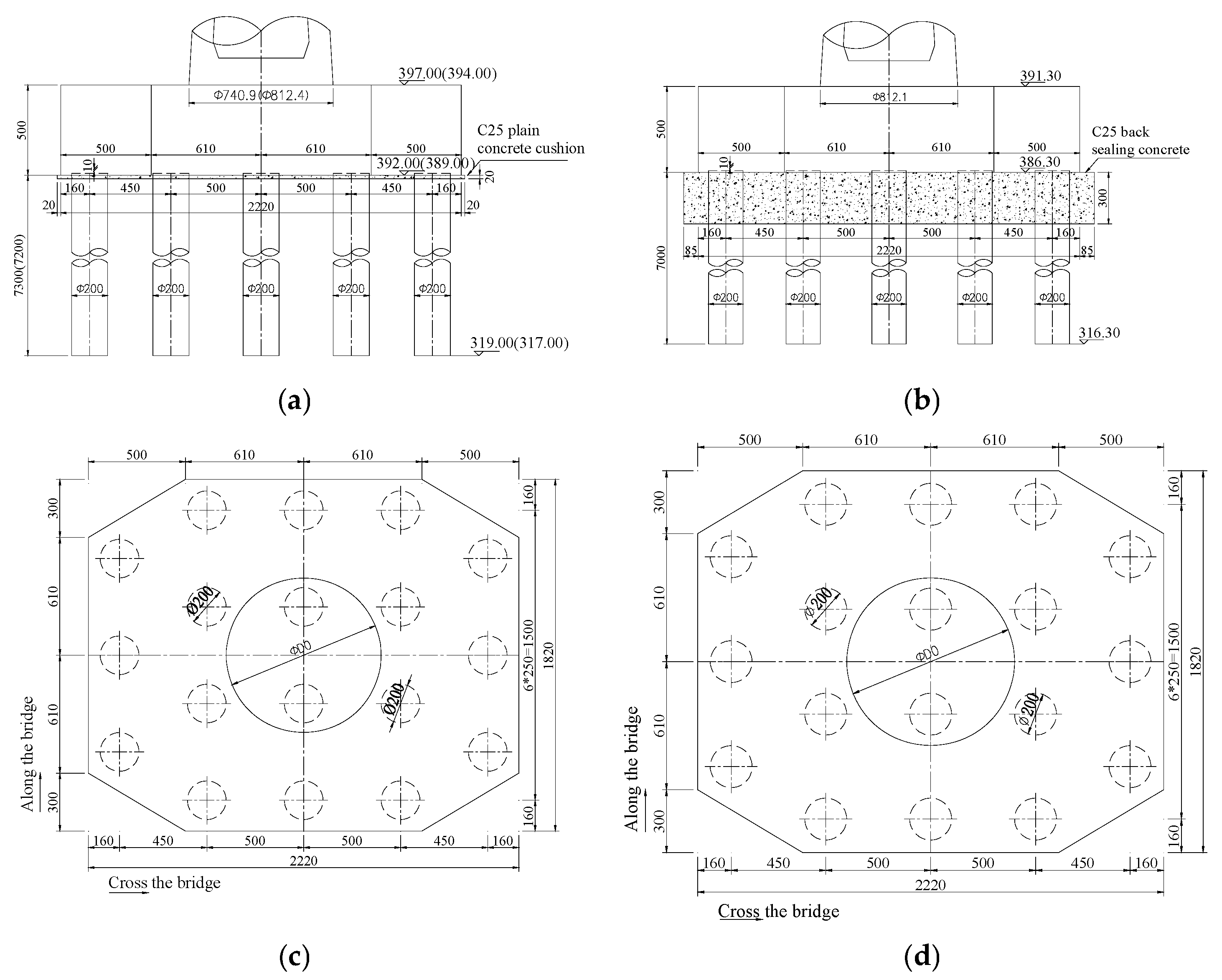
2. Engineering Overview

This paper carried out a series of studies based on Fengyi Bridge, including proposing the finite element analysis method to study the variation rule of temperature and stress inside the concrete during the mass concrete casting process at the cable-stayed bridge cap, and developed corresponding temperature control and anti-cracking schemes. Subsequently, the temperature monitoring was carried out during mass concrete casting and molding, and applied temperature control strategies that could be adjusted in real time to successfully avoiding cracking during the construction period of the mass concrete. Fengyi Bridge is a three-tower cable-stayed bridge with span of 526 m (87 m + 176 m + 176 m + 87 m). The width of the top and bottom of the main girder is 57 m and 43.9 m, respectively, and bilateral steel box girders are connected by a steel cross beam. The height of the main tower is 89.27~94.99 m, and the schematic diagram can be found in Figure 1. The dimension of the pile cap under the main tower is 18.2 m × 22.2 m × 5.0 m (longitudinal direction × transverse dimension × height). There are four chamfers (size of 0.5 m × 3 m) at the corners and 18 drilled grouting piles with a diameter of 2.0 m are arranged under the pile cap, as shown in Figure 2.

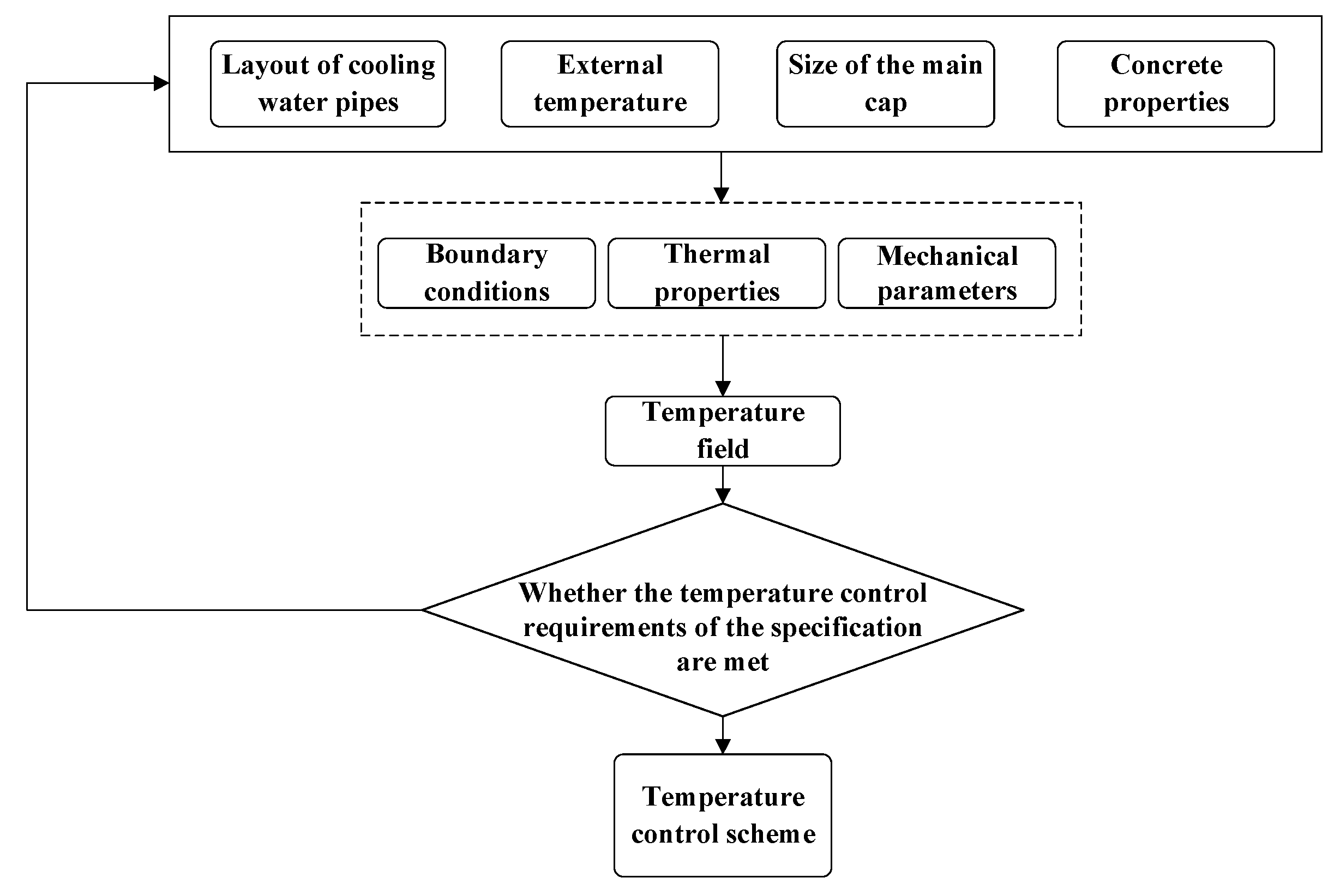
3. Design of Temperature Control Scheme for Mass Concrete Cap

To avoid harmful temperature cracks in the mass concrete of the pier cap during the construction period, it is essential to formulate a specific temperature control scheme based on the actual engineering structure and construction environment. The contents included the following aspects: (i) selection of raw materials and design of concrete mix ratio; (ii) layered pouring method of mass concrete; (iii) layout scheme of cooling water pipes; (iv) maintenance measures after concrete pouring; and (v) the internal temperature. The stress changes of mass concrete during pouring are calculated and analyzed by the numerical simulation method, and the temperature control measures are adjusted or improved according to the calculation results. The temperature control flowchart is shown in Figure 3.

3.1. Raw Materials and Concrete Mix Ratio

Reducing the heat of hydration is an effective method to reduce the temperature difference between the inside and outside of concrete, and the heat of hydration is mainly generated in the process of forming cementing materials through chemical reactions of cement with water. Therefore, the amount of cement can be reduced by adjusting the type of cement and adding a water-reducing agent and fly ash to reduce the heat of hydration under the premise of meeting the strength qualification [41,42,43], thus avoiding harmful cracks caused by the significant temperature difference between the inside and outside of the concrete.
The strength of the cap concrete in this project is C40. Combined with the construction environment of this project, the selected concrete raw materials are shown in Table 1. The P·O 42.5 low-alkali cement produced by Jidong Company, Tangshan, China, is chosen to effectively prevent an alkali–aggregate reaction and avoid cracking and collapse of the mass concrete. Moreover, a polycarboxylic acid superplasticizer is utilized to reduce the amount of cement per cubic meter of concrete and decrease the heat of hydration in the concrete pouring process, but the amount of water-reducing agent must be reasonably considered to ensure the time requirement of concrete pouring construction. Furthermore, first-class fly ash needs to be added to the complex to reduce the water consumption per unit volume of concrete to ensure the operational performance of the concrete. In addition, medium sand with a fineness modulus of 2.6–2.8 and a clay content of less than 3% is used as a fine aggregate; crushed stone with a continuous gradation of 5–25 mm and a clay content of less than 1% is used as a coarse aggregate. According to the selected raw materials, the mix ratio design of C40 concrete for the cap is shown in Table 1.

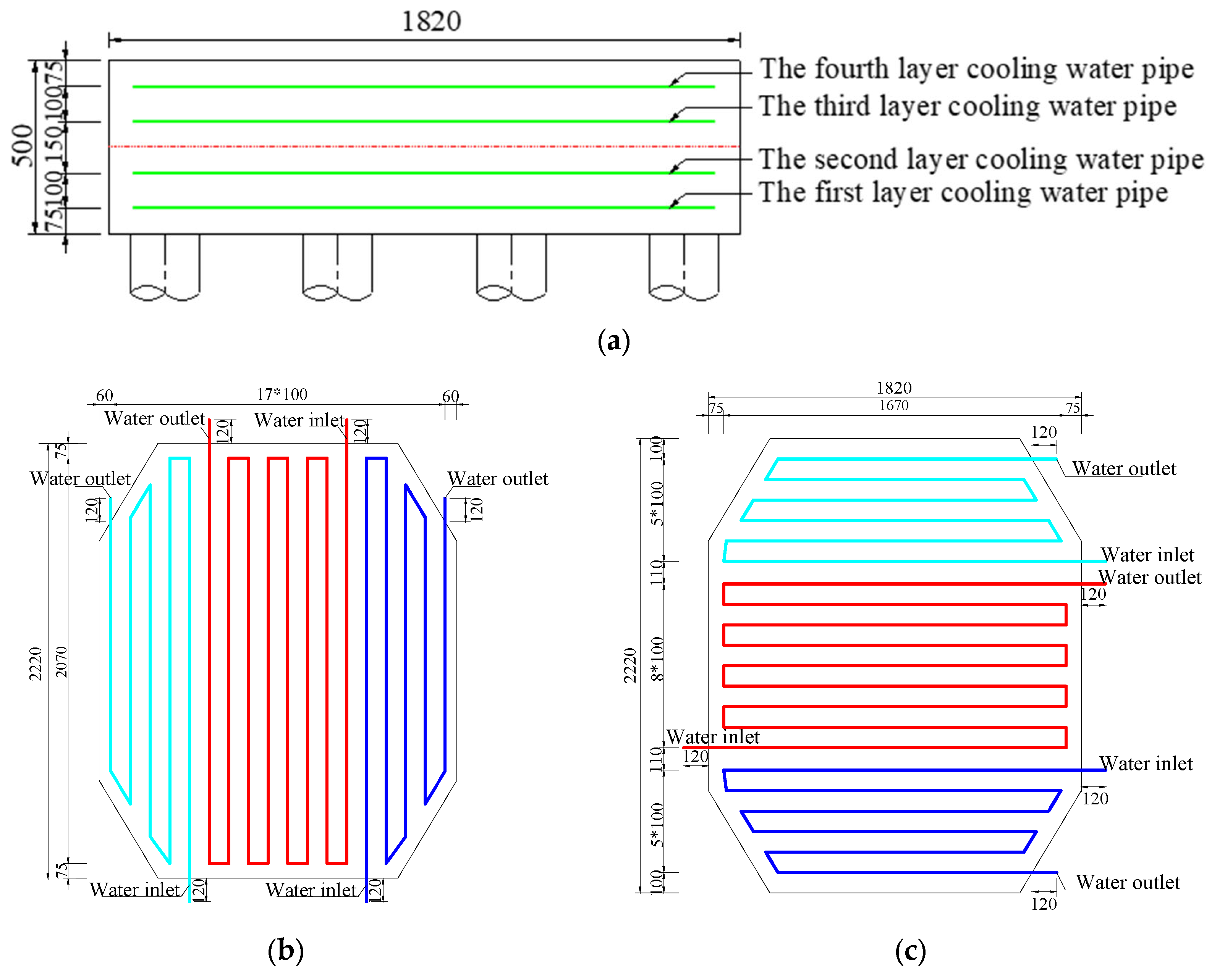
3.2. Layered Pouring Method and Cooling Water Pipe Arrangement

The thickness of different pouring blocks of mass concrete is proportional to the adiabatic temperature rise rate of concrete. The larger the thickness, the slower the heat dissipation and the faster the temperature rise. To slow down the maximum temperature rise of mass concrete, the construction of one bridge cap is poured into two layers. The thickness of each layer is 2.5 m, and the single pouring volume is 2338 m3.
In addition to reducing the heat of hydration by adjusting the concrete mix ratio, cooling pipes are laid inside the structure to take away the heat and reduce the temperature difference between the inside and outside of the concrete during the construction period. Moreover, the cooling water pipes of the cap have a wall thickness of 4 mm and an inner diameter of φ45 mm, and the cooling water pipe network is set up in layers according to the principle that the cooling water flows from the thermal center area (the middle part of the cap) to the edge area. In particular, the two layers of the cooling water pipe network are arranged vertically within the thickness range of 2.5 m with a vertical spacing of 1.0 m. Furthermore, each layer of the cooling water pipe network is divided into three areas along the horizontal direction, and each area is arranged with a set of cooling water pipe networks that can independently control the water inlet and outlet. In addition, the horizontal spacing between adjacent water pipes is 1.0 m, and the outermost water pipe is 0.75 m away from the nearest edge of the concrete. The exact location of the arrangement is shown in Figure 4 below.

3.3. Maintenance Measures

Reasonable insulation measures are used to effectively control the temperature difference between the inside and the surface of mass concrete and the temperature difference between the surface of the concrete and the environment to avoid harmful temperature cracks. In addition, as the early concrete is susceptible to shrinkage cracks, it is essential to take measures to keep the surface of the concrete wet to avoid the formation of shrinkage cracks. Considering the time interval in which cracks are prone to occur, temperature-controlled anti-cracking monitoring of concrete was continued up to 10 days after the removal of the formwork. Combined with the construction environment of the project, the maintenance measures included the following characteristics:
(1) Strengthening the concrete surface by insulation and water curing, reducing the concrete surface heat loss and the temperature difference between the concrete surface and the external environment. When the concrete is poured and the initial setting is completed, the thermal insulation measures are used for thermal insulation and moisturizing maintenance. In addition, the formwork is covered with insulation material around the cap for maintenance.
(2) Injecting circulating hot water into the pit around the cap for heat maintenance to reduce the temperature difference between the inner surface of the concrete and the surface and the environment, while water storage maintenance is adopted on the top surface of the cap.
(3) When the actual temperature difference approaches the preset maximum value, increasing the thickness of the cover and spray hot water curing.
(4) When the strength of concrete is greater than 10 MPa, and the temperature difference between inside and outside is less than 20 °C, the formwork can be removed. After removing the formwork, it is necessary to continue to implement insulation and moisturizing measures to control the temperature difference between the water temperature of the sprayed water and the concrete surface to within 20 °C.

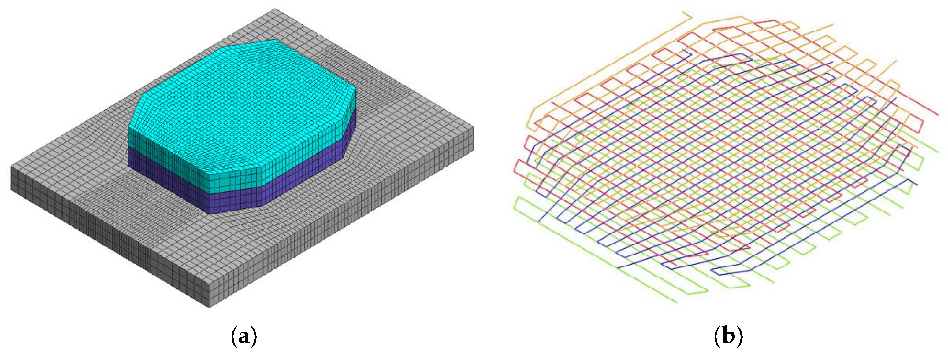
4. Numerical Simulation Analysis

4.1. Calculation Theory and Principle

The essence of calculating the internal temperature field of concrete is to obtain the solution of the heat conduction equation under specific boundary conditions and initial conditions. The heat conduction equation of a three-dimensional transient temperature field is as follows [44]:
T τ = a 2 T x 2 + 2 T y 2 + 2 T z 2 + θ τ
where a is thermal diffusivity a = λ c ρ , c is heating capacity, ρ is density, τ is time, θ is the adiabatic temperature rise of concrete and λ refers to the thermal conductivity of concrete.
In order to solve the above temperature field equation, the initial conditions and boundary conditions need to be determined as follows.
(1) Initial conditions of heat transfer
The known function of the temperature field coordinates x , y , z is T 0 x , y , z in the initial stage of heat transfer. This means when t = 0 the distribution of initial temperature can be considered as a constant and when t = 0   T x , y , z , 0 = T 0 .
(2) The boundary conditions of heat transfer can be defined as following four categories:
Boundary condition 1: Temperature is a function of time:
T t = f t
Boundary condition 2: The heat flux of the concrete surface is a function of time:
λ T n = f t
Boundary condition 3: When the concrete is in contact with the air, it is assumed that the heat through the concrete surface is proportional to the difference between the concrete surface temperature and the air temperature:
λ T n = β T T n
Boundary condition 4: For a solid with good contact, the temperature and heat flow on the contact surface are continuous:
T 1 = T 2 k 1 T 1 n = k 2 T 2 n
The top surface of the foundation slab, the bottom surface of the foundation and the side surface can usually adopt the first type of boundary condition. The second boundary condition can be used at the symmetry of the one quarter foundation slab model and the bottom of the foundation far from the concrete. The top surface of the foundation in contact with the air and the outer side of the foundation slab adopt the third boundary condition. The boundary conditions for the temperature field applicable to the different parts are shown in Figure 5.
(3) The role of the cooling water pipe
The heat exchange between the cooling water pipe and the concrete can be calculated by the third boundary condition. The heat flow exchange relationship on the boundary between the concrete and water pipe is as follows:
λ T r + k T T w = 0
k = λ 1 c ln c r 0
where T refers to the temperature, T w refers to the water temperature, λ refers to the thermal conductivity of concrete and k refers to the exothermic coefficient of interface between the concrete and water pipe; the iterative method can be used to calculate the water temperature T w . The schematic of different boundary conditions is shown in Figure 6. After the water temperature at the inlet of the water pipe T w 0 is known, the cooling water pipe is divided into n sections along the flow direction to calculate the cooling water temperature. In the i section, the water temperature rise Δ T w i can be obtained at the i outlet of the water temperature as follows:
T w i = T w 0 + i = 1 i Δ T w i , i = 1,2 , 3 . . . , n
The increment Δ T w i of water temperature rise between two adjacent sections can be calculated as follows [44]:
Δ T w = λ c w ρ w q w c 0 T n d s

4.2. Calculation Parameters and Boundary Conditions

The bridge foundation slab is cast with C40 concrete, and its basic thermodynamic parameters are shown in Table 1. The adiabatic temperature rise, convection coefficient of concrete and exchange coefficient of the cold-water pipe are estimated according to the relevant approximate formula.
Approximate formula of the adiabatic temperature rise of concrete:
  θ ( t ) = Q 0 W + k F ( 1 e m t ) c ρ
where Q 0 is final hydration heat of cement; W and F are the amount of cement and the amount of mixed materials in a unit volume of concrete; k is hydration heat reduction coefficient; and c and ρ are the specific heat and density of concrete.
Convection coefficient estimation formula:
β c = 1 ( 1 / β ) + ( h i / λ i )
where β refers to the heat release coefficient of the outermost insulation layer in the air; h i refers to the insulating layer thickness; and λ refers to the thermal conductivity of insulation layer.
Estimation formula of convection exchange coefficient of cooling water pipe:
h p = 1 r 0 l n η γ k p + η 1258 r i 0.2 u 0.8
where r 0 and r 1 are the inner and the outer diameters of the water pipe; η is the diameter ratio of inside and outside cooling water pipe; k p is the thermal conductivity of cooling water pipe; u is cooling water velocity; and γ is regulation factor.
According to the approximate estimation formula, the maximum temperature rise of concrete is determined to be 75 °C. The top surface of the foundation slab is maintained by sprinkling water, and the convection coefficient is estimated to be 10.9 kJ/(m2·h·°C). The side has steel formwork and the convection coefficient is 25.6 kJ (m2·h·°C). The cooling water pipe has a cast iron water pipe, and the exchange coefficient determined by calculation is 518 kJ/(m·h·°C).
The bottom surface of the foundation adopts the consolidation boundary condition, and the layered concrete is activated in turn according to the construction sequence for numerical analysis. The risk of concrete cracking is evaluated combined with the calculated temperature stress. According to the relevant norms, the ratio of the test value of splitting tensile strength to the calculated temperature stress is used as the safety factor of crack resistance [45,46]. When the value exceeds 1.4, it can effectively control the generation of temperature cracks.

4.3. Analysis of Calculation Results

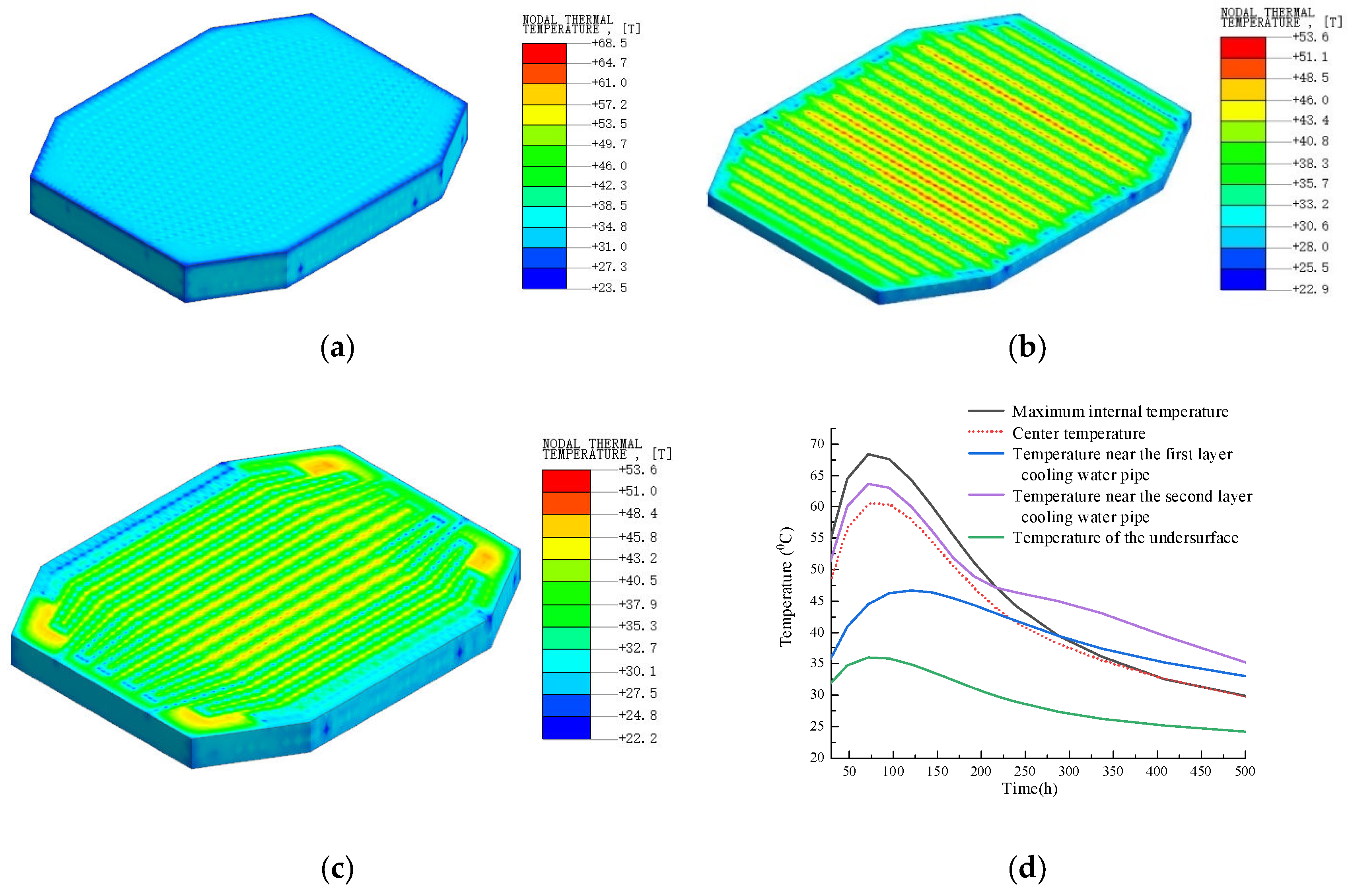
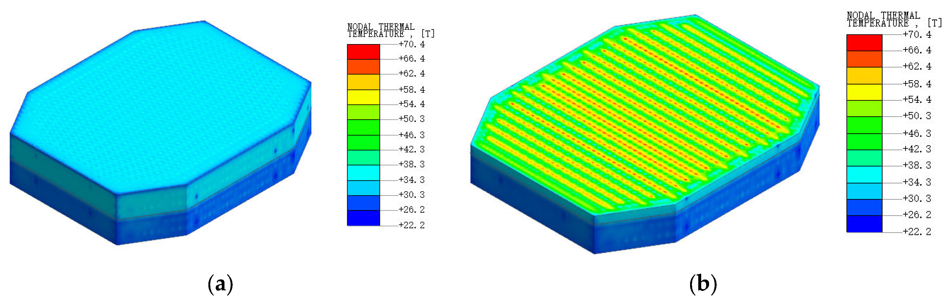
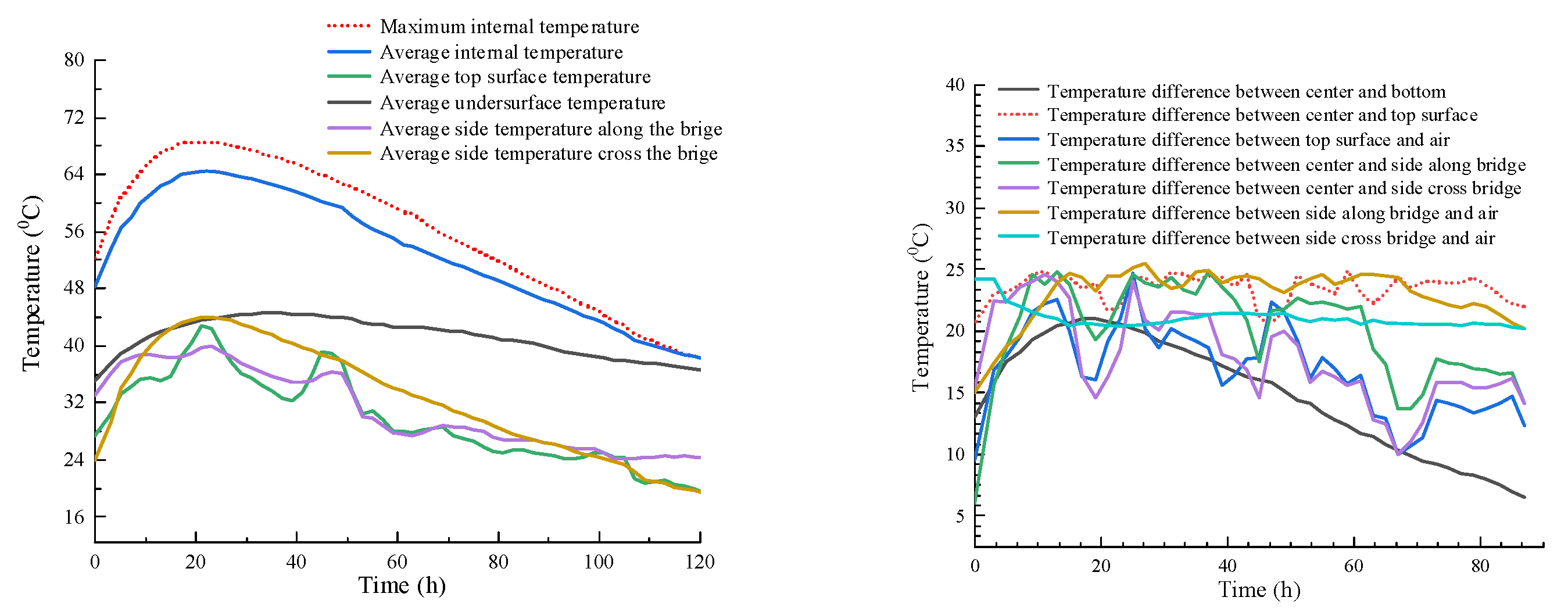
4.3.1. Temperature Calculation Result

The foundation slab is poured twice along the height direction. The thickness of each pouring is 2.5 m, and the time interval between two pouring processes is 200 h. The casting process of the pile cap was simulated by Midas/FEA. The concrete is modeled as a block element with 21,992 elements, and the cooling water pipe is modeled as a pipe cooling element (as shown in Figure 7). Influenced by the irregular cold-water pipe routing, the minimum grid edge length of the model is 0.3 m to satisfy the principle that any small, folded segment contains at least two cells. The diameter of the cooling water pipe is 0.045 m, the velocity of water is 1.5 m/s, the inlet water temperature is 20 °C and the convection coefficient is 518 kJ/(m·h·°C). The thermodynamic coefficients of concrete are obtained from the data in Table 2.
Figure 8 shows the distribution characteristics of the internal temperature of the concrete when the first layer is poured. On the third day of pouring, the internal temperature of the concrete in this layer reaches the maximum value of 68.5 °C, but the maximum temperature does not appear near the center of the pouring concrete. This is because the central layer is located in the middle of the upper and lower rows of the cooling water pipes. It can be seen that the arrangement of the cooling water pipes is more effective in reducing the peak temperature of the concrete. However, the temperature gradient between the cooling water pipe and the concrete is large, which may produce a large temperature stress and produce temperature cracks.
Figure 9 shows the stress distribution inside after the first layer of concrete pouring. The concrete of this layer reaches the highest temperature of 70.4 °C on the third day after pouring, which slightly exceeds the temperature control standard. Therefore, it is necessary to adjust the temperature control measures according to the measured temperature data in the field construction. Similar to the first layer of concrete, due to the effect of two rows of cooling water pipes, the highest temperature did not appear near the center of the concrete layer.

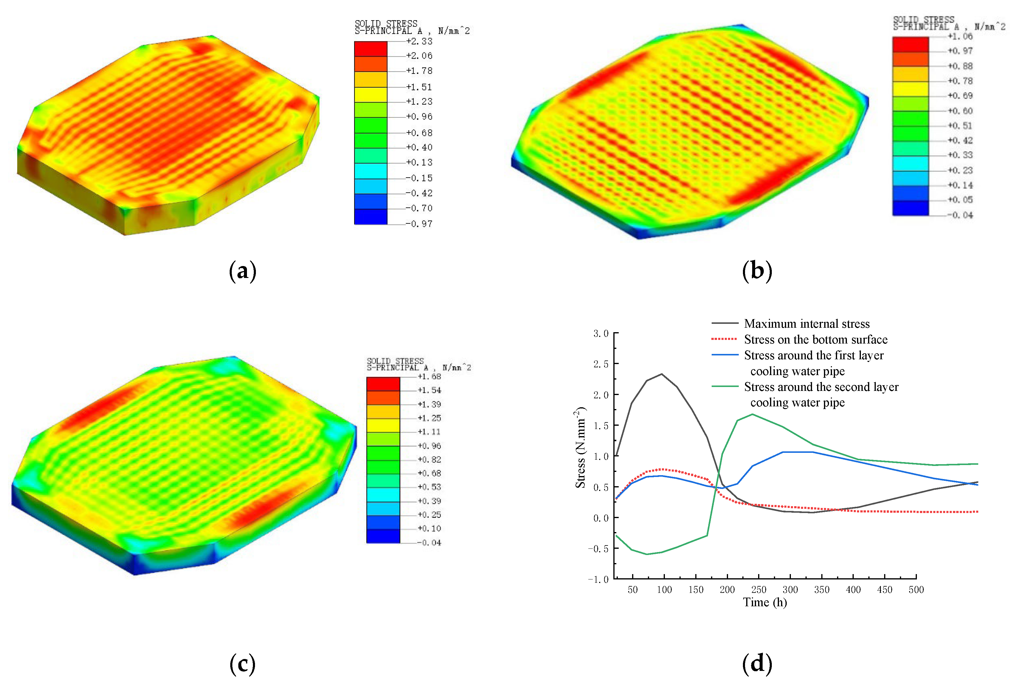
4.3.2. Stress Calculation Results

Figure 10 shows the stress distribution inside the concrete after pouring the first layer of concrete. On the third day after pouring, the stress of this layer of concrete reaches the maximum value of 2.33 MPa, which is greater than the splitting tensile strength test value of 1.5 MPa for 3 days. Therefore, it is necessary to formulate targeted temperature control measures. From the stress distribution map, it can be seen that the larger stress is mainly distributed on the side and upper surface of the pile cap and the contact position between the cooling water pipe and the pile cap. Therefore, when formulating the temperature control scheme, targeted measures are taken. The anti-cracking steel mesh is arranged on the side of the pile cap, the water storage maintenance is adopted on the upper surface of the pile cap and the cooling water temperature is adjusted appropriately in combination with the field monitoring data.
Figure 11 shows the stress distribution inside the concrete after pouring the second layer of concrete. On the fourth day after pouring, the stress of this layer of concrete reaches the maximum value of 2.92 MPa, which is greater than the splitting tensile strength test value of 2.8 MPa for 7 days, so there is a great risk of cracking in pouring concrete. Because the stress distribution of pouring concrete is similar to that of the first layer, the targeted temperature control measures are also the same as those of the first layer. Benefitting from the temperature and stress results obtained from the finite element calculations, the temperature control scheme during casting and molding was formed to avoid excessive temperature gradients, and additional enhancements were installed in localized areas with high stresses.

5. Temperature Monitoring during Cap Construction

5.1. Temperature Control Standards

According to relevant regulations on the temperature control indexes of mass concrete and combined with the actual situation of Fengyi Bridge, the following concrete temperature control standards were determined, as shown in Table 3. After optimizing the concrete mix design and cooling water pipe layout, the comprehensive control standard can be achieved by reducing the temperature of the raw materials before concrete mixing, selecting the concrete pouring time and cooling down the formwork before it enters the mold. For example, the cement is put into the tank in advance to ensure sufficient cooling time and to ensure that the temperature of the cement before mixing is not higher than 60 °C by placing it until it has cooled sufficiently. Moreover, the aggregate temperature is controlled within 28 °C by building a closed silo, storing materials in advance and using a cool water spray. A period of low temperature for concrete construction is selected, and pouring concrete under the condition of a temperature over 30 °C is avoided. The formwork and newly poured concrete are kept away from direct sunlight, and can be sprayed or sprinkled to prevent surface cracking under sunlight.

5.2. Temperature Control Monitoring Program

5.2.1. Temperature Detection Contents and Measuring Instruments

The temperature monitoring of mass concrete during construction includes the measurement of the temperature field inside the concrete and the temperature of the environmental system (atmospheric temperature, inlet and outlet water temperature of the cooling pipe and the flow rate of the cooling water, etc.). As shown in Figure 12, the TW80 concrete wireless thermometer, which can automatically transmit real-time monitoring data to measure the temperature distribution inside concrete, is adopted this project. The effective temperature measurement range is −30~150 °C with a measurement resolution of 0.3 °C. The water temperature and velocity of the cooling water are measured by a building electronic thermometer and portable flow velocity meter, while the atmospheric temperature is measured by a thermometer and hygrometer. In order to obtain the temperature data of the concrete and surrounding environment in time, this project adopts temperature measurement every 2 h for 8 consecutive days in combination with the specific conditions of engineering construction and relevant specification requirements.

5.2.2. Temperature Monitoring of Pile Cap Construction Process

In order to obtain the temperature distribution law of concrete in a more real way, combined with the arrangement principle of temperature measuring points in mass concrete in relevant codes, the temperature measurement area of foundation slab of Fengyi Bridge is laid in the horizontal direction within the plane range of one quarter foundation slab, with three and four measuring points along the axis of the bridge and the cross bridge, and one measuring point in the center. In the vertical direction, five layers of measuring points are arranged along the height range that is 2.5 m thick, and the distance between the edge measuring points and the concrete surface is 50 mm. A total of 40 measuring points are arranged in each layer of pouring concrete. The layout of measuring points in the plane and thickness direction is shown in Figure 13.

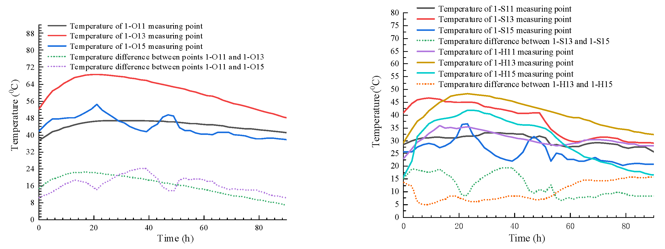
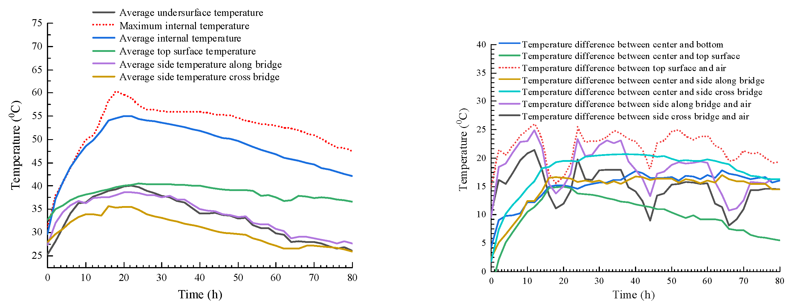
5.3. Analysis of the Detection Results

When concrete is poured over the bottom temperature element, temperature monitoring can begin. Before formal temperature measurement, the installed temperature measuring instrument is checked to ensure the validity of the measured data, as shown in Figure 14. The maximum internal temperature during pouring of the first layer of the cap, as well as the temperature at the top, bottom and center position changing with time are shown in the figure below. It can be seen from Figure 14 that the internal temperature of this layer of concrete reached the maximum of 68.9 degrees within 12 h after pouring. The measured temperature peak value is in good agreement with the numerical simulation results (68.5 °C), but the temperature peak appears much earlier than the numerical simulation results. There are two main reasons for this problem: (1) During the actual construction of the scene, the external temperature is higher, and the molding temperature exceeds 25.6 degrees. (2) There is a certain difference between the heat transfer coefficient used in the numerical calculation and the field maintenance measures. It can be seen from the figure that the temperature difference between the central layer, the surface layer and the side layer is less than 25 degrees, and the maximum temperature difference is 24.6 degrees. In the first 40 h, the temperature difference between the inside and outside of the concrete is large, which is close to the temperature control standard, so the risk of cracking of the concrete is large during this period.
The vertical temperature gradient will have a more important impact on the cracking of the concrete. The central measurement position, as well as the temperature difference between the center of the bridge and the edge of the bridge, are shown in Figure 15. It can be seen from the figure that the temperature difference between the inside and the surface at the center side is small, with a maximum value of 45 degrees, while the temperature difference between the inside and the surface at the edge is large, with a maximum value of 50 degrees for internal–external temperature difference. The excessive temperature difference can easily cause cracking on the surface of the mass concrete. In addition to the optimization of the temperature control scheme, the preventive measure of laying the anti-cracking reinforcement mesh was also proposed to completely avoid this risk. Although the temperature difference between the center and the edge was less than 25 degrees, combined with the numerical analysis results, anti-crack steel mesh was laid on the side of the foundation slab for safety.
After the completion of the first layer of concrete pouring, the second layer of concrete was poured. The internal maximum temperature inside when the concrete pouring of the layer of concrete and the temperature at the bottom surface and the center position are given in Figure 15 (left). Within around 15 h after pouring, the internal temperature of the concrete layer reached the maximum of 68.9 degrees, which was also in good agreement with the numerical simulation result (70.4 °C). However, the temperature peak appeared much earlier than the numerical simulation result. The reason for this problem is similar to the analysis of the first layer, which will not be repeated here.
The temperature difference between the center, surface and side of the concrete pouring layer is also less than 25 degrees, and the maximum temperature difference is 24.6 degrees. In the first 70 h, the temperature difference between inside and outside is relatively large, close to the temperature control standard, and the risk of cracking of the concrete is relatively large.
The temperature difference on the inner surface at the central location of the concrete during pouring of the second layer and at the edge of the bridge along and across the bridge are shown in Figure 16. Similar to the monitoring results of the first layer, the temperature difference between the inside and the surface of the center and the edge is less than 25 degrees. During the pouring of the second layer of concrete, the internal and external temperature difference exceeded 50 degrees, which easily led to surface cracking of the structure. Since the construction period of the pile cap was during the high-temperature season, after adopting measures such as mix ratio design and adding additives, an anti-crack steel mesh was arranged on the sides of the pile cap to reduce surface cracking caused by excessive temperature differences. As shown in Figure 17, the temperature difference between the inside and the surface of the center and the side is small, with a maximum value of degrees, while the temperature difference between the inside and the surface of the edge is large, with a maximum value of degrees. Due to the large temperature gradient inside the coagulation, combined with the results of numerical analysis, the anti-crack steel mesh was also laid on the side of the second layer of concrete on the cap.
The finite element method is used to evaluate the cracking risk of the mass concrete of the cap in advance, and the targeted control measures are taken to add anti-cracking steel mesh on the side of the foundation slab. At the same time, in the temperature monitoring process, the flow rate of cooling water is dynamically adjusted according to the monitoring data. Before the concrete reaches the temperature peak, the maximum flow rate of cooling water is 1.5 m/s, and after reaching the temperature peak, the cooling water velocity is reduced to 1.0 m/s [13]. Under the action of the above comprehensive measures, the surface of the cap after mold removal is smooth and clean, and no obvious harmful temperature cracks are found in the field inspection. Therefore, the temperature control scheme formulated according to the characteristics of the construction environment of the cap has achieved the expected effect and guaranteed the construction quality of mass concrete (as shown in Figure 18). Considering the time interval in which cracks are prone to occur, temperature-controlled anti-cracking monitoring of concrete is continued up to 10 days after the removal of the formwork.

6. Discussion

The research in this paper investigates temperature control, real-time crack detection and control for mass concrete in bridge tower pile caps based on a construction in progress. This project was conducted during the high-temperature season, and utilized both internal cooling and external insulation methods. Based on the temperature of the outgoing water, the core temperature and temperature gradients of the mass concrete as indicators, real-time adjustments were made to the inlet water temperature and flow rate. These measures achieved good results, providing a reference for the formulation of temperature control measures in similar projects. However, due to the numerous factors affecting the temperature stress of concrete, this study still has some shortcomings:
(1) In the process of the layered pouring of mass concrete, the old concrete exerts a restraining effect on the new concrete. This paper only considers the internal restraint effect and ignores the external restraint effect in the analysis.
(2) During the solidification process of mass concrete, the heat of hydration of the concrete involves multi-field coupling heat transfer among the thermal field, flow field, solid structure and atmospheric environment. This paper only studied the fluid–structure coupling effect within the concrete body caused by the heat dissipation of the cooling water pipes, without considering other factors and multi-field coupling effects.

7. Conclusions

Based on the actual characteristics of the project, this paper applies the finite element method to analyze the distribution law of temperature and stress in concrete, and formulates a specific temperature control scheme, which includes optimizing the concrete mixing ratio, laying cooling water pipes, top water storage maintenance and preparing anti-crack reinforcement mesh at the side. Real-time temperature monitoring is carried out for the construction process of the pile cap, and the technical index of temperature control is adjusted dynamically, which achieves a good control effect. Through this research, the following conclusions are drawn:
(1) The internal temperature of concrete usually reaches its peak value in the first 3 days after the pile cap pouring, and the temperature control index is close to the temperature control standard. Temperature cracks occur easily during this period. Therefore, it is necessary to monitor the change in internal temperature of concrete in real time and adjust the temperature control technical index properly with monitoring data to reduce the risk of concrete cracking.
(2) The distribution of the temperature field in the mass concrete of the bearing cap gradually changes from the surface to the interior. The internal temperature is higher, but the temperature gradient is relatively small, while the temperature gradient near the outer surface is larger, which is a dangerous area for cracking. Therefore, under the condition of heat and moisture retention of the surface, an anti-cracking steel mesh can be prepared on the side. In addition to controlling the temperature difference between the center and the top of the concrete, the temperature difference between the center and the outside should also be controlled within 25 degrees.
(3) The mixing ratio of concrete and arrangement of cooling water pipes are optimized by combining the analysis results of temperature and stress during the construction period of the pile cap with the finite method. Fly ash and a water reducer are added to concrete mixtures to reduce temperature peaks. Before reaching the peak temperature, the cooling water pipes are arranged horizontally in layers, and each layer is arranged in zones to independently control the inlet and outlet of each area. The flow rate of the cooling water pipe is 1.5 m/s before concrete reaches the temperature peak, and it drops to 1.0 m/s after reaching the temperature peak.
(4) The concrete and environmental temperature are monitored in real time during the construction of the cap, and the monitoring data are compared with the numerical simulation results. The two temperature peaks agree well, but the time of the temperature peaks is quite different. This is related to the fact that water flow and external environment temperature are both variables in engineering practice, and these factors cannot be considered fully in numerical calculations.
(5) According to the temperature control scheme, the temperature of the mass concrete of the pile cap is monitored, and the control measures are adjusted appropriately according to the monitoring data. The results show that the maximum temperature rise of the cap concrete, the internal and external temperature difference and other indexes comply with the requirements of relevant specifications. The surface of the concrete is smooth after stripping, and no harmful temperature cracks are found in the field inspection. The expected temperature control effect is achieved and the temperature control measures are reasonable.

Author Contributions

Project administration and methodology, S.S.; investigation, Y.Z.; validation, Y.L.; conceptualization, X.X.; funding acquisition and supervision, Z.W.; writing—original draft preparation, Z.L. All authors have read and agreed to the published version of the manuscript.

Funding

The work described in this paper was jointly supported by the science and technology research and development project of China Railway Group Limited (2022-Key project-09) and the Zhengzhou collaborative innovation special project (2023XTCX023).

Data Availability Statement

All data used in this study are available from the corresponding author upon reasonable request.

Conflicts of Interest

Authors Sheng Sun, Yongtao Zhang, Yanjun Lv and Xingshuang Xu were employed by the company China Railway No.3 Engineering Group Co., Ltd. The remaining authors declare that the research was conducted in the absence of any commercial or financial relationships that could be construed as a potential conflict of interest. The authors declare that this study received funding from China Railway Group Limited. The funder was not involved in the study design, collection, analysis, interpretation of data, the writing of this article or the decision to submit it for publication.

Abbreviations

SymbolDescription
a thermal diffusivity
cheating capacity
Ttemperature function
k  k 1   k 2   k p exothermic coefficient
Δ T temperature difference
Q0final hydration heat of cement
Fthe amount of mixed materials
Wthe amount of cement
h i the insulating layer thickness
uwater velocity
r 0   r 1 the inner and the outer diameters of the water pipe
ρ density
τ time
θ adiabatic temperature rise
λ thermal conductivity
β heat release coefficient
γregulation factor
η the diameter ratio of inside and outside cooling water pipe

References

  1. Truman, K.Z.; Petruska, D.J.; Norman, C.D. Creep, shrinkage, and thermal effects on mass concrete structure. J. Eng. Mech. 1991, 117, 1274–1288. [Google Scholar] [CrossRef]
  2. Nilimaa, J.; Hösthagen, A.; Emborg, M. Thermal crack risk of concrete structures: Evaluation of theoretical models for tunnels and bridges. Nord. Concr. Res. 2017, 56, 55–69. [Google Scholar]
  3. Nassiraei, H.; Yara, A. Static Strength of Tubular K-Joints Reinforced with Outer Plates under Axial Loads at Ambient and Fire Conditions. Metals 2023, 13, 1857. [Google Scholar] [CrossRef]
  4. Tajima, K.; Moriizumi, K.; Shirai, N. Numerical calculation mechanics model considering hydration of concrete. In Proceedings of the Fourth International Conference of Fracture Mechanics of Concrete and Concrete Structures, Cachan, France, 28 May–1 June 2001; pp. 107–114. [Google Scholar]
  5. Wilson, E.L. Determination of Temperatures within Mass Concrete Structures; Structural Engineering, University of California San Diego: San Diego, CA, USA, 1968. [Google Scholar]
  6. Wang, J.; Wei, G.; Liu, J.; Chen, J.; Zuo, Y. Measurement and analysis of hydration heat in massive concrete pile cap of a sea-crossing bridge. Bridg. Constr. 2020, 50, 25–31. [Google Scholar]
  7. Wen, D.; Zhang, X.; Chen, G. Temperature control and numerical analysis for massive concrete cushion cap of Hai-huang bridge. J. Wuhan Univ. Technol. 2019, 41, 78–83. [Google Scholar]
  8. Liu, S.; Yin, Z. Study on temperature control and crack resistance of mass concrete anchorage in suspension bridge. Vibroeng. Procedia. 2021, 38, 124–128. [Google Scholar] [CrossRef]
  9. Mardmomen, S.; Chen, H.-L. Prediction of the early age thermal behavior of mass concrete containing SCMs using ANSYS. J. Therm. Anal. Calorim. 2023, 148, 7899–7917. [Google Scholar] [CrossRef]
  10. Qin, F.; Fan, F.; Li, Z.; Qian, H.; Jin, X. Thermal simulation of hydration heat in slab of taishan nuclear power plant unit 2. Comput. Civ. Build. Eng. 2014, 1214–1221. [Google Scholar] [CrossRef]
  11. Zhang, Z.; Wang, K.; Li, Y.-L.; Zhang, W.-M. Study of influential factors of hydration heat and surface cracking resistance of concrete pier in construction. Bridg. Constr. 2015, 45, 65–70. [Google Scholar]
  12. Zou, P.; Chang, H.-J.; Wang, F.; Cai, Y.-L.; Zhang, Z.; Zhao, Z.; Lv, Z.-D. Effect of steam curing scheme on the early-age temperature field of a prefabricated concrete T-beam. Case Stud. Constr. Mater. 2024, 20, e02787. [Google Scholar] [CrossRef]
  13. He, Y.; He, J.; Yu, P.; Zhang, B.; Fu, X. Study on temperature control of mass concrete for tower pile cap. J. Railw. Sci. Eng. 2020, 17, 372–378. [Google Scholar]
  14. Wang, Q.; Chen, C.; Hu, Z.; Li, Y.; Wu, J. Engineering measurement and numerical simulation of hydration heat temperature field of mass concrete of beam bearing platform. Concrete 2020, 371, 139–143+147. [Google Scholar]
  15. Liu, X.; Zhang, C.; Chang, X.; Zhou, W.; Cheng, Y.; Duan, Y. Precise simulation analysis of the thermal field in massconcrete with a pipe water cooling system. Appl. Therm. Eng. 2015, 78, 449–459. [Google Scholar] [CrossRef]
  16. Zhu, B. Theoretical solution of the temperature field in the construction lift of concrete dam under the simultaneous action of pipe cooling and natural cooling from the lift surface. Water Resour. Hydropower. Eng. 2010, 41, 27–28. [Google Scholar]
  17. Yang, H.; Liu, J. Study on the hydration heat temperature field of mass concrete. and the application of key construction technologies for a certain cable stayed bridge cap. Highw. Eng. 2018, 43, 152–156. [Google Scholar]
  18. Lu, Z.; Wang, X. Research on temperature control of mass concrete cushion cap considering water pipe cooling. J. Railw. Sci. Eng. 2015, 12, 1172–1178. [Google Scholar]
  19. Si, Z.; Wang, S.; Wang, Z.; Xi, L. Simulation analysis of mass concrete pipe cooling based on heat flow coupling algorithm. J. Xi’an Univ. Technol. 2017, 33, 270–275. [Google Scholar]
  20. Geng, M.; Lin, E.; Lv, J.; Fu, B. Hydration heat analysis and temperature control of mass concrete pile cap. Concrete 2021, 9, 50–55. [Google Scholar]
  21. Gu, G.; Xu, W.; Wu, Y.; Jia, Y.; Zhou, B. Optimization of temperature control technology for water pipe cooling of mass concrete. Concrete 2021, 11, 141–145. [Google Scholar]
  22. Zhang, B.; Song, S.; Qian, Y.; Liu, Y. Research on temperature control of mass concrete construction of bridge foundation. J. Liaoning Technol. Univ. 2017, 36, 614–618. [Google Scholar]
  23. Li, Z.; He, J.; Yu, P. Temperature and stress field monitoring and finite element analysis of mass concrete of cable tower cushion cap. J. Railw. Sci. Eng. 2020, 17, 2892–2900. [Google Scholar]
  24. Sun, Z.; Tian, J.; Shi, Q.; Liu, W.; Chen, H.; Xu, Q.; Zhang, B. Finite element simulation of inside-outside temperature gradient and thermal stress for abutment mass concrete. J. Traffic. Transp. Eng. 2016, 16, 18–26+36. [Google Scholar]
  25. Miao, S.; Cong, Q.; Ren, F.; Fang, W. Study on hydration heat simulation of mass concrete based on ANSYS. Sichuan Build. Sci. Res. 2009, 35, 194–197. [Google Scholar]
  26. Yuan, G.; Huang, F.; Shen, H.; Gao, P. Study on hydration heat temperature field and thermal stress during mass concrete construction. Concrete 2005, 2, 86–88. [Google Scholar]
  27. Yan, H.; Li, D.; Zhou, H. Hydration heat analysis and crack control of large baseplate. Ind. Archit. 2005, 35, 862–866+871. [Google Scholar]
  28. Wan, H.; Tan, Z. Anti-crack construction technology of mass concrete for main bridge cap of south dongting super large bridge. J. China Foreign Highw. 2017, 37, 141–144. [Google Scholar]
  29. Xu, W.; Yan, Z.; Zhang, S.; Liu, J. Technique of controlling temperature field and concrete expansion to limit cracking in pylons of main navigational channel bridge of hutong changjiang river bridge. Bridg. Constr. 2020, 50, 44–49. [Google Scholar]
  30. Li, J.; Wang, Y. Study on dynamic curing design of pile cap massive concrete of Shanghai-Nantong Yangtze river bridge. Railw. Stand. Des. 2016, 60, 93–99. [Google Scholar]
  31. Qin, Y.; Zhang, Q.; Yu, Y. Temperature control techniques for massive concrete of intermediate pylon pile cap of pingtang bridge. World Bridg. 2018, 46, 30–34. [Google Scholar]
  32. Van Tran, M.; Chau, V.N.; Nguyen, P.H. Prediction and control of temperature rise of massive reinforced concrete transfer slab with embedded cooling pipe. Case Stud. Constr. Mater. 2022, 18, e01817. [Google Scholar] [CrossRef]
  33. Matallah, M.; Taibi, A.; Chimoto, T.; Maradzika, F. Mesoscale investigation of mass concrete temperature control systems and their consequences on concrete mechanical behaviour. Frat. Integrita Strutt. 2022, 16, 416–437. [Google Scholar] [CrossRef]
  34. Ouyang, J.; Chen, X.; Huangfu, Z.; Lu, C.; Huang, D.; Li, Y. Application of distributed temperature sensing for cracking control of mass concrete. Constr. Build. Mater. 2019, 197, 778–791. [Google Scholar] [CrossRef]
  35. Singh, P.R.; Rai, D.C. Effect of piped water cooling on thermal stress in mass concrete at early ages. J. Eng. Mech. 2018, 144, 1–11. [Google Scholar] [CrossRef]
  36. Li, S.-S.; Zheng, J.-Y.; Zhang, F.-J.; Li, H.-M.; Jia, M.-X.; Liu, Z.-J.; Chen, A.-J.; Xie, W. Prediction of shear strength for steel-fiber high-strength concrete corbels with the softened strut-and-tie model. Buildings 2023, 13, 1107. [Google Scholar] [CrossRef]
  37. Deng, N.; Yu, M.; Yao, X. Intelligent active correction technology and application of tower displacement in arch bridge cable lifting construction. Appl. Sci. 2021, 11, 9808. [Google Scholar] [CrossRef]
  38. Yue, Z.; Ding, Y.; Zhao, H.; Wang, Z. Case study of deep learning model of temperature-induced deflection of a cable-stayed bridge driven by data knowledge. Symmetry 2021, 13, 2293. [Google Scholar] [CrossRef]
  39. Zeng, Y.; Zheng, H.; Jiang, Y.; Ran, J.; He, X. Modal analysis of a steel truss girder cable-stayed bridge with single tower and single cable plane. Appl. Sci. 2022, 12, 7627. [Google Scholar] [CrossRef]
  40. Yao, S.; Peng, B.; Wang, L.; Chen, H. Structural performance and reasonable cross-ratio of cross-cable multi-tower cable-stayed bridges. Building 2022, 12, 764. [Google Scholar] [CrossRef]
  41. Tawfik, T.A.; Kamal, A.H.; Faried, A.S. Assessment of the properties of concrete containing artificial green geopolymer aggregates by cold bonding pelletization process. Environ. Sci. Pollut. Res. Int. 2024, 31, 27329–27344. [Google Scholar] [CrossRef]
  42. Li, Y.; Xu, W.; Zhu, J.; Yang, L. Effect of fly ash content on the performance of hardened cement-based materials suffered from high temperatures. Case Stud. Constr. Mater. 2024, 20, e03217. [Google Scholar] [CrossRef]
  43. Mahmoud, H.A.; Tawfik, T.A.; El-razik, M.M.A.; Faried, A.S. Mechanical and acoustic absorption properties of lightweight fly ash/slag-based geopolymer concrete with various aggregates. Ceram. Int. 2023, 49, 21142–21154. [Google Scholar] [CrossRef]
  44. Zhu, Z.; Qiang, S.; Chen, W. A new method solving the temperature field of concrete around cooling pipes. Comput. Concr. 2013, 11, 441–462. [Google Scholar] [CrossRef]
  45. Zhang, H. Construction technology of 3.5m mmass raft concrete for super high-rise tower under high temperature environment. Build. Technol. 2024, 55, 1737–1742. [Google Scholar]
  46. Wang, H. Research on anti cracking technology of mass concrete for main structure of bangladesh river bottom tunnel project. China’s High-Tech. 2022, 22, 120–122. [Google Scholar]
Figure 1. Schematic diagram of Fengyi Bridge (unit: cm).
Buildings 14 03112 g001
Figure 2. The pile caps and the underneath piles (unit: cm). (a) Side view of P1 and P3 (b) side view of P2 (c) top view of the cap at P1 and P3 (d) top view of the cap at P2.
Buildings 14 03112 g002
Figure 3. Temperature control flowchart.
Buildings 14 03112 g003
Figure 4. Layout of cooling water pipes (unit: cm). (a) Vertical layout, (b) horizontal layout, and (c) horizontal layout.
Buildings 14 03112 g004
Figure 5. Boundary conditions applied to different elements of the bridge cap. (a) Boundary condition #1 and (b) boundary condition #2.
Buildings 14 03112 g005
Figure 6. Different boundary conditions. (a) heat transfer path from concrete to water pipe and (b) calculated cross-section along the direction of flow.
Buildings 14 03112 g006
Figure 7. FEM model of the bridge cap and the cooling pipes. (a) Modeling the bridge cap and (b) the distribution of cooling pipes.
Buildings 14 03112 g007
Figure 8. The internal temperature of the first concrete layer. (a) Temperature of the first casting, (b) temperature at the height of the layer 1 water pipe, (c) temperature at the height of the layer 2 water pipe, and (d) temperature variation curves.
Buildings 14 03112 g008
Figure 9. The internal temperature of second concrete layer. (a) Temperature of the second casting, (b) temperature at the height of the layer 3 water pipe, (c) temperature at the height of the layer 4 water pipe, and (d) temperature variation curves.
Buildings 14 03112 g009aBuildings 14 03112 g009b
Figure 10. The stress distribution of the first concrete layer. (a) The internal stress distribution of the first concrete layer, (b) the stress at the height of the layer 1 water pipe, (c) the stress at the height of the layer 2 water pipe, and (d) stress variation curves.
Buildings 14 03112 g010
Figure 11. The stress distribution of the second concrete layer. (a) The internal stress distribution of the second concrete layer, (b) the stress at the height of the layer 3 water pipe, (c) the stress at the height of the layer 4 water pipe, and (d) stress variation curves.
Buildings 14 03112 g011
Figure 12. TW80 concrete wireless thermometer.
Buildings 14 03112 g012
Figure 13. The size of the bridge cap and the layout of measuring points (unit: mm). (a) The layout of the measurement points, (b) the measurement points along the transverse bridge, (c) the measurement points along the longitudinal bridge, and (d) the measurement points along the height direction.
Buildings 14 03112 g013
Figure 14. The temperature curves of the first concrete layer.
Buildings 14 03112 g014
Figure 15. The temperature difference curves of the first concrete layer.
Buildings 14 03112 g015
Figure 16. The temperature curves of the second concrete layer.
Buildings 14 03112 g016
Figure 17. The temperature difference curves of the second concrete layer.
Buildings 14 03112 g017
Figure 18. The surface of mass concrete after casting.
Buildings 14 03112 g018
Table 1. List of raw material selection.
Project NameMain Pier Cap of Fengyi Bridge C40 Concrete Mix Design
Material nameTypeTechnical indicators
Raw materialsCementJidong low-alkali P·O 42.5 Cement
Fly ashGrade Ι
mineral powderOrdinary mineral powderSpecific surface 500 m2/kg
SandMedium sandFineness modulus 2.6~2.8
Gravel Continuous grading 5~25 mm
Water-reducing agentPolycarboxylic acid high-efficiency water-reducing agent
Proportions of C40 concrete mix (kg/m3)CementFly ashMineral powderSandGravelWaterWater-reducing agent
240809075010701538.2
Table 2. Summary of calculation parameters of cap concrete.
Mechanical PropertiesConcrete
Density(kg/m3)2390.1
Coefficient of linear expansion (1/T)1 × 10−5
Poisson’s ratio0.2
Specific heat capacity (kJ/(kg°C))1.0
Pyroconductivity (kJ/(m·h·°C)10
Construction season
Average temperature during construction23
Temperature of concrete entering mold (°C)26
Adiabatic heating (°C)42
7-day tensile strength (MPa)2.8
28-day elastic modulus (N/mm2)3.25 × 104
Table 3. Temperature control standard of cap.
Serial NumberTemperature Control ItemControl StandardBasis
1Pouring temperature of concrete≤26 °CConstruction conditions and calculation results of temperature control
2Maximum internal temperature
of concrete
≤65 °C<<Code for construction of mass concrete>> [45]
<<code for construction of concrete structures>> [45]; calculation results of temperature control
3Temperature difference between inside and outside of concrete
(including equivalent temperature
of concrete shrinkage)
≤20 °C
4Cooling rate insde casting concrete≤2.0 °C/d<<Technical code for construction of highway bridges and culverts>> [46]
5Temperature difference between surface and atmosphere of
pouring concrete
≤20 °C
6Temperature difference between inlet and outlet of cooling water≤10 °C<<Technical specification for temperature crack control of mass concrete in water transport engineering>> [46]
7The temperature difference between the cooling water and the inside concrete when the water is first supplied or resupplied
after interruption
≤25 °C
8Temperature difference between curing water and concrete surface≤15 °C
Disclaimer/Publisher’s Note: The statements, opinions and data contained in all publications are solely those of the individual author(s) and contributor(s) and not of MDPI and/or the editor(s). MDPI and/or the editor(s) disclaim responsibility for any injury to people or property resulting from any ideas, methods, instructions or products referred to in the content.

