Article

Thermo-Mechanical Coupling Load Transfer Method of Energy Pile Based on Hyperbolic Tangent Model

1
Hunan Provincial Key Laboratory of Intelligent Protection and Utilization Technology in Masonry Artifacts, Hunan University of Science and Engineering, Yongzhou 425199, China
2
Faculty of Engineering, China University of Geosciences, Wuhan 430074, China
3
College of Civil Engineering and Architecture, Xinjiang University, Urumqi 830047, China
4
Zhoushan Putuo Qidi Marine Technology Industry Research Institute, Zhoushan 316199, China
*
Author to whom correspondence should be addressed.
Buildings 2024, 14(10), 3190; https://doi.org/10.3390/buildings14103190
Submission received: 12 September 2024 / Revised: 23 September 2024 / Accepted: 3 October 2024 / Published: 7 October 2024

Abstract

:
By employing the hyperbolic tangent model of load transfer (LT), this paper establishes the thermo-mechanical (TM) coupling load transfer analysis approach for an energy pile (EP). By incorporating the control condition of the unbalance force at the null point, the method for determining the null point considering the temperature effect is enhanced. The viability of the presented method is validated through the measured outcomes from model experiments of energy piles. A parametric investigation is conducted to explore the impact of the soil shear strength parameters, upper load, temperature variation, head stiffness, and radial expansion on the axial force, strain, and displacement of the energy pile under thermo-mechanical coupling. The results suggest that the locations of the null point and the maximum axial force are dependent on the constraint boundary conditions of the pile side and the two ends. When the stiffness of the pile top increases, axial stress and displacement increase, while strain decreases. An increase in the drained friction angle leads to an increase in axial stress under thermal-load coupling, but strain and displacement decline. The radial expansion has a negligible influence on the thermo-mechanical interaction between the pile and the soil.

1. Introduction

Energy piles originate from the technology of ground source heat pumps, possessing the dual functions of bearing and heat exchange. In comparison with traditional borehole heat exchangers, they have advantages like high heat transfer efficiency, cost savings, utilization of underground space resources, and lower carbon emissions [1,2,3]. As a green building foundation that promotes energy conservation and environmental protection, EPs have demonstrated promising application prospects in engineering practice [4,5,6,7,8,9,10,11,12,13,14].
The geotechnical engineering design of EPs should consider the additional stress and deformation caused by temperature variations, which consequently affect the bearing characteristics of EPs [6,9]. A large number of scholars have carried out studies on the bearing characteristics of EPs through field tests and theoretical analysis. Researchers such as Laloui et al. [2], Brandl [3], Bourne-Webb et al. [4], Lu et al. [15], and Sutman et al. [16] have carried out in situ tests on EPs. Knellwolf et al. [17], Ouyang et al. [18], Guo et al. [19], and Luo et al. [20] further undertook theoretical research based on the test results of the London and Lausanne experiments. However, research on the bearing characteristics of EPs under TM coupling is relatively scarce, leading to a lack of consensus on the bearing characteristics and LT laws of EPs.
The existing theoretical methods for analyzing the TM properties of EPs are primarily founded on the principles of LT. Knellwolf et al. [17] were the first to incorporate the LT method into the analysis of the bearing characteristics of EPs and employed a three-segment model to depict the pile–soil interaction under TM coupling. Considering the ultimate side frictional resistance brought out by the radial expansion of the pile body due to temperature effects, Plaseied [21] adopted a hyperbolic model [22] to study the load distribution pattern of EPs under TM coupling. Dong et al. [23,24] made use of an exponential model [25] to investigate the long-term responses of the single-EP and EP groups. Despite the simplicity of the principle of the LT method and the requirement for fewer parameters, there is scarce information regarding the parameter range for describing the shapes of the LT curves at the pile side and the pile end necessary for T analysis under TM coupling, and there are still relatively few LT models accessible for analysis.
This paper proposes to conduct research on the TM coupling LT analysis of EPs on the basis of the hyperbolic tangent model LT function proposed by Ding [26]. Combined with the model test to calibrate the model parameters, the mechanical behavior of EPs with different model parameters under the coupling of temperature and load is analyzed in detail. Then, the TM coupling LT analysis method for EPs on the basis of the hyperbolic tangent model is established.

2. Hyperbolic Tangent Model for Load Transfer of Energy Piles

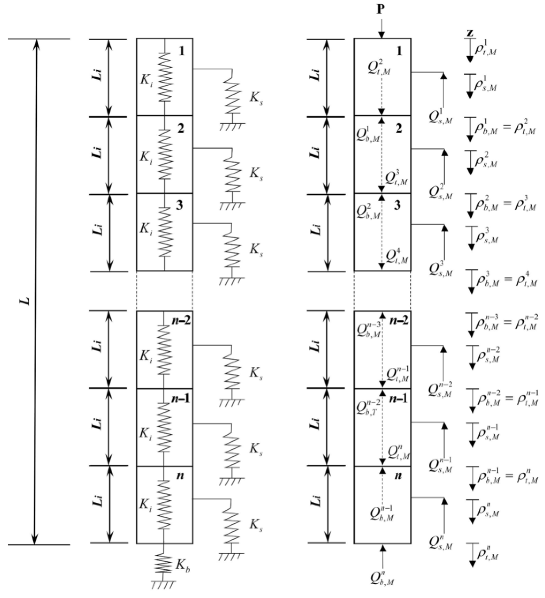
2.1. Calculation Method Considering Load–Temperature Effect

Figure 1 show the schematic diagram of the discretized EP, in which the surrounding and end soils of pile are replaced by corresponding interface springs. Each pile element has a length of L i = L / n , and the stiffness of each element is indicated by means of a spring with a stiffness of K i = E i A i / L i . The relationship between the resistance at the pile side and pile end and the relative displacement of the soil is modeled by virtue of the LT function, where L stands for the length of the pile, A i represents the cross-sectional area of the pile, and E i denotes the elastic modulus of the pile.
The subsequent assumptions are provided throughout the analysis.
(1)
The elastic modulus E and thermal expansion coefficient α T of the pile remain constant, and neither the pile–soil interaction characteristics nor the soil surrounding the pile are affected by the variation of temperature.
(2)
Positive displacement of the pile is determined as downward, with compressive strain and stress within the pile regarded as positive. The upward pile side resistance is also assigned positive values, and a rise in temperature is seen as positive.
(3)
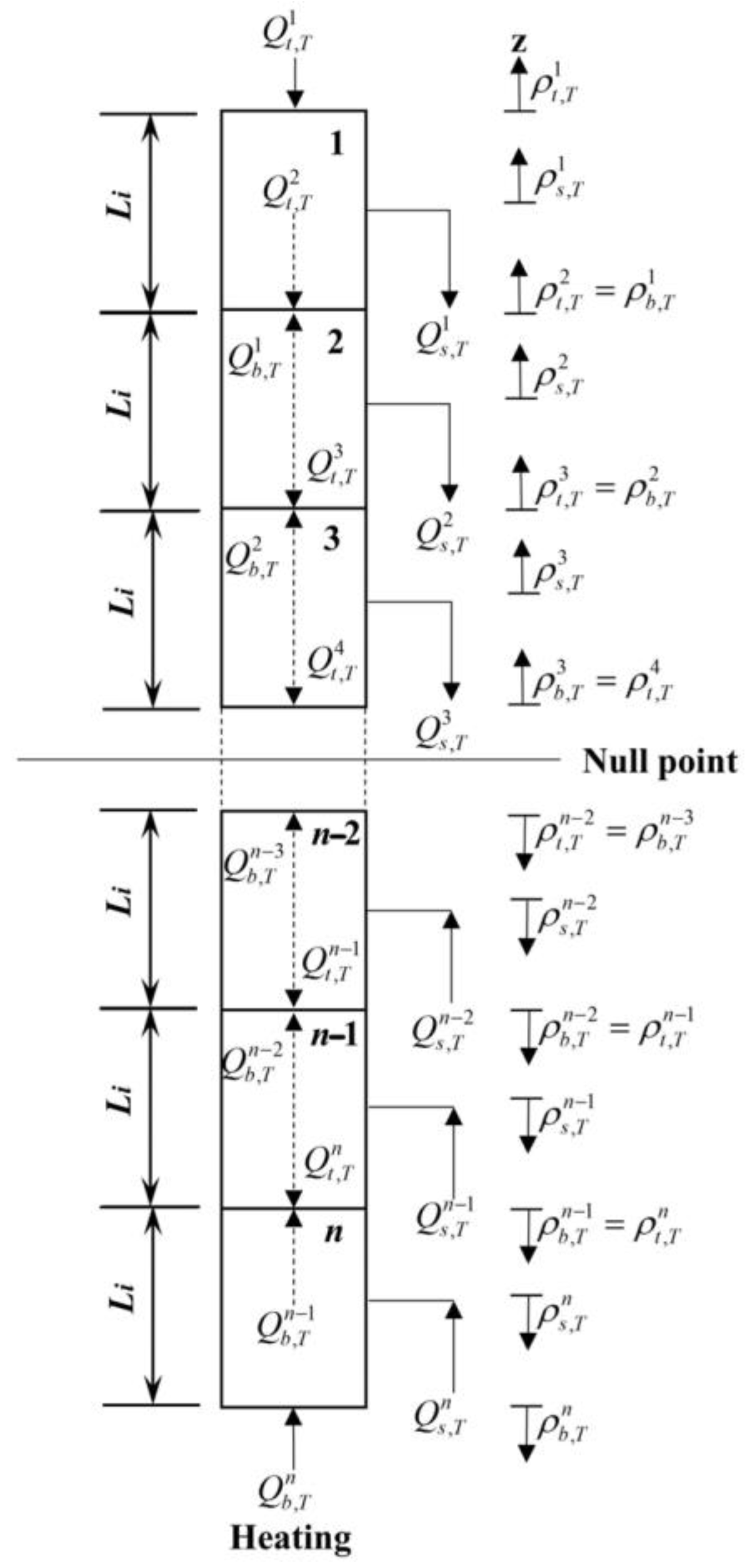
Expansion or contraction around a null point occurs when the pile is heated and cooled [4]. The location of the null point relies on the boundary conditions in the axial direction and the distribution of shear forces on the pile side.
(4)
It is assumed that the ultimate shear resistance grows linearly with depth in the soil layer.
Assuming that the initial displacement at the bottom of the n-th element is ρ b n , the reaction force at the pile end Q b n can be written as:
Q b n = Q b , max · f ( ρ b n ) ,
where Q b , max represents the ultimate bearing capacity at the pile end and f ( ρ b n ) denotes the LT function between the pile and the pile end soil.
The average axial force of the n-th element Q a v e n is given as:
Q a v e n = ( Q b n + Q t , M n ) / 2 ,
where Q t , M n represents the axial force at the top surface of the n-th element, which is assumed to have an initial value of 0.
The compression of the n-th pile shaft Δ M n can be obtained as:
Δ M n = Q a v e n / K i ,
The midpoint displacement of the n-th element ρ s , M n is given as:
ρ s , M n = ρ b n + 1 2 Δ M n ,
The lateral frictional resistance of the n-th element Q s n is expressed as:
Q s n = Q s , max · f ( ρ s , M n ) ,
where Q s , max represents the ultimate lateral frictional resistance of the pile side and f ( ρ s , M n ) denotes the LT function between the pile and the pile side soil.
The axial force at the n-th pile element top Q t , M , n e w n is derived as:
Q t , M , n e w n = Q b n + Q s n ,
In case the disparity between the new and old forces at the current pile element top is not smaller than the predefined tolerance (set as 10−10 in this paper), the new force is employed instead of the old one, and Equations (2)–(6) are recalculated to check for the convergence. This iterative process is repeated, ascending successively until the axial force and relative displacement of the first element are acquired.
The actual load P applied to the pile top may not necessarily be equal to the iteratively obtained axial force at the pile top Q t , M 1 . Utilizing Newton’s method can rapidly determine the pile end displacement, which makes the calculated axial force at the pile top equivalent to the actual load from the upper structure. The calculation formula using Newton’s method is given as:
k sec = Q b , M 1 / Q b , M n ,
ρ b , M , n e w n = ρ b , M n + k sec ( P Q t , M 1 ) ,
where k sec denotes the secant stiffness and ρ b , M , n e w n represents the new displacement at the pile end. In case the disparity between the new and old displacements is not less than the defined tolerance, the same steps as mentioned above are followed for iterative calculation until convergence is attained.
The null point (designated as NP) is characterized as the position where there is no thermal expansion or contraction within the pile when it is supposed that the temperature undergoes uniform changes throughout the pile. The pile is split into n equal elements, each having the position of the null point, as depicted in Figure 2.
To guarantee that the displacement at the null point is zero, the total of the lateral frictional resistance and the axial force at the pile top in the upper segment must be the same as the total of the lateral frictional resistance and the pile end reaction force in the lower segment. Thus, Equation (9) can be employed to determine the position of the null point.
i = 1 N P Q s , T i + Q t , T 1 = i = N P + 1 n Q s , T i + Q b , T n ,
where Q s , T i stands for the lateral frictional resistance for the i-th pile element; Q b , T n represents the resistance at the n-th pile end; Q t , T 1 denotes the constraint force at the pile top, which is linearly related to the thermal displacement at the pile top ρ t , T 1 ; Q t , T 1 = K h ρ t , T 1 , where K h stands for the stiffness coefficient at the pile top, reflecting the constraint effect of the upper structure.
Supposing that the pile undergoes free deformation [17], the thermal strain of the pile element can be expressed as:
Δ T i = L i α T Δ T ,
where Δ T stands for the temperature variation along the pile shaft.
Assuming the position of the null point and setting the number of elements above and below the null point as n 1 and n 2 , respectively, the initial displacements ρ t , M T i , ρ s , M T i , and ρ b , M T i at the top, middle, and bottom of the i-th element below the null point (with positive and negative signs representing warming and cooling effects) can be respectively expressed as:
ρ t , M T i = ρ t , M n 1 + 1 i = n 1 + 1 ρ b , M T i 1 i > n 1 + 1 ,
ρ s , M T i = ρ t , M T i ± Δ T i / 2 ,
ρ b , M T i = ρ t , M T i ± Δ T i ,
Similarly, for the i-th element above the null point, the initial displacements ρ b , M T i , ρ s , M T i , and ρ t , M T i at the bottom, middle, and top can be, respectively, written as:
ρ b , M T i = ρ b , M n 1 i = n 1 ρ t , M T i + 1 i < n 1 ,
ρ s , M T i = ρ b , M T i ± Δ T i / 2 ,
ρ t , M T i = ρ b , M T i ± Δ T i ,
where ρ t , M n 1 + 1 and ρ b , M n 1 stand for the displacements at the bottom of the n 1 + 1 element and the n 1 element under mechanical loading, respectively.
Once the displacements of all elements are obtained, the axial force on each element can be represented by Equations (17)–(21) as:
Q b , M T n = Q b , max · f ( ρ b , M T n ) ,
Q t , M T i = Q b . M T n + j = n i Q s , M T j ,
Q b , M T i = Q t , M T i + 1 ,
σ i = Q t , M T i + Q b , M T i 2 A ,
Δ T a c t u a l i = Δ T i m σ i L i E ,
where Q b , M T denotes the pile end axial force; Q s , M T j represents the lateral resistance of the j-th element ( j = n i ); Q t , M T i and Q b , M T i separately stand for the axial forces at the top and bottom of the i-th element; σ i and Δ T a c t u a l i separately represent the stress and thermal deformation of the i-th element; A is the cross-sectional area of the pile; and m is a coefficient (aimed at preventing non-convergence of deformations caused by significant stiffness at the pile top or bottom).
The actual deformation should iteratively replace the initial deformation (free deformation) in Equations (11)–(21) to obtain the new actual deformation. Repeat this process until the disparity between the new and old actual deformations is smaller than the defined tolerance (taken as 10−10 in this paper).
Once the upper and lower pile elements at the null point converge, the unbalanced force can be obtained as:
F u n b = Q t , M T N P + 1 Q b , M T N P ,
In case the unbalanced force is not less than the defined tolerance (taken as 10−10 in this paper), it shows that the supposed null point is not the real one. To better determine the exact position of the null point, this paper stipulates that if the unbalanced force is positive, it suggests that the actual null point is deeper; if the unbalanced force is negative, it means that the actual null point is shallower. After re-assuming a new null point, repeat Equations (11)–(22) until the unbalanced force is smaller than the defined tolerance. In such a situation, the supposed null point is basically in accordance with the actual null point.
After ascertaining the position of the null point, the distribution patterns of axial force, strain, and displacement under the TM coupling of EPs can be acquired based on the LT analysis in the previous section. The specific calculation procedure is depicted in Figure 3.

2.2. The Transfer Functions

In this paper, both the LT functions for the pile side and pile end are selected using the hyperbolic tangent model proposed by Ding [26]. The LT functions for the pile end and pile side are given in Equations (23) and (24), respectively.
f ( ρ b n ) = a b tanh ( b b ρ b n ) ,
f ( ρ s i ) = a s tanh ( b s ρ s i ) l o a d i n g ρ s i a s + Q s i Q s , max 1 Q s , max Q s i b s u n l o a d i n g ,
where a b and b b are fitting parameters that determine the shape of the LT curve at the pile end, a s and b s determine the shape of the LT curve at the pile side, and Q s i stands for the initial lateral shear resistance after mechanical loading is applied. Murphy and McCartney [27] discovered that the LT curve is insensitive to temperature; thus, it is assumed in this paper that the LT curve is independent of temperature.

2.3. The Ultimate Bearing Capacity of the Pile

The ultimate lateral frictional resistance at a given depth under environmental temperature conditions can be calculated using empirical methods. The β method is based on the effective stress analysis method, which is suitable for both clay and sand [28,29,30,31]. Therefore, this paper utilizes the β method to define the ultimate lateral frictional resistance of the pile, expressed as Equation (25).
Q s , max = β A s σ v ( z ) K 0 tan φ ,
where β is an empirical reduction factor, A s stands for the surface area of the pile side, σ v represents the vertical effective stress at the given depth, K 0 denotes the coefficient for horizontal earth pressure, and φ is the effective friction angle of the soil.
Due to the expansion of the pile into the surrounding soil under temperature loading, soil consolidation occurs, which leads to an increase in the ultimate lateral frictional resistance. Therefore, McCartney and Rosenberg [32] suggested determining the influence of temperature on the ultimate lateral frictional resistance by using the following equation:
Q s , T , max = β A s σ v ( z ) [ K 0 + ( K p K 0 ) K T ] tan φ ,
where K p is the coefficient of passive earth pressure; K T is a reduction factor, which can be determined by Equation (27).
K T = κ α T Δ T D / 2 0.02 L ,
where κ denotes the radial expansion parameter, which is taken as 65 in this paper; [ ( D / 2 ) / ( 0.02 L ) ] is the geometric normalization factor given by Reese et al. [33], where D is the diameter of the pile.
In this paper, the ultimate end bearing resistance is determined under undrained conditions, determined by the following equation.
Q b , max = c u , b A b s c d c N c ,
where c u , b stands for the undrained strength of the soil at the pile end; A b represents the cross-sectional area at the pile end; s c and d c are the shape factors; and N c denotes the bearing capacity factor, taken as 9.0 in this paper. The specific values can be determined according to specific engineering examples.

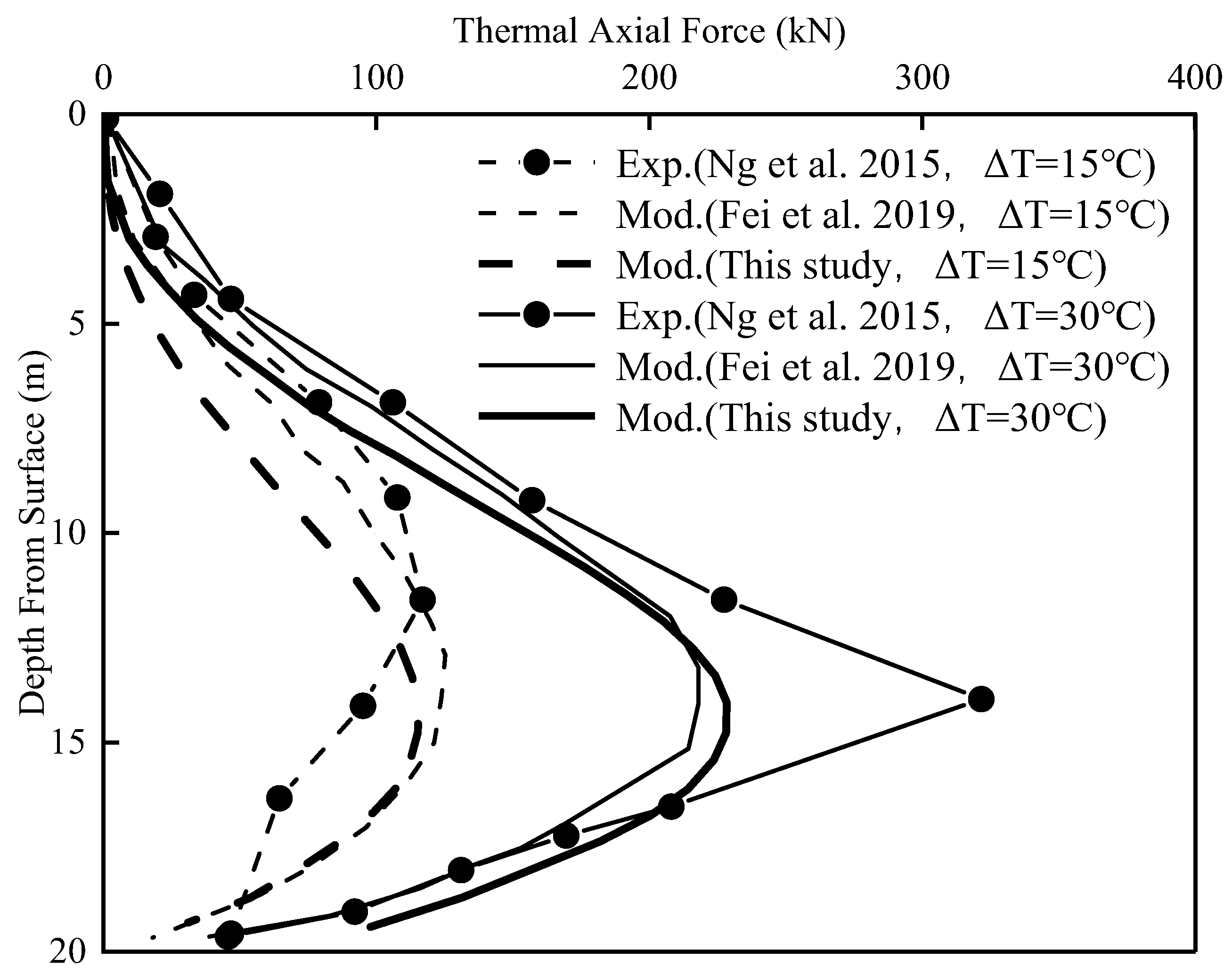
3. Verification of the Proposed Method

To verify the suitability of the hyperbolic tangent model LT method under the TM coupling effect, the 40× g centrifuge tests on EPs in medium-density sand conducted by Ng et al. [34] are selected. The axial force distribution of EPs under TM coupling effects is calculated. Subsequently, the calculated results are compared and analyzed with the measured values.
The prototype pile for the model test has a length of 19.6 m, a diameter of 0.88 m, an elastic modulus of 27.8 GPa, and a thermal expansion coefficient of 2.22 × 10⁻⁵ °C [28,29,35]. The effective unit weight of the soil is 15.4 kN/m3, with an elastic modulus and Poisson’s ratio of 11 MPa and 0.2, respectively. The internal friction angle φ is 31°. In this study, model piles EP15 and EP30 are selected, both with free and without structural loads at the pile head. The temperature rises by 15 °C and 30 °C, respectively. It is assumed that the undrained shear strength at the pile end is 54 kPa with an empirical coefficient β of 0.2. The corresponding LT parameters for the model piles a b , b b , a s , and b s are 0.0007, 1.3, 0.0011, and 0.45, respectively.
Figure 4 presents the axial force distribution along the pile shaft under different temperature increments. It can be noticed that the calculated values from this study are in close accordance with the experimental data. The axial force along the pile shaft shows a pattern of initially rising and then falling, with the null point nearer to the pile end. This phenomenon takes place because the pile head has no boundary constraints, while the pile end can offer stronger constraints, resulting in less downward expansion deformation.

4. Analysis and Discussion

The paper takes a single-layer soil stratum as an example, assuming that the temperature of the pile shaft remains constant with depth [36,37,38]. It is supposed that the ultimate shear strength along the pile shaft is the drained soil property, while the soil at the pile end is regarded as having undrained shear strength. The sensitivity analysis of EP parameters under TM coupling conditions is carried out, and the assumed parameters of the pile and soil are presented in Table 1. The parameters a s , b s , a b , b b , and β of the soil LT model are assumed to be 0.0035, 0.9, 0.002, 0.9, and 0.55, respectively.

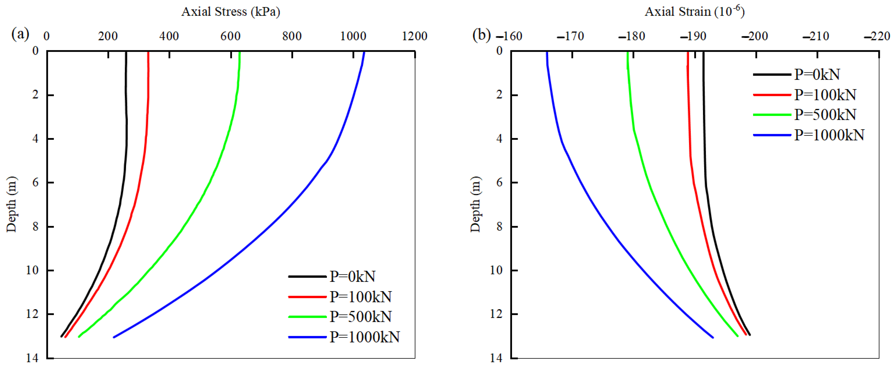
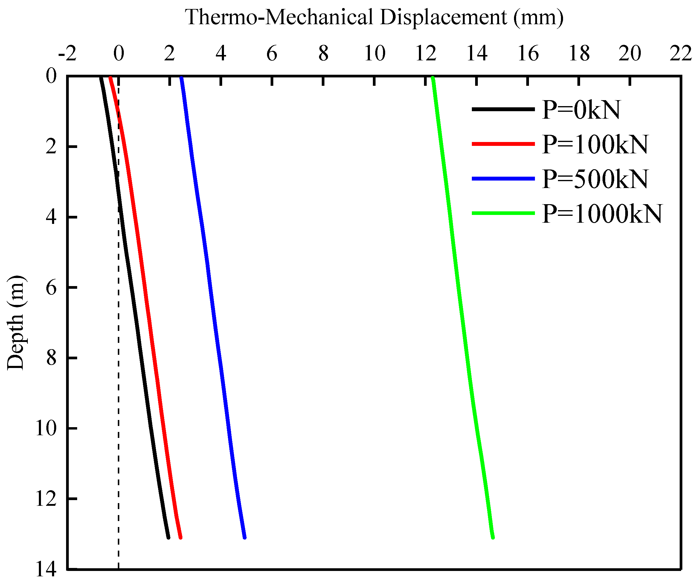
4.1. Influence of Upper Load on the TM Response of Energy Piles

Axial loads of 0, 100, 500, and 1000 kN are applied at the pile head, followed by uniformly applying a temperature change of 20 °C on the EP.
Figure 5 illustrates the axial stress–strain of EPs in drained soil under TM coupling conditions. The higher upper loads lead to increased axial stress and reduced strain, especially notable at the pile head. As the upper loads increase, the additional stress caused by temperature loading gradually reduces. When the upper load is 1000 kN, the additional stress can be largely ignored.
Figure 6 shows the displacement distribution of EPs under TM coupling conditions. It can be found that an increase in upper loads leads to the null point moving upward, possibly because the pile end stiffness decreases with the increase in settlement, while the pile head stiffness remains unchanged. When the load is relatively small, the thermal expansion caused by temperature will cause the pile to undergo vertical tension, resulting in a negative displacement. However, when the load is large, the vertical displacement generated by the load restrains the thermal expansion displacement caused by temperature, and the entire pile exhibits a positive displacement.

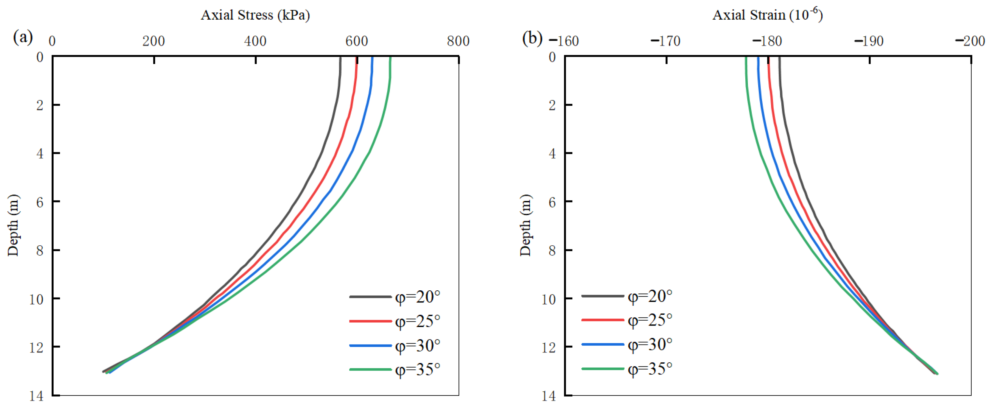
4.2. Influence of Internal Friction Angle on the TM Response of Energy Piles

For drained soils with internal friction angles of 20°, 25°, 30°, and 35°, a 500 kN axial load is initially applied at the pile head, followed by uniformly applying a temperature change of 20 °C on the EP.
The axial stress and strain of EPs in drained soil under varying internal friction angles are depicted in Figure 7. It is clear that with an increase in the internal friction angle, the axial stress rises while the strain drops, particularly notably at the pile head. This phenomenon is due to the increase in lateral frictional resistance with the increase in the internal friction angle.
Figure 8 presents the TM displacement distribution of EPs at different internal friction angles. The results indicate that displacement reduces as the drained internal friction angle increases, and when the internal friction angle is large, this effect can be considered negligible.

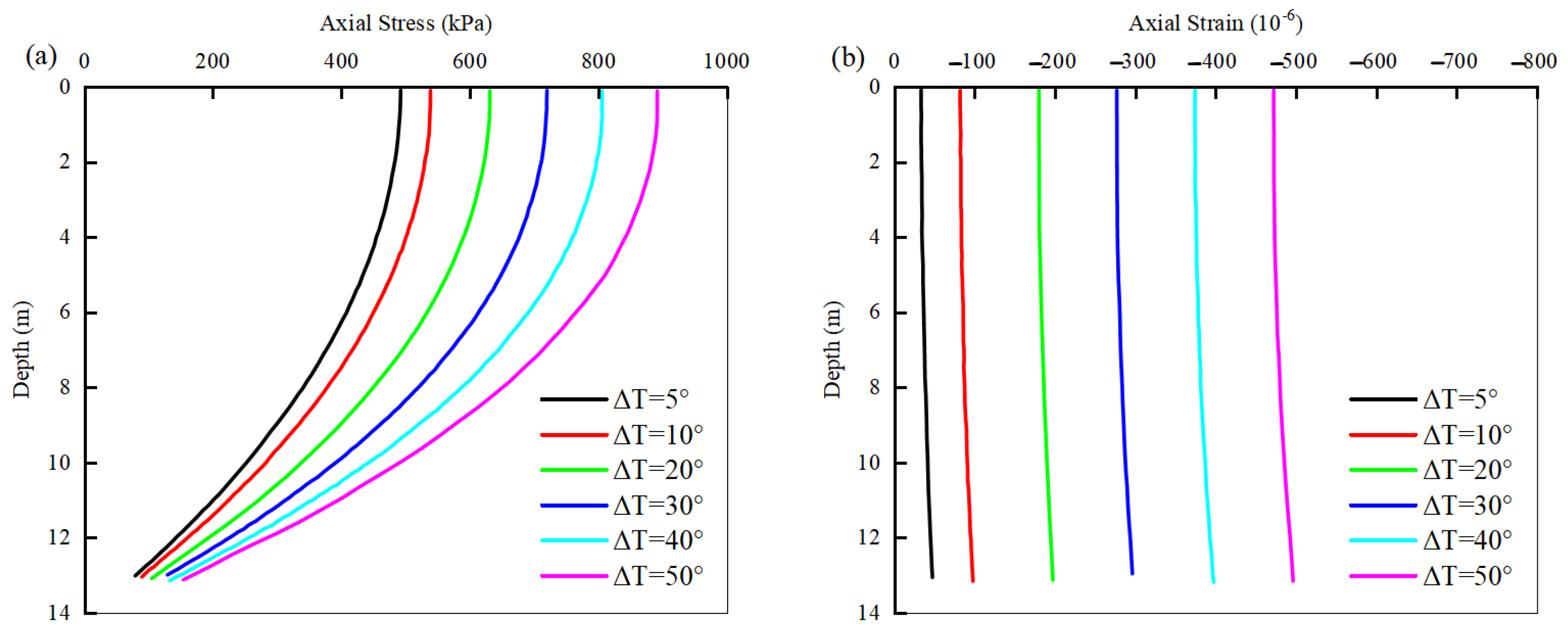
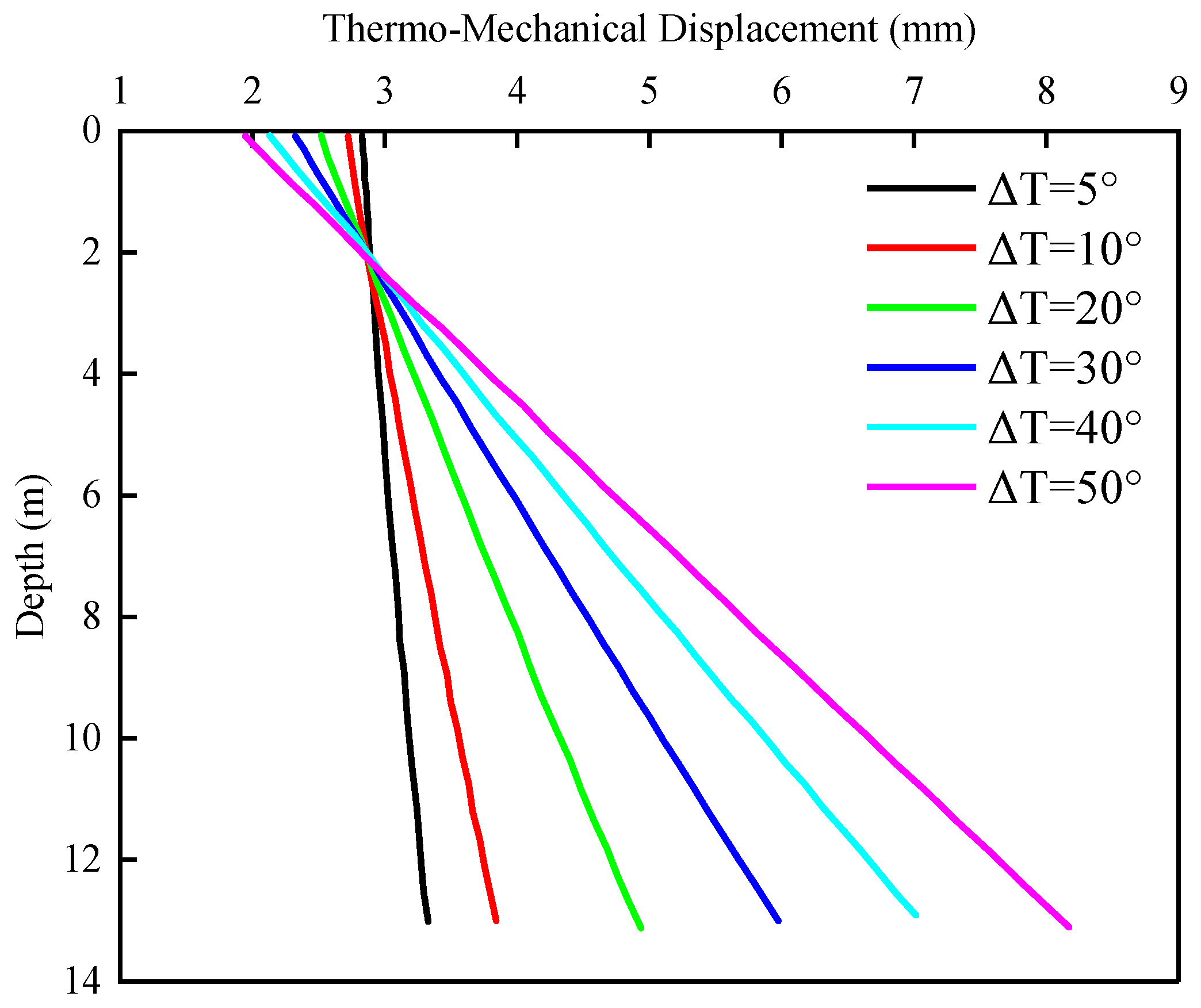
4.3. Influence of Temperature on the TM Response of Energy Piles

A 500 kN axial load is first applied at the pile head; then, the EPs is uniformly subjected to temperature changes of 5 °C, 10 °C, 20 °C, 30 °C, 40 °C, and 50 °C.
The TM axial stress and strain of EPs in drained soil at different temperatures are shown in Figure 9. It can be seen that with the increasing temperature, there is a linear increase in axial stress, with more obvious effects at the pile head than at the pile end. Similarly, strain linearly increases with the temperature.
Figure 10 illustrates the TM displacement distribution of EPs at different temperatures. The results suggest that temperature changes do not alter the position of the null point. As the temperature rises, the TM displacement of the part below the null point of the EP increases, but the displacement of the part above the null point decreases. This phenomenon happens because the part below the null point is in a loaded condition, while the part above the null point is in an unloaded condition.

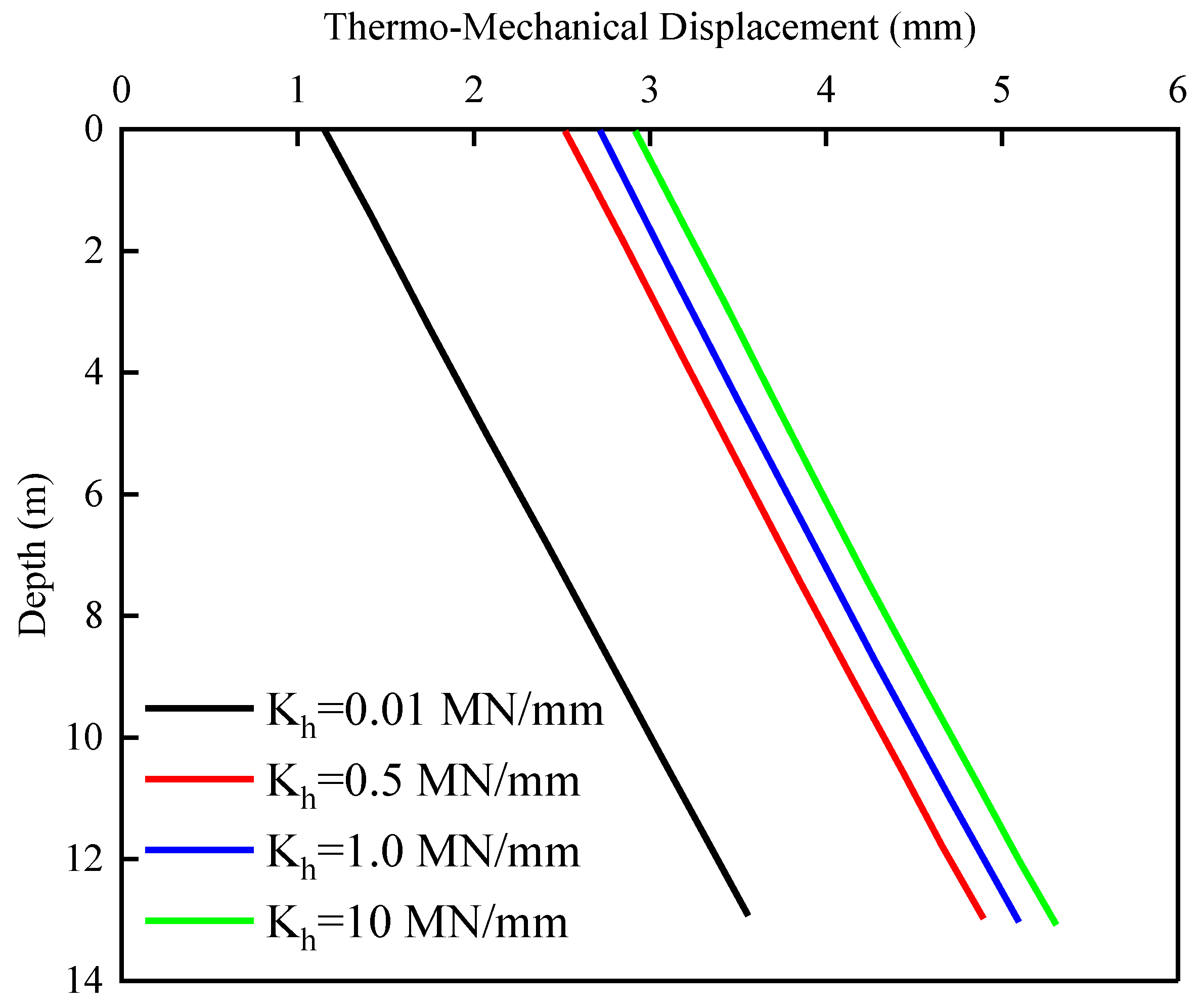
4.4. Influence of Pile Head Stiffness on the TM Response of Energy Piles

First, a 500 axial load is applied at the pile head; then, a temperature change of 20 °C is uniformly applied to the EP. Different pile head stiffnesses of 0.01 MN/mm, 0.5 MN/mm, 1.0 MN/mm, and 10 MN/mm are selected to study the TM response of the EP.
The TM axial stress and strain of EPs with different pile head stiffnesses in drained soil are depicted in Figure 11. The axial stress increases with the increase in pile head stiffness. The greater the pile head stiffness, the smaller the stress increment, especially notably at the pile head compared to the pile end. This is because when the pile head stiffness is small, the null point is nearer to the pile end, making the longer part of the pile shaft move upwards, reducing the lateral shear stress and causing a decrease in axial stress. Strain decreases as the pile head stiffness increases, and the reduction is smaller as the pile head stiffness becomes larger. This reduction is more evident at the pile head, as the increased restraint at the pile head leads to a decrease in upward expansion strain.
Figure 12 shows the TM displacement distribution of EPs with different pile head stiffnesses. It can be observed that as the pile head stiffness increases, the downward displacement also grows. This is because the enhanced restraint at the pile head makes the longer part of the pile tend to move downward, leading to larger displacements.

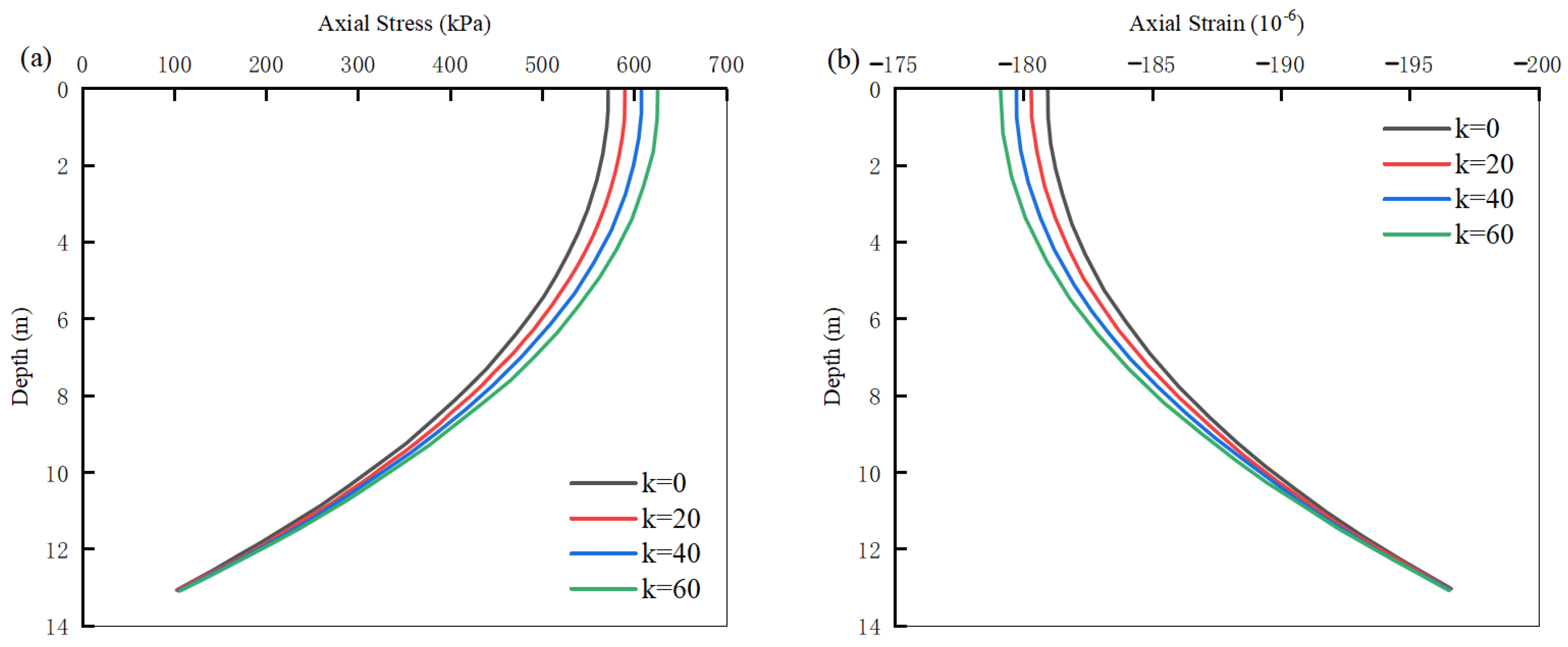
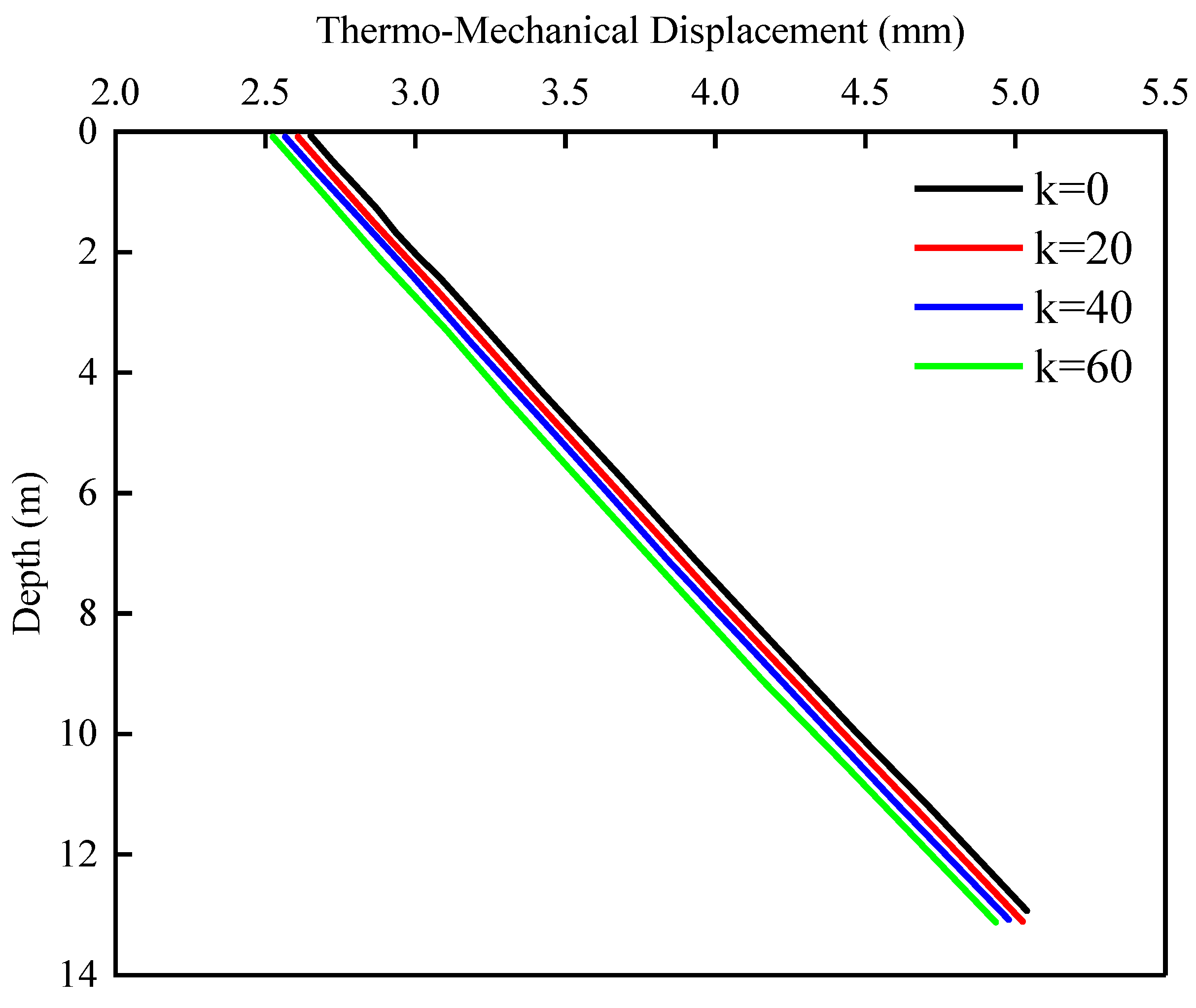
4.5. Influence of Radial Expansion on the TM Response of Energy Piles

A 500 kN axial load is first applied at the pile head, followed by uniformly applying a temperature change of 20 °C to the EP. Different radial expansion parameters κ of 0, 20, 40, and 60 are selected to investigate the TM response of the EP.
The TM axial stress and strain of EPs in drained soil under different radial expansion parameters are given in Figure 13. The axial stress linearly rises with the increase in radial expansion, while strain linearly drops with the increase in radial expansion. The effect of radial expansion on stress and strain at the pile end is insignificant.
Figure 14 illustrates the TM displacement distribution of energy piles under different radial expansion parameters. It can be observed that as the radial expansion parameters gradually increase, the TM displacement linearly decreases.

5. Conclusions

Considering temperature effects based on the hyperbolic tangent model, this paper establishes a TM coupled LT method for EPs to simulate the complex behavior of EPs under temperature–load coupling. The main findings and conclusions are as follows:
(1)
Introducing the control condition of unbalanced forces at the null point improves the method for determining the null point in LT analysis considering temperature effects, making the calculation results more accurate.
(2)
By introducing the method for determining the ultimate bearing capacity of drained soil, the influence of soil shear strength on the TM response of EPs is taken into account. An increase in the drained friction angle leads to an increase in axial stress under thermal-load coupling, while strain and displacement decrease. When the drained friction angle is large, its influence on displacement is restricted.
(3)
An increase in upper loads leads to an increase in axial stress and a decrease in strain under thermal-load coupling, and it also causes the null point to move upward. An increase in temperature leads to a linear increase in axial stress and strain, but it does not alter the position of the null point. The displacement of the pile below the null point increases with temperature, while above the null point, it decreases.
(4)
An increase in pile top stiffness leads to an increase in axial stress and displacement and a decrease in strain. The greater the stiffness, the smaller the magnitude of stress and strain changes, and it also causes the null point to move upward. Increasing the radial expansion parameter leads to a linear increase in axial stress, while strain and displacement decrease linearly. However, it has little impact on the stress at the pile end.
(5)
More research is needed on the effects of variations in the characteristics of the surrounding soil and the pile thermal volume. If EPs are installed in soft clay or expansive clay, significant volume changes and cyclic effects may be encountered. In such situations, LT curves that vary with temperature and loading paths can be employed.

Author Contributions

Conceptualization, M.S., T.W. and W.W.; methodology, M.S., S.W., T.W., Y.X., M.X., Y.D. and W.W.; software, M.S., S.W., T.W., Y.X., Y.D., D.Z. and W.W.; validation, M.S., S.W., T.W., Y.X., M.X., D.Z. and W.W.; formal analysis, M.S., T.W., Y.X., M.X. and W.W.; investigation, M.S., S.W., T.W., Y.X., M.X., Y.D., D.Z. and W.W.; resources, M.X., Y.D., D.Z. and W.W.; data curation, M.S., S.W., T.W., Y.X., D.Z. and W.W.; writing—original draft preparation, M.S., S.W., T.W., Y.X., Y.D. and D.Z.; writing—review and editing, T.W., M.X. and W.W.; visualization, M.S., S.W., Y.X. and W.W.; supervision, T.W. and W.W.; project administration, W.W.; funding acquisition, Y.D., D.Z. and W.W. All authors have read and agreed to the published version of the manuscript.

Funding

This research was funded by the National Natural Science Foundation of China (Grant Nos. 52178371, 52108355, 52308383). The Research Project of Hunan Provincial Key Laboratory of Intelligent Protection and Utilization Technology for Brick and Stone Cultural Relics (Grant No. HUSE-2024-02), the Research Project of Engineering Research Centre of Rock-Soil Drilling & Excavation and Protection, Ministry of Education (Grant No. 202305), the Science and Technology Project of Zhejiang Provincial Communication Department (Grant No. 202305-2) and the Construction Research Founds of Department of Housing and Urban-Rural Development of Zhejiang Province (Grant No. 2021K256) are also acknowledged.

Data Availability Statement

The data presented in this study are available on request from the corresponding author. The data are not publicly available due to privacy and ethical restrictions.

Conflicts of Interest

The authors declare no conflicts of interest.

References

  1. Liu, H.L.; Kong, G.Q.; Wu, H.W. Research progress on energy pile engineering applications and development of PCC energy pile technology. Chin. J. Geotech. Eng. 2014, 36, 176–181. (In Chinese) [Google Scholar]
  2. Laloui, L.; Nuth, M.; Vulliet, L. Experimental and numerical investigations of the behaviour of a heat exchanger pile. Int. J. Numer. Anal. Methods Geomech. 2006, 30, 763–781. [Google Scholar] [CrossRef]
  3. Brandl, H. Energy foundations and other thermo-active ground structures. Géotechnique 2006, 56, 81–122. [Google Scholar] [CrossRef]
  4. Bourne-Webb, P.J.; Amatya, B.; Soga, K.; Amis, T.; Davidson, C.; Payne, P. Energy pile test at Lambeth College, London: Geotechnical and thermodynamic aspects of pile response to heat cycles. Géotechnique 2009, 59, 237–248. [Google Scholar] [CrossRef]
  5. Amatya, B.L.; Soga, K.; Bourne-Webb, P.J.; Amis, T.; Laloui, L. Thermo-mechanical behaviour of energy piles. Géotechnique 2012, 62, 503–519. [Google Scholar] [CrossRef]
  6. Gui, S.Q.; Cheng, X.H. In-situ experimental study on structural response during heat exchange process of energy piles. Chin. J. Geotech. Eng. 2014, 36, 1087–1094. (In Chinese) [Google Scholar]
  7. Peng, H.F.; Kong, G.Q.; Liu, H.L.; Abuel-Naga, H.; Hao, Y.H. Thermo-mechanical behaviour of floating energy pile group in sand. J. Zhejiang Univ. Sci. A (Appl. Phys. Eng.) 2018, 19, 638–649. [Google Scholar] [CrossRef]
  8. Zhang, Y.P.; Ji, H.X.; Liu, H.; El Naggar, M.H.; Jiang, G.S.; Wu, W.B. Initial horizontal dynamic impedance of single anti-toppling helical pile for offshore wind turbines. Ocean Eng. 2024, 306, 118048. [Google Scholar] [CrossRef]
  9. Wu, W.B.; Di, T.Y.; Yang, X.Y.; El Naggar, M.H.; Zhang, Y.P. Revised pile-pile mutual interaction factors for seismic analysis of end-bearing pile groups embedded in saturated stratum. Soil Dyn. Earthq. Eng. 2024, 182, 108745. [Google Scholar] [CrossRef]
  10. Lian, J.; Ding, X.M.; Zhang, L. Shaking table test on seismic response of an accumulation landslide reinforced by pile-plate retaining wall based on the time-frequency analysis method. J. Cent. South Univ. 2023, 30, 1710–1721. [Google Scholar] [CrossRef]
  11. Song, H.B.; Pei, H.F.; Pereira, J.M.; Tang, A.M.; Zhou, C. A simple load transfer method for energy pile groups. Comput. Geotech. 2023, 159, 105483. [Google Scholar] [CrossRef]
  12. Peng, C.; Ding, X.M.; Wang, C.L.; Kong, G.Q.; Wu, D. Thermo-mechanical characteristics of laterally loaded energy piles under multiple heating-cooling cycles in mountain area. J. Energy Storage 2023, 63, 107020. [Google Scholar] [CrossRef]
  13. Zhang, D.X.; Wang, C.L.; Bouazza, A.; Ding, X.M.; Kong, G.Q. Influence of a rigid cap on thermo-mechanical behavior of nonsymmetrical thermally loaded energy pile group in clay. Can. Geotech. J. 2023, 60, 654–668. [Google Scholar] [CrossRef]
  14. Ai, Z.Y.; Ye, J.M. Thermo-mechanical analysis of pipe energy piles in layered cross-isotropic soils. Energy 2023, 277, 127757. [Google Scholar] [CrossRef]
  15. Lu, H.W.; Jiang, G.; Wang, H.; Hong, X.; Shi, C.L.; Gong, H.W.; Liu, W.Q. Field joint test and bearing characteristic analysis of frictional energy pile under load-temperature coupling. Chin. J. Geotech. Eng. 2017, 39, 334–342. (In Chinese) [Google Scholar]
  16. Sutman, M.; Brettmann, T.; Olgun, C.G. Full-scale in-situ tests on energy piles: Head and base-restraining effects on the structural behaviour of three energy piles. Geomech. Energy Environ. 2019, 18, 56–68. [Google Scholar] [CrossRef]
  17. Knellwolf, C.; Peron, H.; Laloui, L. Geotechnical analysis of heat exchanger piles. J. Geotech. Geoenviron. Eng. 2011, 137, 890–902. [Google Scholar] [CrossRef]
  18. Ouyang, Y.; Soga, K.; Leung, Y.F. Numerical back-analysis of energy pile test at Lambeth College, London. In Geo-Frontiers 2011: Advances in Geotechnical Engineering, Proceedings of the Geo-Frontiers Congress 2011, Dallas, TX, USA, 13 March 2011; American Society of Civil Engineers: Reston, VA, USA, 2011; pp. 440–449. [Google Scholar]
  19. Guo, H.R.; Qiao, L.; Li, Y. Research on the bearing performance of energy piles using an improved load-transfer model on pile-soil interface. Rock Soil Mech. 2018, 11, 4042–4052. (In Chinese) [Google Scholar]
  20. Luo, X.Q.; Liu, G.B.; Zheng, Y.D.; Qian, F.; Zhou, M. A load transfer model of energy pile-soil interfaces under temperature variation. Chin. J. Rock Mech. Eng. 2019, 38, 171–179. [Google Scholar]
  21. Plaseied, N. Load-Transfer Analysis of Energy Foundations. Master’s Thesis, University of Colorado at Boulder, Boulder, CO, USA, 2012. [Google Scholar]
  22. Stewart, M.A.; McCartney, J.S. Centrifuge modeling of soil-structure interaction in energy foundations. J. Geotech. Geoenviron. Eng. 2014, 140, 04013044. [Google Scholar] [CrossRef]
  23. Dong, L.L.; Wu, W.B.; Liang, R.Z.; Liu, H.; Mei, G.X.; Yang, Z.J. Long-term responses of energy piles based on exponential model. Chin. J. Rock Mech. Eng. 2021, 40, 629–639. [Google Scholar]
  24. Dong, L.L.; Mei, G.X.; Wu, W.B.; Wang, L.X.; Ruan, H.F. Numerical simulation of working characteristics of energy pile group under thermos-mechanical coupling. Bull. Geol. Sci. Technol. 2021, 40, 326–334. [Google Scholar]
  25. Chen, C.; Leng, W.M.; Yang, Q.; Dong, J.L.; Xu, F.; Ruan, B. Effect of a filter cake on shear behavior of sand-concrete pile interface. J. Cent. South Univ. 2022, 29, 2019–2032. [Google Scholar] [CrossRef]
  26. Ding, Y.Q. Research on Method and Application of Nonlinear Seismic Response Analysis of Site. Master’s Thesis, Chongqing University, Chongqing, China, 2010. (In Chinese). [Google Scholar]
  27. Murphy, K.D.; McCartney, J.S. Thermal borehole shear device. Geotech. Test. J. 2014, 37, 20140009. [Google Scholar] [CrossRef]
  28. Fei, K.; Dai, D.; Hong, W. Simplified analysis method for working characteristics of single energy pile. Rock Soil Mech. 2019, 40, 70–80. (In Chinese) [Google Scholar]
  29. Fei, K.; Ding, S.J.; Qin, H.Y. Analysis of energy pile groups subjected to non-uniform thermal loadings. Undergr. Space 2023, 9, 91–104. [Google Scholar] [CrossRef]
  30. Ding, X.M.; Zhang, D.X.; Bouazza, A.; Wang, C.L.; Kong, G.Q. Thermo-mechanical behaviour of energy piles in overconsolidated clay under various mechanical loading levels and thermal cycles. Renew. Energy 2022, 201, 594–607. [Google Scholar] [CrossRef]
  31. Xing, K.Y.; Lu, H.Z.; Chen, Y.C.; Wang, X.G.; Zhang, K.S.; Wu, W.B. Nonlinear solutions of lateral response for piles under axial and lateral load embedded in layered soils. Bull. Geol. Sci. Technol. 2021, 40, 166–174. [Google Scholar]
  32. McCartney, J.S.; Rosenberg, J.E. Impact of heat exchange on side shear in thermo-active foundations. In Geo-Frontiers 2011: Advances in Geotechnical Engineering, Proceedings of the Geo-Frontiers Congress 2011, Dallas, TX, USA, 13 March 2011; American Society of Civil Engineers: Reston, VA, USA, 2011; pp. 488–498. [Google Scholar]
  33. Reese, L.C.; Isenhower, W.M.; Wang, S.T. Analysis and Design of Shallow and Deep Foundations; John Wiley & Sons: Hoboken, NJ, USA, 2005. [Google Scholar]
  34. Ng, C.W.W.; Shi, C.; Gunawan, A.; Laloui, L.; Liu, H.L. Centrifuge modelling of heating effects on energy pile performance in saturated sand. Can. Geotech. J. 2015, 52, 1045–1057. [Google Scholar] [CrossRef]
  35. Loria, A.F.R.; Gunawan, A.; Shi, C.; Laloui, L.; Ng, C.W.W. Numerical modelling of energy piles in saturated sand subjected to thermo-mechanical loads. Geomech. Energy Environ. 2015, 1, 1–15. [Google Scholar] [CrossRef]
  36. McCartney, J.S.; Rosenberg, J.E.; Sultanova, A. Engineering performance of thermo-active foundations. In GeoTrends: The Progress of Geological and Geotechnical Engineering in Colorado at the Cusp of a New Decade; American Society of Civil Engineers: Reston, VA, USA, 2011; pp. 27–42. [Google Scholar]
  37. Zhu, Y.P.; Chen, G.D. Quantifying thermal strain of steel plate subjected to constant temperature by distributed fiber optic sensors. Intell. Transp. Infrastruct. 2022, 1, liac005. [Google Scholar] [CrossRef]
  38. Xie, J.H.; Wem, M.J.; Tu, Y.; Wu, D.Z.; Liu, K.F.; Tang, K.J. Thermal consolidation of layered saturated soil under time-dependent loadings and heating considering interfacial flow contact resistance effect. Int. J. Numer. Anal. Methods Geomech. 2024, 48, 1123–1159. [Google Scholar] [CrossRef]
Figure 1. Discretized energy pile used in the load transfer analysis.
Buildings 14 03190 g001
Figure 2. Typical foundation schematic of n elements highlighting the location of the null point.
Buildings 14 03190 g002
Figure 3. Flow chart for computational thermomechanical analysis of energy piles.
Buildings 14 03190 g003
Figure 4. Experimental and modeled thermally induced axial forces by Fei et al. [28] and Ng et al. [34].
Buildings 14 03190 g004
Figure 5. Soil–structure interaction behavior of energy pile in drained soils for different upper loads: (a) TM axial stresses; (b) TM axial strains.
Buildings 14 03190 g005
Figure 6. TM displacements distributions for different upper loads.
Buildings 14 03190 g006
Figure 7. Soil–structure interaction behavior of energy pile in drained soils for different internal friction angles: (a) TM axial stresses; (b) TM axial strains.
Buildings 14 03190 g007
Figure 8. TM displacements distributions for different internal friction angles.
Buildings 14 03190 g008
Figure 9. Soil–structure interaction behavior of energy pile in drained soils for different temperatures: (a) TM axial stresses; (b) TM axial strains.
Buildings 14 03190 g009
Figure 10. TM displacement distributions for different temperatures.
Buildings 14 03190 g010
Figure 11. Soil–structure interaction behavior of energy pile in drained soils for different pile head stiffnesses: (a) TM axial stresses; (b) TM axial strains.
Buildings 14 03190 g011
Figure 12. TM displacement distributions for different pile head stiffnesses.
Buildings 14 03190 g012
Figure 13. Soil–structure interaction behavior of energy pile in drained soils for different radial expansions: (a) TM axial stresses; (b) TM axial strains.
Buildings 14 03190 g013
Figure 14. TM displacements distributions for different radial expansions.
Buildings 14 03190 g014
Table 1. Model parameters of the present study.
Model ParametersVariableValue
Length of pileL (m)13.1
Diameter of pileD (m)1.2
Young’s modulus of pileE (GPa)30
Coefficient of thermal expansion of pile α T (°C−1)10−6
Drained friction angle of soil φ (°)30
Unit weight of pilekN/m318
Undrained shear strength at the toekPa54
Disclaimer/Publisher’s Note: The statements, opinions and data contained in all publications are solely those of the individual author(s) and contributor(s) and not of MDPI and/or the editor(s). MDPI and/or the editor(s) disclaim responsibility for any injury to people or property resulting from any ideas, methods, instructions or products referred to in the content.

