Article

In-Plane Mechanical Properties Test of Prefabricated Composite Wall with Light Steel and Tailings Microcrystalline Foamed Plate

1
Tianjin Key Laboratory of Civil Structure Protection and Reinforcement, Tianjin Chengjian University, Tianjin 300384, China
2
Faculty of Architecture, Civil and Transportation Engineering, Beijing University of Technology, Beijing 100124, China
3
Hebei Technology Innovation Center of Green Construction for Building Structures, Tangshan 063210, China
4
China Construction Eighth Engineering Division Co., Ltd., Shanghai 200135, China
5
School of Vocational Education, Chengde Open University, Chengde 067000, China
*
Author to whom correspondence should be addressed.
Buildings 2024, 14(10), 3196; https://doi.org/10.3390/buildings14103196
Submission received: 29 August 2024 / Revised: 25 September 2024 / Accepted: 5 October 2024 / Published: 8 October 2024
(This article belongs to the Special Issue Innovation of Seismic Behavior in Structural Engineering)

Abstract

:
The tailings microcrystalline foamed plate (TMF plate), produced from industrial waste tailings, has limited research regarding its use in high-performance building walls. Its brittleness under stress poses challenges. To improve its mechanical properties, a prefabricated light steel-tailings microcrystalline foamed plate composite wall (LS-TMF composite wall) has been proposed. This LS-TMF composite wall system integrates assembly, sustainability, insulation, and decorative functions, making it a promising market option. To study the in-plane performance of the composite wall, compression and seismic performance tests were conducted. The findings indicate that the light steel keel, steel bar, and TMF plate in the composite wall demonstrated good working performance. Strengthening the TMF plate enhanced the restraint on the light steel keel and improved the composite wall’s compressive performance. Increasing the thickness of the light steel keel further improved the compressive stability. Under horizontal cyclic loading, failure occurred at the light steel keel embedding location. Increasing the strength of the TMF plate was beneficial for the seismic performance of the composite wall. This structural configuration—incorporating light steel keels, TMF plates, and fly ash blocks—enhanced thermal insulation and significantly improved in-plane stress performance. However, the splicing plate structure adversely affected the seismic performance of the composite wall.

1. Introduction

As the world intensifies efforts to combat climate change, achieving carbon peaking and carbon neutrality has become a pressing goal for many nations. The building sector, which accounted for over one-third of global energy-related carbon emissions [1], plays a pivotal role in overall carbon emissions. Consequently, the construction industry holds considerable potential for emission reductions, making it essential in reaching these climate targets.
In recent years, rapid industrialization has led to a sharp rise in industrial waste production, causing severe environmental pollution. Studies project that urban solid waste will reach approximately 3.4 billion tons by 2050 [2]. When left untreated, industrial waste contains large amounts of toxic substances, such as heavy metals and organic pollutants, which can infiltrate ecosystems through soil and water, posing a serious threat to human health [3]. Among these industrial wastes, tailings are among the most prevalent and hazardous. Effectively utilizing industrial waste, particularly tailings, and converting it into valuable resources has become a critical area of research in environmental protection and resource management.
The tailings microcrystalline foamed plate (TMF plate) is an innovative building material made from industrial waste tailings. It is lightweight and offers excellent thermal insulation and fire resistance. The surface layer can be customized into various colored microcrystalline glass decorative layers to meet specific engineering needs. These decorative layers, fused with the insulation layer in a single firing process, create a highly durable exterior wall panel that combines load bearing, thermal insulation, and decorative functions. This product has significant market potential (Figure 1). Through the resourceful conversion of industrial waste, the TMF plate not only reduces environmental pollution but also promotes resource recycling. This process contributes to lowering carbon emissions and supports the achievement of carbon peaking and neutrality [4].
The use of energy-efficient building materials can significantly reduce a building’s energy consumption, thereby lowering carbon emissions. For instance, Llantoy et al. [5] demonstrated that energy-saving materials can cut a building’s power consumption, with insulated cubicles achieving over 20% energy savings compared to uninsulated ones. Ameri et al. [6] pointed out that using lightweight, high-strength materials can reduce the overall weight of building structures, leading to decreased energy demand and operating costs. The TMF plate demonstrates outstanding performance in building energy efficiency, making it an ideal material for thermal insulation in construction due to its exceptional heat-insulating capabilities. Composed primarily of microcrystalline foam glass, the TMF plate has been the subject of extensive research aimed at refining its manufacturing techniques and enhancing its properties. Deng et al. [7] utilized granite tailings as the primary ingredient and employed a combination of silicon carbide (SiC) and manganese dioxide (MnO2) as foaming agents to fabricate TMF plates using the powder sintering technique. Under a sintering temperature of 880 °C, the resulting TMF plates exhibited a thermal conductivity ranging from 0.037 to 0.046 W/(m·K), a bulk density between 0.35 and 0.50 g/cm3, porosity between 85.05% and 88.12%, and compressive strength ranging from 0.46 to 3.11 MPa, thereby demonstrating superior thermal insulation properties. Fernandes et al. [8,9] produced microcrystalline foam glass from industrial waste and investigated the impact of various parameters on its preparation, including the types and dosages of carbonates and sintering temperature. The resulting material had an apparent density between 0.18 and 0.35 g/cm3 and a compressive strength ranging from 0.9 to 1.8 MPa. Francis et al. [10] explored the effects of preparation temperature, reaction time, and foaming agent dosage on the density and water absorption of microcrystalline foam glass, revealing a maximum water absorption of 71.34% and a minimum density of 0.61 g/cm3. Ding et al. [11] examined the influence of different foaming agent dosages at sintering temperatures of 750 °C, 850 °C, and 950 °C using the gel method. The research indicates that foaming agents influence the porosity, microstructure, and mechanical strength of the material. In addition to its thermal insulation properties, the TMF plate offers significant fire resistance advantages. As it is primarily produced through a sintering process, the TMF plate maintains structural stability even at elevated temperatures, making it a safe and eco-friendly choice for building materials [12].
However, current research on TMF plates primarily focuses on material preparation processes [13,14,15,16], with relatively little exploration of how to expand their application as high-performance walls that integrate decoration, insulation, and structural support. Liu et al. [17] highlighted that combining light steel structures with high-performance building materials represents a significant future trend in construction technology, contributing to low carbonization and high efficiency within the industry. Hao et al. [18] proposed a prefabricated light steel composite wall made of high-strength foam concrete, steel wire mesh, and cold-formed thin-walled steel. This composite wall integrates load bearing and energy-saving functions. Through one-way load and in-plane cyclic load tests with different structures, they analyzed failure characteristics, hysteretic behavior, bearing capacity, deformation performance, stiffness degradation, and energy dissipation capacity. The results showed that under cyclic loading, all specimens exhibited shear failure. The wall without cold-formed thin-walled steel at the ends had lower bearing capacity and poorer seismic performance, while the wall with cold-formed thin-walled steel showed significantly improved bearing capacity and seismic resilience. The components of cold-formed thin-walled steel, steel wire mesh, and high-strength foam concrete demonstrated strong cooperative performance. Given these findings, further research and development on light steel structures and TMF plates could not only diversify the application of building materials but also provide innovative technological pathways and solutions for achieving carbon peaking and carbon neutrality goals [19,20].
In summary, utilizing the TMF plate in high-performance building walls can enhance resource recovery from solid waste and reduce carbon emissions in construction. However, research on the application of TMF plates in high-performance walls is still limited. Additionally, the brittleness of the TMF plate under stress poses challenges for its application in wall systems. To address these issues, the research team proposed a prefabricated light steel-tailings microcrystalline foamed plate composite wall (LS-TMF composite wall), as illustrated in Figure 2, which leverages the characteristics of TMF plates and light steel structures. This innovative design addresses the brittleness of TMF plates while enhancing the wall’s bearing capacity, stiffness, and overall stress performance. The LS-TMF composite wall is lightweight, reducing seismic impact on the structure, and is easy to install. By selecting TMF plates with various decorative surfaces, the LS-TMF composite wall serves as an integrated peripheral protective wall panel that combines structural strength, insulation, and aesthetic appeal. Its versatile design allows it to be used as exterior wall panels or load-bearing components in the construction of prefabricated low-rise residential buildings with light steel framing. Compared to traditional precast concrete wall panels, LS-TMF composite walls utilize TMF plates, which help reduce overall carbon emissions and promote the resource utilization of solid waste. The unique properties of TMF plates allow for various decorative surfaces without requiring additional insulation or surface treatments, thereby saving construction time and overall building costs. The cost of LS-TMF composite walls is approximately 800–1000 CNY/m2, similar to that of traditional precast concrete panels. However, when traditional panels require insulation and decorative surface treatments, costs can rise to about 1700 CNY/m2. This illustrates that LS-TMF composite walls, as high-performance panels that integrate insulation, sound insulation, and decorative elements, possess significant market potential due to their sustainability and cost-effectiveness.
Given the limited research on the in-plane performance of composite walls, this study focuses on the in-plane mechanical properties of LS-TMF composite walls, including axial compression and seismic performance. The findings aim to provide a scientific foundation and technical support for the further development and application of these prefabricated LS-TMF composite walls.

2. Experimental Design

2.1. Test Specimen Design

The manufacturing process of the LS-TMF composite wall is illustrated in Figure 3. The TMF plate is slotted with a transverse steel bar groove depth of 30 mm, a longitudinal steel bar groove depth of 35 mm, and a keel groove depth of 50 mm. The diameter of the transverse and longitudinal steel bars is 5 mm. The process begins by embedding the longitudinal steel bars into the TMF plate alongside the light steel keel. Next, the transverse steel bars are inserted into the TMF plate, passing through the pre-drilled circular holes in the light steel keel. Mortar is then used to grout the grooves, creating a connection structure in which the steel bars, light steel keel, and TMF plate work together as an integrated unit.
The in-plane mechanical properties test includes 4 full-scale composite wall compression performance tests and 4 full-scale composite wall seismic performance tests. The design parameters of the specimens include:
(1) Different TMF plate strengths: Specimens were designed with two different material strengths of foam plates, A5 and A10.
(2) Different keel thicknesses: In the compression test, specimens with keel thicknesses of 2.0 mm and 2.5 mm were separately designed.
(3) Different cross-sectional structures: Fly ash blocks were used as fillers embedded between two light steel keels. Mortar was applied to bond the fly ash blocks to the TMF plate, forming a composite wall where the light steel keel, TMF plate, and fly ash blocks work together. This configuration enhanced thermal insulation while improving the in-plane mechanical performance of the composite wall.
(4) Different TMF plate structures: A spliced specimen was designed with a TMF plate composed of multiple small-sized plates joined together. For example, specimen ECW5-F-P consists of three pieces of 250 mm × 1200 mm × 700 mm and one piece of 250 mm × 1200 mm × 600 mm TMF plates, as shown in Figure 4a.
The specimen used for the in-plane force performance test has outer dimensions of 250 mm × 1200 mm × 2700 mm. The detailed design parameters of the specimen are provided in Table 1. The specimen numbering follows this rule: CCW/ECW (compression test/seismic test) 5 (TMF plate strength)—2 (keel thickness)—F (filled with fly ash block)—P (spliced plate). It should be noted that the keel thickness in all the seismic test specimens is 2.5 mm, which is why the keel thickness parameter is not reflected in the specimen numbering.
The detailed dimensions of the specimen are presented in Figure 4. In Figure 4a, LK denotes the light steel keel, TB represents the transverse steel bar, and LB indicates the longitudinal steel bar. Figure 4a illustrates the specific dimensions of the composite plate specimen. The overall size of the other specimens matches that of the composite plate specimen, which consists of a 2700 mm monolithic TMF plate. Figure 4b provides a sectional view of the composite wall. The TMF plate has a thickness of 100 mm, and the keel has a section height of 200 mm, with 50 mm embedded in the TMF plate, leaving 150 mm of exposed section height.

2.2. Measured Mechanical Properties of Materials

Basic mechanical tests were conducted on TMF plate materials, focusing on cube compressive strength, prism compressive strength, and elastic modulus. Two different design strengths were evaluated: 5 MPa (designated as A5) and 10 MPa (designated as A10). According to the “Test methods for inorganic hard thermal insulation products” (GB/T5486-2008) [21], the cube specimens were sized at 100 mm × 100 mm × 100 mm, while the prismatic specimens measured 100 mm × 100 mm × 300 mm. To address surface bubbles on the TMF plate specimens, gypsum was applied for treatment [22]. An extensometer was positioned within a 150 mm range in the center of the prismatic specimens to measure longitudinal deformation. The elastic modulus was determined by analyzing the initial stress-strain relationship of the material. Three specimens from each strength category (A5 and A10) were tested, and the average results were calculated. The compression testing setup for the TMF plate material is illustrated in Figure 5, with the results summarized in Table 2. In Table 2, fcu represents the cube compressive strength, SDc denotes the standard deviation of the cube compressive strength, fc indicates the prism compressive strength, SDp is the standard deviation of the prism compressive strength, and E refers to the elastic modulus of the TMF plate material.
Standard tensile specimens were prepared for the steel used in light steel keels and steel reinforcement, following the “Metallic materials-Tensile testing at ambient temperature” (GB/T228-2002) [23]. Three specimens were created for each type of steel. The mechanical performance indicators for the steel are presented in Table 3, where fy represents the yield strength, fu denotes the ultimate strength, E indicates the elastic modulus, and A indicates the rate of elongation.
The properties of fly ash materials were evaluated in accordance with the “Test method of autoclaved aerated concrete” (GB/T 11969-2008) [24]. The measured strengths were 2.33 MPa for cube strength, 1.43 MPa for prism strength, and the elastic modulus was determined to be 167.13 MPa.

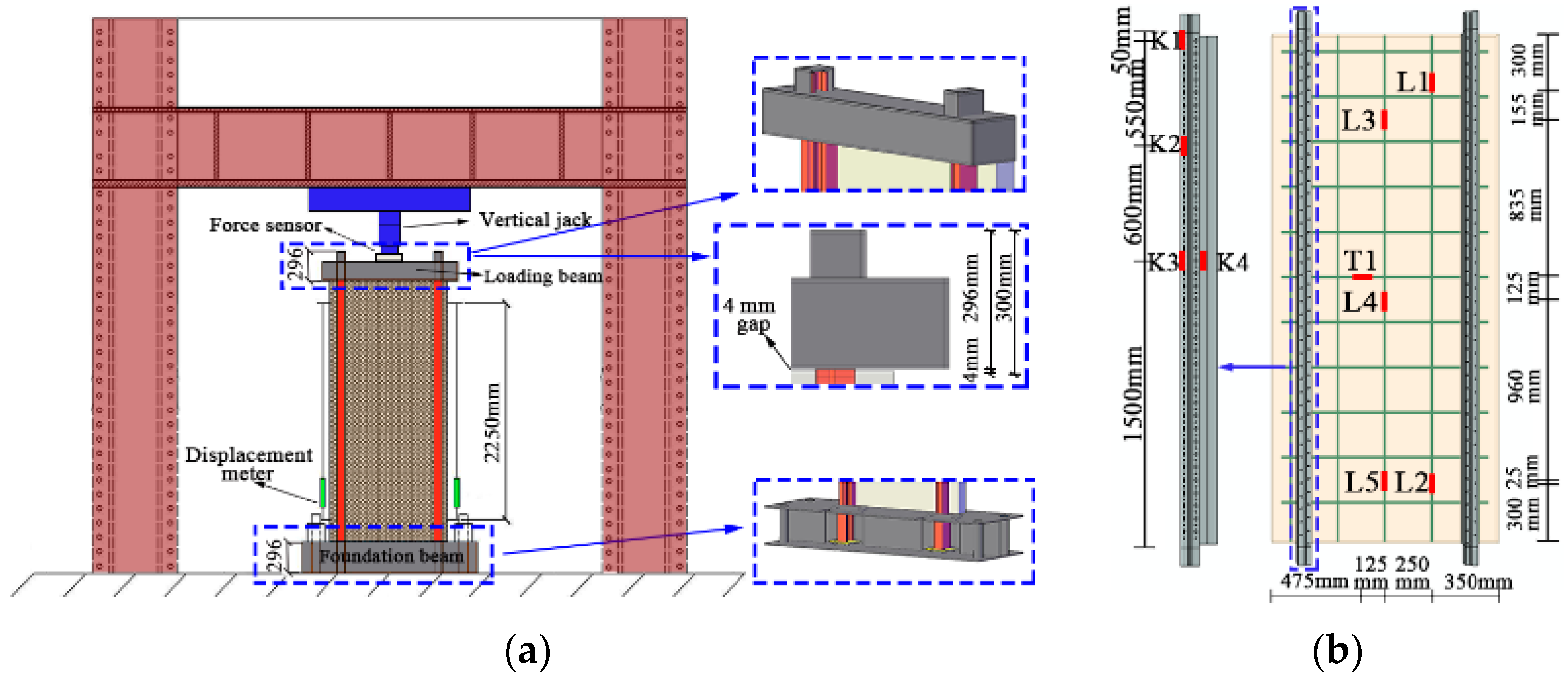
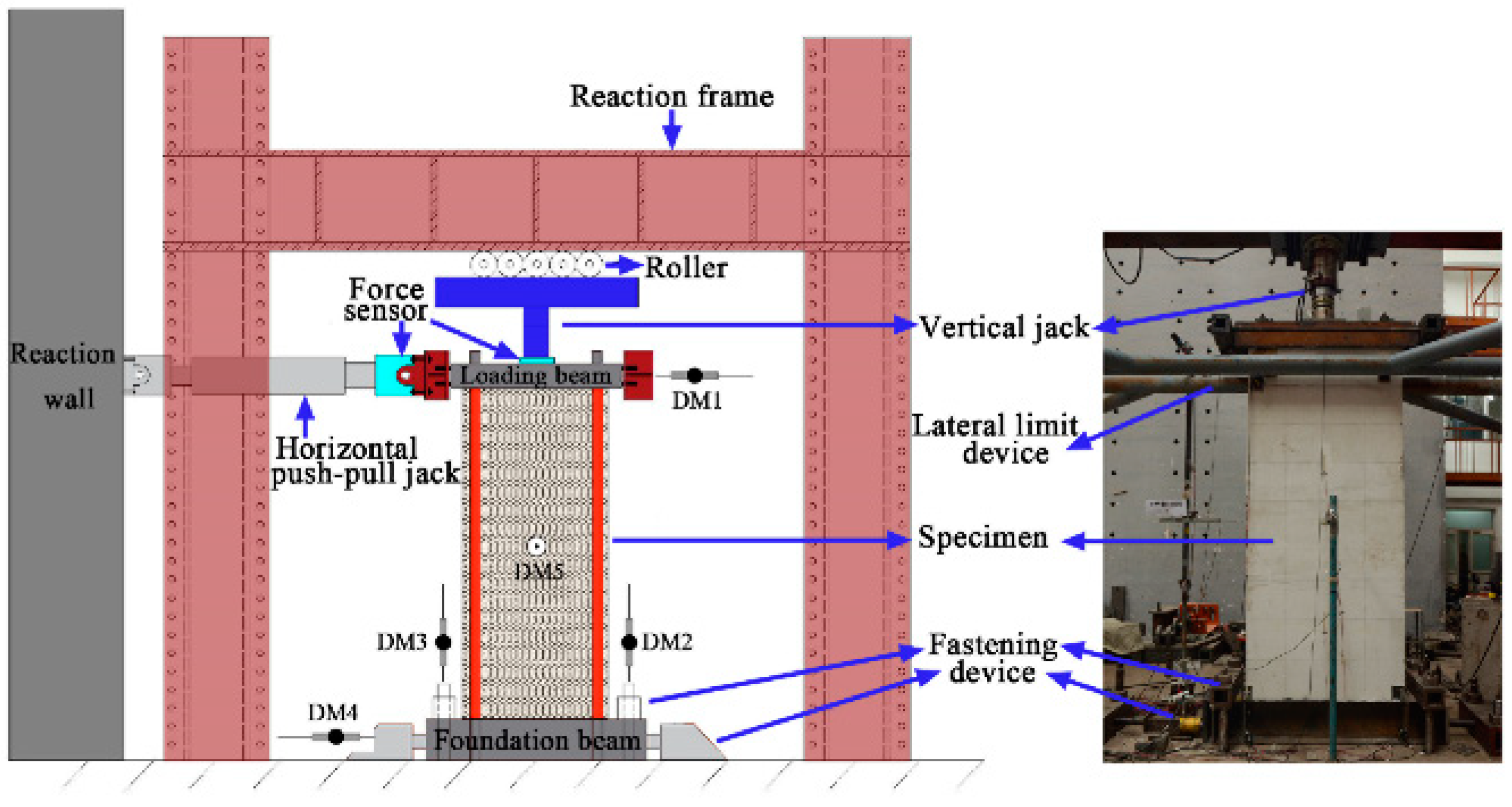
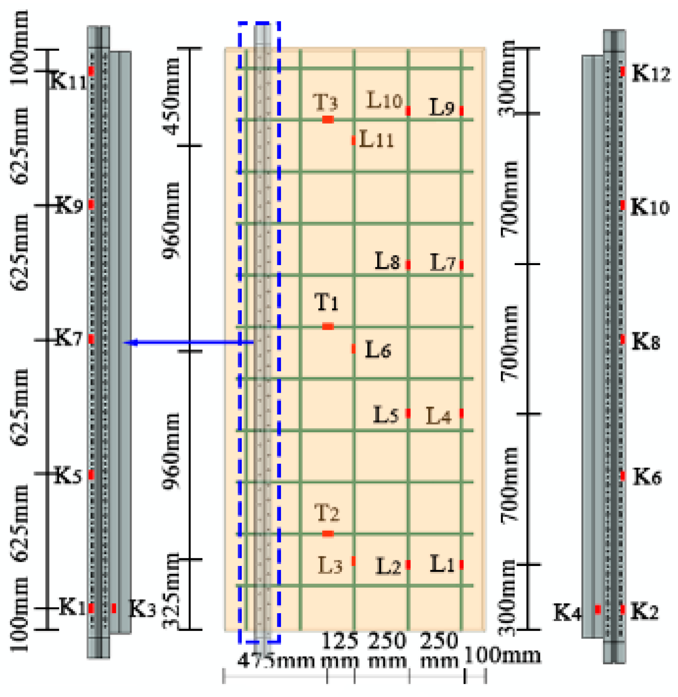
2.3. Loading Device and Test Scheme

In the LS-TMF composite wall structure, the wall assembly and installation are executed using a light steel keel along with upper and lower ring beams. A 4 mm gap is reserved between the TMF plate and the upper and lower ring beams to facilitate the assembly of the composite wall. The vertical load is primarily transferred through the light steel keel. To accurately simulate the actual stress conditions of the composite wall, the vertical load was applied directly to the light steel keel via a loading beam. The loading beam was a box made of welded steel plates. A hole was cut at the keel position, and a small box slightly larger than the cross-sectional size of the keel was welded in place. This design ensures that the loading beam avoids contact with the TMF plate, so the test load is applied directly to the light steel keel, accurately simulating the actual stress conditions.
Compression performance test: The vertical jack was installed on the reaction frame. Before the test loading, the geometric center of the light steel keel section was located on the loading beam, marked, and used as the jack loading point. During the test loading, the load was applied incrementally. The experimental loading rate was set at 0.2 kN/s. At each stage, the load did not exceed 5% of the estimated value. Once 80% of the estimated load was reached, the load for each subsequent stage was limited to no more than 2% of the estimated load. After applying the load at each stage, it was held for 2 min to allow for data collection and observation of any phenomena. The test will be stopped when the composite wall specimen exhibits significant damage and is deemed unsuitable for further loading. At this point, the corresponding load will be recorded as the failure load.
Two light steel keels were equipped with longitudinal displacement meters to record the vertical displacement within the 2250 mm standard distance of the composite wall keel. The displacement meter arrangement is shown in Figure 6a. Strain gauges were primarily arranged on the keel and longitudinal steel bars. Four vertical strain gauges were placed on the keel, labeled K1, K2, K3, and K4. Five strain gauges were installed on the longitudinal steel bar, labeled L1, L2, L3, L4, and L5. Additionally, one strain gauge, T1, was positioned on the transverse steel bar in the middle of the composite wall. The strain arrangement is depicted in Figure 6b.
Seismic performance test: Building on the compression test device, a horizontal push-pull jack was added to apply a horizontal reciprocating load. A fastening device was set on both sides of the foundation beam to prevent horizontal sliding and overturning of the specimen. According to the compression test of the composite wall, a 120 kN vertical load was applied to the LS-TMF composite wall using a vertical jack, and this load was kept constant. Repeated horizontal loads were then applied to the loaded beam through the horizontal pulling and pressing jacks. The height of the loading point from the foundation is 2810 mm. A horizontal lateral limit device was set up to prevent out-of-plane instability of the specimen. The loading device and test site are shown in Figure 7.
The load-deformation loading system was adopted, as shown in Figure 8. Before loading and yielding, the specimens were loaded using load control and graded loading. After the specimen yielded, deformation control was adopted, where the deformation value corresponded to the maximum yield displacement value of the specimen. The step difference for control loading was determined by multiplying the yield displacement value. Given the low strength of the TMF plate material, each stage of load was applied once to observe the damage form of the composite wall during large deformation and to prevent premature fatigue failure of the composite wall.
A total of five displacement meters (DM1-DM5) were arranged to monitor the displacement changes of the specimen during testing. Displacement meter DM1 was positioned at the center of the loading beam to record the specimen’s displacement under horizontal loading. Displacement meters DM2 and DM3 were placed vertically on the foundation beam to capture vertical displacement changes. The displacement meter DM4 was set horizontally on the foundation beam to record any sliding during the loading process. Displacement meter DM5 was placed in the center of the TMF plate to measure the specimen’s out-of-plane deformation. The displacement meter arrangement is depicted in Figure 7. Strain gauges were primarily arranged on the light steel keel and longitudinal steel bars. In total, 12 strain gauges were installed on the keel, as shown in Figure 9. Eleven strain gauges (L1–L11) were placed on the longitudinal steel bars of the composite wall, and three strain gauges (T1–T3) were arranged on the transverse steel bars. For analysis, the column foot strains K1, K2, and K3 on the light steel keel were selected, as well as the longitudinal reinforcement strains L1, L2, and L3. The transverse reinforcement strains T1 and T2 were also chosen for analysis.

3. Damage Process and Failure Characteristics of Specimens

3.1. Compression Performance Test

The destruction processes of specimens CCW5-2 and CCW10-2 were similar. During the initial loading phase, the keel deformed under stress and interacted with the TMF plate, causing the TMF plate to sustain damage, which produced subtle cracking sounds. As the load increased, the TMF plate emitted more pronounced tearing sounds, though no visible damage was observed at this stage. Near the peak load, the bottom of the TMF plate made contact with the foundation, leading to localized crushing. Upon reaching the ultimate load, the end of the keel column buckled and failed. The failure characteristics are depicted in Figure 10a,b.
The failure process of CCW5-2.5 was similar to that of CCW5-2. Due to the increased plate strength and keel thickness, the load value corresponding to the failure characteristics was higher than that of CCW5-2. When the CCW5-2.5 specimen approached the peak load, vertical cracks appeared on the TMF plate at the keel embedment, as shown in Figure 10c.
As the load increased, the upper part of the CCW5-2.5-F specimen developed cracks, which continued to propagate with the increasing load. Vertical cracks appeared on the side of the TMF plate and extended upward. Upon reaching the peak load, both the TMF plate and the fly ash block were crushed under pressure. However, due to the restraining effect of the fly ash block, the keel of the specimen did not exhibit buckling. The failure characteristics of CCW5-2.5-F are shown in Figure 10d.

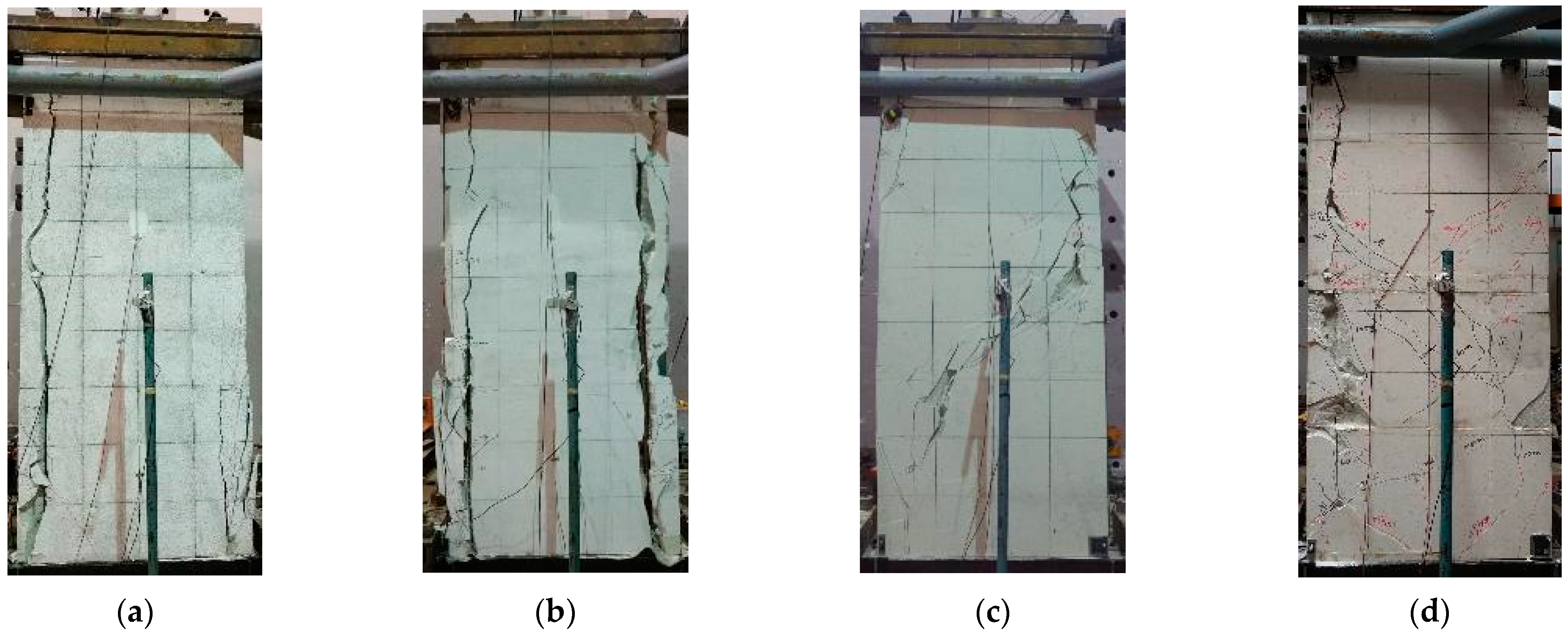
3.2. Seismic Performance Test

The ECW5 specimen showed no noticeable damage at the beginning of the loading process. When a horizontal load of 25 kN was applied, a faint sound was heard from the TMF plate. As the load increased, the noise from the TMF plate became more pronounced. At 35 kN, a crack appeared at the base of the TMF plate where the keel was embedded. As the horizontal load continued to increase, this crack gradually propagated at the keel embedding location. Upon reaching the peak load, a vertical through-wall crack developed, leading to the detachment of the keel from the TMF plate, as depicted in Figure 11a.
The ECW10 specimen displayed no evident signs of damage during the initial loading phase. When subjected to a horizontal load of 30 kN, a faint sound was emitted by the TMF plate, which grew louder upon the application of a 40 kN horizontal load, resulting in cracking at its base where it was embedded in the keel. As the horizontal load increased, the destructive sound of the TMF plate intensified, and cracks gradually developed at the keel embedding location. When the horizontal load reached its peak, cracks appeared on both sides of the TMF plate at the keel embedding location, resulting in through cracks. This caused the light steel keel and TMF plate to peel off, reducing the specimen’s bearing capacity, as shown in Figure 11b. The failure process was similar to that observed for ECW5 but occurred at higher loads due to the enhanced strength of the ECW10 specimen.
The ECW5-F specimen did not exhibit any apparent damage initially under loading conditions. However, when subjected to a horizontal load of 25 kN, there was an audible indication from within its structure. When the horizontal load reached 50 kN, cracks appeared at the keel embedding location. At 80 kN, shear diagonal cracks gradually developed in the TMF plate due to the restraining effect of the fly ash blocks. As the load increased, these diagonal cracks expanded. Upon reaching the peak load, the specimen experienced shear crack failure, resulting in a decrease in bearing capacity, as shown in Figure 11c.
There was no significant damage observed during the initial loading of specimen ECW5-F-P. When the horizontal load reached 15 kN, the TMF plate emitted a slight noise. At 25 kN, cracks appeared at the keel embedding location. As the load increased, these cracks developed downward. Similar to ECW5-F, when the horizontal load reached 45 kN, the cracks evolved from vertical to oblique. As the horizontal load continued to increase, vertical cracks extended further downward, and shear diagonal cracks gradually intensified. Upon reaching the peak load, due to the lower integrity of the spliced plate specimen compared to the whole plate specimen, the TMF plate eventually developed vertical cracks at the keel embedding location, leading to a decrease in the specimen’s bearing capacity, as shown in Figure 11d.

4. Test Results and Analysis

4.1. Analysis of Compression Test Results

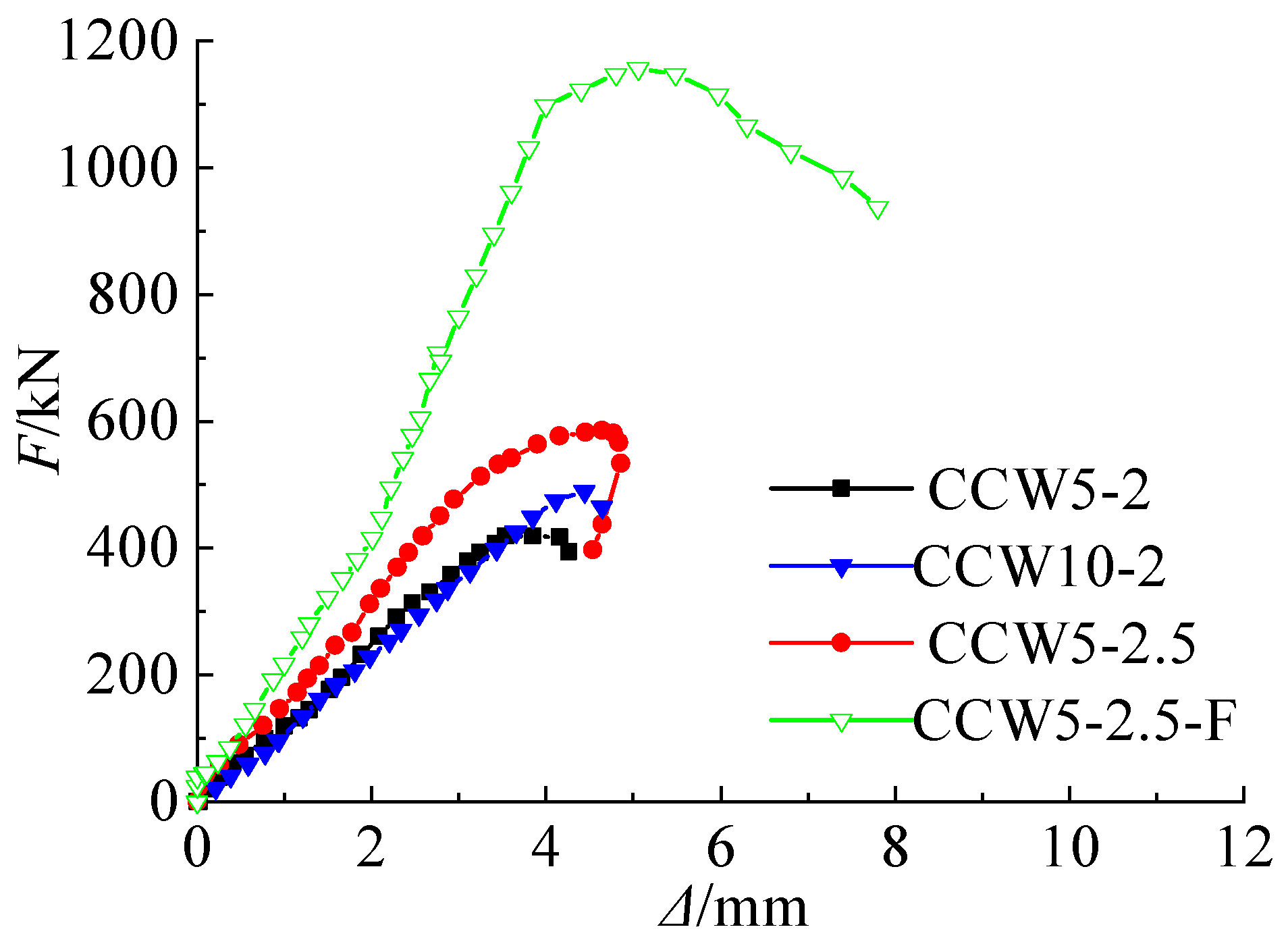
4.1.1. Load-Displacement Curve of Compression Test

The load (F)-displacement (Δ) curve of the LS-TMF composite wall specimen is shown in Figure 12. In the figure, F represents the vertical load, and Δ represents the vertical displacement.
As shown in Figure 12, the load-displacement curve of the composite wall exhibited a secondary stiffness-strengthening process. This occurred because the TMF plate gradually contributed to the load-bearing process after the keel was compressed and deformed. The thickness of the keel significantly influenced the peak bearing capacity of the composite wall. In specimens without fly ash block filling, buckling at the keel column’s ends led to failure. However, increasing the keel thickness enhanced the stability of the composite wall. The TMF plate helped to restrict keel instability, and increasing its strength improved the composite wall’s compressive capacity. As the TMF plate gradually engaged in the loading process, its increased strength enhanced the secondary stiffness of the composite wall. When the composite wall was filled with fly ash blocks, the compressive performance was significantly improved due to the restraining effect of the fly ash blocks.

4.1.2. Bearing Capacity of Compression Test

Table 4 presents the key characteristic values observed during the tests. The peak load (Np) of each specimen is compared based on the bearing capacity of the CCW5-2 specimen. In the table, Np represents the peak load, Δp denotes the displacement corresponding to the peak load, and Δu indicates the displacement at the point of specimen failure.
Based on the analysis of Table 4, the ultimate bearing capacity of the CCW5-2.5 specimen increased by 39.70% compared to the CCW5-2 specimen, indicating that the increase in keel thickness significantly enhanced the peak ultimate bearing capacity of the composite wall. The ultimate bearing capacity of the CCW10-2 specimen was 16.76% higher than that of the CCW5-2 specimen, demonstrating that improving the strength of the TMF plate can enhance its restraining effect on the light steel keel, thereby improving the composite wall’s compressive performance. Furthermore, the ultimate bearing capacity of the CCW5-2.5-F specimen was 90.37% higher than that of the CCW5-2.5 specimen. This suggests that filling the composite wall with fly ash blocks can significantly improve its compressive performance, with the failure decline curve of the filled specimens being gentler than that of the other specimens.

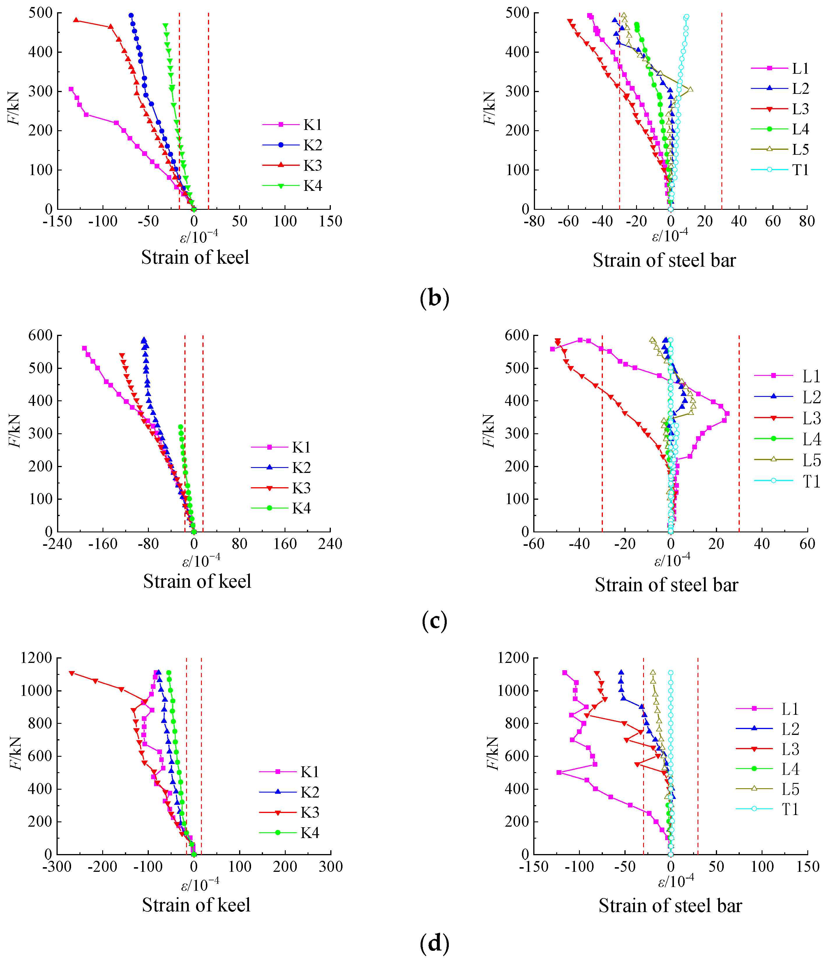
4.1.3. Strain Analysis of Compression Test

The stress state of the steel bars and light steel keels in the composite wall was analyzed by examining the strain points K1–K4 for the keel, L1–L5 for the longitudinal steel bars, and T1 for the transverse steel bars. The load-strain curve of the specimen is shown in Figure 13a–d. The red dotted lines in the figures indicate the yield strain values for the steel bars and the light steel keel, respectively.
As shown in Figure 13, the strain value of the transverse reinforcement was relatively small, indicating minimal stress on the composite wall after compression. The light steel keel experienced significant stress and reached its yield strain under pressure. For the CCW5-2 and CCW5-2.5 specimens, the strain data for the K4 were lost during the later loading stages, although the K4 strain had already reached the yield strain during the mid-loading period.
After the TMF plate began to bear load, the vertical steel bars were subjected to pressure. The strain values of the longitudinal reinforcement varied among the specimens. Only one measuring point of the longitudinal reinforcement for CCW5-2 reached the yield strain, while three measuring points for CCW5-2.5-F reached the yield strain. The presence of fly ash blocks restricted the keel, allowing the TMF plate and longitudinal steel bars to contribute more effectively to the load-bearing process. This enhancement improved the compressive performance of the composite wall during the later stages of loading.

4.1.4. Formula for Compressive Bearing Capacity

The light steel keel serves as the primary load-bearing element in the LS-TMF composite wall. During compression, the TMF plate provides support to the steel keel, enhancing its stability within the wall structure. To determine the compressive bearing capacity of this composite wall, we utilized strength and stability calculation formulas based on the guidelines for axial compression members from the Technical Code of Cold-formed Thin-walled Steel Structures (GB 50018-2002) [25]. The calculated values were then compared with the results obtained from experimental testing, as presented in Table 5.
N A en f
where N is the axial compressive load. Aen is the effective net cross-sectional area of the compression member. f is the compressive strength of the steel.
The stability of axial compression members should be calculated using the following formula.
N φ A e f
where φ is the stability coefficient of the compression member, set to φ = 0.69 according to the code. Ae is the effective cross-sectional area.
As shown in Table 5, the TMF plate provided effective restraint to the light steel keel, which led to a relatively large error in the results obtained from the stability calculation formula. The results obtained using the strength calculation formula (Formula (1)) were closer to the ultimate bearing capacity of the test specimen, with an average error of 5.47%. When designing the compressive bearing capacity of composite walls, it was recommended to calculate the compressive bearing capacity of the light steel keel based on the strength calculation formula from the “Technical Code of Cold-formed Thin-walled Steel Structures”. In engineering practice, it was advisable to use a cross-sectional configuration that included fly ash to increase the restraint on the keel, with the resulting strength gain contributing to the wall’s safety reserve.

4.2. Analysis of Seismic Test Results

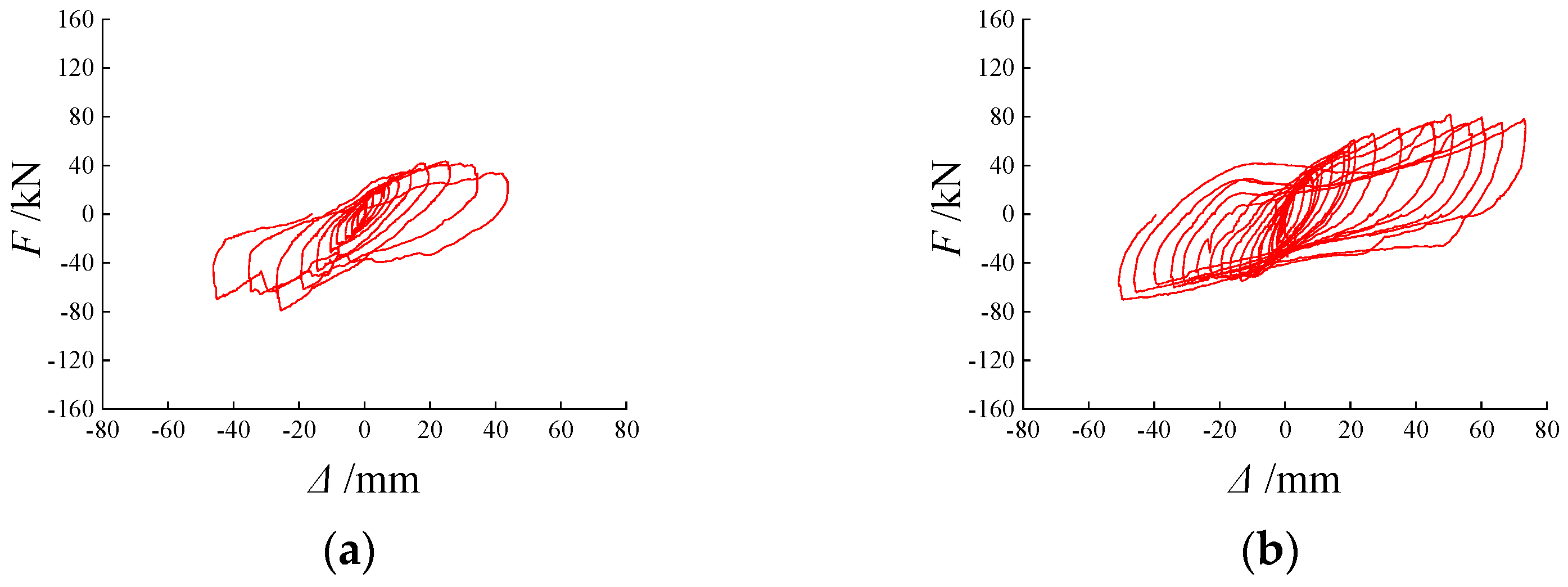
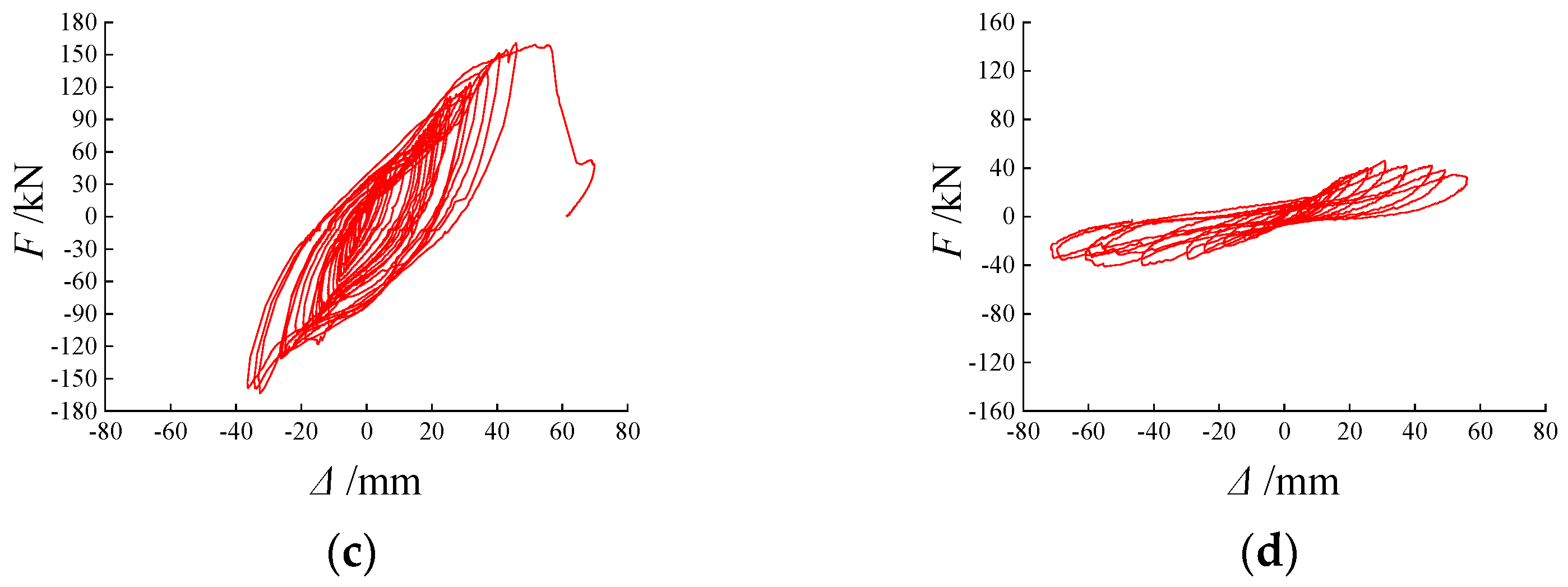
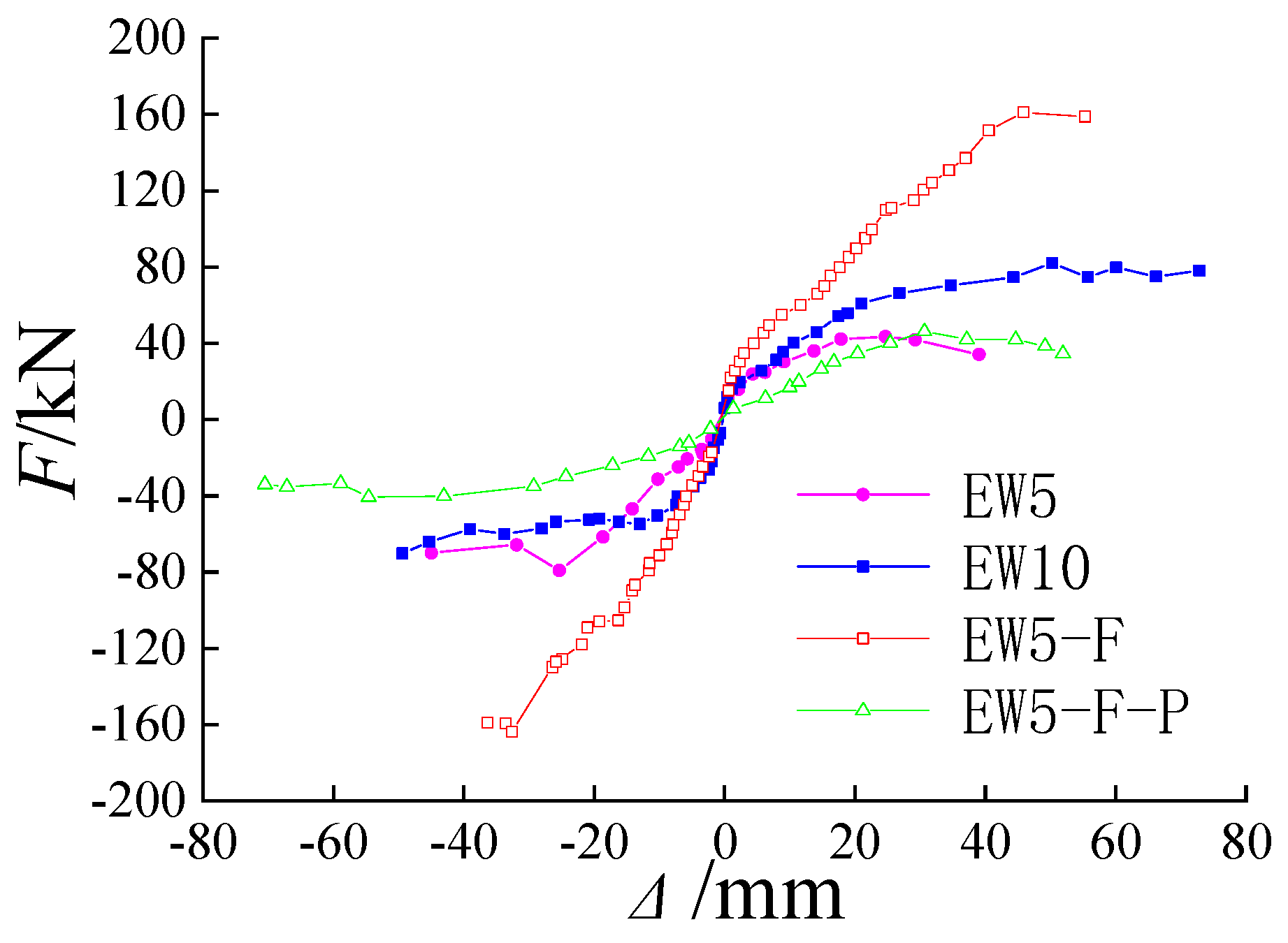
4.2.1. Load-Displacement Curve of Seismic Test

The hysteretic curves “load (F)-horizontal displacement (Δ)” for the 4 LS-TMF composite wall specimens are shown in Figure 14. The skeleton curve of specimens is shown in Figure 15. In the figure, F represents the horizontal load, and Δ denotes the horizontal displacement.
As shown in Figure 14 and Figure 15, when the strength of the TMF plate increased, the restraining effect on the light steel keel was enhanced, which positively impacted the bearing capacity and hysteretic performance of the composite wall. The hysteresis curve of the ECW10 specimen was fuller than that of the ECW5 specimen.
With the addition of the fly ash block, the TMF plate, light steel keel, steel bar, and fly ash block worked effectively together. The fly ash block increased the constraint on the light steel keel, significantly improving the bearing capacity of the composite wall specimens and resulting in a relatively full hysteretic curve. The failure mode of the ECW5-F specimen shifted from vertical cracking failure to shear oblique crack failure.
When the TMF plate utilized a splicing configuration, the overall integrity of the plate was compromised. Under force, each splicing plate gradually failed at the embedding points of the light steel keel. The synergistic performance between the fly ash and the splicing plate weakened, leading to a hysteresis curve for the specimen that was less full compared to other specimens. Vertical cracks appeared on the splicing plate, and the ultimate failure was governed by these vertical cracks. The bearing capacity was significantly lower than that of the whole plate specimen (ECW5-F), indicating that the integrity of the TMF plate plays a substantial role in the seismic performance of the composite wall.

4.2.2. Bearing Capacity of Seismic Test

The characteristic values of the test bearing capacity were analyzed, including the yield load Fy, yield displacement Δy, ultimate load Fu, ultimate displacement Δu, failure load Fd, and failure displacement Δd, as shown in Table 6. The yield load Fy of the specimen was calculated using the energy equivalent method [26]. In Table 6, μ is the ductility coefficient of the specimen, and the calculation formula is shown in Equation (3).
μ = + Δ d + Δ d + Δ y + Δ y
whereΔd is the damage displacement and Δy is the yield displacement.
As shown in Table 6, the strength of the TMF plate enhanced the bearing capacity of the composite wall, resulting in an increase in ultimate load of approximately 24.22%. When fly ash blocks were incorporated into the composite wall, the bearing capacity was significantly improved. The ultimate load of the ECW5-F specimen was approximately 165.14% higher than that of the ECW5 specimen; however, the ductility coefficient of the ECW5-F specimen was lower than that of the ECW5. The reduced integrity of the TMF plate weakened the restraining ability of the light steel keel, which in turn reduced the bearing capacity of the composite wall. Consequently, the ultimate bearing capacity of the ECW5-F-P specimen was 29.02% lower compared to the ECW5 specimen.

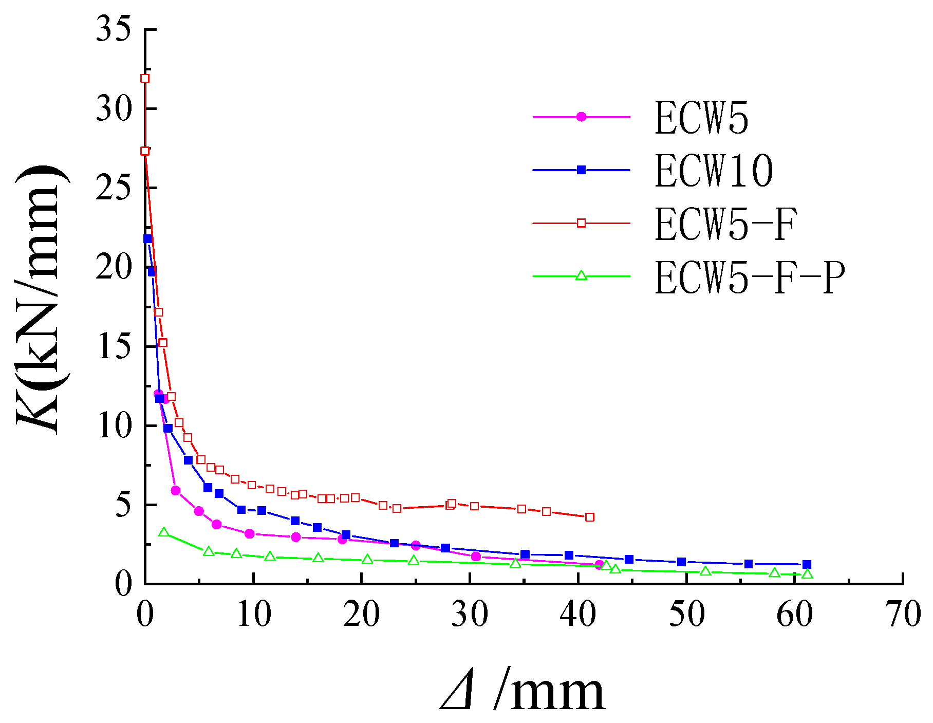
4.2.3. Stiffness Degradation

The average secant stiffness was used to analyze the stiffness degradation of the specimen, as illustrated in Figure 16. The calculation formula for average secant stiffness is provided in Equation (4).
K i = ( F i + / Δ i + + F i / Δ i ) 2
where Ki is the average secant stiffness for each stage; Fi+ and Fi are the positive and negative peak loads for each stage, respectively; Δi+ and Δi are the positive and negative peak displacements for each stage, respectively.
The initial stiffness values for ECW5, ECW10, ECW5-F, and ECW5-F-P were 11.69 kN/mm, 21.80 kN/mm, 31.92 kN/mm, and 3.22 kN/mm, respectively. Increasing the strength of the TMF plate improved the initial stiffness of the specimens and slowed down the rate of stiffness degradation. When fly ash blocks were added between the light steel keels of the composite wall, both the initial stiffness and stiffness degradation were significantly enhanced. The initial stiffness of ECW5-F was 2.73 times that of ECW5, 1.46 times that of ECW10, and 9.91 times that of ECW5-F-P. However, splicing joints in the TMF plate affected its overall integrity, weakened the TMF plate’s ability to restrain the light steel keel, and consequently reduced the initial stiffness of the composite wall.

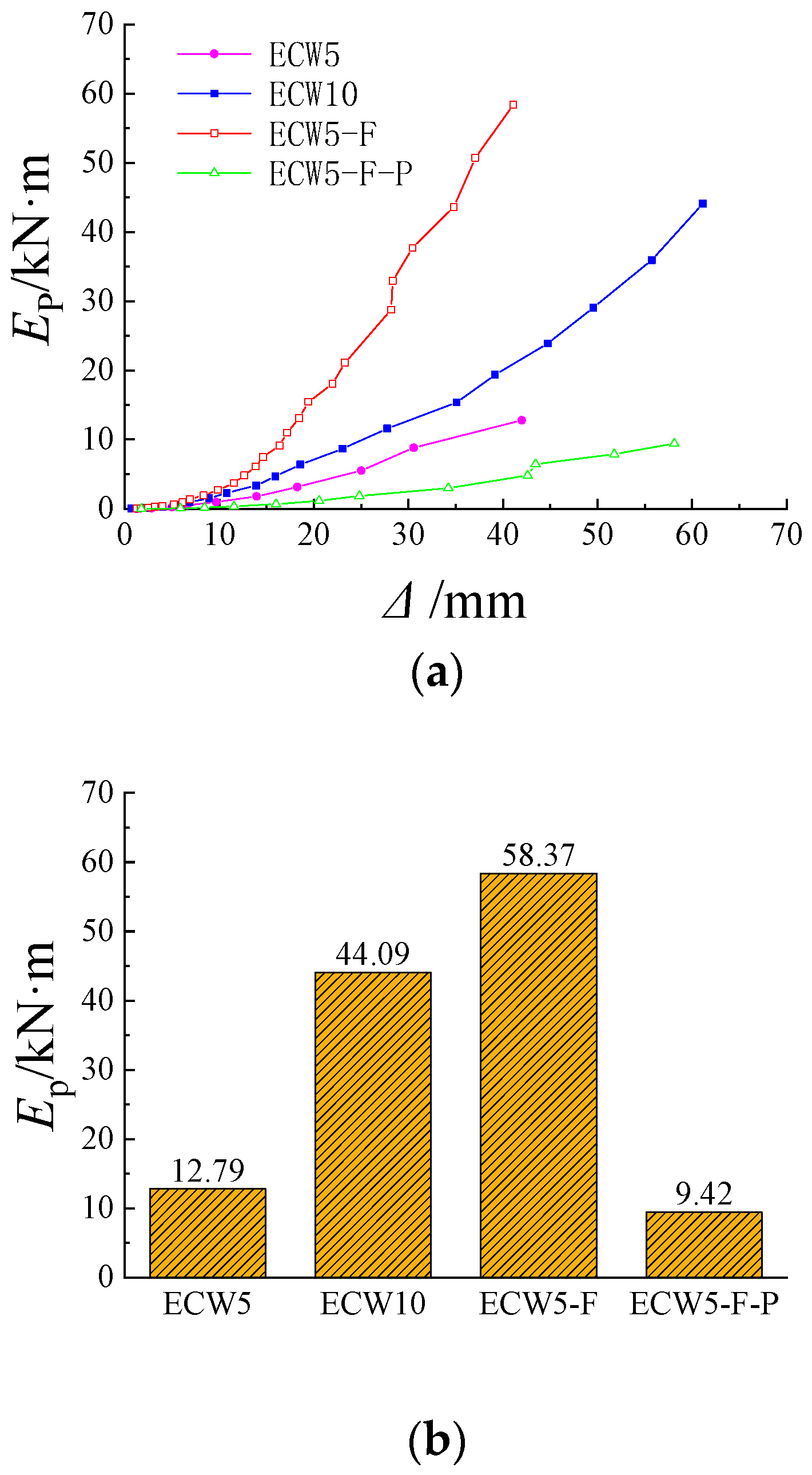
4.2.4. Energy Dissipation

The cumulative energy dissipation (Ep) of the specimen was analyzed by superimposing the envelope area of each cyclic hysteresis loop, which reflects the energy dissipation capacity of the specimen, as shown in Figure 17.
The final cumulative energy dissipation of ECW5, ECW10, ECW5-F, and ECW5-F-P was 12.79 kN/m, 44.09 kN/m, 58.37 kN/m, and 9.42 kN/m, respectively. The increase in the strength of the TMF plate enhanced its restraining effect on the light steel keel, thereby improving the seismic energy dissipation capacity of the composite wall. The cumulative energy dissipation of the ECW10 specimen was approximately 3.44 times that of the ECW5 specimen. When fly ash blocks were added to the composite wall, the TMF plate, light steel keel, and fly ash blocks collaborated effectively, significantly enhancing the energy dissipation capacity of the composite wall. The energy dissipation capacity of the ECW5-F specimen was about 4.56 times that of the ECW5 specimen. Although fly ash blocks were also added to the ECW5-F-P specimen, the TMF plate consisted of spliced plates, resulting in poor overall performance and a reduced restraining effect on the light steel keel. Consequently, the energy dissipation capacity was lower than that of the whole plate specimen, approximately 0.74 times that of the ECW5.

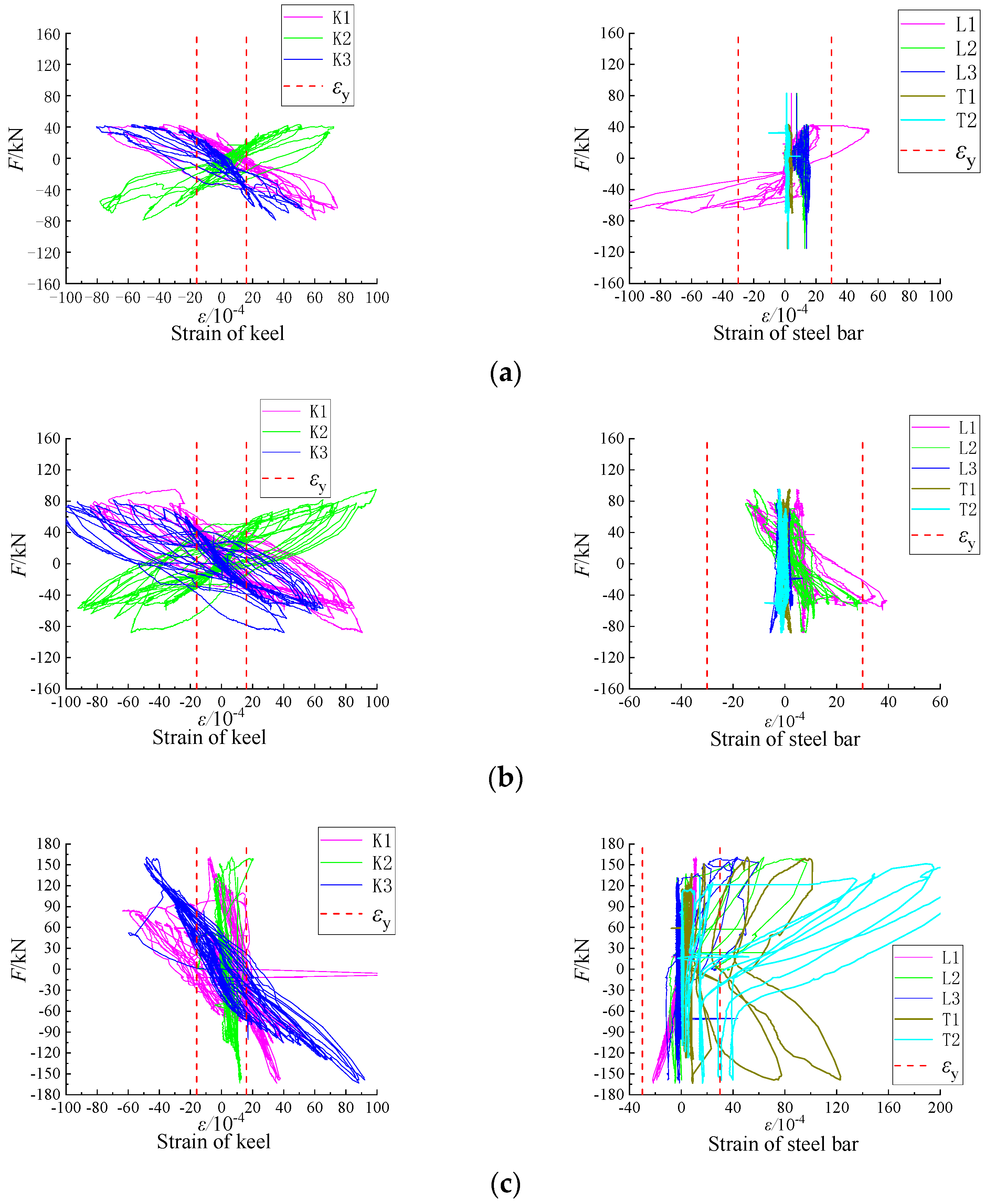
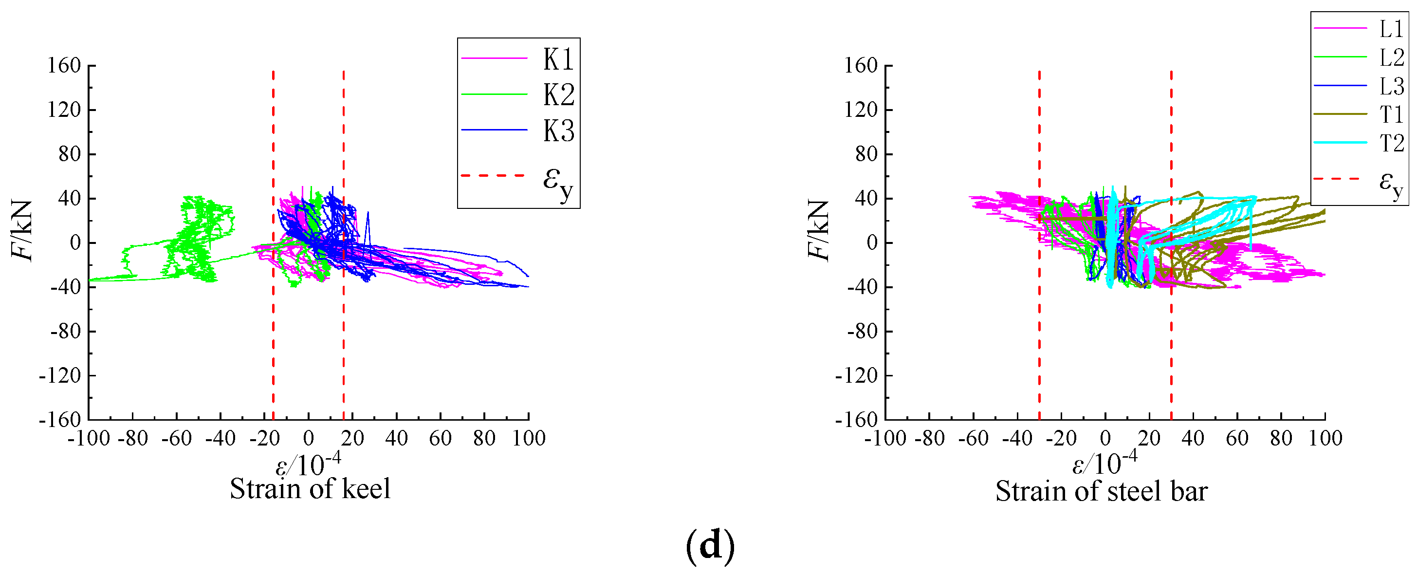
4.2.5. Strain Analysis of Seismic Test

The load-strain curve was used to analyze the stress state of the light steel keel and steel bars in the composite wall. The analysis focused on the strain values K1, K2, and K3 at the column foot of the light steel keel. For longitudinal reinforcement, the strains L1, L2, and L3 were analyzed, while for transverse reinforcement, T1 and T2 were considered. The strain analysis of the light steel keel and steel bar of the specimen is illustrated in Figure 18. In these figures, the vertical axis represents the horizontal load, the horizontal axis indicates the strain value of the specimen, and the red dotted line marks the yield strain value for both the steel bar and the light steel keel, respectively.
As seen in Figure 18, the column foot strains K1, K2, and K3 of the light steel keel in ECW5, ECW10, ECW5-F, and ECW5-F-P all reached the yield strain. The ECW5-F-P specimen exhibited a sudden change in light steel keel strain compared to the other specimens due to the poor integrity of the TMF plate, which caused the plate to break down and disengage sequentially. This breakdown led to a redistribution of stress within the composite wall specimen.
After the TMF plate was damaged at the keel insertion of the ECW5 and ECW10 specimens, the lateral longitudinal steel bar L1 of the TMF plate experienced a sudden change in strain and quickly reached the yield strain due to stress redistribution. In the ECW5 specimen, there were no shear-inclined cracks between the light steel keels, resulting in minimal force on the longitudinal steel bars in the middle, so L2 and L3 did not reach the yield strain. The ECW10 specimen, with an improved strength of the TMF plate, exhibited a higher degree of participation in force compared to the ECW5 specimen. L2 approached the yield strain during the late loading stage, while L3 did not reach the yield strain. The failure of both the ECW5 and ECW10 specimens was characterized by vertical fracture failure, leading to minimal involvement of the transverse reinforcement, and as a result, T1 and T2 did not reach the yield strain.
Fly ash blocks were filled between the light steel keels of the ECW5-F specimen, which enhanced the constraints on the light steel keels. The primary failure mode was shear-inclined crack failure, with the reinforcement between the light steel keels fully engaged in bearing the load. Consequently, L2, L3, T1, and T2 all reached the yield state during the late loading stage. Since shear failure is a brittle failure, the TMF plate quickly disengaged, causing sudden changes in the strains of transverse steel bars T1 and T2 during the late loading period. For the ECW5-F-P specimen, the failure was mainly due to vertical cracks, with the outer longitudinal steel bar L1 reaching the yield state in the late loading stage. As the specimens were filled with fly ash blocks, shear inclined cracks appeared during the loading process, leading to the engagement of the steel bars between the light steel keels in bearing the load, with L2, T1, and T2 all reaching the yield strain.

5. Conclusions

The LS-TMF composite wall is a high-performance exterior wall system that integrates assembly, sustainability, insulation, and decorative functions. This structural system offers clear load-bearing characteristics and convenient construction, making it a promising option for the market. The in-plane performance tests conducted on the composite wall with varying parameters included compression performance tests and low-cycle repeated load tests. The primary conclusions drawn from these tests are as follows:
(1)
The light steel keel, steel bar, and TMF plate in the composite wall demonstrated good working performance. The light steel keel served as the primary load-bearing component. The interaction between the TMF plate and the light steel keel enhanced the stability of the keel. Increasing the thickness of the light steel keel significantly improved the composite wall’s ultimate bearing capacity and stability. Strengthening the TMF plate enhanced the restraint on the light steel keel and improved the composite wall’s compressive performance. When the composite wall was filled with fly ash blocks, its compression performance was significantly improved, with the ultimate bearing capacity of CCW5-2.5-F increasing by 90.37% compared to CCW5-2.5. When designing the compressive bearing capacity of composite walls, it was recommended to calculate the compressive bearing capacity of the light steel keel based on the strength calculation formula.
(2)
Under horizontal seismic action, failure typically occurred at the location where the light steel keel was embedded in the TMF plate. Improving the TMF plate’s strength enhanced its restraint on the light steel keel, leading to increased horizontal bearing capacity, stiffness, and energy dissipation capacity of the composite wall. Specifically, the horizontal ultimate load, initial stiffness, and cumulative energy dissipation of the ECW10 specimen were 1.24 times, 1.86 times, and 3.45 times those of the ECW5 specimen, respectively.
(3)
After filling fly ash blocks between the keels, the restraint effect on the keels was enhanced, resulting in a change in damage pattern from vertical through crack failure to shear oblique crack failure. The combination of fly ash blocks, light steel keels, and TMF plates significantly improved the horizontal bearing capacity, stiffness, and energy dissipation of the composite wall. Specifically, the horizontal ultimate load, initial stiffness, and cumulative energy consumption of the ECW5-F specimen were 2.65 times, 2.73 times, and 4.56 times those of the ECW5 specimen, respectively. This structural configuration—incorporating light steel keels, TMF plates, and fly ash blocks—improved thermal insulation and enhanced in-plane stress performance.
(4)
When a splicing structure was used for the TMF plate, its overall integrity was compromised. This led to a weakened restraint capability of the light steel keel and a reduction in the composite wall’s horizontal bearing capacity, stiffness, and energy dissipation capacity. The ultimate load, initial stiffness, and cumulative energy dissipation of the ECW5-F-P specimen were 0.71 times, 0.26 times, and 0.74 times those of the ECW5 specimen, respectively. The splicing plate structure adversely affected the seismic performance of the composite wall, making it unsuitable for seismic design applications.
This study focuses on the in-plane performance of LS-TMF composite walls, detailing the processes involved in compressive and seismic performance tests, and analyzing the failure characteristics and load-bearing capacity of the composite walls. Further theoretical analysis is needed for these composite walls. In the future, the research team will develop a refined finite element model to investigate the influence of various parameters on compressive and seismic performance, optimize the construction of composite walls, and enhance the design theory related to them.

Author Contributions

Conceptualization, J.B. and W.C.; methodology, J.C.; investigation, L.Z.; data curation, Y.Y.; writing—original draft preparation, Y.Y.; writing—review and editing, J.B.; visualization, L.Z.; supervision, W.C. and J.C.; funding acquisition, J.B. All authors have read and agreed to the published version of the manuscript.

Funding

This research was funded by the Tianjin Natural Science Foundation (22JCQNJC00680) and the Tianjin Enterprise Technology Commissioner Project (23YDTPJC00790) of the Tianjin Science and Technology Bureau.

Data Availability Statement

The original contributions presented in the study are included in the article, further inquiries can be directed to the corresponding authors.

Conflicts of Interest

Author Lidong Zhao was employed by the company China Construction Eighth Engineering Division Co., Ltd. The remaining authors declare that the research was conducted in the absence of any commercial or financial relationships that could be construed as a potential conflict of interest.

References

  1. International Energy Agency (IEA). Buildings. Available online: https://www.iea.org/reports/buildings (accessed on 24 September 2024).
  2. Mallum, I.; Mohd.Sam, A.R.; Lim, N.H.A.S.; Omolayo, N. Sustainable Utilization of Waste Glass in Concrete: A Review. Silicon 2021, 14, 3199–3214. [Google Scholar] [CrossRef]
  3. Shi, J.; Li, Q.; Li, H.; Li, S.; Zhang, J.; Shi, Y. Eco-design for recycled products: Rejuvenating mullite from coal fly ash. Resour. Conserv. Recycl. 2017, 124, 67–73. [Google Scholar] [CrossRef]
  4. Dong, H.; Qin, J.; Cao, W.; Yang, L.; Yin, F.; Wang, R. Shaking table tests on concrete-filled steel tubular-framed building assembled with microcrystalline foam boards. Structures 2021, 34, 2098–2114. [Google Scholar] [CrossRef]
  5. Llantoy, N.; Chàfer, M.; Cabeza, L.F. A comparative life cycle assessment (LCA) of different insulation materials for buildings in the continental Mediterranean climate. Energy Build. 2020, 225, 110323. [Google Scholar] [CrossRef]
  6. Ameri, F.; Zareei, S.A.; Behforouz, B. Zero-cement vs. cementitious mortars: An experimental comparative study on engineering and environmental properties. J. Build. Eng. 2020, 32, 101620. [Google Scholar] [CrossRef]
  7. Deng, F.; Wang, F.; Shi, X.; Liu, L.; Liao, Q. Synthesis and properties of foam glass-ceramics from granite tailings by using SiC and MnO2 as the mixed foaming agent. Ceram. Int. 2023, 49, 34647–34656. [Google Scholar] [CrossRef]
  8. Fernandes, H.R.; Tulyaganov, D.U.; Ferreira, J.M.F. Production and characterisation of glass ceramic foams from recycled raw materials. Adv. Appl. Ceram. 2009, 108, 9–13. [Google Scholar] [CrossRef]
  9. Fernandes, H.R.; Tulyaganov, D.U.; Ferreira, J.M.F. Preparation and characterization of foams from sheet glass and fly ash using carbonates as foaming agents. Ceram. Int. 2009, 35, 229–235. [Google Scholar] [CrossRef]
  10. Francis, A.A.; Abdel Rahman, M.K. Experimental design for optimisation of density and water absorption capacity of glass–ceramic foams prepared from silica rich wastes. Powder Metall. 2013, 56, 295–303. [Google Scholar] [CrossRef]
  11. Ding, L.; Ning, W.; Wang, Q.; Shi, D.; Luo, L. Preparation and characterization of glass-ceramic foams from blast furnace slag and waste glass. Mater. Lett. 2015, 141, 327–329. [Google Scholar] [CrossRef]
  12. Ivanov, K.S. Extrusion Method for Producing Microgranular Foam-Glass Ceramic from Zeolite Rocks. Refract. Ind. Ceram. 2021, 62, 157–161. [Google Scholar] [CrossRef]
  13. Yio, M.H.; Xiao, Y.; Ji, R.; Russell, M.; Cheeseman, C. Production of foamed glass-ceramics using furnace bottom ash and glass. Ceram. Int. 2021, 47, 8697–8706. [Google Scholar] [CrossRef]
  14. Karamanov, A.; Hamzawy, E.M.; Karamanova, E.; Jordanov, N.B.; Darwish, H. Sintered glass-ceramics and foams by metallurgical slag with addition of CaF2. Ceram. Int. 2020, 46, 6507–6516. [Google Scholar] [CrossRef]
  15. Gao, H.T.; Liu, X.H.; Chen, J.Q.; Qi, J.L.; Wang, Y.B.; Ai, Z.R. Preparation of glass-ceramics with low density and high strength using blast furnace slag, glass fiber and water glass. Ceram. Int. 2018, 44, 6044–6053. [Google Scholar] [CrossRef]
  16. Vereshagin, V.I.; Sokolova, S.N. Granulated foam glass–ceramic material from zeolitic rocks. Constr. Build. Mater. 2008, 22, 999–1003. [Google Scholar] [CrossRef]
  17. Liu, Y.; Yang, H.; Luan, L.; Xu, X.; Liu, Y.; Du, X. Three failure modes of High-Strength Steel (HSS) perfobond connector embedded in UHPC. Eng. Struct. 2023, 286, 116147. [Google Scholar] [CrossRef]
  18. Hao, Y.; Qin, L.; He, X.; Su, T.; Sun, H.; Wang, H. Experimental study on seismic behavior of fabricated lightweight steel solid waste High-strength foam concrete composite wall. Structures 2023, 52, 921–932. [Google Scholar] [CrossRef]
  19. Nicoletti, V.; Arezzo, D.; Carbonari, S.; Gara, F. Detection of infill wall damage due to earthquakes from vibration data. Earthq. Eng. Struct. Dyn. 2022, 52, 460–481. [Google Scholar] [CrossRef]
  20. Furtado, A.; Rodrigues, H.; Rodrigues, M.F.; Arêde, A.; Varum, H. A novel holistic approach for the seismic-energy performance assessment of masonry infill walls. Soil Dyn. Earthq. Eng. 2023, 173, 108129. [Google Scholar] [CrossRef]
  21. GB/T 5486-2008; Test Method for Inorganic Hard Insulation Products. Standards Press of China: Beijing, China, 2008.
  22. Bian, J.; Cao, W.; Yang, L.; Xiong, C. Experimental Research on the Mechanical Properties of Tailing Microcrystalline Foam Glass. Materials 2018, 11, 2048. [Google Scholar] [CrossRef]
  23. GB/T228-2002; Metallic Materials-Tensile Testing at Ambient Temperature. China Architecture & Building Press: Beijing, China, 2002.
  24. GB/T 11969-2008; Test Method of Autoclaved Aerated Concrete. Standards Press of China: Beijing, China, 2008.
  25. GB 50018-2002; Technical Code of Cold-Formed Thin-Walled Steel Structures. China Planning Press: Beijing, China, 2002.
  26. Bian, J.; Cao, W.; Qiao, Q.; Zhang, J. Experimental and numerical studies of prefabricated structures using CFST frame and composite wall. J. Build. Eng. 2022, 48, 103886. [Google Scholar] [CrossRef]
Figure 1. TMF plate material: (a) Multi-layer density material; (b) decorative surface insulation material.
Buildings 14 03196 g001
Figure 2. The LS-TMF composite wall structure: (a) Composite wall; (b) Sample houses.
Buildings 14 03196 g002
Figure 3. Manufacturing process of specimen: (a) Grooving of the TMF plate; (b) Placement of longitudinal steel bars; (c) Placement of the keel and transverse steel bars.
Buildings 14 03196 g003
Figure 4. Dimension and Section of the Specimen: (a) The dimensions of ECW5-F-P; (b) The section diagram of ECW5-F.
Buildings 14 03196 g004
Figure 5. Compression test: (a) Cube compression test; (b) Prism compression test.
Buildings 14 03196 g005
Figure 6. Test device and position of strain gauge: (a) Test device; (b) Position of strain gauge.
Buildings 14 03196 g006
Figure 7. Test device and photo.
Buildings 14 03196 g007
Figure 8. Loading protocol.
Buildings 14 03196 g008
Figure 9. Arrangement of strain gauges.
Buildings 14 03196 g009
Figure 10. Failure characteristics of specimens: (a) CCW5-2; (b) CCW10-2; (c) CCW5-2.5; (d) CCW5-2.5-F.
Buildings 14 03196 g010
Figure 11. The failure characteristics of seismic test specimens: (a) ECW5; (b) ECW10; (c) ECW5-F; (d) ECW5-F-P.
Buildings 14 03196 g011
Figure 12. Load-displacement curve.
Buildings 14 03196 g012
Figure 13. Load-strain curve: (a) CCW5-2; (b); CCW10-2; (c) CCW5-2.5; (d) CCW5-2.5-F.
Buildings 14 03196 g013aBuildings 14 03196 g013b
Figure 14. Hysteretic curve of specimens: (a) ECW5; (b) ECW10; (c) ECW5-F; (d) ECW5-F-P.
Buildings 14 03196 g014aBuildings 14 03196 g014b
Figure 15. Skeleton curve of specimens.
Buildings 14 03196 g015
Figure 16. Stiffness degradation.
Buildings 14 03196 g016
Figure 17. Cumulative energy dissipation of specimens: (a) Ep-Δ curve; (b) Cumulative energy dissipation of specimen.
Buildings 14 03196 g017
Figure 18. Strain analysis of specimens: (a) ECW5; (b) ECW10; (c) ECW5-F; (d) ECW5-F-P.
Buildings 14 03196 g018aBuildings 14 03196 g018b
Table 1. Detail of specimens.
Type of TestSpecimenB/mmH/mmb/mmh/mmL/mmt/mmTMF Plate
Strength
Fly Ash BlockSpliced TMF Plate
Compression testCCW5-212001007015027002.0A5NoNo
CCW10-212001007015027002.0A10NoNo
CCW5-2.512001007015027002.5A5NoNo
CCW5-2.5-F12001007015027002.5A5YesNo
Seismic testECW512001007015027002.5A5NoNo
ECW1012001007015027002.5A10NoNo
ECW5-F12001007015027002.5A5YesNo
ECW5-F-P12001007015027002.5A5YesYes
Table 2. Mechanical properties of TMF plate and fly ash block.
Groupfcu/MPaSDcfc/MPaSDpE/MPa
A55.430.425.260.074717.10
A1010.301.219.800.306752.50
Table 3. Mechanical properties of steel.
Materialsfy/MPafu/MPaE/MPaRate of Elongation A/%
Light steel keel3234482.08 × 10532.9
Steel bar6057491.98 × 1054.6
Table 4. The characteristic values of compression test.
Type of TestNp/kNPeak Load RatioΔp/mmΔu/mmΔup
CCW5-2419.481.003.854.261.11
CCW5-2.5585.931.395.075.191.02
CCW10-2489.791.174.444.651.05
CCW5-2.5-F1115.432.665.977.81.31
Table 5. Calculation value of compression bearing capacity.
SpecimenTest Value/kNStrength Calculation Value/kNErrorStability Calculation Value/kNError
CCW5-2419.48433.453.33%298.21−28.91
CCW5-2.5585.93537.61−8.25369.88−36.87
CCW10-2489.79433.45−11.50298.21−39.11
Average−5.47% −34.96
Table 6. The characteristic values of seismic test.
SpecimenYield Load PointPoint of Ultimate LoadFailure Load Pointμ
Fy/kNΔy/mmFu/kNΔu/mmFd/kNΔd/mm
ECW554.95 18.2761.23 25.01 53.10 40.75 2.24
ECW1060.87 27.8276.06 49.7474.15 61.26 2.20
ECW5-F142.22 33.32 162.33 39.34158.82 45.80 1.41
ECW5-F-P38.87 29.22 43.46 42.7136.25 59.85 2.05
Disclaimer/Publisher’s Note: The statements, opinions and data contained in all publications are solely those of the individual author(s) and contributor(s) and not of MDPI and/or the editor(s). MDPI and/or the editor(s) disclaim responsibility for any injury to people or property resulting from any ideas, methods, instructions or products referred to in the content.

