Abstract
Partially cable-stayed bridges have the characteristics of continuous rigid-frame bridges and cable-stayed bridges, making them a novel composite bridge system. This study focuses on the construction project of a multi-tower high-pier curved partially cable-stayed bridge to investigate the bridge’s stability during construction. The Midas/Civil software was used to establish a model for key construction stages of the bridge, considering structural linear elasticity and geometric nonlinearity. The study examines the impact of static wind loads, asymmetric construction of the main girder, closure sequence, and the load and detachment of the hanging basket on the bridge’s stability during construction. The results indicate that static wind loads have a significant impact on structural geometric nonlinearity, with a maximum reduction of 4.99%. Asymmetric construction at both ends of the main girder can cause structural instability and should be avoided. The geometric nonlinearity stability coefficient for the hanging basket load decreased by 10.83% during the maximum no-cable stage and by 7.84% during the cable stage, significantly affecting the stability during construction. A bridge closure sequence of side-span, secondary midspan, and midspan provides the most stable condition during the construction phase. The results of this study can inform the construction of similar partially cable-stayed bridges.
1. Introduction
A partially cable-stayed bridge is a novel composite bridge system first conceptualized by the renowned French bridge engineer Jacques Mathivat [1,2]. Unlike traditional cable-stayed bridges, this bridge type has a lower tower base, thicker beams, planar cables, and concentrated anchorage points. The main tower height typically ranges from 1/8 to 1/12 of the main span length, with concentrated cable configurations and cable angles of 11° to 35° [3]. This configuration allows for significant axial forces to be transferred to the main girder, which exhibits high stiffness. Its cross-section height is approximately 0.5 times that of a similar-span girder bridge or twice that of a cable-stayed bridge [4]. The main girder serves as the primary load-bearing component, and the contribution of the stay cables to vertical load is below 30% [5]. Due to the structural stiffness and suitability for larger spans and the combination of features of continuous rigid-frame and cable-stayed bridges, this bridge type has become the preferred option for roads with heavy traffic in mountainous canyon areas in China [6,7,8]. During the construction of large-span partially cable-stayed bridges, multiple system transformations occur, and the initial structural deformation, the stay cables’ tension forces, concrete shrinkage, and creep affect the bridge’s stability [9,10]. The most unfavorable loads are often encountered during the construction phase; therefore, it is essential to analyze the structural stability of large-span partially cable-stayed bridges during this stage.
Scholars have conducted extensive research on the construction technology and design of partially cable-stayed bridges. Zhang et al. [11] and Xiao Chunming et al. [12] analyzed the influence of various parameters on partially cable-stayed bridges by establishing models and providing references for construction design. Huang et al. [13] proposed an innovative construction scheme for the main girder, offering insights into constructing composite girder cable-stayed bridges. Xiong et al. [14] introduced a novel non-bonded steel strand suspension construction technique, which is simple and efficient, reducing labor input and significantly shortening the construction period. Li et al. [15] performed structural design checks for temporary reinforcements of the pier-girder during the main girder construction, detailing the verification methods and key points for temporary pier-girder connection structures and providing references for similar designs. Yan et al. [16] compared the internal force changes during the simultaneous construction of the tower and girder versus sequential construction methods, offering insights into force control during construction. Han et al. [17] and Wu et al. [18] analyzed the impact of delayed tensioning of stay cables on structural performance, validating the rationality of this construction technique. Jin et al. [19] and Lu et al. [20] studied the application of ultra-wide blocks in the construction of partially cable-stayed bridges, observing significant lateral effects and emphasizing the need to consider these blocks during construction. Yu et al. [21] identified the effects of geometric and material nonlinearity on structural stability by analyzing large-span cable-stayed bridges during construction. Luo et al. [22] determined the optimal closure scheme for multi-span partially cable-stayed bridges based on existing projects, providing references for similar bridge construction projects. Zeng et al. [23,24] established a model of a cable-stayed bridge under maximum cantilever conditions to analyze the effects of different factors on the bridge’s dynamic characteristics. They compared the stability of prestressed concrete cable-stayed bridges during construction and operational phases, offering insights into construction design. Feng et al. [25,26] proposed a parameter and damage identification method for large spatial frameworks, significantly enhancing computational efficiency and providing references for the construction design of similar structures. Peng Jingrong et al. [27] simulated key construction stages through scaled experiments, analyzing the structural force characteristics of curved, partially cable-stayed bridges constructed using a symmetrical cantilever method.
Previous research has primarily focused on the construction technology and design of partially cable-stayed bridges. Although stability issues during the construction phase of these bridges are common, relevant studies are scarce. Therefore, investigating the stability of these bridges during construction and revealing the impact of factors on structural stability is of significant importance and practical value.
This paper focuses on a large-span, high-pier, curved, partially cable-stayed bridge, establishing key construction phases and examining the impact of various factors on the stability during the construction stage. This research can provide useful references for analyzing partially cable-stayed bridges during construction.
2. Structural Stability Assessment Theory
Stability problems can be categorized as Type I and Type II stability problems. Type I refers to the branch point instability problem, i.e., a change in the equilibrium state when the structure is subjected to a load exceeding the critical load. Type II stability problems refer to extreme point instability. As the load of a structure in an equilibrium state increases, plastic deformation occurs. Once the load exceeds a critical value, the deformation increases rapidly until the structure is damaged. Type I stability problems refer to hypothetical situations. Therefore, Type II stability problems are more common in practical conditions. However, solving Type I stability problems can provide an upper bound for the safety factor for Type II stability problems so that the nonlinear step size for Type II problems can be determined, reducing the computation time [28,29]. The calculation method is as follows.
In Total Lagrange (T.L.) formulations, the equilibrium equation for the structural load increment is expressed as:
where is the initial elastic stiffness matrix; is the initial geometric stiffness matrix; denotes the displacement stiffness matrix; refers to the initial tangent stiffness matrix; is the nodal displacement; is the load increment.
In Updated Lagrange (U.L.) formulation, the equilibrium equation for the structure is:
In Type I stability problems, when the structure is in a critical state. Thus, the following is obtained:
where is the elastic stiffness matrix; is the geometric stiffness matrix.
When the structure undergoes small deformation, is linearly related to the stress. According to the assumption of linearity, the stress exerted on the structure is linearly related to the external load. If the initial load corresponds to a structural geometric stiffness of , the critical load is . Therefore, the geometric stiffness matrix of the structure under the critical load is:
Equation (4) is transformed into the following equation:
Equation (5) indicates that n eigenvalues , exist theoretically when the equation is of order n. Thus, the stability analysis problem can be transformed into a solution for .
Using the stability coefficient for structural stability evaluation is the most effective approach. The Chinese standard “JTG/T 3365-01-2020 Highway Cable-Stayed Bridge Design Specification” [30] specifies that the stability coefficient for Type I stability, i.e., elastic buckling, should exceed 4.0 for cable-stayed bridges, and the geometric nonlinear stability coefficient should exceed 5. The stability coefficient calculated using the evaluation method in this paper reflects the structure’s capacity to withstand all loads.
The critical load of the structure means that the structure can withstand the design load under condition i and the stability coefficient:
The stability coefficient is:
In where is the load that can be sustained before instability occurs under condition i; is the design load under condition i.
3. Structural Stability Conditions
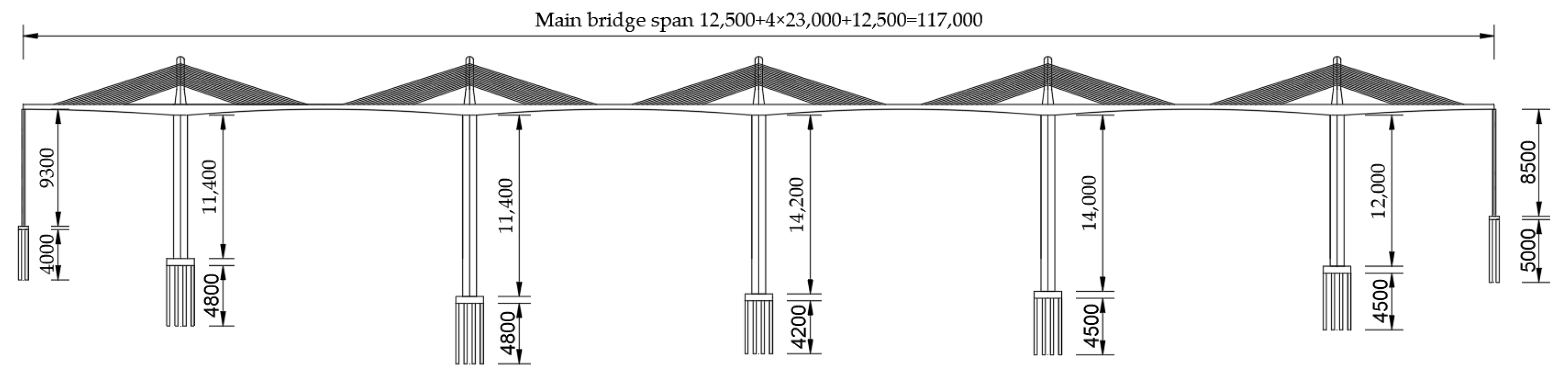
The large-span, high-pier, curved, partially cable-stayed bridge analyzed in this study is a prestressed concrete structure with a length of 1170 m. The main bridge span configuration is (125 + 4 × 230 + 125) m with a tower-pier-beam fixed rigid frame system. The height of the tower above the bridge deck is 36 m, and the tower column has a solid cross-section. The longitudinal bridge to the tower column up to 12 m above the bridge deck is a gradient section. The width changes from 6 m to 9 m in a straight line, and the upper tower column has an equal cross-section with a width of 6 m. The bridge deck has four lanes in both directions, with a width of 29.5 m and a design speed of 100 km/h. The layout of the main bridge is shown in Figure 1.
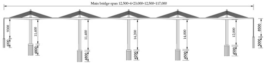
Figure 1.
The layout of the main bridge (mm).
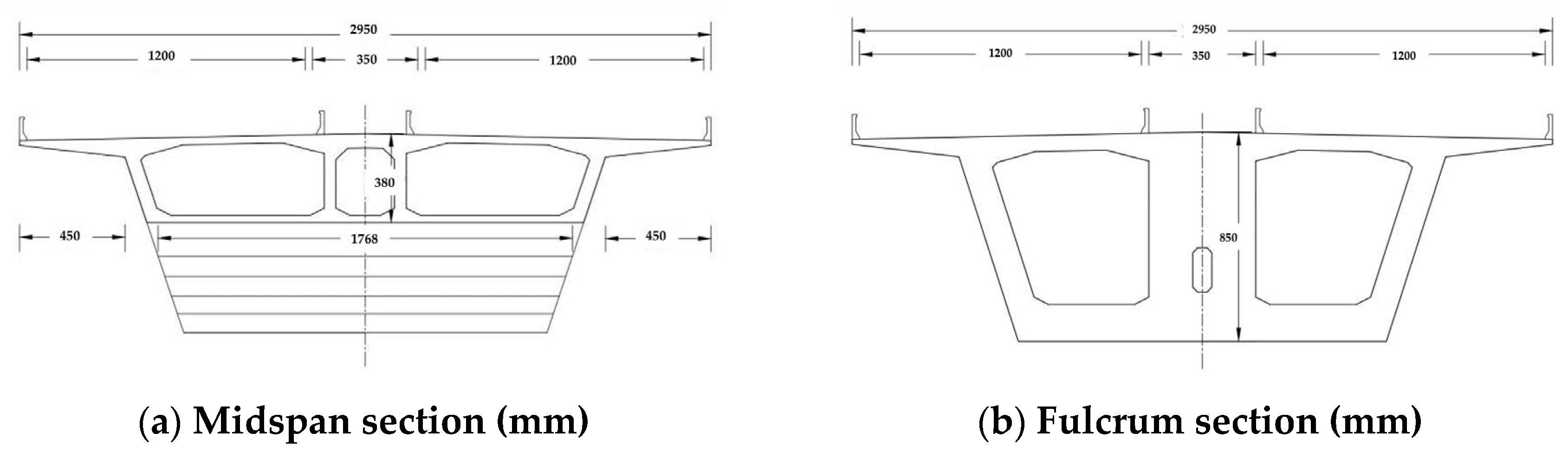
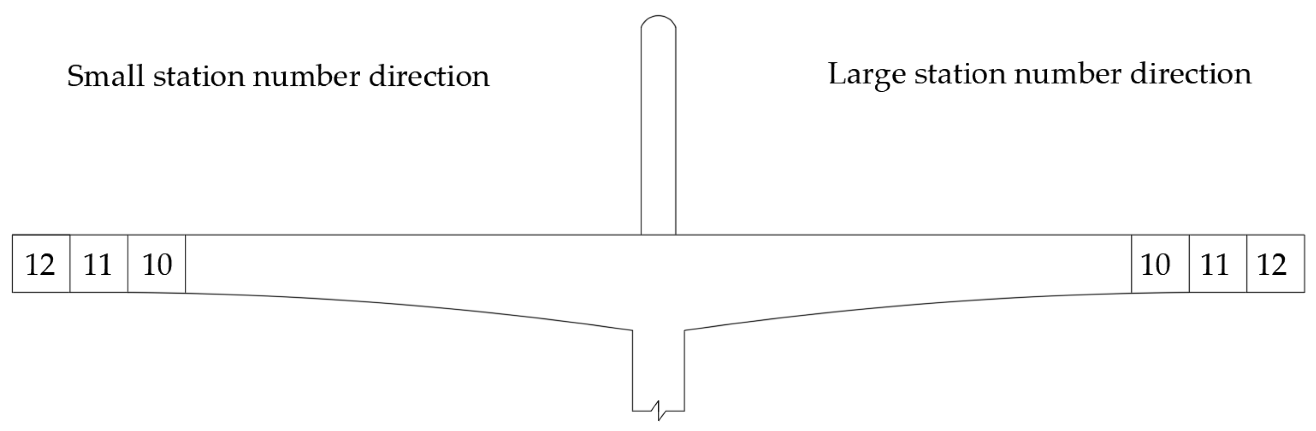
The main girder is a prestressed concrete structure with a large cantilever of different heights and a single box with three chambers and an oblique web section, as shown in Figure 2. The box girder consists of C55 concrete with varying cross-sectional dimensions, as shown in Figure 3.
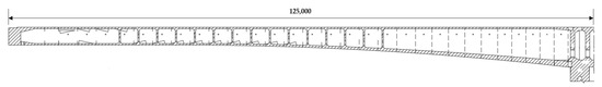
Figure 2.
Schematic diagram of main girder (mm).
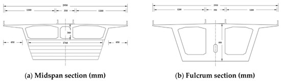
Figure 3.
Main girder cross-section (mm).
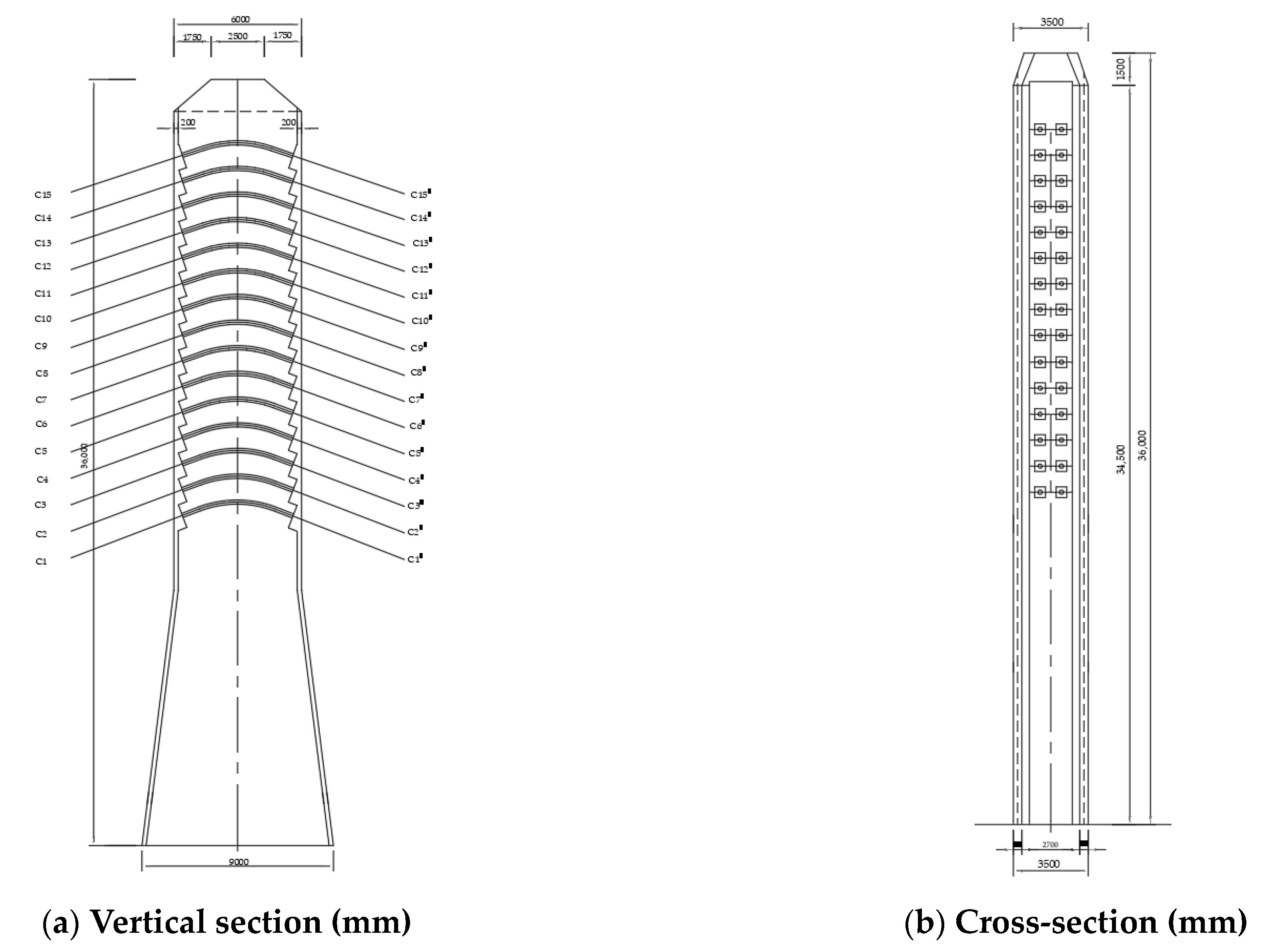
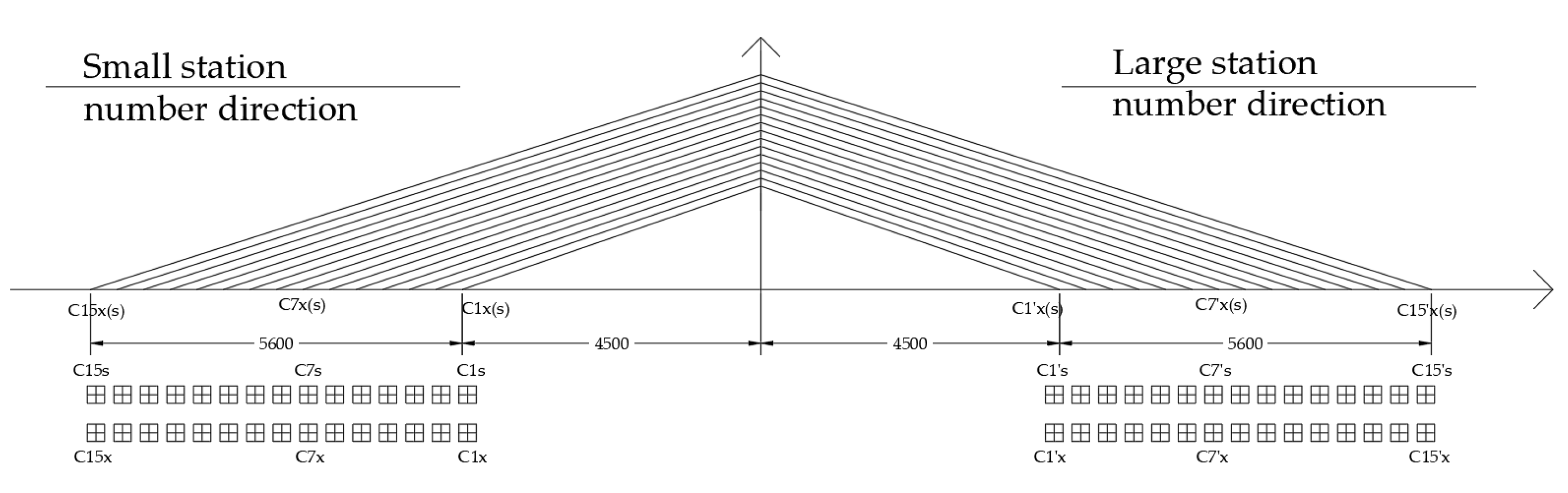
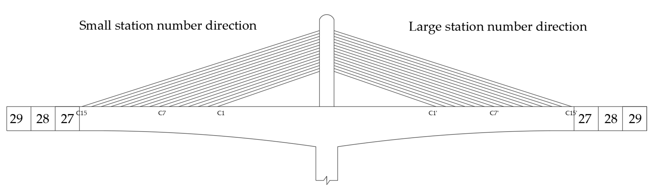
The main tower and main girder use a fixity system, with the tower height above the bridge deck of 36 m. The cross-section of the main tower is shown in Figure 4. The stay cables have a central double-plane configuration, with two rows in the central separator of the main girder, as shown in Figure 5. Each tower has 15 pairs of stay cables (with 150 cables for the entire bridge). The cables consist of s15.2 mm epoxy-coated prestressed steel strands, and the dimensions of the diagonal cables are 43 − s15.2 mm, with a standard strength of 1860 MPa and a modulus of elasticity of 1.95(±0.05) × 105 MPa. The configuration of the stay cables is shown in Figure 6.
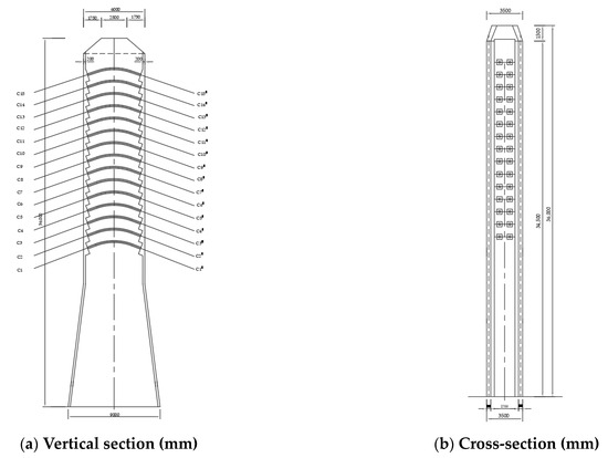
Figure 4.
Main Tower Schematic (mm).
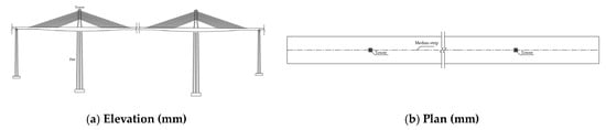
Figure 5.
Diagram of the cable (mm).
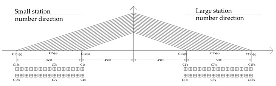
Figure 6.
The configuration of the main bridge’s stay cables (mm).
The main piers are double thin-walled hollow piers with an octagonal shape, as shown in Figure 7. The spacing between the two legs is 2 m. The hollow pier transverse to the wall has a thickness of 0.7 m, and the longitudinal bridge to the side of the wall has a thickness of 0.9 m. The middle wall thickness is 0.6 m. The cross-sections of the 30 × 30 cm chamfer, pier top, and pier bottom are 2.0 m thick and solid, with a 5 m variable-thickness section in the transition area. The heights of the main piers are as follows: 114 m (pier 10#), 144 m (pier 11#), 142 m (pier 12#), 140 m (pier 13#), and 120 m (pier 14#).
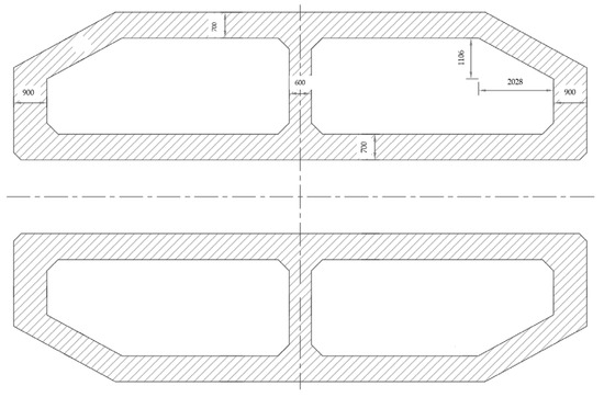
Figure 7.
Main pier cross-section (mm).
3.1. Finite Element Model Parameters
The simulation modeling of the partially cable-stayed bridge was performed using MIDAS/CIVIL software [31]. The bridge has 1311 nodes and 1138 elements. The main girder, main piers, and main towers are modeled using beam elements, while the stay cables are simulated using cable elements. The cable loads are applied by assigning the cable elements to the cable load condition. The cable loads are 4700 kN, and the prestressing force is considered by simulating the tensioning of the prestressed steel bars in the model. The prestressing load is 1395 MPa. The mechanical properties of the bridge are listed in Table 1 and Table 2. The longitudinal slope of the main girder is considered, and a single main girder model is used. The stiffness and mass of the bridge deck system are evenly distributed to the beam elements of the main girder. The main girder and stay cables are connected rigidly. The main girder, main piers, and main towers are connected rigidly. The bottom of the main pier uses general supports, restraining all translational and rotational movements, i.e., fixed constraints. The finite element types and mesh sizes are listed in Table 3.

Table 1.
Mechanical properties of concrete.
Table 2.
Mechanical Properties of prestressing steel.
Table 3.
Finite element types and mesh sizes.
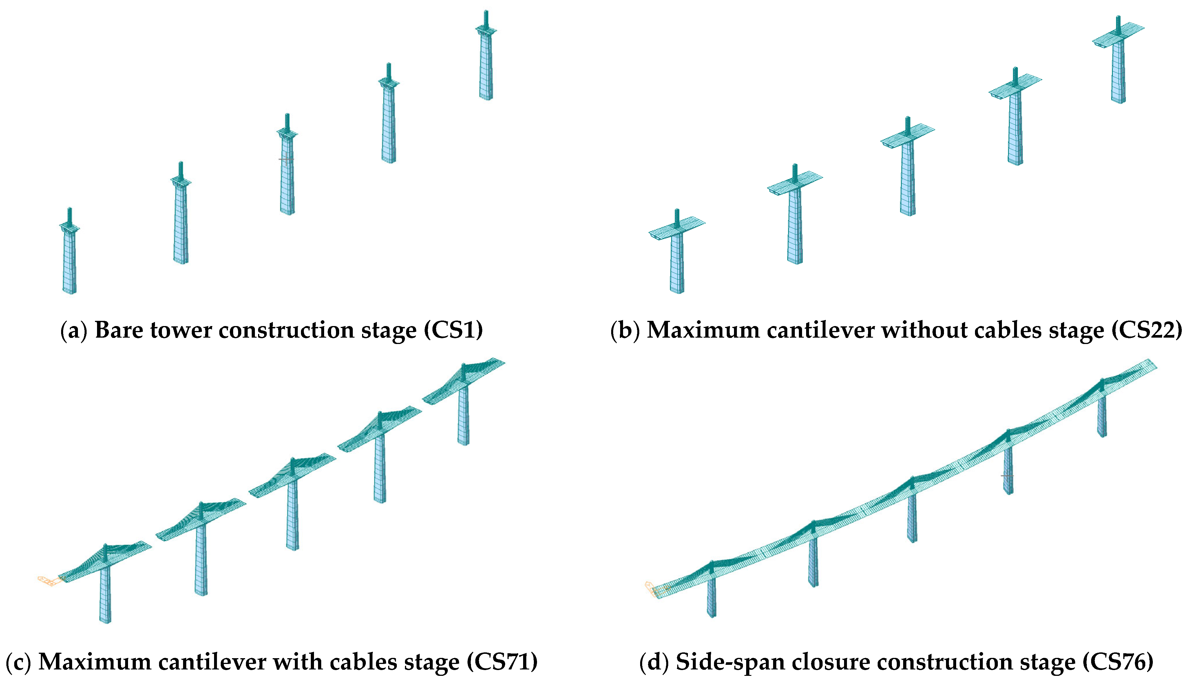
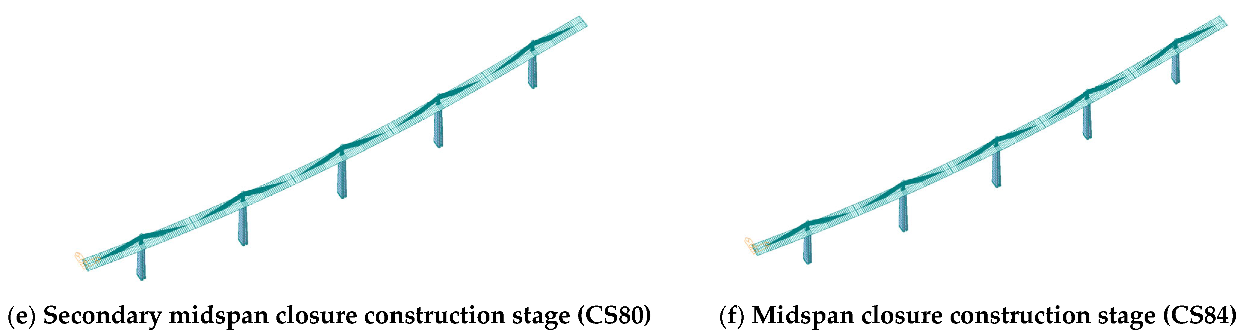
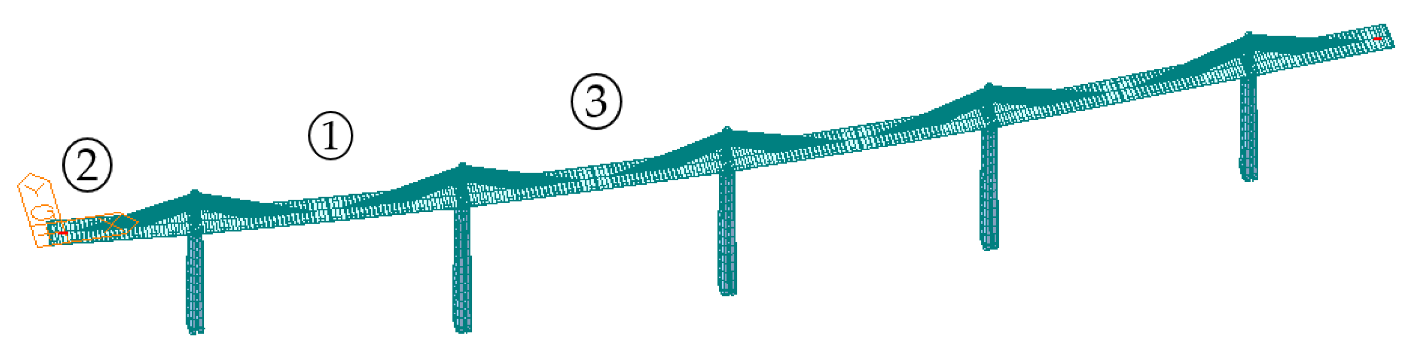
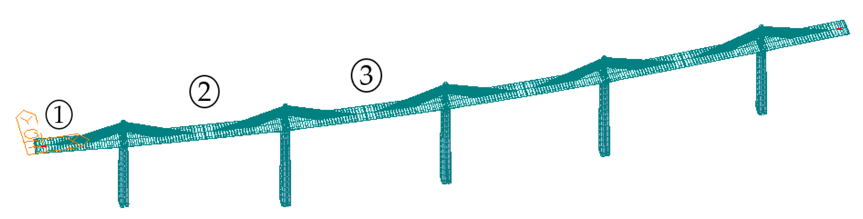
Based on the construction plan, 87 construction stages are simulated, with the main stages shown in Figure 8 and Figure 9. The cantilever formwork load (including the formwork and equipment) is 2000 kN; the hanging basket load (including the formwork and equipment) is 1000 kN; the secondary phase paving load is 164 kN/m; the side-span closure weight is 2626 kN; the secondary midspan closure weight is 175.1 kN; the midspan closure weight is 175.1 kN. The values are converted to unit-distributed loads and applied to the construction stages.
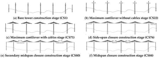
Figure 8.
Bridge construction stages.
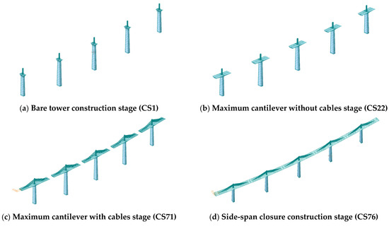

Figure 9.
Finite element models for major construction phases.
3.2. Calculation Conditions
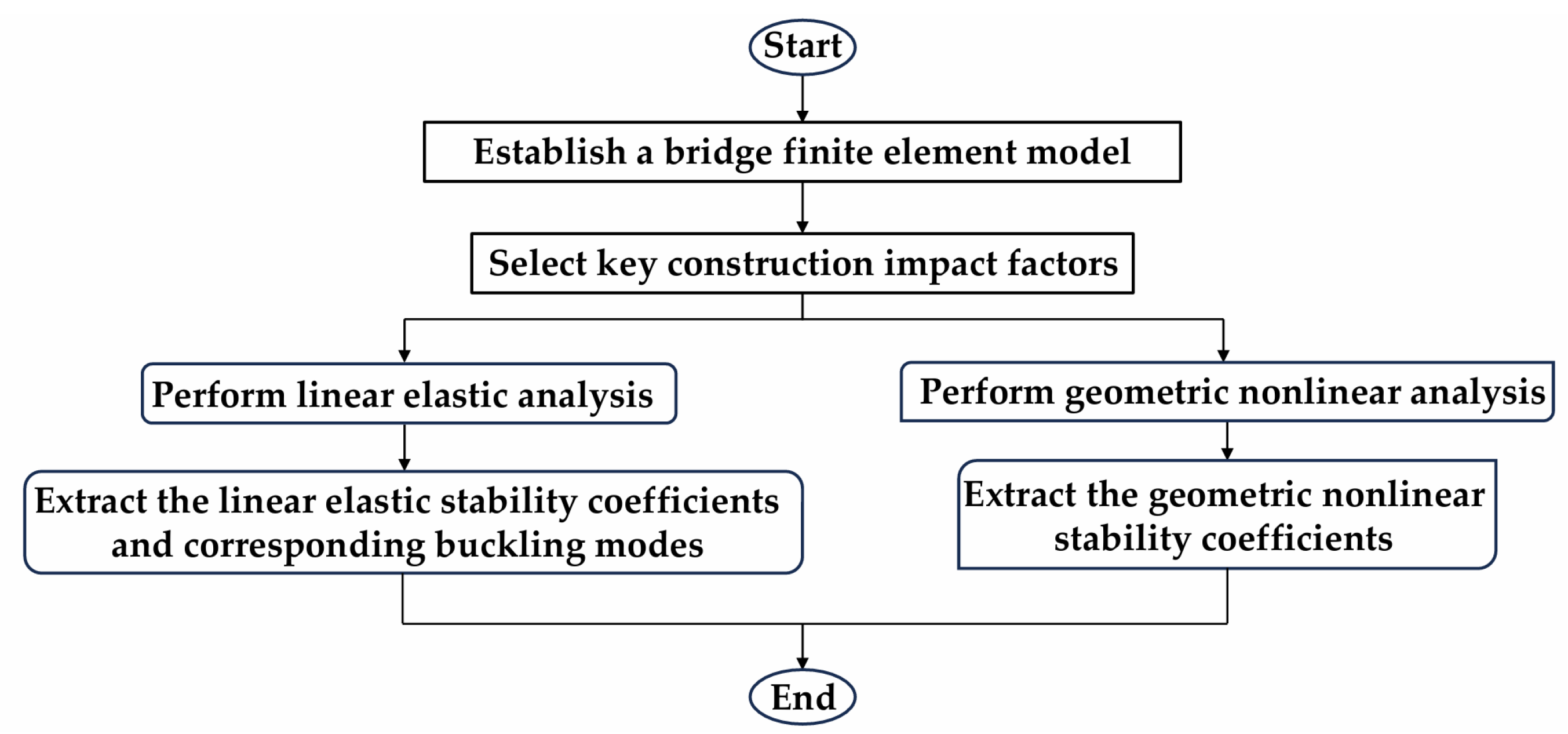
This study analyzes the stability of a partially cable-stayed bridge. Initially, a finite element model for the entire construction process was established. After establishing the construction sequence and selecting critical construction stages, the bridge’s stability was investigated, and the stability coefficients (reflecting the structure’s ability to maintain its equilibrium state when subjected to external loads and internal stresses) and buckling modes (reflecting changes in the bridge’s equilibrium state under external loads) were calculated in each stage. The impacts of various factors on the structure were analyzed. We considered the static wind load, asymmetrical construction of the main girder, closure sequence, hanging basket load, and hanging basket falling off. Linear elastic stability analysis, also known as eigenvalue buckling analysis, does not consider structural nonlinearity. However, the influence of geometric nonlinearity is significant during the construction of high-pier, large-span, partially cable-stayed bridges. Therefore, linear elasticity (changes in system forces due to structural dislocations resulting in a linear force-displacement relationship) and geometric nonlinearity (the dislocation of the structure causes a significant change in the system’s forces, resulting in a nonlinear relationship between force and displacement) should be considered in the stability analysis of this bridge type during construction. Plastic deformation should not occur during the construction of partially cable-stayed bridges, and the structural system should operate within the linear range [32]. Consequently, this study investigates the geometric nonlinearity of partially cable-stayed bridges. The technical approach of this study is illustrated in Figure 10.
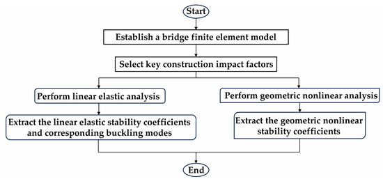
Figure 10.
Technical approach for structural stability analysis.
4. Stability Analysis Results
4.1. Design and Construction Sequence
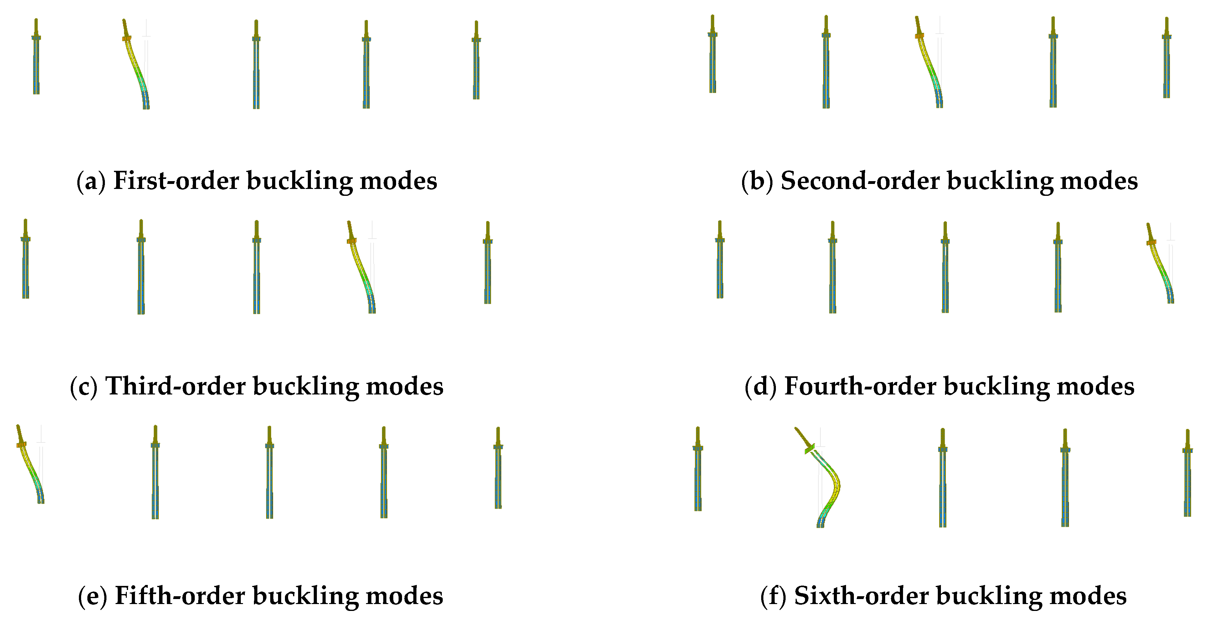
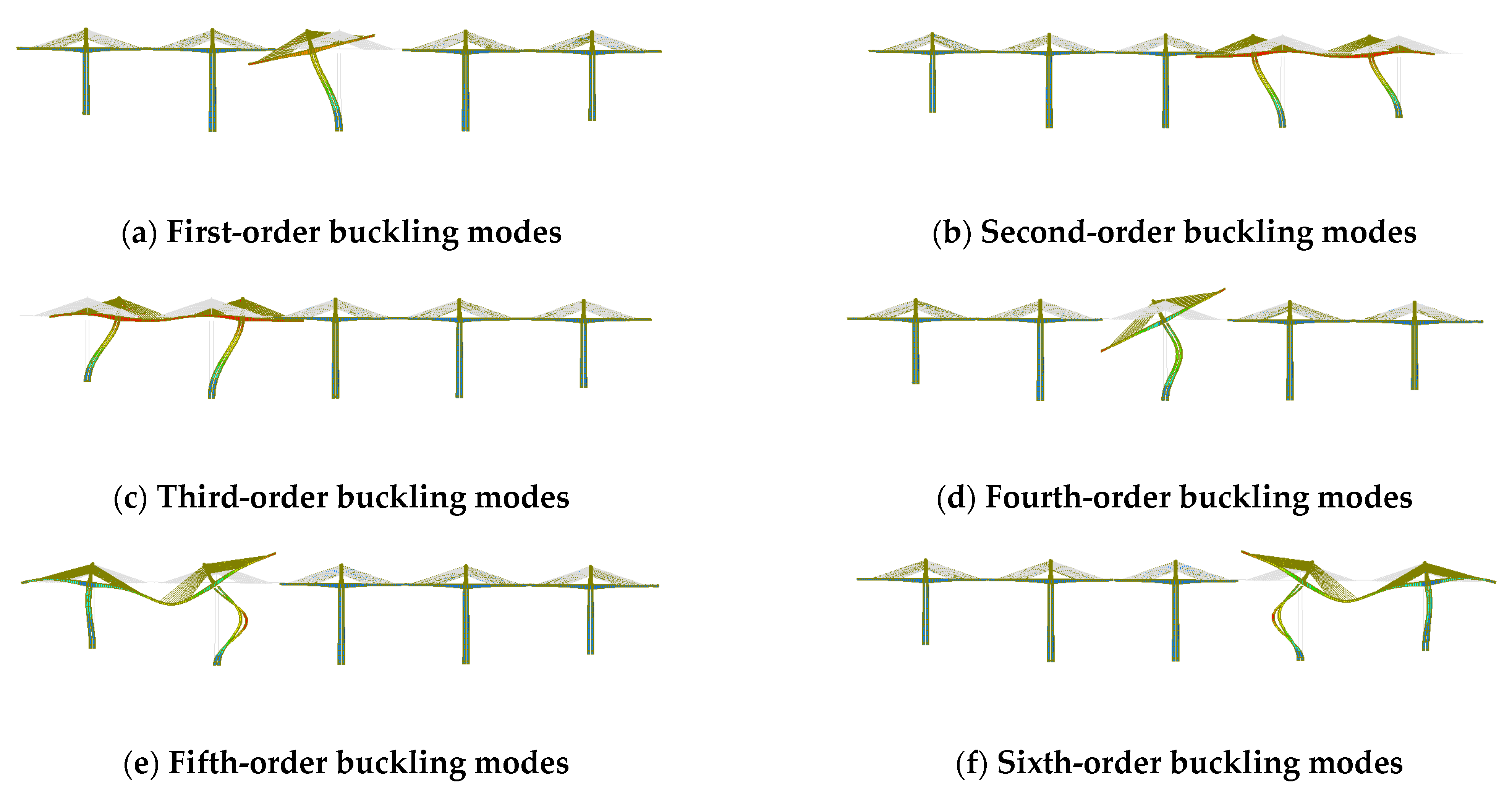
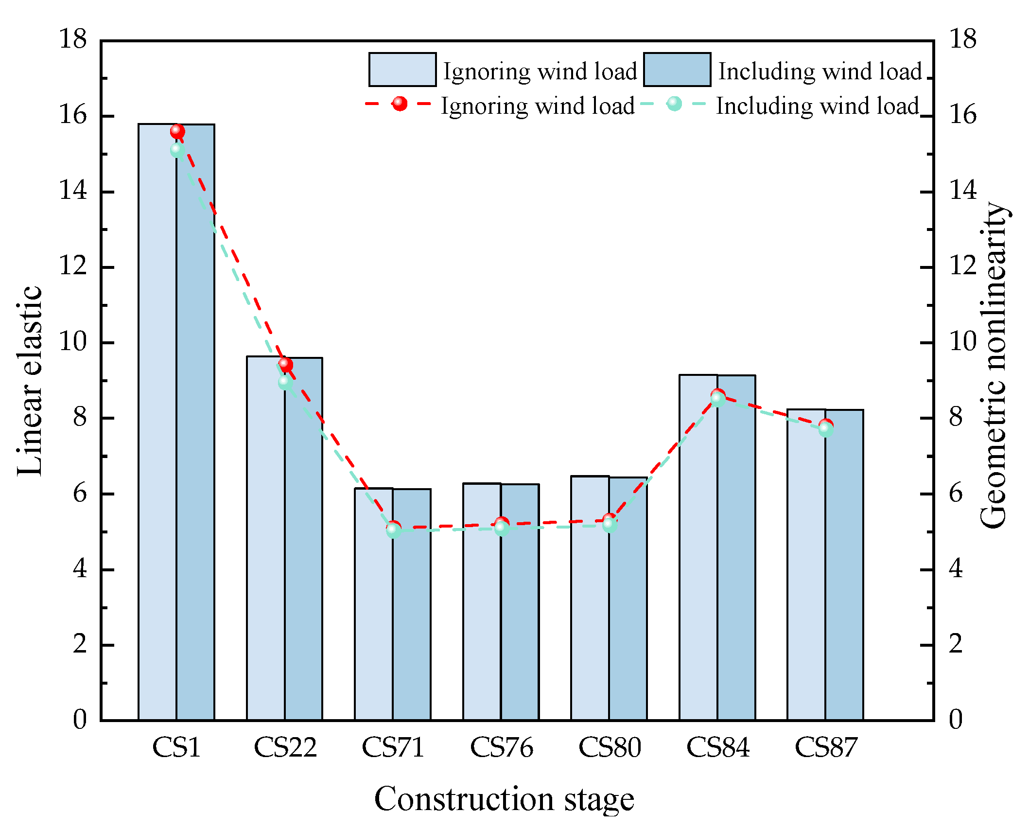
The forces and buckling modes during the construction were comprehensively considered. We selected the following stages for linear elastic and nonlinear stability analysis: bare tower construction stage CS1, maximum cantilever without cables stage CS22, maximum cantilever with cables stage CS71, side-span closure stage CS76, secondary midspan closure stage CS80, midspan closure stage CS84, and phase II paving stage CS87. The buckling modes in the different construction stages are shown in Figure 11, Figure 12, Figure 13 and Figure 14, and the stability coefficients are shown in Figure 15. From CS1 to CS71, Pier 11# was the first to experience instability due to its maximum height. Therefore, pier 12# is subjected to a strong tensile force, followed by piers 12#, 13#, 14#, and 10#.
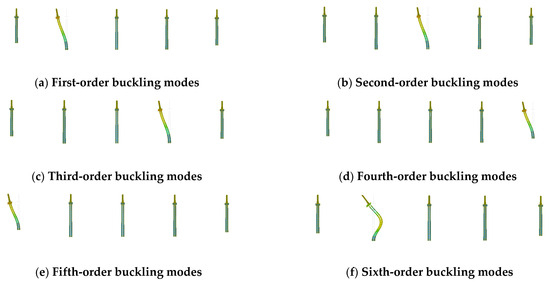
Figure 11.
CS1–CS71 first-sixth order buckling modes.
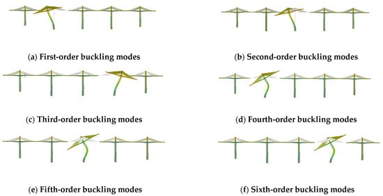
Figure 12.
CS76 first-sixth order buckling modes.
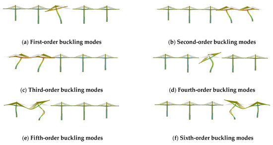
Figure 13.
CS80 first-sixth order buckling modes.
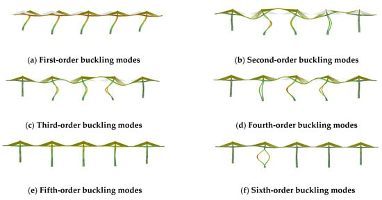
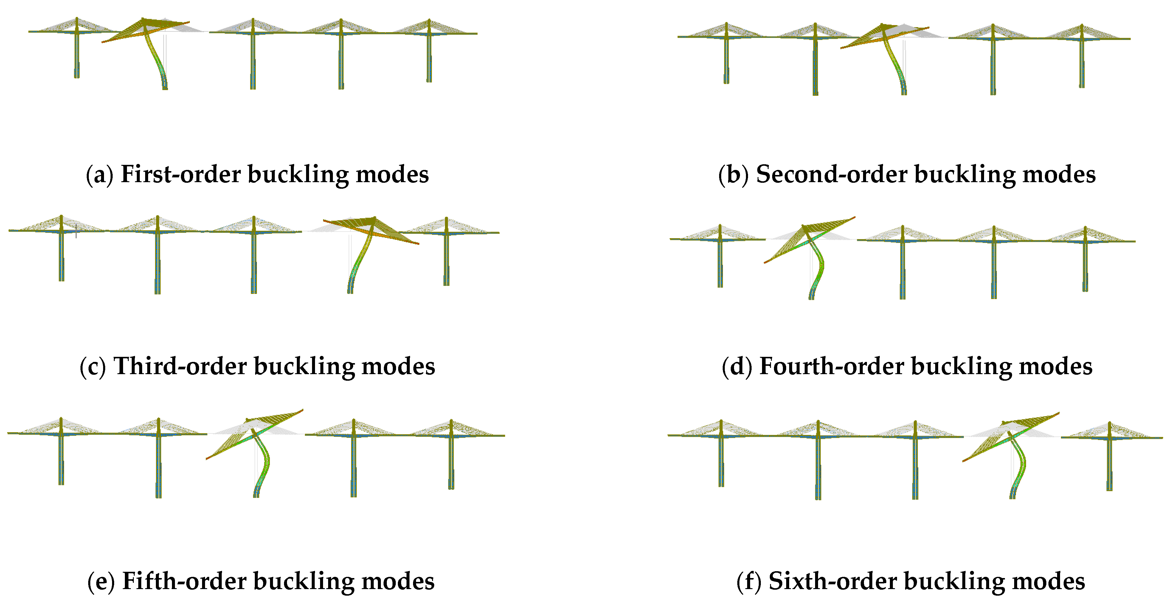
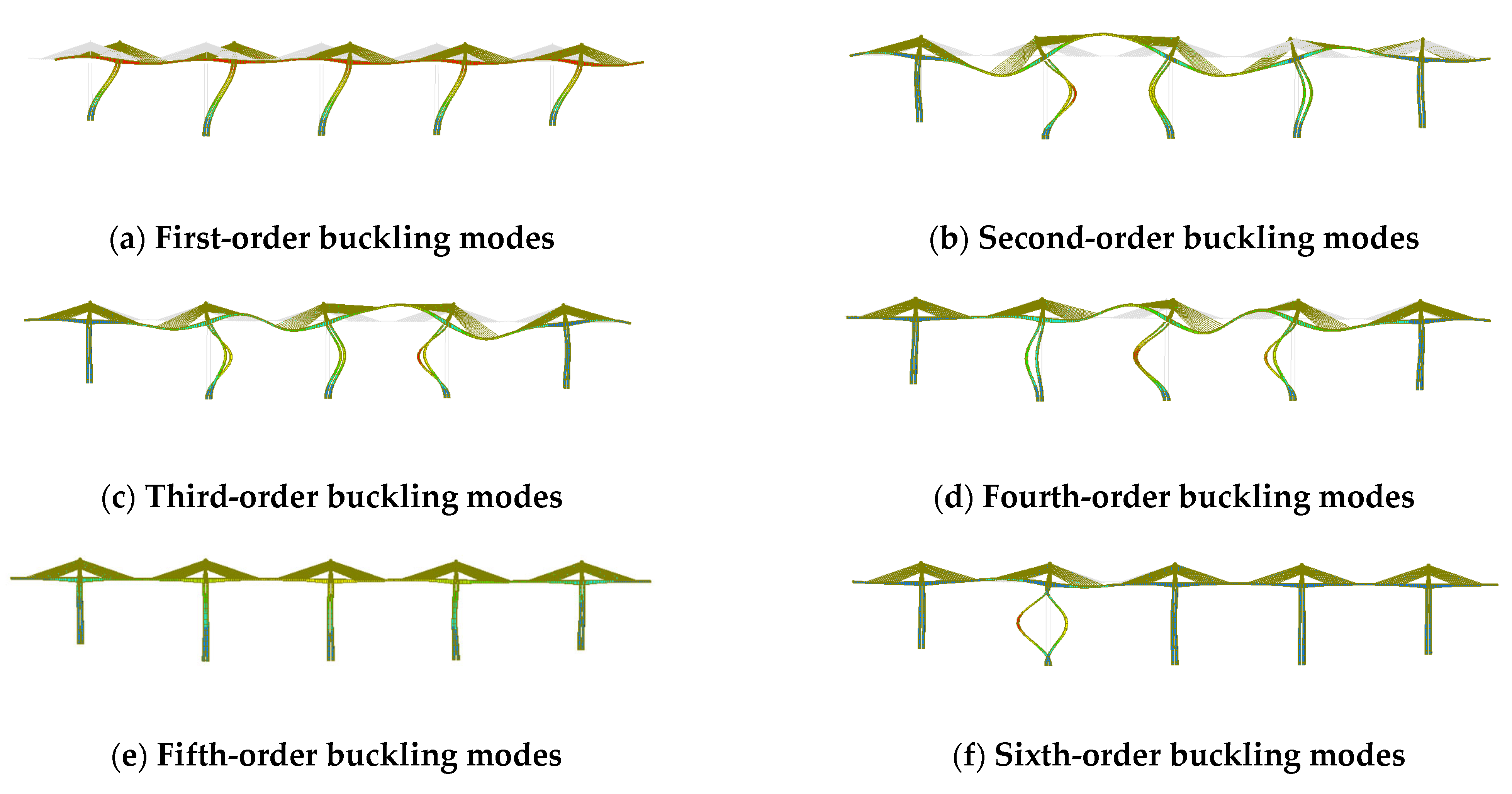
Figure 14.
CS84-CS87 first-sixth order buckling modes.
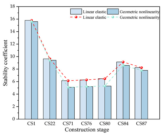
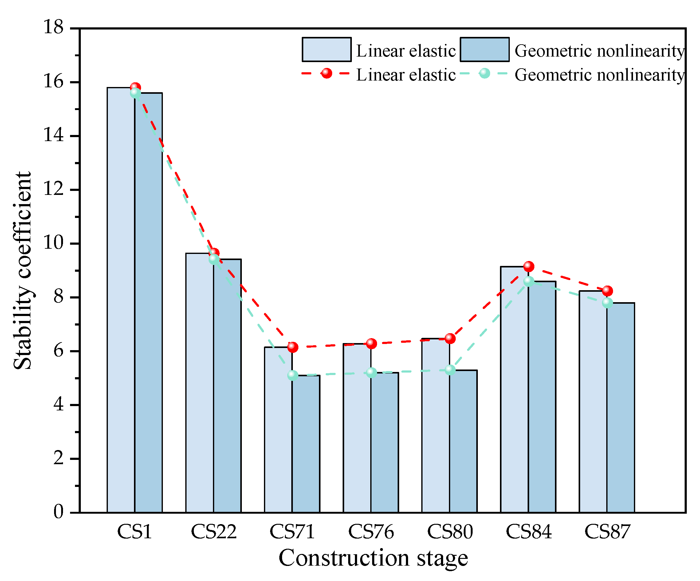
Figure 15.
Structural stability coefficients in different construction stages.
Figure 15 shows that the geometric nonlinear stability coefficient is 1.27% to 2.28% smaller than the linear elastic stability coefficient in the same stage. The reason is the high stiffness of the main piers and main towers, which significantly increases the structure’s stiffness during the casting of the symmetric cantilever of the main girder. Thus, the geometric nonlinear effects are minor when the main girder segments are limited. As the construction progresses from CS1 to CS71, the geometric nonlinear stability coefficient decreases as the number of main girder segments increases. After the main girder closure begins, the structural system changes, increasing the bridge’s stability. The geometric nonlinear stability coefficient increases by 65.38% from CS76 to CS84, showing that the closure of the main girder significantly improves geometric nonlinear stability. The stage from cantilever casting to the maximum number of cantilevers with cables is the most unfavorable construction phase and has the smallest stability coefficient. Therefore, it is advisable to avoid stopping construction at CS71.
4.2. Factors Influencing Construction
4.2.1. Impact of Static Wind Load
According to the design drawings and the “JTG/T 3360-01-2018 Wind-resistant Design Specification for Highway Bridges” [33], the surface roughness at the bridge site is Level D, the surface roughness coefficient , and the wind speed for a 100-year return period in the area is 26.8 m/s. According to the “JTG/T 3360-01-2018 Wind-resistant Design Specification for Highway Bridges” the transverse direction equivalent static wind load and longitudinal direction equivalent static wind load for the main girder, main tower, main pier, and stay cables are listed in Table 4.
Table 4.
Equivalent static wind loads.
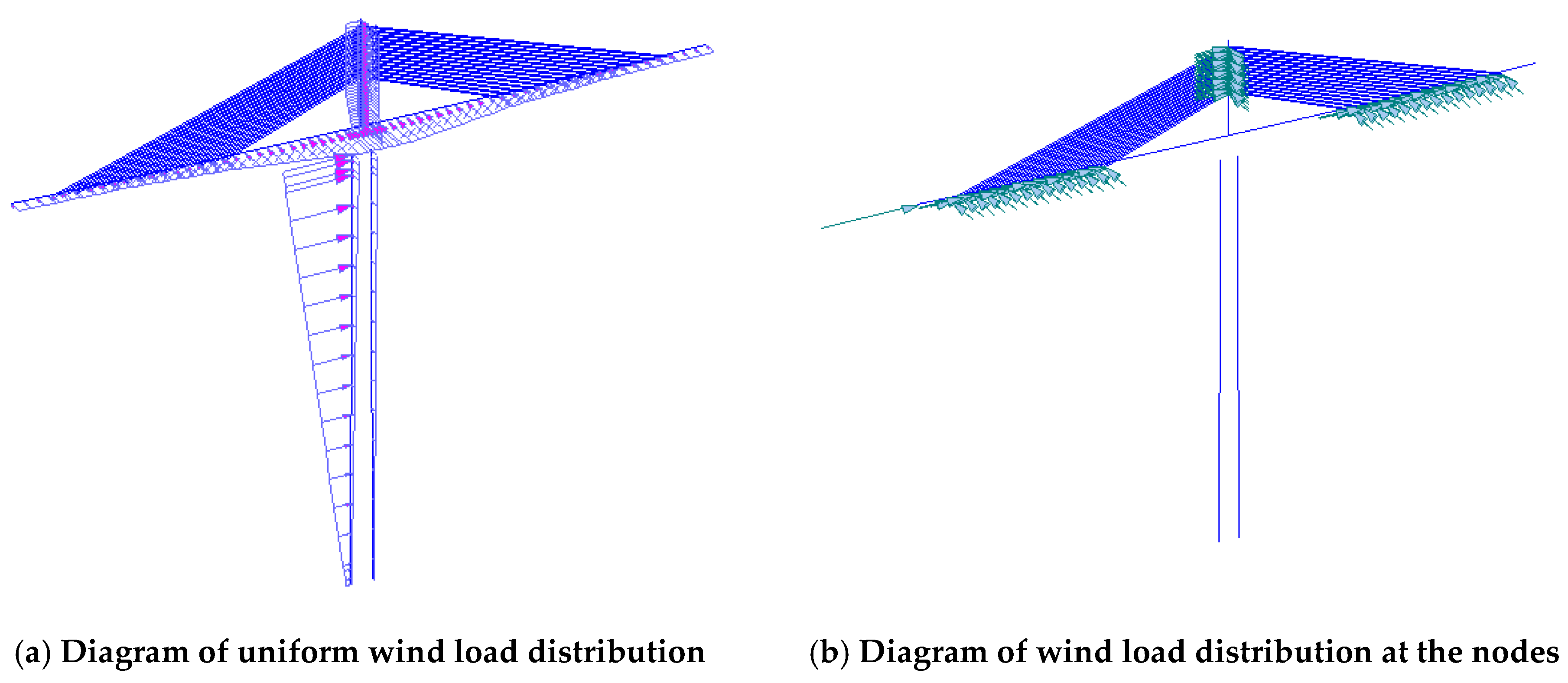
According to the data in Table 4, a static wind load is applied. The equivalent static wind loads for the main girder, main pier, and main tower are uniform loads. For the main girder, the equivalent static wind load in the transverse direction decreases from the root to the midspan end. For the main pier, the equivalent static wind loads in the transverse and longitudinal directions increase from bottom to top. For the main tower, the equivalent static wind load in the transverse direction decreases from the bottom to the top due to the reduction in the windward cross-sectional area. The equivalent wind load in the longitudinal direction decreases from bottom to top as the windward cross-sectional thickness decreases. The equivalent static wind load on the stay cables is evenly distributed and applied at both ends of the cables. An example of the wind load on the bridge structure for Pier 11# is shown in Figure 16.

Figure 16.
Static wind load of the main girder at pier 11# during the stay cable cantilever stage.
The buckling analysis shows that the first-order buckling modes in CS1, CS22, CS71, and CS76 result in longitudinal instability at Pier 11#. The first-order buckling mode in CS80 results in longitudinal instability at pier 12#, and the first-order buckling modes in CS84 and CS87 cause overall longitudinal instability. The stability coefficients in different stages are shown in Figure 17.
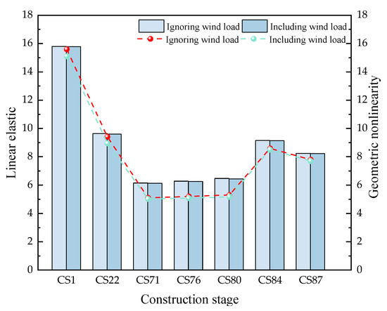
Figure 17.
Structural stability coefficient under a static wind load.
Figure 17 shows that the impact of a static wind load on the structural linear elastic stability coefficient is minimal. The reason is that the structure’s main pier is tall, and the primary instability mode is longitudinal instability of the main pier. The geometric nonlinear stability coefficient of the structure decreases, with the most significant reduction from CS1 to CS22, resulting in a decrease of 4.99% due to the wind load. During the construction of the main girder from CS1 to CS71, the influence of the wind load on the linear elastic stability coefficient increases, but its effect weakens after the girder is closed. Conversely, the effect of the wind load on the geometric nonlinear stability coefficient decreases from CS22 to CS71. Therefore, the effect of the wind load from CS1 to CS71 should be considered. The linear elastic stability coefficient remains above 4.0, and the geometric nonlinear stability coefficient stays above 2.5 during all construction stages, indicating that the structure is stable.
In summary, the impact of the wind load on the structural linear elastic stability coefficient of the partially cable-stayed bridge during construction is approximately 1%, while the effect on geometric nonlinearity is about 5%. The impact of the wind load should be considered from CS1 to CS71 when the stability coefficient exhibits the largest changes.
4.2.2. Impact of Asymmetrical Construction of the Main Girder
Asymmetrical construction may occur during the cantilever construction stage when the left and right sides of the main girder are constructed out of sync. Therefore, an analysis of the main girder was conducted, considering the maximum cantilever conditions without and with cables of pier 11# and its superstructure. The construction stages are categorized as follows: sections 10–12# represent the construction phase without cables, and sections 27–29# represent the construction phase with cables, these are shown Figure 18 and Figure 19. The sequence of concrete pouring on the left and right sides of the main girder was used to simulate asymmetrical construction. The working conditions are listed in Table 5.
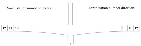
Figure 18.
Schematic diagram of asymmetric construction in the main girder without cables.
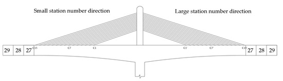
Figure 19.
Schematic diagram of asymmetric construction in the main girder with cables.
Table 5.
Calculation conditions for asymmetric construction of the main girder.
The buckling analysis indicates that pier 11# is the most unstable due to its height and the weight of the hanging basket. Thus, longitudinal instability of Pier 11# occurs in working conditions 1–6. The structural stability results for the main girder in the asymmetrical construction of the main girder with and without cables are shown in Figure 20.
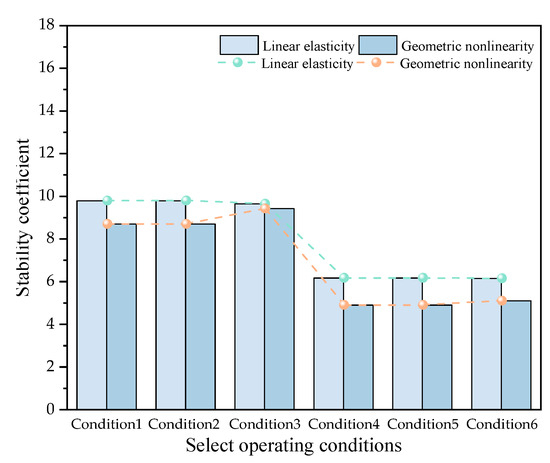
Figure 20.
Stability coefficients for CS22 and CS71.
When the main girder is constructed symmetrically in CS22 (condition 3) from both ends, the linear elastic and geometric nonlinear stability coefficients of the structure are 9.64 and 9.42, respectively. When asymmetric construction occurs at both ends of the main girder, the linear elastic stability coefficient is slightly higher, and the geometric nonlinear stability coefficient is slightly lower. The geometric nonlinear stability coefficient is 7.64% lower in conditions 1 and 2 than in condition 3. The reason is the longitudinal instability of Pier 11# in CS22. In the linear elastic stability analysis, conditions 1 and 2 have one less segment on the right side of the main girder at pier 11# compared to condition 3, resulting in a lower structural load of pier 11# and higher pier stability. The asymmetry of the main girder at both ends in conditions 1 and 2 increases the risk of structural instability and results in lower geometric nonlinear stability. Similarly, when the main girder is constructed symmetrically at both ends in CS71 (condition 6), the linear elastic and geometric nonlinear stability coefficients are 6.15 and 5.10, respectively. When asymmetric construction occurs at both ends of the main girder, the linear elastic stability coefficient is slightly larger, but the geometric nonlinear stability coefficient is 3.92% lower in conditions 4 and 5.
Although different asymmetric construction methods are used for the main girder in CS22 and CS71, the stability coefficients are identical in the same construction stage. This result indicates that the structural stability of the main bean in CS22 remains unchanged as long as the analysis stage is the same, despite the differences in asymmetric construction methods.
It can be concluded that during the cantilever casting construction of the main girder, the structural stability remains unchanged if the analysis stage is the same, regardless of the construction methods. Asymmetric construction reduces the geometric nonlinearity of the structure, decreasing stability. Therefore, it is essential to utilize symmetrical construction on both sides of the main girder to enhance the structure’s stability during the construction phase. Since asymmetric construction increases the risk of structural instability during the construction phase without cables, these situations should be avoided.
4.2.3. The Impact of Closure Sequence
In multi-tower partially cable-stayed bridges, the closure sequence can impact the structure’s displacement, internal forces, and the technical difficulty of construction. This study considers four closure schemes for the curved partially cable-stayed bridge and conducts stability analyses of the effects of the structure’s self-weight, the hanging basket, and the wet weight. Four closure schemes are shown Figure 21, Figure 22, Figure 23 and Figure 24.

Figure 21.
Schematic diagram of closure sequence for scheme 1.
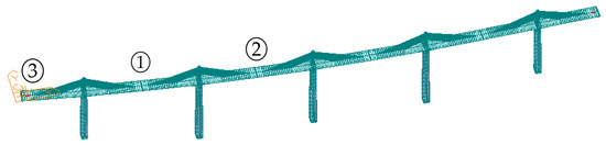
Figure 22.
Schematic diagram of closure sequence for scheme 2.
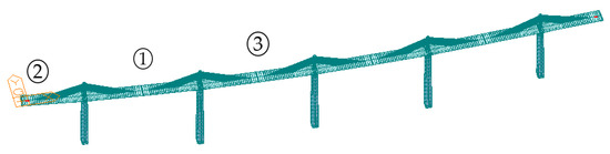
Figure 23.
Schematic diagram of closure sequence for scheme 3.

Figure 24.
Schematic diagram of closure sequence for scheme 4.
Scheme 1: CS84→System transition→CS80→System transition→CS76;
Scheme 2: CS80→System transition→CS84→System transition→CS76;
Scheme 3: CS80→System transition→CS76→System transition→CS84;
Scheme 4: CS76→System transition→CS80→System transition→CS84;
The structural stability and instability modes in each closure stage are analyzed by adjusting the closure construction sequence of the main girder and accounting for displacement and stress accumulation effects during the construction stages.
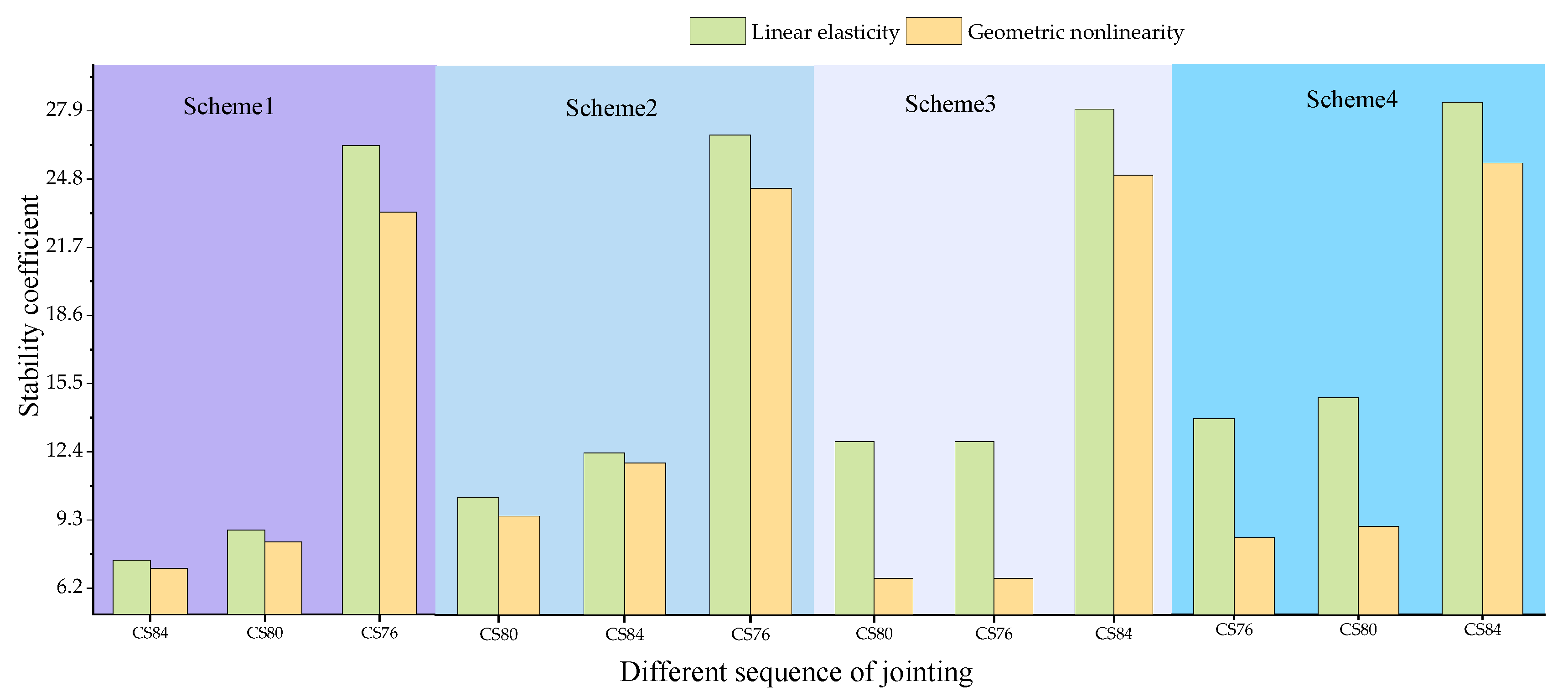
As shown in Figure 25, in scheme 1, the linear elastic and geometric nonlinear stability coefficients of the structure increase by 18.50% and 16.90% from CS84 to CS80 and by 195.85% and 180.72% from CS80 to CS76, respectively. In scheme 2, the linear elastic and geometric nonlinear stability coefficients increase by 38.00% and 56.60% from CS80 to CS84 and by 195.71% and 180.72% from CS84 to CS76, respectively. In scheme 3, the stability coefficients remain unchanged from CS80 to CS76, but they increase by 42.40% and 62.26% from CS76 to CS84, respectively. In scheme 4, the linear elastic and geometric nonlinear stability coefficients increase by 3.03% and 1.92% from CS76 to CS80 and by 41.42% and 62.26% from CS80 to CS84, respectively.
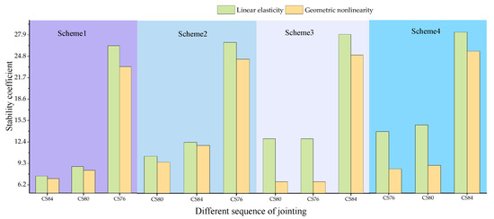
Figure 25.
Effect of closure sequence on stability coefficients.
In scheme 1, longitudinal instability occurs at piers 11#, 12#, and 13# after the midspan closure and at piers 10# and 14# after the secondary midspan closure of the main girder. The side-span closure significantly improves structural stability due to constraints at both ends, and longitudinal instability occurs at Pier 11#. In scheme 2, the secondary midspan is closed first, and longitudinal instability occurs at Pier 12#. The subsequent midspan closure at Pier 12# causes longitudinal instability. The final side-span closure results in longitudinal instability. In scheme 3, the secondary midspan is closed first, causing longitudinal instability at Pier 12#. The subsequent side-span closure results in longitudinal instability at Pier 12#, and the final midspan closure results in longitudinal instability of the bridge. In scheme 4, the side span is closed first, with instability at Pier 11#. The subsequent secondary midspan closure causes longitudinal instability at Pier 12#, and the final midspan closure results in longitudinal instability of the bridge.
Scheme 1 indicates that structural instability always occurs in the central main girder due to the effects of self-weight, hoist basket load, and wet weight, increasing the construction difficulty of the secondary midspans and side-spans and making scheme 1 unsuitable. In contrast, in scheme 2, the secondary midspan is closed first, integrating the more unstable pier 11# with the relatively stable pier 10#. The instability causes the structural failure of the uncoupled pier 12#. Therefore, the stability coefficient factor of the secondary midspan closure is lower in Scheme 2 than in Scheme 1. During the midspan closure of scheme 2, longitudinal instability occurs, increasing the construction difficulty of the main girder in the side-span closure. Thus, scheme 2 is unsuitable. Scheme 2 results in higher structural stability than scheme 3. However, scheme 3 requires balancing the weights at both ends of the main girders on two piers (piers 10# and 11# and piers 13# and 14#) so that the side-span closure meets the conditions. In contrast, scheme 2 requires balancing the weights on five piers (piers 10#–14#). Thus, scheme 3 is superior to scheme 2. However, scheme 3 results in lower stability of the uncoupled pier 12# after the secondary midspan closure because the side spans are closed first. Therefore, scheme 3 is also unsuitable for construction. In contrast, scheme 4′s closure sequence progresses step-by-step, requiring a weight balance only on the pier closed at each step. This strategy reduces construction difficulty and better controls structural stability during construction than Schemes 1–3, improving construction efficiency. Therefore, scheme 4 results in the highest structural stability.
4.2.4. The Impact of the Hanging Basket Load
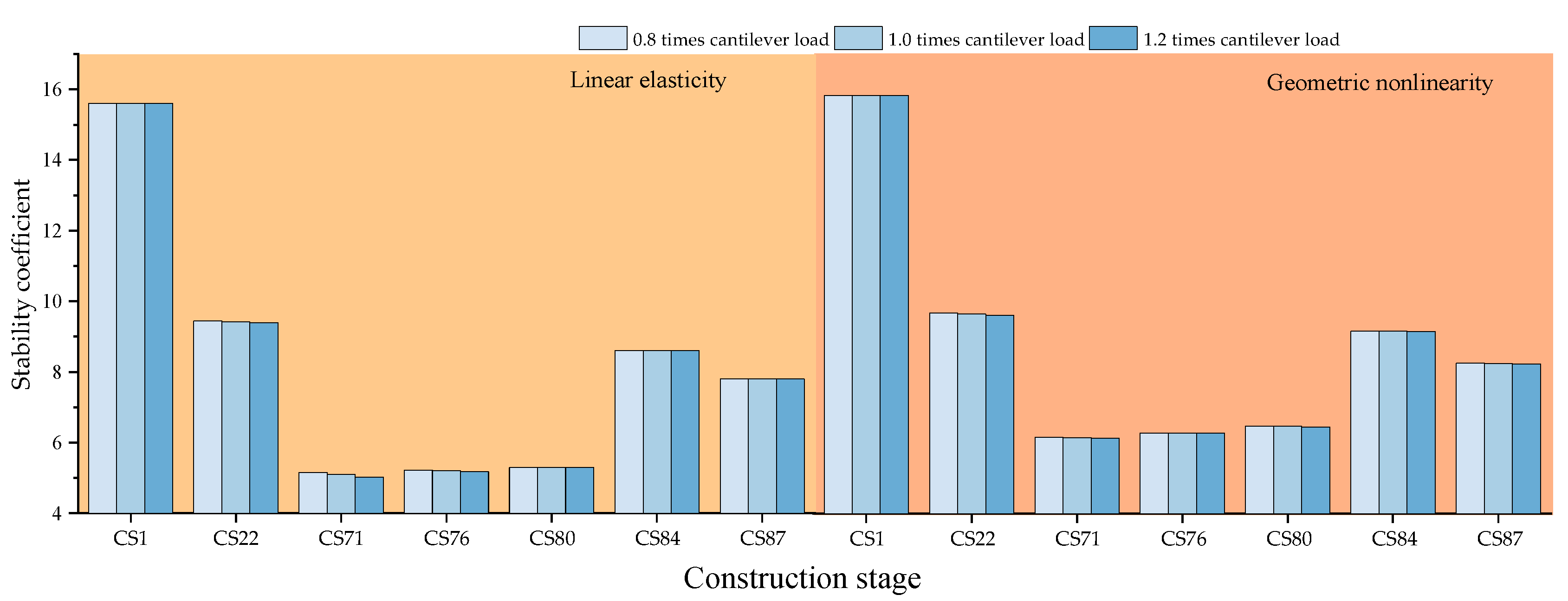
A discrepancy exists between the design and actual hanging basket loads during the construction of partially cable-stayed bridges. We consider this difference in cantilever construction and the effects of the dead and wet weights on the structure’s stability. Hanging basket loads may deviate due to construction errors or different loading conditions. Since the load can vary, we examine the effect on stability when the hanging basket load ranges from 0.8 times less than to 1.2 times the design load. The results of this analysis are shown in Figure 26.
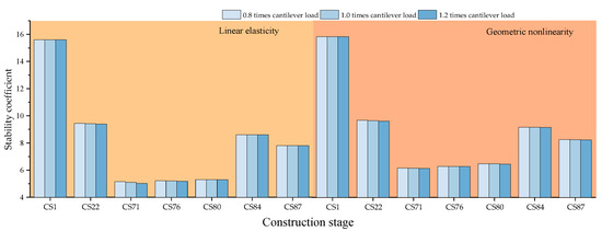
Figure 26.
Stability coefficient for different hanging basket loads.
A change in the hanging basket load changes the structural linear elastic stability coefficient by 1%. Reducing the hanging basket load increases the linear elastic stability of the structure and vice versa. The results are the same for the geometric nonlinear stability coefficient.
4.2.5. The Impact of the Detachment of the Hanging Basket
During the cantilever casting of the main girder in partially cable-stayed bridges, equipment aging, and improper operation by personnel may cause the detachment of the hanging basket. We consider the effects of self-weight, hanging basket load, and wet weight on the detachment of the basket and the structure’s stability.
We focus on the most critical phases, i.e., without and with cables. The stability analysis is performed for Pier 11#, considering the different conditions of the concrete blocks when the hanging basket falls off in working conditions 1–6. The conditions are listed in Table 6.
Table 6.
Calculation conditions for basket detachment.
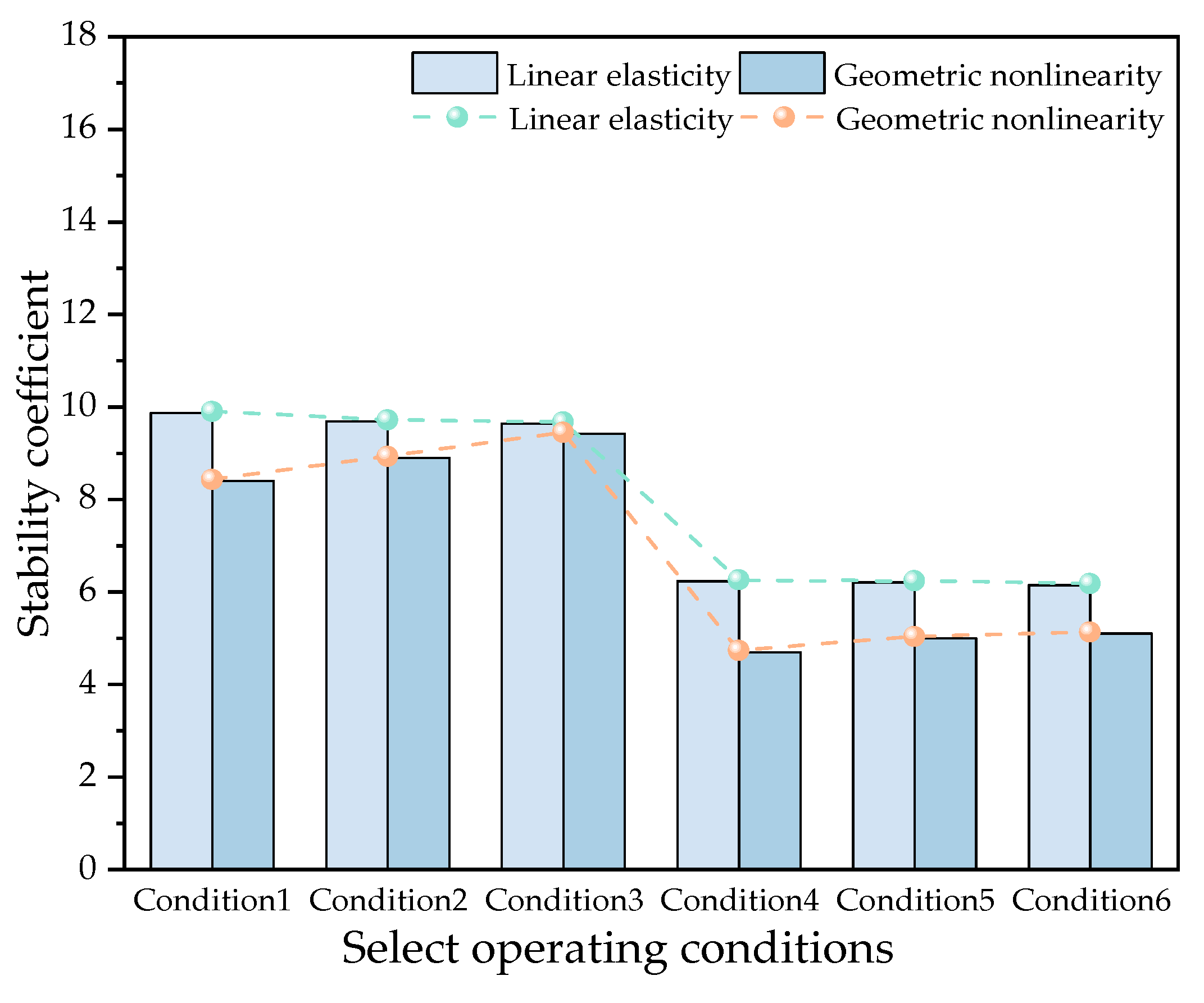
The condition is CS22 at segment 12# of the cantilever casting of the main girder without cables and CS71 at segment 29#. The stability coefficients for conditions 1–3 and 4–6 are shown in Figure 27.

Figure 27.
Stability coefficients for basket detachment in CS22 and CS71.
Basket detachment slightly increases the linear elastic stability coefficients in the construction with and without cables. The coefficients are 2.39% and 0.52% higher in conditions 1 and 2 without the cable stage and 1.30% and 0.96% higher in conditions 4 and 5 in the cable stage, respectively, than in conditions 3 and 6. However, basket detachment significantly decreases the geometric nonlinear stability coefficients, with reductions of 10.83% and 5.52% for conditions 1 and 2 in the without cable stage and 7.84% and 1.96% for conditions 4 and 5 in the cable stage compared to conditions 3 and 6.
During the cantilever casting of the main girder without cables, the influence of basket detachment on structural stability is within 6%. When the basket detachment causes the cast-in-place beam segments to fall, the effect on stability is within 11%. These incidents should be avoided to ensure safety during construction. During the cantilever casting of the main girder with cables, the impact of basket detachment on stability is within 2%. When the basket detachment causes the cast-in-place beam segments to fall, the impact is within 8%. Therefore, during the cantilever construction with cables, the structural safety of the beam segment baskets should be considered to prevent accidents resulting from basket detachment and the subsequent detachment of beam segments.
Based on the analysis of both construction stages, the following can be concluded:
(1) Basket detachment slightly improves the linear elastic stability of the structure. Since the failure of pier 12# is caused by longitudinal instability during the cantilever casting of the main girder, the detachment of the basket reduces the load applied by the main girder to the pier, resulting in a slight increase in the linear elastic stability coefficient of the structure.
(2) If one side of the basket is detached during construction, the main girder becomes asymmetrical at both ends, reducing structural stability and increasing the risk of instability failure. Measures should be taken to prevent this event during construction.
(3) The detachment of the basket and the cast-in-place beam segments has a greater impact on stability than the basket detachment. This occurrence should be prevented during construction.
5. Conclusions
This study used a large-span, high-pier, curved, partially cable-stayed bridge in Shaanxi Province as a case study and established a finite element analysis model to analyze the bridge’s stability during construction. The key conclusions are as follows:
(1) During the cantilever construction of the main girder, the five main piers experienced instability in the order of Pier 11#, Pier 12#, Pier 13#, Pier 14#, and Pier 10#. The stability can be improved by constructing the main girders of the piers in this sequence.
(2) The effect of a static wind load on the linear elastic stability coefficient of the structure was approximately 1%, whereas the influence on the geometric nonlinear stability coefficient was around 5%. The static wind load reduced the geometric nonlinearity of the structure, with a maximum reduction of 4.99%. The effect of the static wind load on the structure should be considered to ensure a safe construction process.
(3) During the cantilever casting of the main girder, asymmetric construction at both ends affected the linear elastic stability coefficient by approximately 1% and the geometric nonlinear stability coefficient by up to 8%. The geometric nonlinear stability coefficient was 7.64% and 3.92% lower in CS22 and CS71, respectively, than in normal construction. This finding highlights the increased risk of structural instability due to asymmetric construction, emphasizing the need to avoid it.
(4) During main girder construction, variations in the construction basket load within ±20% of the design value had a less than 1% impact on the structural stability coefficient. However, when the basket and the cast-in-place beam segments were detached, the influence on the stability coefficient was 11%. The geometric nonlinear stability coefficient was 10.83% and 7.84% lower in CS22 and CS71, respectively, than in normal construction, affecting the stability during construction. Therefore, it is crucial to inspect the reliability of the basket regularly during construction to prevent detachment and ensure stability.
(5) In scheme 4, the linear elastic and geometric nonlinear stability coefficients increased by 3.03% and 1.92%, respectively, from the side-span closure to the secondary midspan closure, with a further increase of 41.42% and 62.26% from the secondary midspan closure to the midspan closure. Scheme 4 provided the best stability control during the main girder construction.
Future studies can consider the effect of different parameters and combinations of parameters on the stability of different stages of a partially cable-stayed bridge from the perspective of design parameters.
Author Contributions
Conceptualization, L.W.; methodology, L.W.; software, H.Z. and L.K.; validation, L.W., H.Z., and Y.L.; formal analysis, H.Z.; investigation, L.K.; resources, L.W.; data curation, H.Z. and C.Z.; writing—original draft preparation, H.Z. and R.X.; writing—review and editing, H.Z.; visualization, C.Z.; supervision, L.W.; project administration, L.W.; funding acquisition, L.W. All authors have read and agreed to the published version of the manuscript.
Funding
This research was funded by the National Key Research and Development Program of China (Grant No. 2021YFB1600305); Natural Science Basic Research Program of Shaanxi (Program No. 2022JC-23); Innovation Capability Support Program of Shaanxi (Program No. 2023-CX-TD-38); Shaanxi Provincial Natural Science Foundation 2020JM-230 and Shaanxi Teacher Development Research Project (No. SJS2022ZQ019) which are gratefully acknowledged.
Data Availability Statement
The original contributions presented in the study are included in the article; further inquiries can be directed to the corresponding author.
Conflicts of Interest
The author, Lin Kang, is employed by Guangxi Zhonghe Expressway Co., Ltd. The remaining authors declare that there are no business or financial relationships that could be perceived as potential conflicts of interest in the course of the study.
Abbreviation
| Symbols and Acronyms | Implication |
| T.L. | Total Lagrange |
| U.L. | Updated Lagrange |
| Structural initial elastic stiffness matrix | |
| Structural initial geometric stiffness matrix | |
| Structural large displacement stiffness matrix | |
| Structural initial tangent stiffness matrix | |
| Nodal displacement | |
| Load increment | |
| Structural elastic stiffness matrix | |
| Structural geometric stiffness matrix | |
| Initial load | |
| Structural geometric stiffness | |
| Geometric stiffness matrix of the structure under critical loads | |
| Total load that can be sustained before instability occurs under condition i | |
| Design load under condition i | |
| Stability coefficient | |
| CS1 | Bare tower construction stage |
| CS22 | Maximum cantilever without cables stage |
| CS71 | Maximum cantilever with cables stage |
| CS76 | Side-span closure construction stage |
| CS80 | Secondary midspan closure construction stage |
| CS84 | Midspan closure construction stage |
| CS87 | Phase II paving stage |
References
- Mathivat, J. Recent development in prestressed concrete bridges. FIP Note 1988, 2, 15–21. [Google Scholar]
- Shiming, L.; Xiaoke, L.; Shunbo, Z. Study on Structural Design of Single-pylon Partial Cable-stayed Bridge. J. Henan Univ. 2016, 46, 724–731. [Google Scholar] [CrossRef]
- Hailin, L.; Peng, W.; Yun, H. Study on Key Parameters of Partially Cable-stayed Bridge Design Based on Research Data. Technol. Highw. Transp. 2024, 40, 62–69. [Google Scholar] [CrossRef]
- Jiayuan, Z.; Xuewei, W.; Ming, Z. Research on Methods to Determine Rational Completion State for Extradosed Bridge Based on Load Bearing Characteristics of Main Girder. World Bridges 2021, 49, 35–41. [Google Scholar]
- Liming, Z.; Qinyu, C.; Dashuai, L. Stay Cable Tension Optimization for Completed Extradosed Bridge Basedon Comprehensive Optimization Method. World Bridges 2024, 52, 88–93. [Google Scholar] [CrossRef]
- Wang, L.; Xi, R.; Guo, X.; Ma, Y. The Structural Design and Optimization of Top-Stiffened Double-Layer Steel Truss Bridges Based on the Response Surface Method and Particle Swarm Optimizations. Appl. Sci. 2023, 13, 11033. [Google Scholar] [CrossRef]
- Liang, H.; Bo, H.; Jiawen, L. Butterfly-Shape Stress Region and Its Rebars Optimization in Large-span Curved Extradosed Cable-stayed Bridge. Constr. Technol. 2023, 12, 58–63+87. [Google Scholar]
- Ali, K.; Katsuchi, H.; Yamada, H. Comparative Study on Structural Redundancy of Cable-Stayed and Extradosed Bridges Through Safety Assessment of Their Stay Cables. Engineering 2021, 7, 236–261. [Google Scholar] [CrossRef]
- Zongli, S.; Yuewu, Z. Research on design parameters of long-span railway concrete extradosed bridge. J. Railw. Eng. Soc. 2022, 39, 50–54+61. [Google Scholar]
- Wang, L.; Yu, S.; Liu, L.; Xiao, Z. Behavior of Multispan Extradosed Bridge Subjected to Variation of Cable-Free Segment Length. J. Eng. 2022, 2022, 7555127. [Google Scholar] [CrossRef]
- Zhang, Y.; Huang, W.; Tang, X. Sensitivity Analysis of the Main Structural Parameters of the Four-Tower Partially Cable-Stayed Bridge. Appl. Sci. 2023, 13, 3831. [Google Scholar] [CrossRef]
- Chunming, X.; Shengrong, L.; Chenguang, Z. Research on the Sensitivity Analysis of Structural Parameters for V-Shaped Short Towers With Cable-Stayed Bridges. Highway 2023, 68, 187–193. [Google Scholar]
- Huang, E.; Ke, H.; Hu, H. Optimization of Construction Process and Determination of Intermediate Cable Forces for Composite Beam Cable-Stayed Bridge. Appl. Sci. 2023, 13, 5738. [Google Scholar] [CrossRef]
- Jiawen, X. Construction technology of new hanging cable of unbonded steel strand for cable-stayed bridge of low tower. Highway 2023, 68, 157–162. [Google Scholar]
- Hong, L.; Jinghua, W.; Jingguo, L. Design and calculation of temporary consolidation structure of pier beams for construction of the main girders of low tower cable-stayed Bridges. Highway 2022, 67, 216–219. [Google Scholar]
- Zhichao, Y.; Peixin, W.; Shengchun, L. Comparative analysis of mechanical propertie of low tower cable-stayed bridge by two construction methods. Highway 2019, 64, 138–142. [Google Scholar]
- Mingyang, H.; Long, L.; Kaiqiang, Q. Study on the influence of delayed construction of cable-stayed cables on structural mechanical properties of cable-stayed Bridges with low towers. Highway 2022, 67, 152–155. [Google Scholar]
- Xiaojun, W.; Li, Z. Construction technology of “delayed tension of stay cable” for Hongxi Bridge. World Bridges 2020, 48, 37–41. [Google Scholar]
- Huiwu, J.; Zhanming, C.; Chunhua, Z. Construction technology of super wide box girder block 0 of cable-stayed bridge with low tower. Highway 2020, 65, 201–207. [Google Scholar]
- Lin, L.; Jiaocai, W.; Haoyong, C. Study on space stress of extra-wide block 0 during construction of cable-stayed bridge with low tower. Highway 2022, 67, 174–181. [Google Scholar]
- Yu, X.; Chen, D.; Bai, Z. A stability study of the longest steel truss deck cable-stayed bridge during construction. KSCE J. Civ. Eng. 2019, 23, 1717–1724. [Google Scholar] [CrossRef]
- Rudeng, L.; Zhu, L.; Lijun, C.; Gaohui, W.; Xianhai, L. Closure scheme study of multi-span extradosed cable-stayed bridge with new support system. J. Railw. Sci. Eng. 2021, 18, 3286–3293. [Google Scholar]
- Zeng, Y.; Zheng, H.; Jiang, Y.; Ran, J.; He, X. Modal analysis of a steel truss girder cable-stayed bridge with single tower and single cable plane. Appl. Sci. 2022, 12, 7627. [Google Scholar] [CrossRef]
- Zeng, Y.; Wang, Y.; Shi, Z.; Tan, H.; Gu, A. Experimental Study on Stability of Long-Span PC Cable-Stayed Bridge during the Construction Periods. Adv. Civ. Eng. 2022, 2022, 8578684. [Google Scholar] [CrossRef]
- Xiao, F.; Sun, H.; Mao, Y.; Chen, G.S. Damage identification of large-scale space truss structures based on stiffness separation method. Structures 2023, 53, 109–118. [Google Scholar] [CrossRef]
- Xiao, F.; Yan, Y.; Meng, X.; Mao, Y.; Chen, G.S. Parameter Identification of Multispan Rigid Frames Using a Stiffness Separation Method. Sensors 2024, 24, 1884. [Google Scholar] [CrossRef]
- Jingrong, P.; Shuanhai, H.; Lingbo, W. Simulation and Analysis of the Curved Extra-dosed Bridge Construction Based on Model Test. J. Railw. Sci. Eng. 2016, 13, 2189–2196. [Google Scholar]
- Bonopera, M.; Chang, K.C.; Chen, C.C.; Lin, T.K.; Tullini, N. Compressive column load identification in steel space frames using second-order deflection-based methods. Int. J. Struct. Stab. Dyn. 2018, 18, 1850092. [Google Scholar] [CrossRef]
- Habibi, A.; Bidmeshki, S. An optimized approach for tracing pre-and post-buckling equilibrium paths of space trusses. Int. J. Struct. Stab. Dyn. 2019, 19, 1950040. [Google Scholar] [CrossRef]
- JTG/T 3365-01-2020; Specifications for Design of Highway Cable-stayed Bridge. China Communications Press: Beijing, China, 2020.
- Miao, Z.; Yongjun, Q.; Baishun, X. Analysis of the anchoring and transmission force safety for cable of a partial cable-stayed bridge. J. Harbin Eng. Univ. 2020, 41, 377–382. [Google Scholar]
- Wei, S.; Gong, W.; Wu, X.; Zhang, Z. Nonlinear Stress-Free-State Forward Analysis Method of Long-Span Cable-Stayed Bridges Constructed in Stages. Buildings 2023, 13, 1735. [Google Scholar] [CrossRef]
- JTG/T 3360-01-2018; Wind-Resistant Design Specification for Highway Bridges. China Communications Press: Beijing, China, 2018.


Disclaimer/Publisher’s Note: The statements, opinions and data contained in all publications are solely those of the individual author(s) and contributor(s) and not of MDPI and/or the editor(s). MDPI and/or the editor(s) disclaim responsibility for any injury to people or property resulting from any ideas, methods, instructions or products referred to in the content. |
© 2024 by the authors. Licensee MDPI, Basel, Switzerland. This article is an open access article distributed under the terms and conditions of the Creative Commons Attribution (CC BY) license (https://creativecommons.org/licenses/by/4.0/).