
Behavior of Concrete-Filled Steel Tube Columns with Multiple Chambers and Round-Ended Cross-Sections under Axial Loading

Abstract
:1. Introduction
2. Experimental Investigation
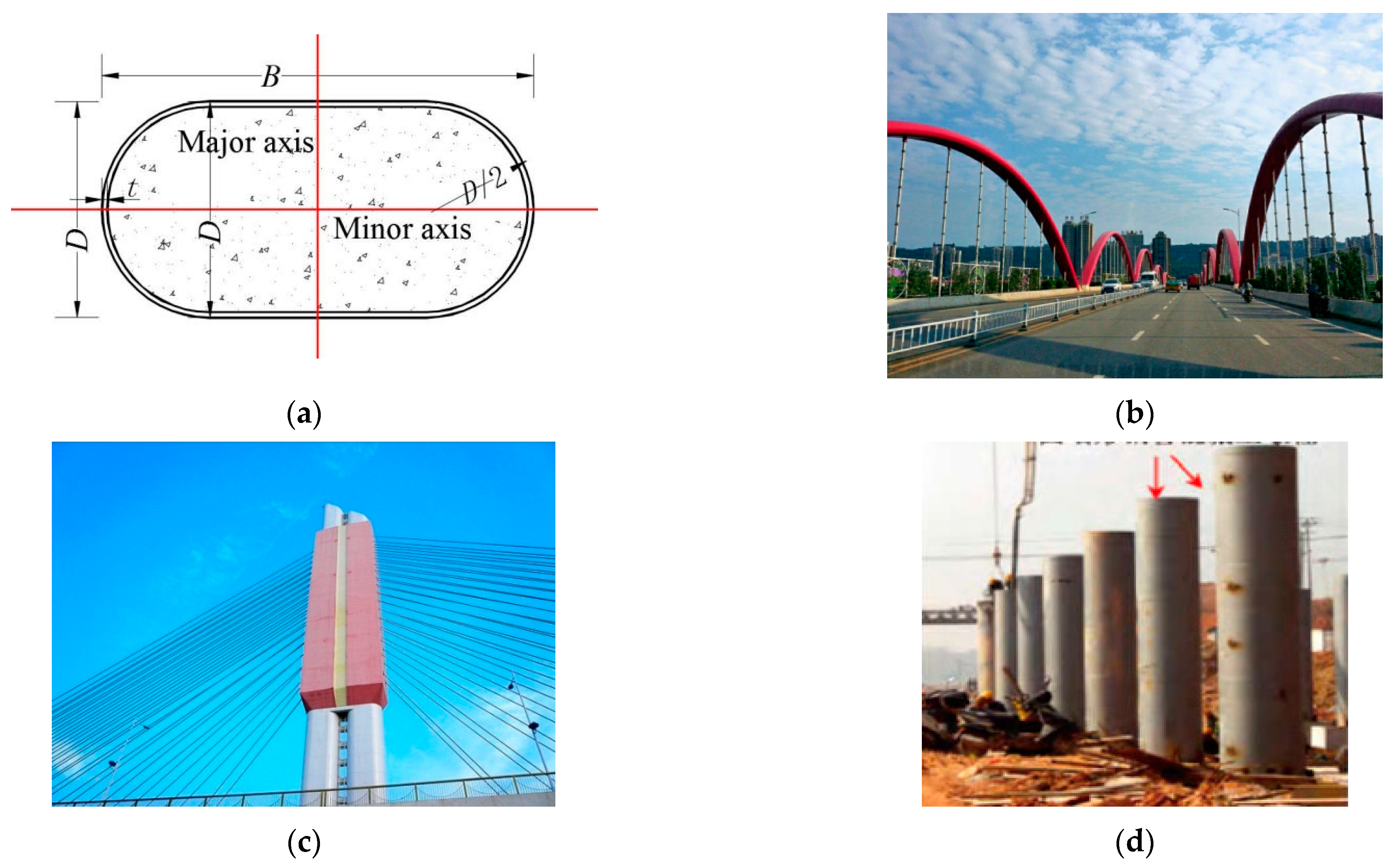
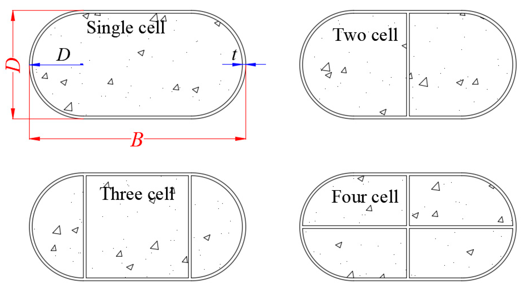
2.1. Test Specimen
2.2. Material Properties
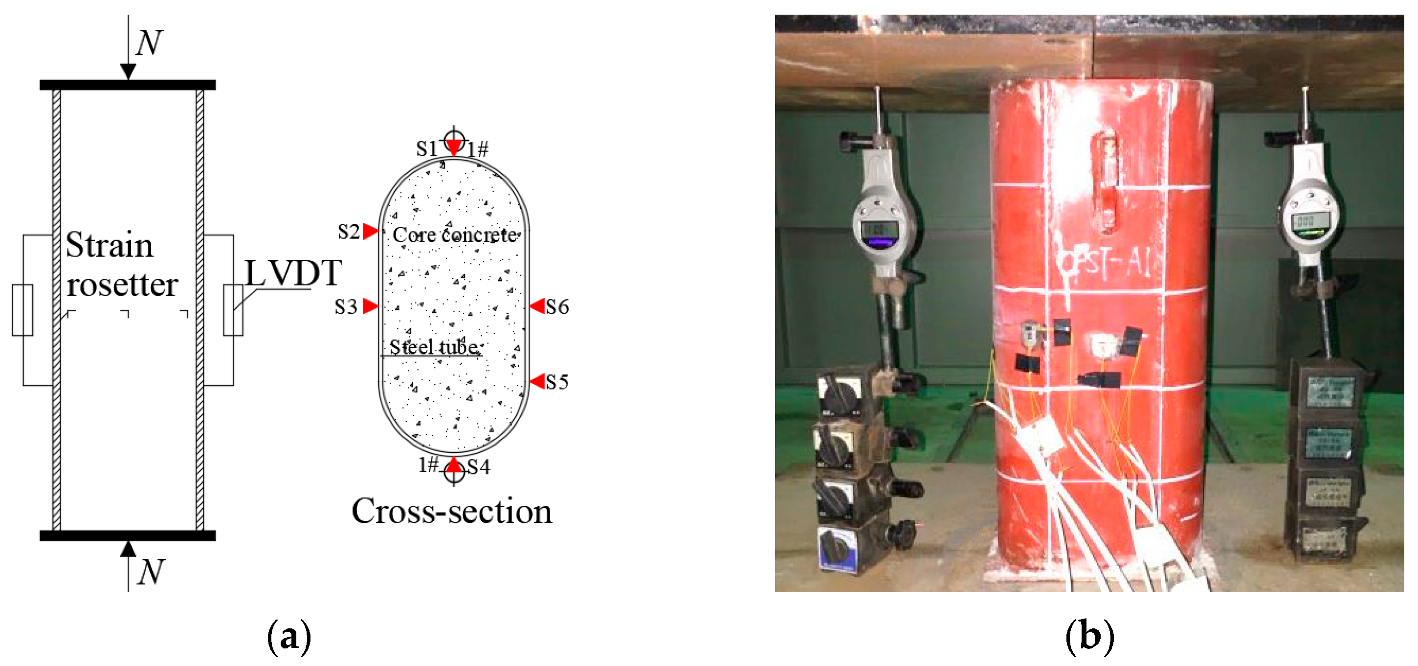
2.3. Experimental Instrumentation
3. Experimental Results Analysis
3.1. Failure Stages
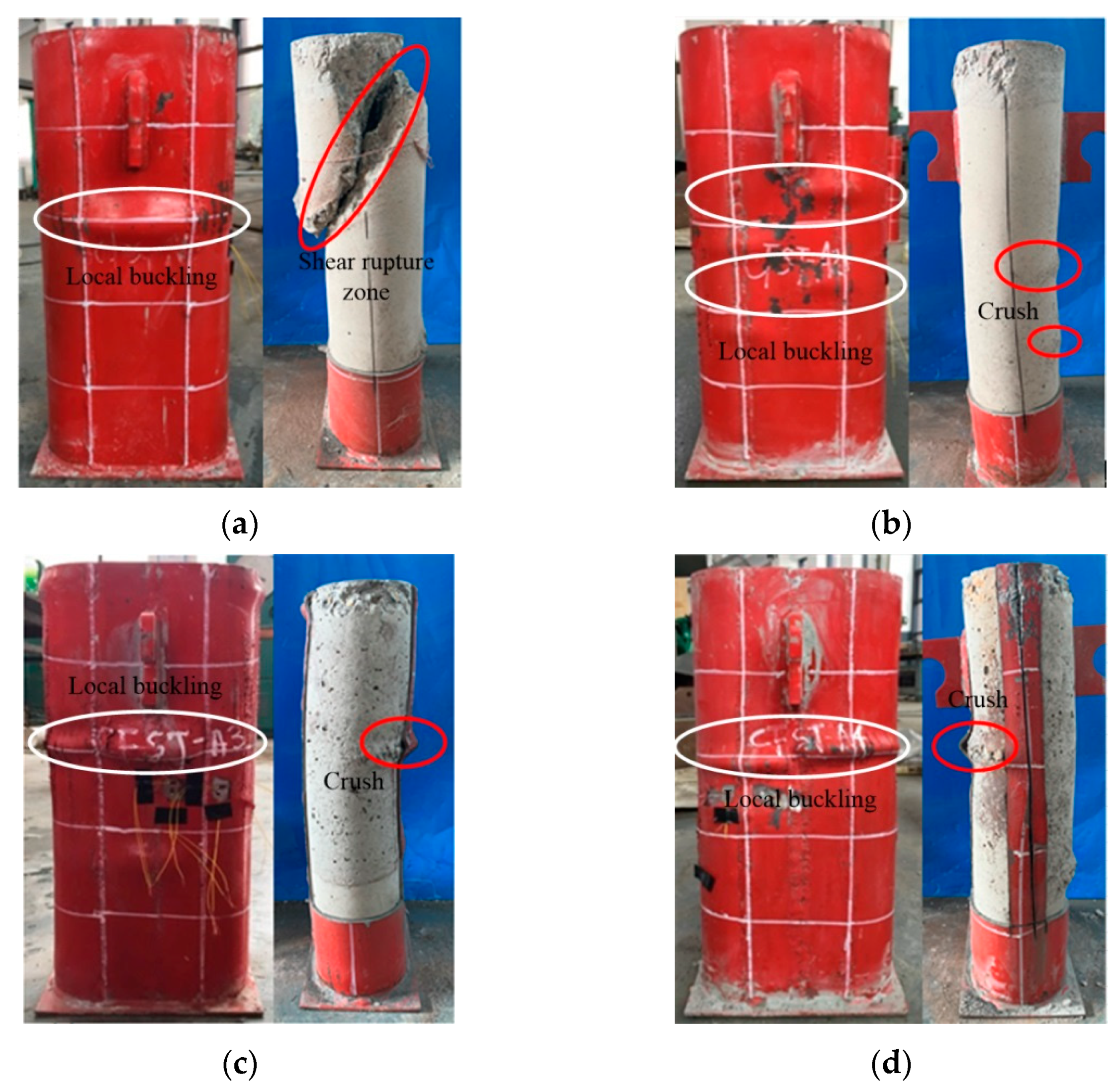
3.2. Damage Modes
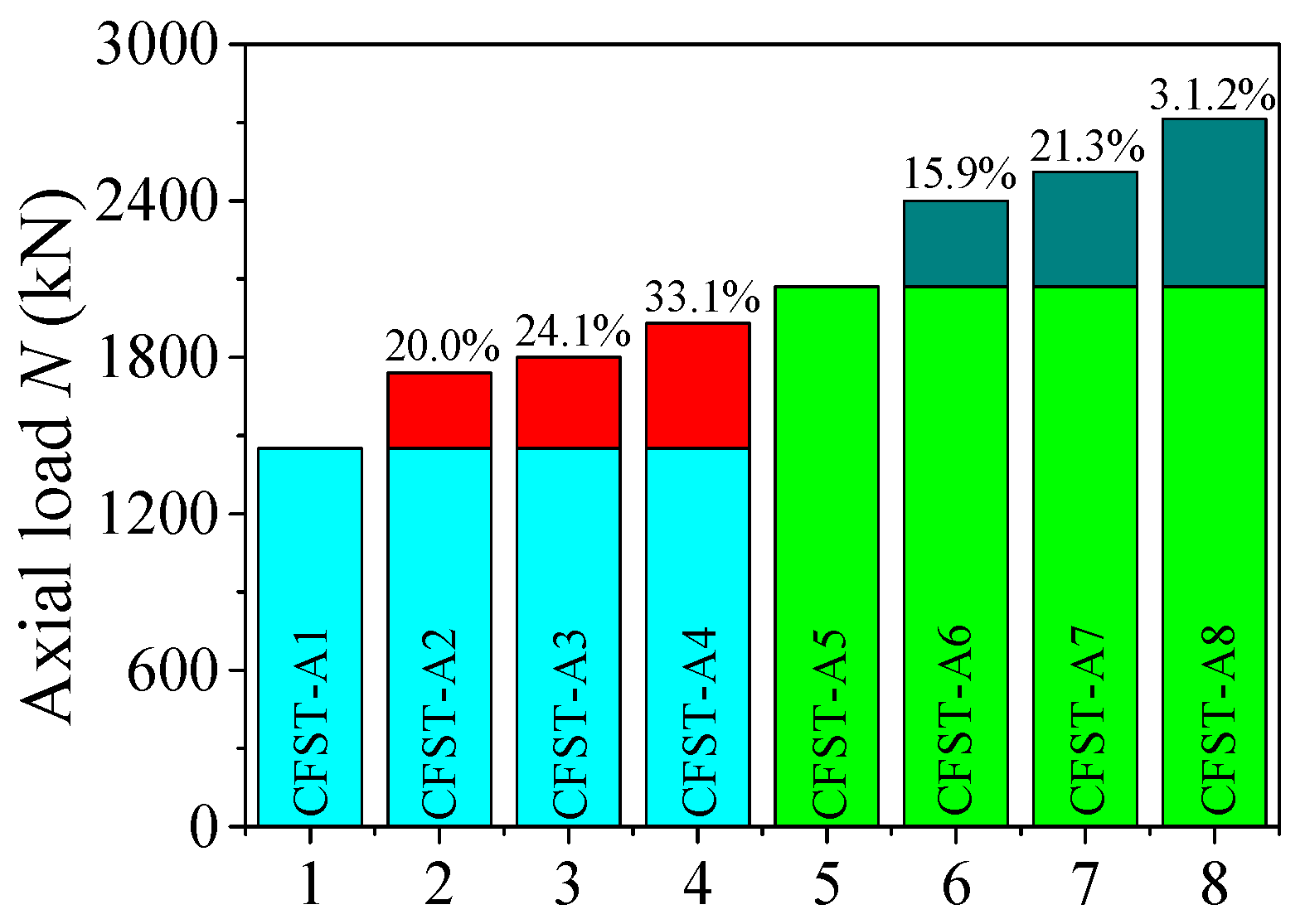
3.3. Ultimate Carrying Capacity
3.4. Ductility
4. FEA
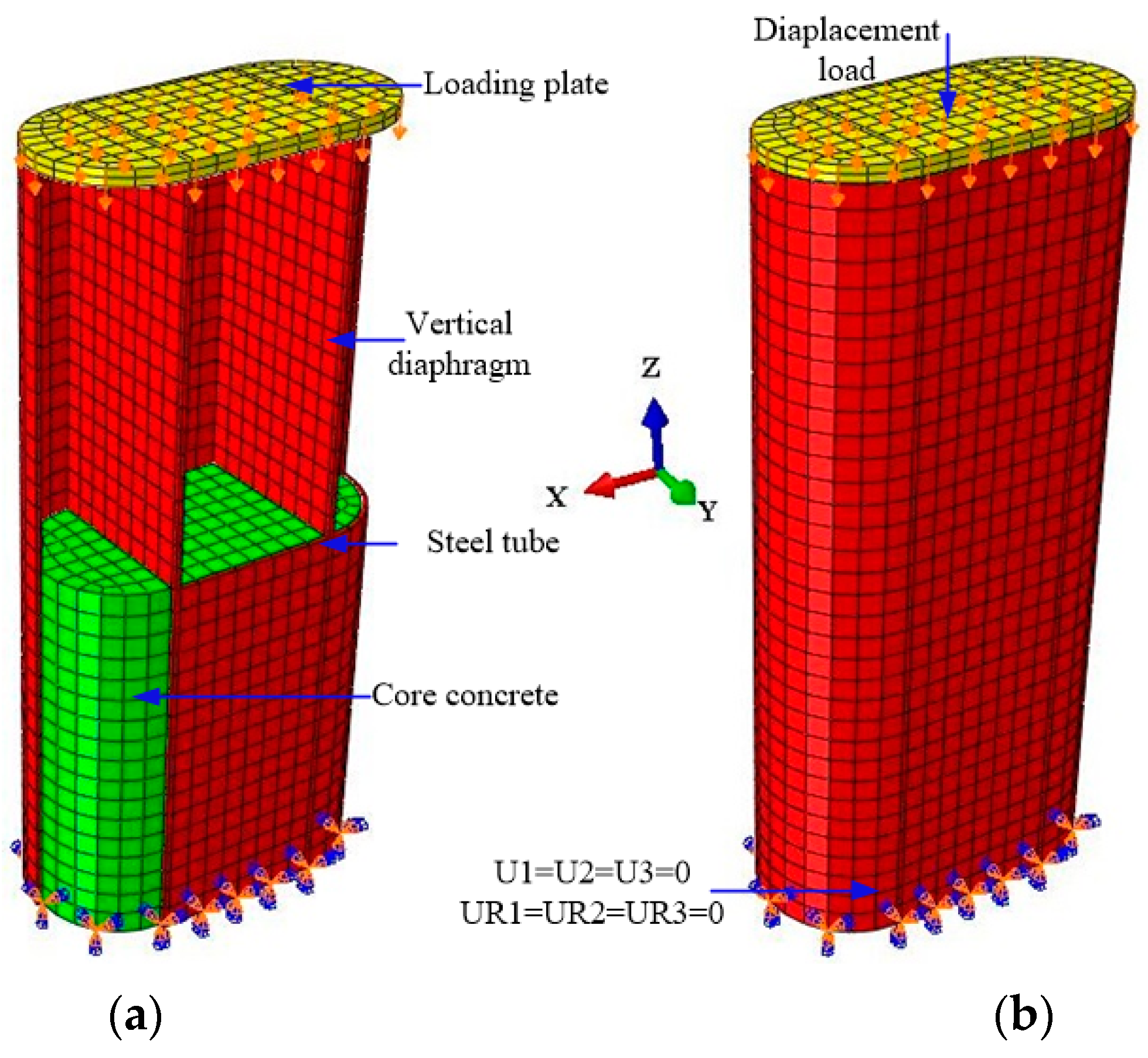
4.1. FE Models
4.2. Material Constitutive Models
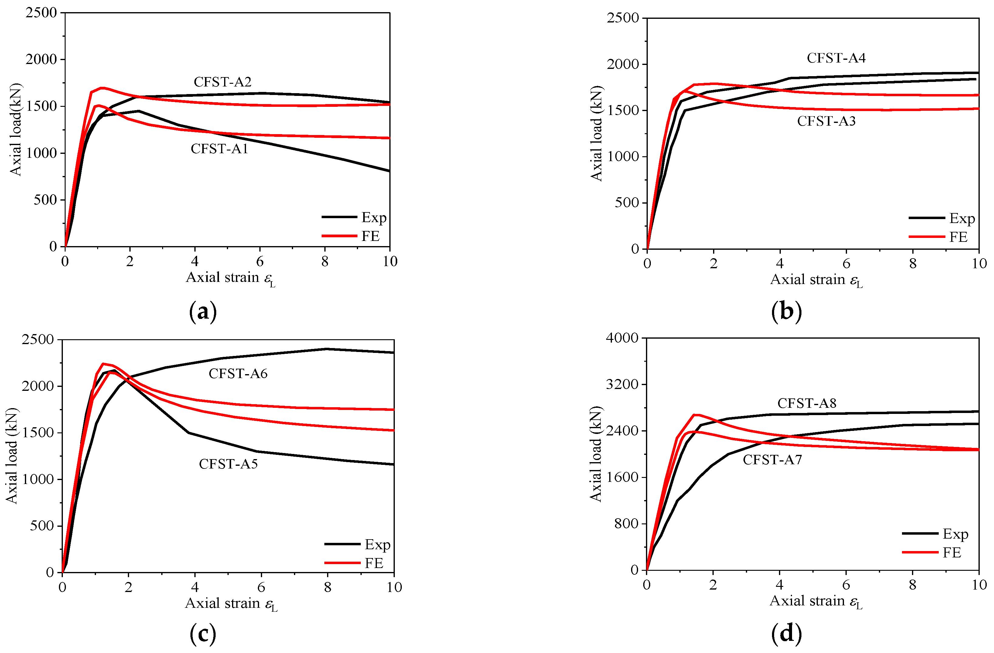
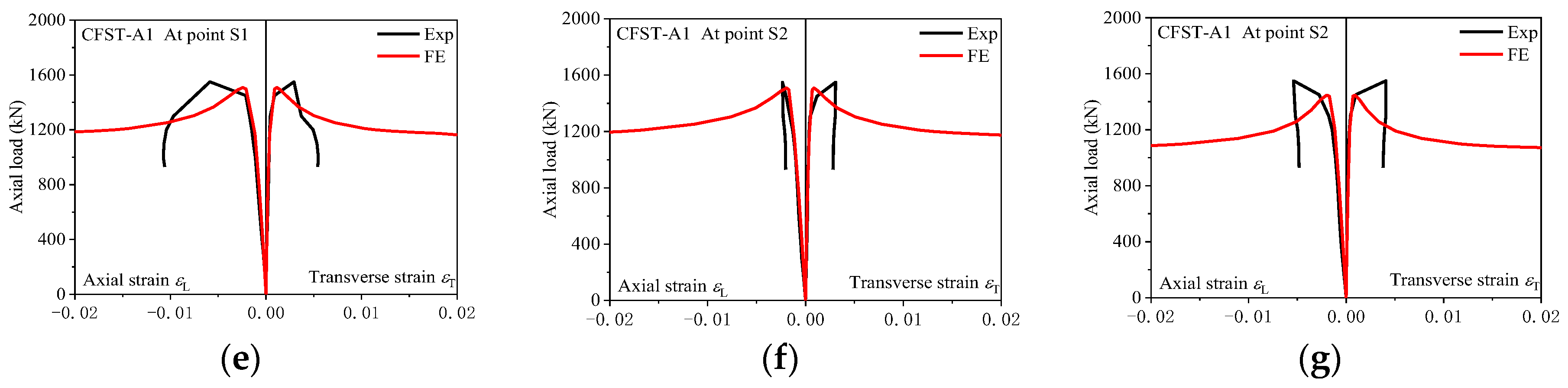
4.3. Experimental Verification
5. Design Approach
5.1. Parametric Study
5.2. Model Simplification
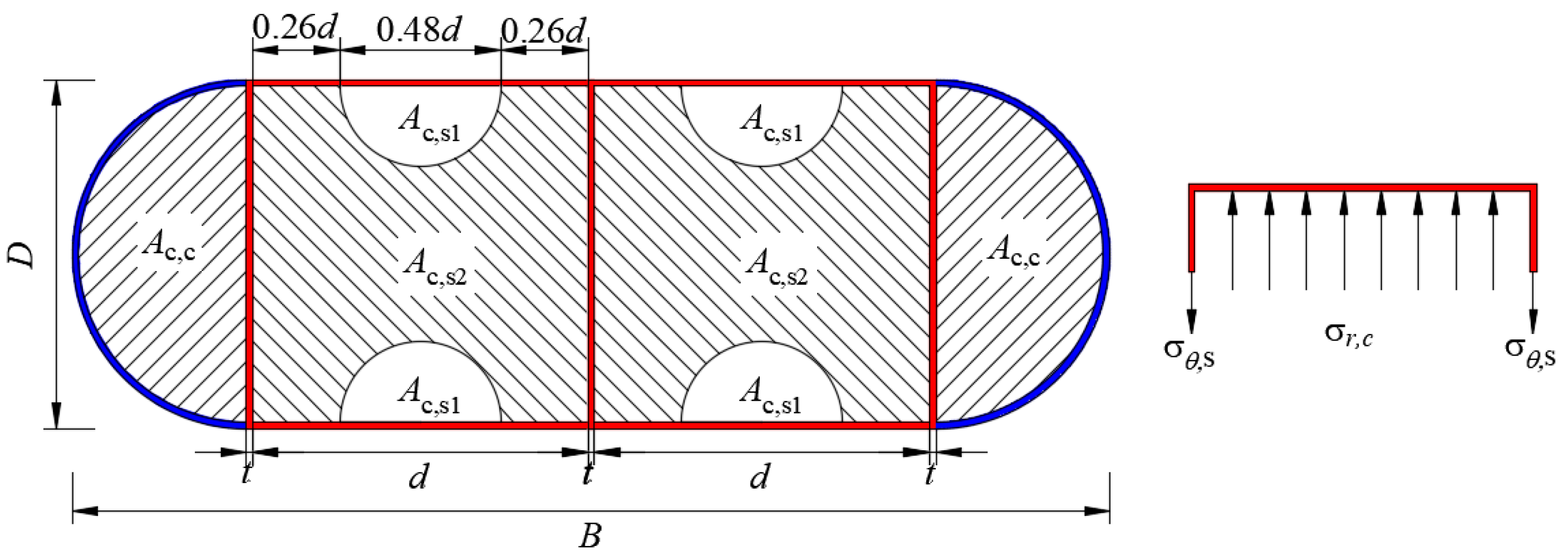
5.3. Formulation
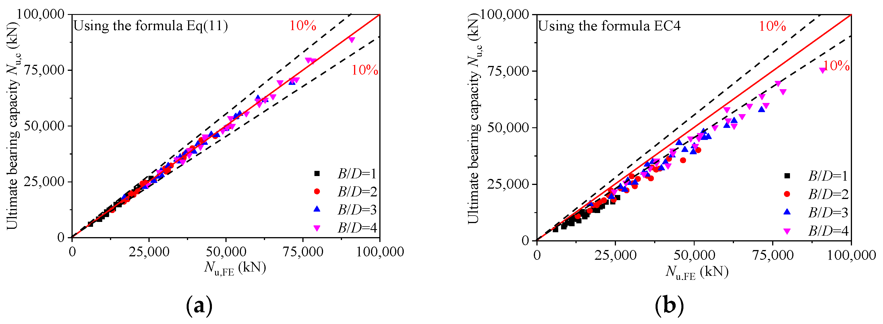
5.4. Formula Validation
6. Conclusions
- (1)
- On the basis of the test results, all the specimens under axial loading are thought to undergo three stages before failing: elastic stage, elastic–plastic stage, and failure stage. Additionally, the vertical diaphragm (chamber number), which can effectively prevent and/or delay the core concrete crushing, essentially changes the failure modes of M-CFRT stub columns. Furthermore, M-CFRT stub columns exhibit greater ductility compared with CFRT stub columns.
- (2)
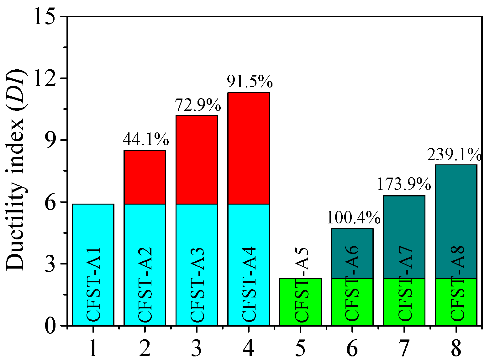
- The ultimate carrying capacity and ductility of M-CFRT stub columns remarkably increase with the increase in the chamber number in the steel tube. That is, the axial behavior of M-CFRT stub columns is improved by the multi-chamber steel tube, namely, the vertical diaphragm.
- (3)
- The observed strong concordance between tested and FE results suggests a favorable agreement. On the basis of these observations, a simplified formula for calculating the ultimate bearing capacity of M-CFRT stub columns is introduced, employing the limit equilibrium method. The predicted results from this formula align well with FE and experimental ones. Consequently, this formula is a reasonable and feasible calculation method for M-CFRT stub columns.
Author Contributions
Funding
Data Availability Statement
Conflicts of Interest
References
- Shen, Q.H.; Wang, J.H.; Wang, W.Q.; Wang, Z.B. Performance and design of eccentrically-loaded concrete-filled round-ended elliptical hollow section stub columns. J. Constr. Steel Res. 2018, 150, 99–114. [Google Scholar] [CrossRef]
- Singh, H.; Tiwary, A.K.; Eldin, S.M.; Ilyas, R.A. Behavior of stiffened concrete-filled steel tube columns infilled with nanomaterial-based concrete subjected to axial compression. J. Mater. Res. Technol. 2023, 24, 9580–9593. [Google Scholar] [CrossRef]
- Ding, F.X.; Fu, L.; Yu, Z.W.; Li, G. Mechanical performances of concrete-filled steel tubular stub columns with round ends under axial loading. Thin-Walled Struct. 2015, 97, 22–34. [Google Scholar]
- Liao, J.; Zeng, J.J.; Quach, W.M.; Zhou, J.K. Axial compressive behavior and model assessment of FRP-confined seawater sea-sand concrete-filled stainless steel tubular stub columns. Compos. Struct. 2023, 311, 116782. [Google Scholar] [CrossRef]
- Liao, J.; Li, Y.L.; Ouyang, Y.; Zeng, J.J. Axial compression tests on elliptical high strength steel tubes filled with self-compacting concrete of different mix proportions. J. Build. Eng. 2021, 40, 102678. [Google Scholar] [CrossRef]
- Al-Nini, A.; Nikbakht, E.; Syamsir, A.; Shafiq, N.; Mohammed, B.S.; Al-Fakih, A.; Al-Nini, W.; Amran, Y.M. Flexural behavior of double-skin steel tube beams filled with fiber-reinforced cementitious composite and strengthened with CFRP sheets. Materials 2020, 13, 3064. [Google Scholar] [CrossRef]
- Xie, J.X.; Lu, Z.A.; Tang, P.; Liu, D. Modal analysis and experimental study on round-ended CFST coupled column cable stayed bridge. In Proceedings of the 2nd International Conference on Mechanic Automation and Control Engineering (MACE), Inner Mongolia, China, 15–17 July 2011; Volume 8, pp. 2302–2304. [Google Scholar]
- Xie, J.X.; Lu, Z.A. Numerical simulation and test study on non-uniform areas of round-ended CFST tubular tower. In Proceedings of the Third International Conference on Information and Computing (ICIC2010), Wuxi, China, 4–6 June 2010; Volume 4, pp. 19–22. [Google Scholar]
- Al-Fakih, A.; Al-Osta, M.A. Finite element analysis of rubberized concrete interlocking masonry under vertical loading. Materials 2022, 15, 2858. [Google Scholar] [CrossRef] [PubMed]
- Gong, F.; Maekawa, K. Multi-scale simulation of freeze-thaw damage to RC column and its restoring force characteristics. Eng. Struct. 2018, 156, 522–536. [Google Scholar] [CrossRef]
- Zhu, X.; Abe, H.; Hayashi, D.; Tanaka, H. Behavioral characteristics of RC beams with non-uniform corrosion along the reinforcement. J. Intell. Constr. 2023, 1, 9180019. [Google Scholar] [CrossRef]
- Li, P.; Wang, H.; Nie, D.; Wang, D.; Wang, C. A method to analyze the long-term durability performance of underground reinforced concrete culvert structures under coupled mechanical and environmental loads. J. Intell. Constr. 2023, 1, 9180011. [Google Scholar] [CrossRef]
- Wan, C.Y.; Zha, X.X. Nonlinear analysis and design of concrete-filled dual steel tubular columns under axial loading. Steel Compos. Struct. 2016, 20, 571–597. [Google Scholar] [CrossRef]
- Zhu, A.Z.; Zhang, X.W.; Zhu, H.P.; Zhu, J.H.; Lu, Y. Experimental study of concrete filled cold-formed steel tubular stub columns. J. Constr. Steel Res. 2017, 134, 17–27. [Google Scholar] [CrossRef]
- Wang, J.F.; Shen, Q.H.; Jiang, H.; Pan, X.B. Analysis and design of elliptical concrete filled thin-walled steel stub columns under axial compression. Int. J. Steel Struct. 2018, 18, 365–380. [Google Scholar] [CrossRef]
- Zhao, Y.G.; Yan, X.F.; Lin, S.Q. Compressive strength of axially loaded circular hollow centrifugal concrete-filled steel tubular short columns. Eng. Struct. 2019, 201, 109828. [Google Scholar] [CrossRef]
- Pi, T.; Chen, Y.; He, K.; Han, S.H.; Wan, J. Study on circular CFST stub columns with double inner square steel tubes. Thin-Walled Struct. 2019, 140, 195–208. [Google Scholar] [CrossRef]
- Zhou, F.; Young, B. Experimental investigation of concrete-filled single-skin and double-skin steel oval hollow section stub columns. Thin-Walled Struct. 2019, 140, 157–167. [Google Scholar] [CrossRef]
- Han, L.H.; Ren, Q.X.; Li, W. Tests on stub stainless steel-concrete-carbon steel double-skin tubular (DST) columns. J. Constr. Steel Res. 2011, 67, 437–452. [Google Scholar] [CrossRef]
- Wang, J.F.; Shen, Q.H. Numerical analysis and design of thin-walled RECFST stub columns under axial compression. Thin-Walled Struct. 2018, 129, 166–182. [Google Scholar] [CrossRef]
- Ding, F.X.; Fu, L.; Liu, X.M.; Liu, J. Mechanical performances of track-shaped rebar stiffened concrete-filled steel tubular (SCFRT) stub columns under axial compression. Thin-Walled Struct. 2016, 99, 168–181. [Google Scholar] [CrossRef]
- GB 50017-2003; Code for Design of Steel Structures. China Planning Press: Beijing, China, 2003.
- Zhang, T.; Ding, F.X.; Wang, L.P.; Liu, X.M.; Jiang, G.S. Behavior of polygonal concrete-filled steel tubular stub columns under axial loading. Steel Compos. Struct. 2018, 28, 573–588. [Google Scholar]
- Smith, M. ABAQUS/Standard User’s Manual, Version 6.9; Dassault Systèmes Simulia Corp.: Providence, RI, USA, 2009. [Google Scholar]
- Ding, F.X.; Ying, X.Y.; Zhou, L.C.; Yu, Z.W. Unified calculation method and its application in determining the uniaxial mechanical properties of concrete. Front Struct. Civ. Eng. 2011, 5, 381–393. [Google Scholar] [CrossRef]
- EN 1994-1-1:2004; Design of Composite Steel and Concrete Structures Part1-1: General Rules-Structural Rules for Buildings. European Committee for Standardization: Brussels, Belgium, 2004.


| No. | Specimen ID | B × D × t × H/mm | B/D | Chamber | fs | fcu | ρs | Nu,e/kN |
|---|---|---|---|---|---|---|---|---|
| 1 | CFST-A1 | 228 × 114 × 4 × 500 | 2 | 1 | 334 | 37 | 10.1 | 1420 |
| 2 | CFST-A2 | 228 × 114 × 4 × 500 | 2 | 2 | 334 | 37 | 12.1 | 1740 |
| 3 | CFST-A3 | 228 × 114 × 4 × 500 | 2 | 3 | 334 | 37 | 14.0 | 1800 |
| 4 | CFST-A4 | 228 × 114 × 4 × 500 | 2 | 4 | 334 | 37 | 16.0 | 1930 |
| 5 | CFST- A5 | 342 × 114 × 4 × 500 | 3 | 1 | 334 | 37 | 9.0 | 1830 |
| 6 | CFST- A6 | 342 × 114 × 4 × 500 | 3 | 2 | 334 | 37 | 10.3 | 2400 |
| 7 | CFST- A7 | 342 × 114 × 4 × 500 | 3 | 3 | 334 | 37 | 11.5 | 2510 |
| 8 | CFST- A8 | 342 × 114 × 4 × 500 | 3 | 4 | 334 | 37 | 14.0 | 2715 |
| D/mm | B/mm | B/D | ρs | Cell Number | L/mm |
|---|---|---|---|---|---|
| 1200 | 2400 | 2 | 0.02~0.08 | 1~4 | 5500 |
| 3600 | 3 | 5500 | |||
| 4800 | 4 | 7000 |
Disclaimer/Publisher’s Note: The statements, opinions and data contained in all publications are solely those of the individual author(s) and contributor(s) and not of MDPI and/or the editor(s). MDPI and/or the editor(s) disclaim responsibility for any injury to people or property resulting from any ideas, methods, instructions or products referred to in the content. |
© 2024 by the authors. Licensee MDPI, Basel, Switzerland. This article is an open access article distributed under the terms and conditions of the Creative Commons Attribution (CC BY) license (https://creativecommons.org/licenses/by/4.0/).
Share and Cite
Liu, J.; Zhang, T.; Pan, Z.; Ma, F. Behavior of Concrete-Filled Steel Tube Columns with Multiple Chambers and Round-Ended Cross-Sections under Axial Loading. Buildings 2024, 14, 846. https://doi.org/10.3390/buildings14030846
Liu J, Zhang T, Pan Z, Ma F. Behavior of Concrete-Filled Steel Tube Columns with Multiple Chambers and Round-Ended Cross-Sections under Axial Loading. Buildings. 2024; 14(3):846. https://doi.org/10.3390/buildings14030846
Chicago/Turabian StyleLiu, Jing, Tao Zhang, Zhicheng Pan, and Fanjun Ma. 2024. "Behavior of Concrete-Filled Steel Tube Columns with Multiple Chambers and Round-Ended Cross-Sections under Axial Loading" Buildings 14, no. 3: 846. https://doi.org/10.3390/buildings14030846