1. Introduction
With the development of society and the progress of urbanization, the land for urban construction is becoming increasingly scarce. Due to the scarcity of land resources, urban construction is gradually shifting to high and deep ground, which makes the excavation depth and area of the foundation pit project larger and larger, the environment and geological conditions around the foundation pit more complex, and the requirements for deformation limitation more demanding [
1,
2,
3].
In order to adapt to various complex engineering conditions, the pile support structure of the deep foundation pit has been developed from single-row pile to double-row pile, but with the further deepening of the foundation pit and the more complex engineering geological conditions, the double-row pile structure could not meet the requirements of some projects, and has to be used in combination with internal support and anchors, which has lost the advantages of the convenient construction. To solve this problem, a new type of foundation pit support structure, the three-row pile, has emerged, which has greater lateral bending stiffness, higher overturning resistance, and can better limit the deformation of the support structure. The three-row pile structure has a better development prospect, and has attracted the attention of more researchers.
Currently, the research on the design theory and calculation model of the double-row pile support structure has matured significantly and yielded substantial results [
4,
5,
6,
7,
8,
9,
10,
11,
12]. Nevertheless, the research on the three-row pile support structure remains insufficiently deep and systematic. For instance, Ma et al. [
13] proposed a step-type support structure that combined three-row piles and single-row piles. The structure offers various benefits such as flexible arrangement, high support stiffness, no requirement of an internal support structure, and a reduction in the construction period. Xin et al. [
14] conducted a model test to analyze the damage morphology, deformation, and bending moment of three-row piles. Similarly, Tian et al. [
15] studied the deformation and internal force of three rows of piles on the high and deep bank slope of a city waterway. The impact of variables, including row spacing, pile stiffness, and connecting beam stiffness, were investigated. Subsequently, appropriate design parameters for a three-row pile support structure were established, including row spacing, soil reinforcement location, and connecting beam thickness. Qian et al. [
16] conducted force calculations using a pile-spring model for a three-row pile situated on a river slope. The resultant design of the three-row pile was obtained. Cao [
17] proposed the calculation method for analyzing the overturning stability and mechanical characteristics of three-row piles. The effects of variations in sensitivity parameters on the structure were also analyzed. Wei [
18] computed the stress and displacement fields of the pile structure when considering pile–soil interaction. Further, the calculation model of three-row piles was refined. Zhang [
19] established a theoretical calculation model for a three-row pile by simulating an actual deep foundation pit project. This resulted in the derivation of the influence law of various factors on the deformation and internal force of three-row piles.
This study shows a clear absence of a standardized foundation and established calculation theory for the design and calculation of three-row piles. To address the research gap in this field, the present research systematically demonstrates the design process and calculation method of an innovative three-row pile support system. Additionally, this paper firstly proposes the removal steps and cooperative construction technology with basement for high-rise tower structures based on the Xinghe Yabao deep foundation pit project in Shenzhen, China. The finite element software is used to analyze the force and deformation characteristics of the three-row pile support system, as well as the influence of the prestressing anchor cable direction on its effectiveness. The findings could offer a theoretical framework and scientific underpinning for devising and building a three-row pile support structure within an extremely deep foundation pit project.
2. Project Overview
The Xinghe Yabao Project is situated in Bantian Street, Longgang District, Shenzhen City, and encompasses a site area of 38,800 m
2 with a total construction area of 354,400 m
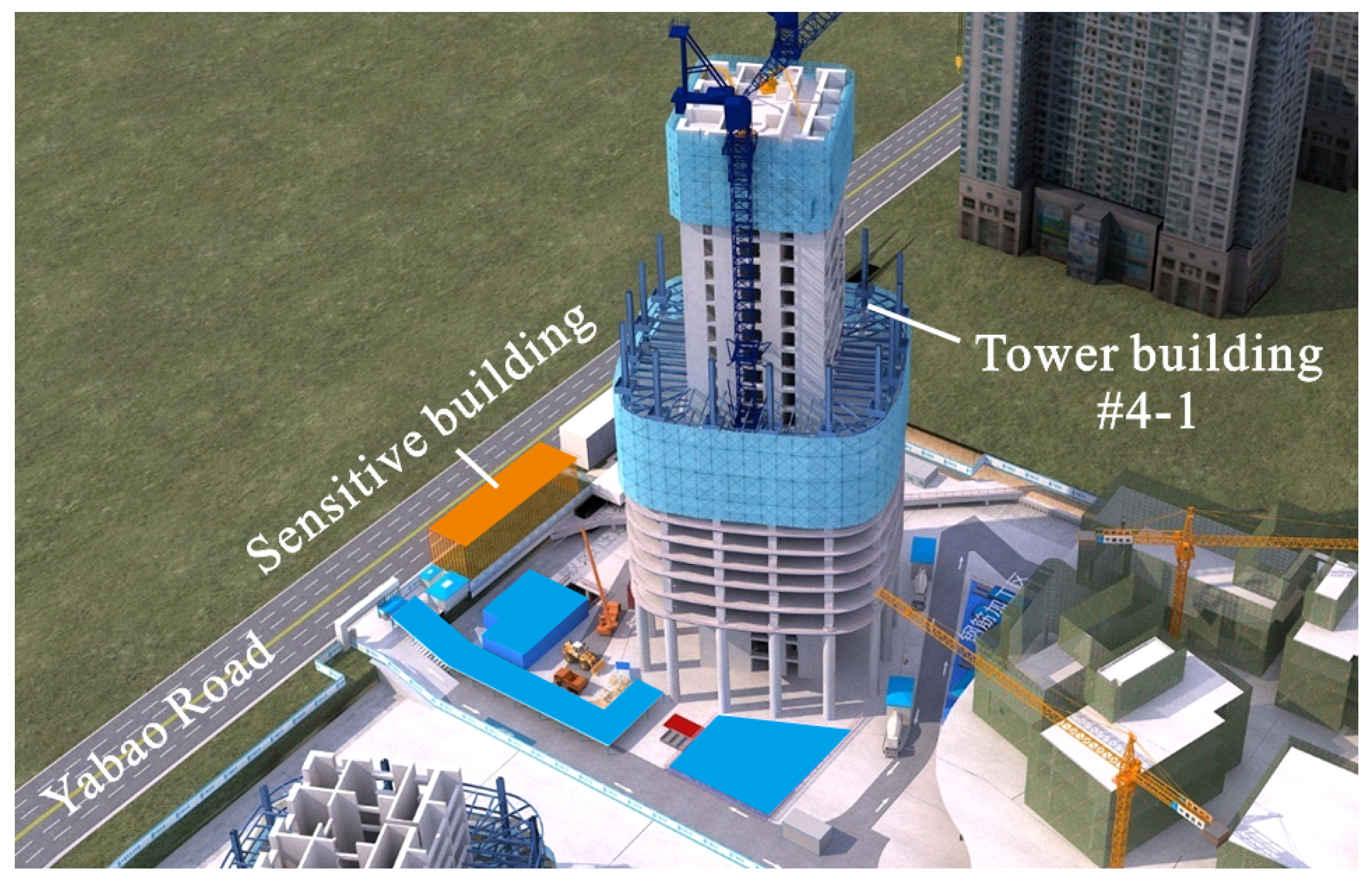
2. The project includes four buildings with five basement levels. Notably, building #4-1 is a 74-storey ultra-high-rise tower building, with a structural height of 338.1 m and a building height of 356 m (see
Figure 1). Its structural design employs a frame–core–cylinder structure with reinforcement layers. The pit on the north side of the tower building has a depth of approximately 29 m, and the fill layer measures about 15–22 m in thickness. Hilly terrain dominates the east and west sides of the site, with elevations ranging from 102.86 m to 120.02 m. Overall, the site has significant undulations. Based on the drilling, the site’s strata comprise an artificial fill layer, a quaternary alluvial layer, a quaternary residual layer, and coarse-grained granite from the third stage of Yanshan Mountain.
The north side of the ultra-high-rise tower building is adjacent to the municipal road, and the foundation pit’s outer edge is close to the building’s red line. The original foundation pit support design in this area consists of double-row piles. However, due to the presence of a sensitive building on the northern side of the foundation pit, the prestressing anchor cable is prohibited from entering below it. To prevent the prestressing anchors from encroaching on the sensitive buildings, they were moved 9.2 m away from the edge of the pit and towards the pit’s interior. Consequently, the pit support system and basement construction method in the affected area required significant design adjustments.
3. Design and Analysis of Three-Row Pile Support System
3.1. Design Scheme of Three-Row Pile Support System
Due to the nearby sensitive building, a stepped three-row pile system was implemented on the north side of the pit in order to prevent the intrusion of prestressing anchors into the foundation.
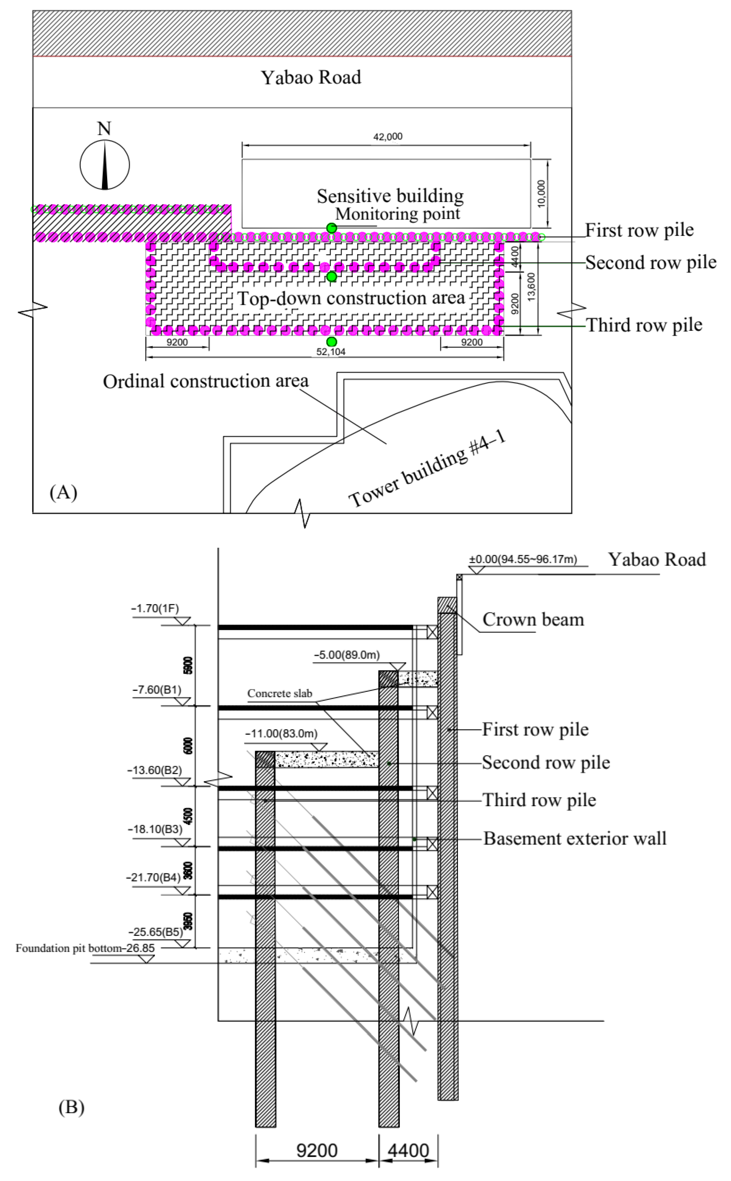
A three-row pile structure is arranged in a backward stepped distribution, from outer to inner areas. The first row of piles features a secant pile wall with a diameter of 1.4 m and spacing of 1.8 m, with the end of the pile anchored to the moderately weathered rock at a depth of at least 0.5 m. The second row consists of reinforced concrete piles with a diameter of 1.4 m and spacing of 2.2 m, anchored into the moderately weathered rock at a depth of at least 5.0 m. The first and second rows of piles are connected by a 1.2 m thick reinforced structure, with a vertical spacing of 5.0 m and horizontal spacing of 4.4 m. The third row consists of reinforced concrete piles, with a diameter of 1.4 m and spacing of 2.2 m. The pile ends are anchored into moderately weathered rock no less than 5.0 m. The vertical spacing between the second and third row of piles measures 6.0 m while the horizontal spacing is 9.2 m. The two rows of piles are joined by a slab made of reinforced concrete with a thickness of 1.2 m. The third row of piles is equipped with five prestressing anchor cables, which are anchored within the range of the first and the second row of piles. The second and third rows of piles are situated in the basement space of the main building.
Figure 2 presents the plan and section layout of the three-row pile structure.
3.2. Calculation Assumptions and Analysis of Three-Row Pile Support System
3.2.1. Computational Assumptions and Model
The design of a three-row pile lacks specification and theoretical guidance. To improve this, we referred to the planar rigid frame structural model of the double-row pile structure in the specification of [
20].
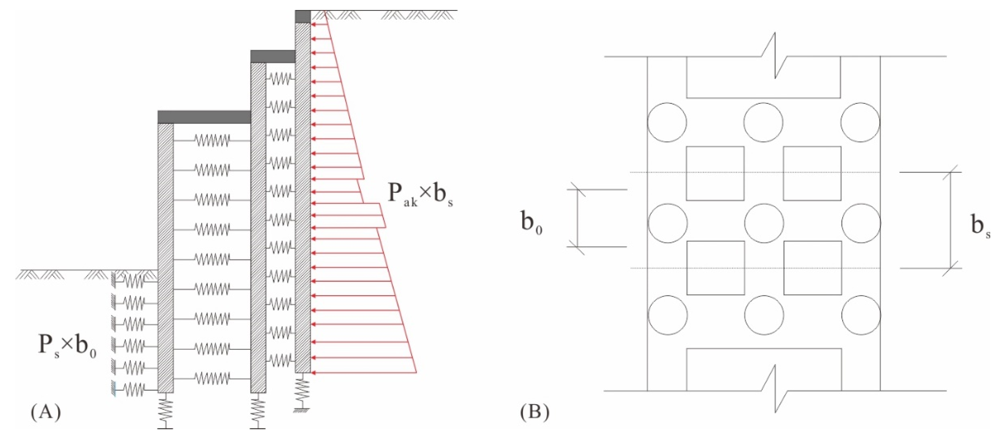
Figure 3 shows the calculation model of the three-row pile supporting structure. For the simplified model, the following assumptions were made.
(1) A third row of support piles is incorporated into the previous double-row pile model, resulting in a three-row pile model. However, the elastic resistance method is still used to calculate the passive soil pressure in front of the front-row piles, while Rankine active soil pressure is applied after the back-row piles. The horizontal soil spring analysis is used to assess the soil between piles, which collaborates with the three-row pile step-type space structure as a rigid body to jointly resist external forces.
(2) The piles within the support system, comprising three rows, are linked by reinforced concrete slabs. The connection at the crown beam is hypothesized as being a bonded connection, while the connection at the planted reinforcement is assumed to be a pinned one.
(3) The innermost pile cannot reach a completely passive state due to control requirements for the displacement of the support system. As a result, it is still in the elastic resistance stage. Therefore, the active soil pressure is taken as the horizontal load applied to the outermost pile, and the displacements and internal forces of the innermost pile are calculated by the elastic foundation beam method. The horizontal support of the pile by the soil in the passive zone is modeled by springs.
(4) The range of lengths for prestressing anchor cables falls within the bounds of the three-row pile stepped space structure. During external stability analysis, the anchor cables function as internal forces and therefore do not factor into force calculations.
3.2.2. Stability Analysis
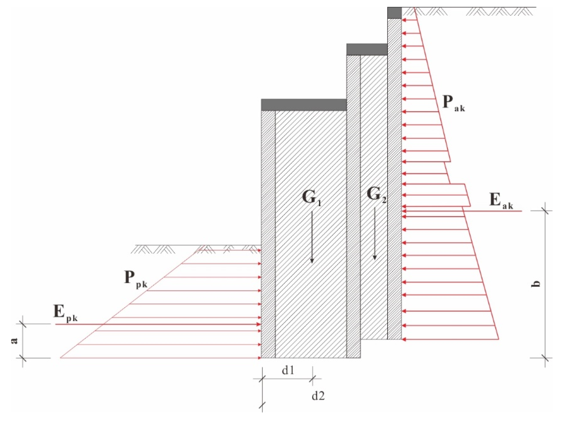
The three-row piles support system generates a sequential spatial formation, with the interstitial soil and support structure jointly opposing external soil pressure. Antioverturning and antisliding stability was determined by the following calculation, and the schematic diagram of three-row piles for stability calculation is shown in
Figure 4. The result of stability calculation of the three-row piles indicates that the three-row piles support system proposed in this paper is safe (see
Table 1).
3.2.3. Finite Element Analysis of Three-Row Pile Support System
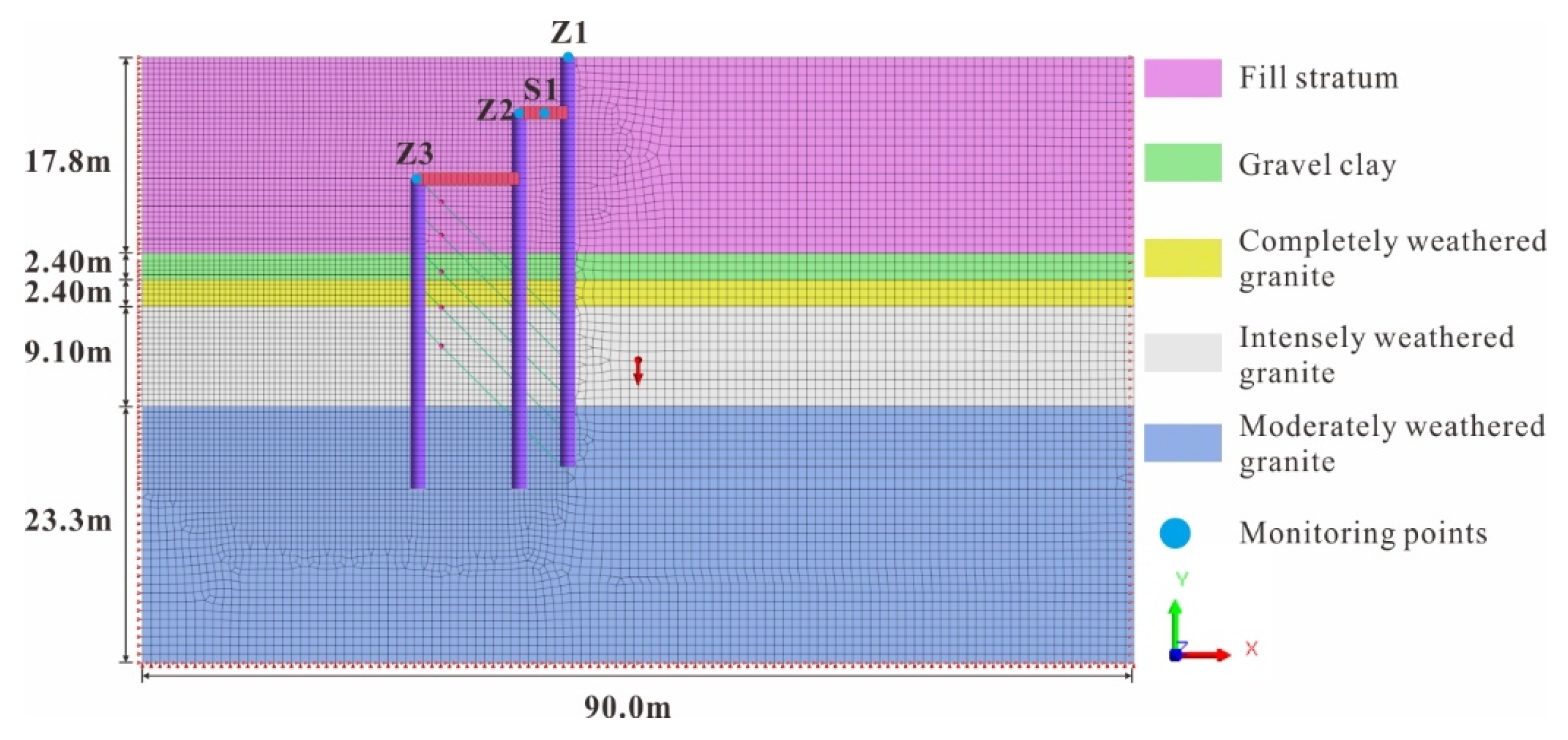
To examine the force and deformation of the support structure consisting of three-row piles, a two-dimensional finite element model was established by the Midas GTS/NX, as illustrated in
Figure 5. The modified Moore Cullen model was chosen as the primary model for the stratum of the foundation pit in this project due to its proficiency in accounting for the hardening characteristics of the geotechnical body and the excavation unloading rebound issue [
22]. The use of this model aided in the analysis of complex geotechnical situations. Based on the geotechnical investigation report and previous research experience [
22], the physical and mechanical parameters of the entire stratum were summarized and are presented in
Table 2. To model the three-row piles and concrete slabs, one-dimensional beam cells were utilized, with a two-dimensional grid cell system used for the soil layer, using a grid size of 0.5~0.8 m, resulting in a total of 12,065 grid cells.
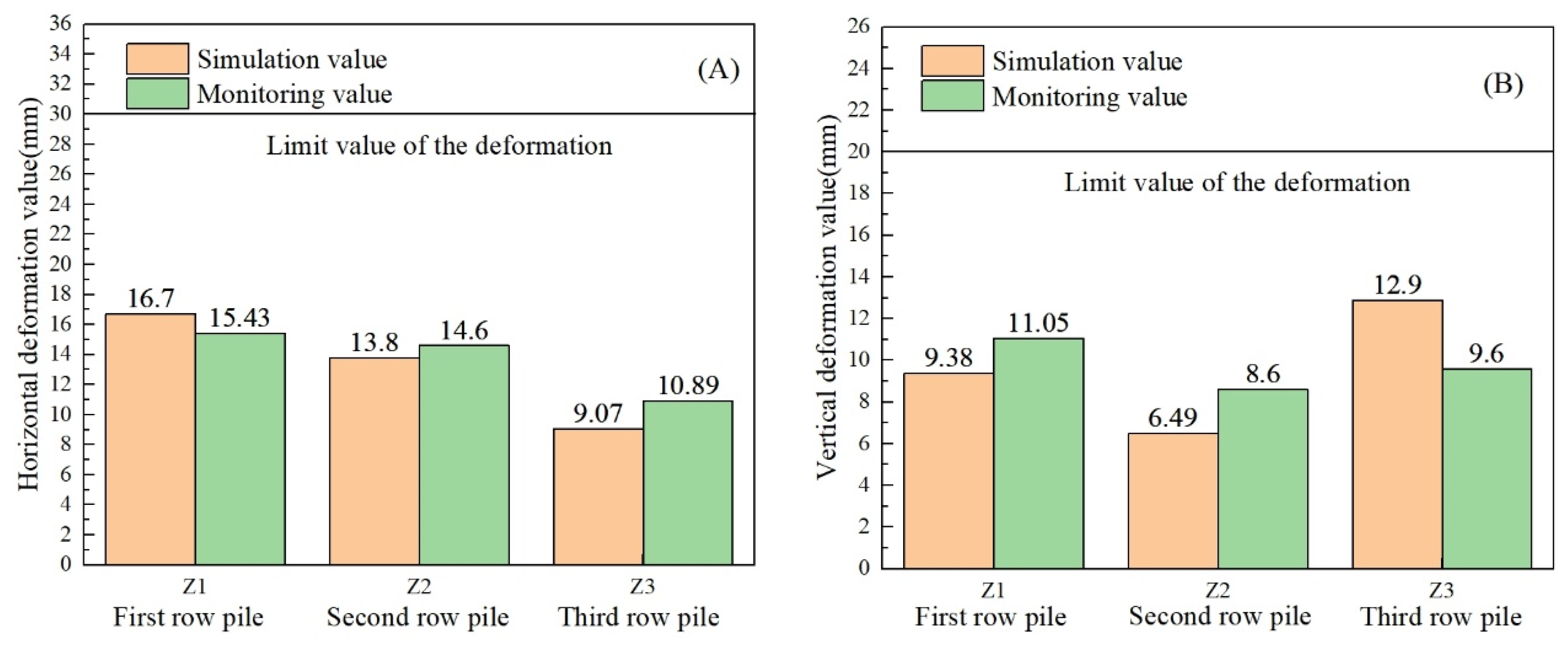
After the excavation to the pit bottom elevation, the results from the finite element simulation showed that both the maximum vertical and horizontal displacements conform to the monitoring results and satisfy the deformation limit value, as shown in
Figure 6. Thus, the numerical model is reliable, and the support system of the three-row pile is safe. The horizontal displacement of the piles revealed that the first row pile experienced the greatest deformation of 16.7 mm, followed by the second pile, and the third pile suffered the least. Moreover, the vertical displacement showed that the third row pile experienced the greatest deformation of 12.9 mm, followed by the first pile, and the second pile had the least deformation. Furthermore, the maximum simulated horizontal displacement (S1) of the soil between the first and second rows of the piles was 13.1 mm and the maximum monitoring value was found to be 15.93 mm, which was well within the deformation limit value of 45 mm.
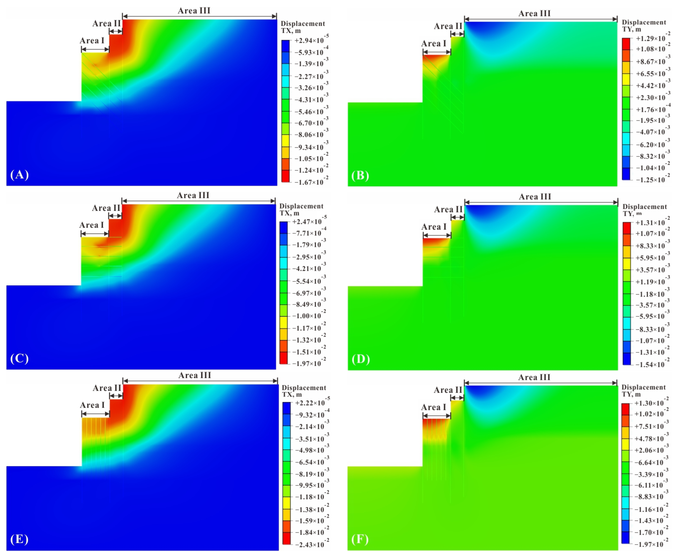
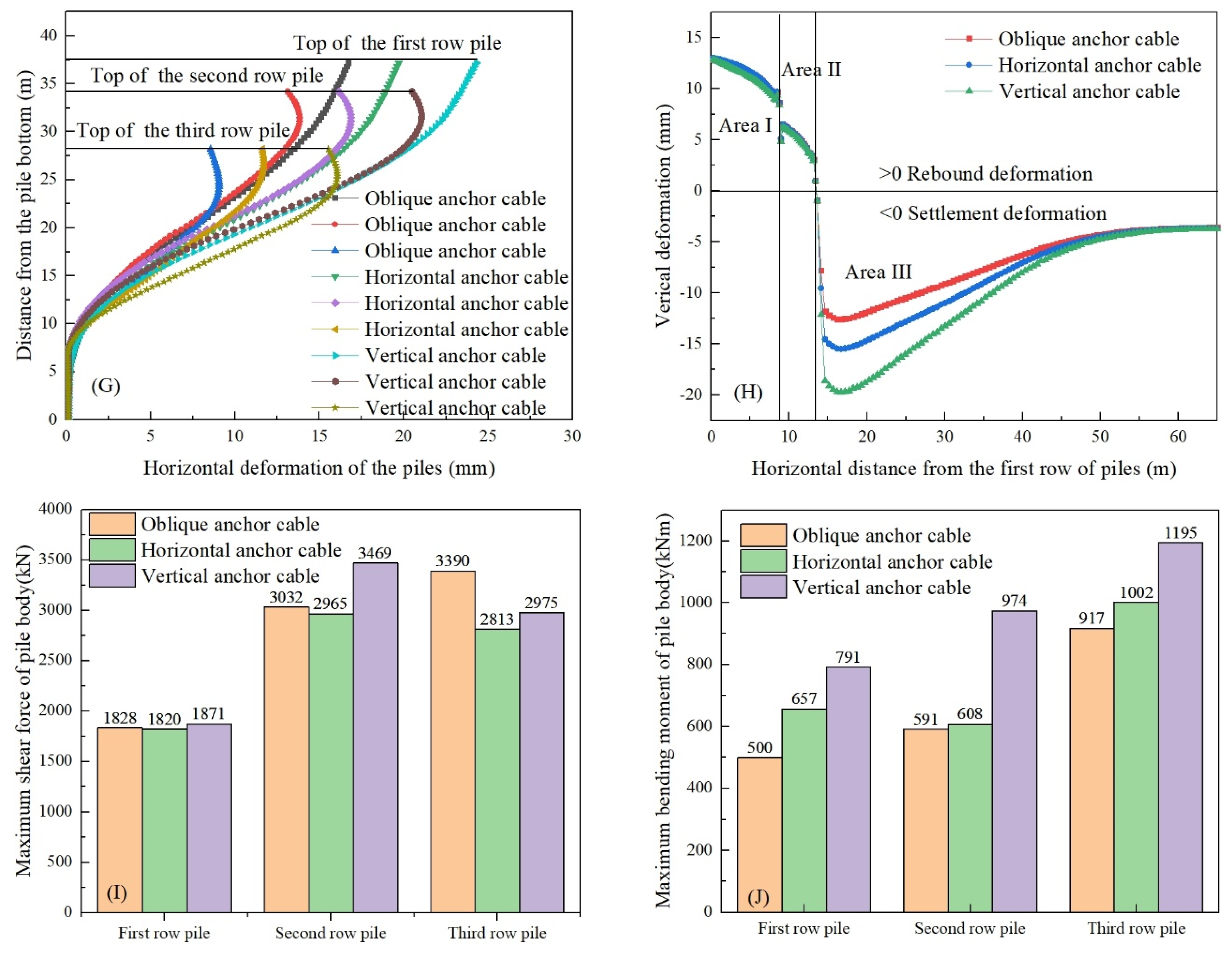
In order to further investigate the influence of the direction of prestressing anchor cables on the supporting effect of the three-row piles, simulations were carried out on the prestressing anchor cables under the three orientations of oblique, horizontal, and vertical. The simulation results showed that the oblique anchor cable had the best support effect and caused the least deformation to the pile body and surrounding layers, followed by the horizontal anchor cable, and the vertical anchor cable produced the largest deformation, so the oblique anchor cable should be preferred in the construction (see
Figure 7A–F). By monitoring the vertical deformation of the soil body in three areas of I, II, and III in
Figure 7B, it was found that the soil body in areas I and II was mainly deformed by rebound, and the amount of rebound of the stratum was minimized under the action of vertical anchors because of their restraining effect on the rebound of the stratum to a certain extent. Area III was the influence area outside the pit, which was mainly affected by horizontal deformation and settlement deformation occurred, and the settlement caused by oblique anchors was minimized (see
Figure 7G,H). In addition, the direction of anchor cable application also affected the internal force of the pile body; when the anchor cable was applied along the vertical direction, the shear force and bending moment generated in the pile body were the largest. When the anchor cable was applied along the oblique direction, the shear force and bending moment generated in the pile body of the third-row piles were the largest, followed by the second-row piles, and the first-row piles were the smallest (see
Figure 7I,J).
4. Removal and Cooperative Construction Technology of the Three-Row Piles and Basement in Top-Down Area
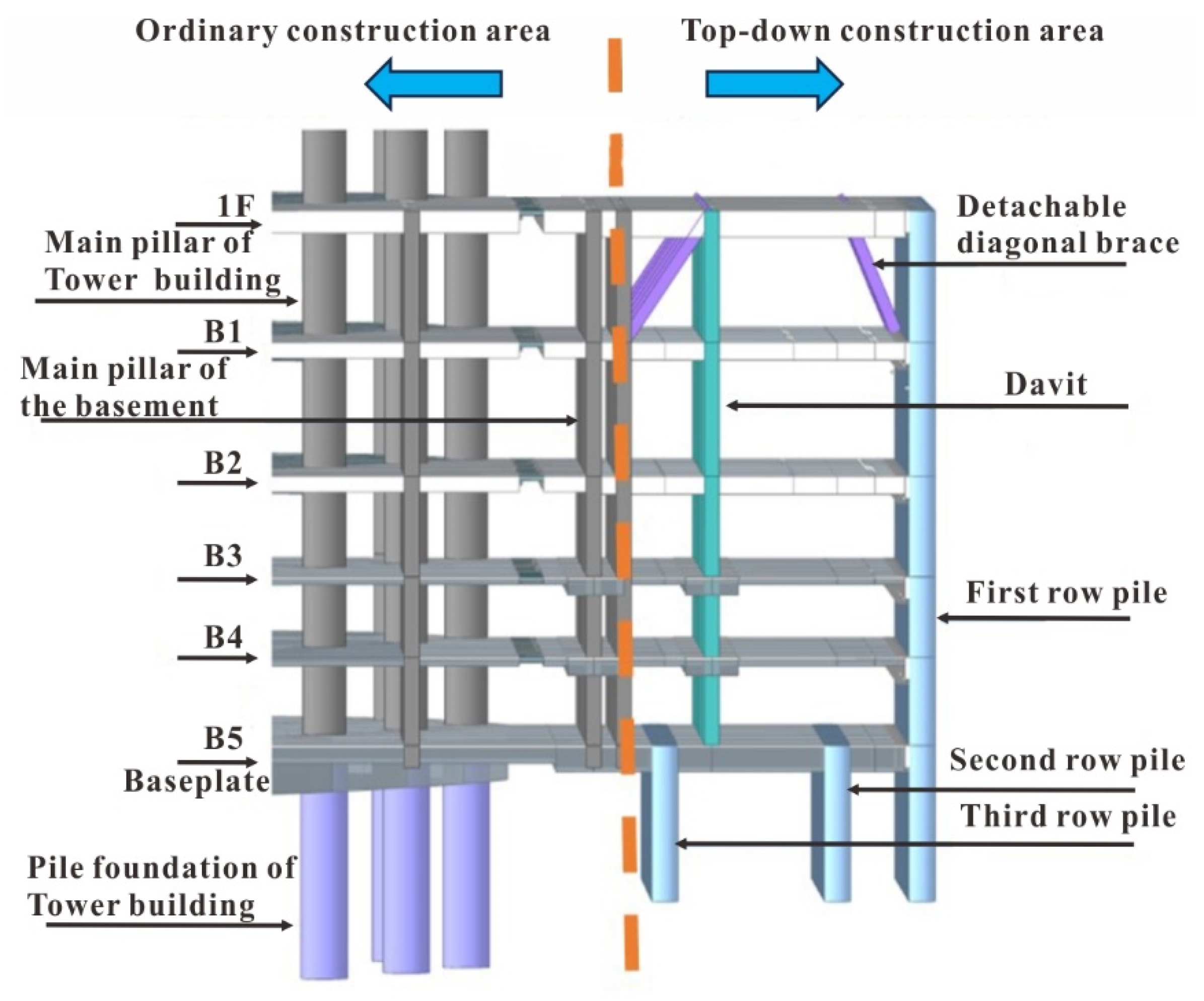
As the three-row pile support system encroached on the tower building basement construction area, the basement outside the three-row pile confinement area was constructed using the ordinary construction method. The basement in the three-row pile confinement area was constructed using the top-down method, so that the soil pressure on the north side of the foundation pit could be transferred to the tower building through the basement floor slab layer, forming a supporting structure (see
Figure 8).
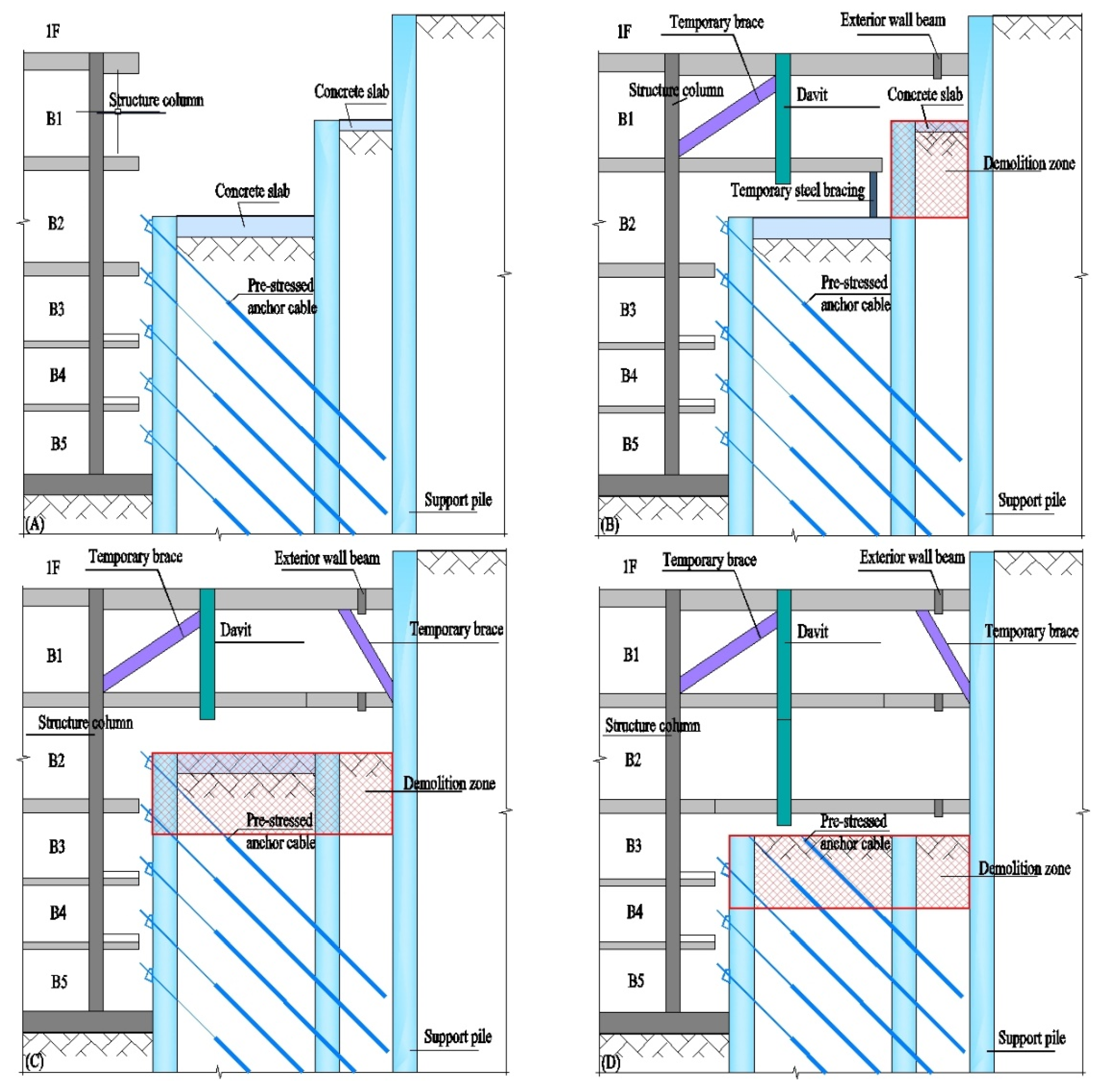
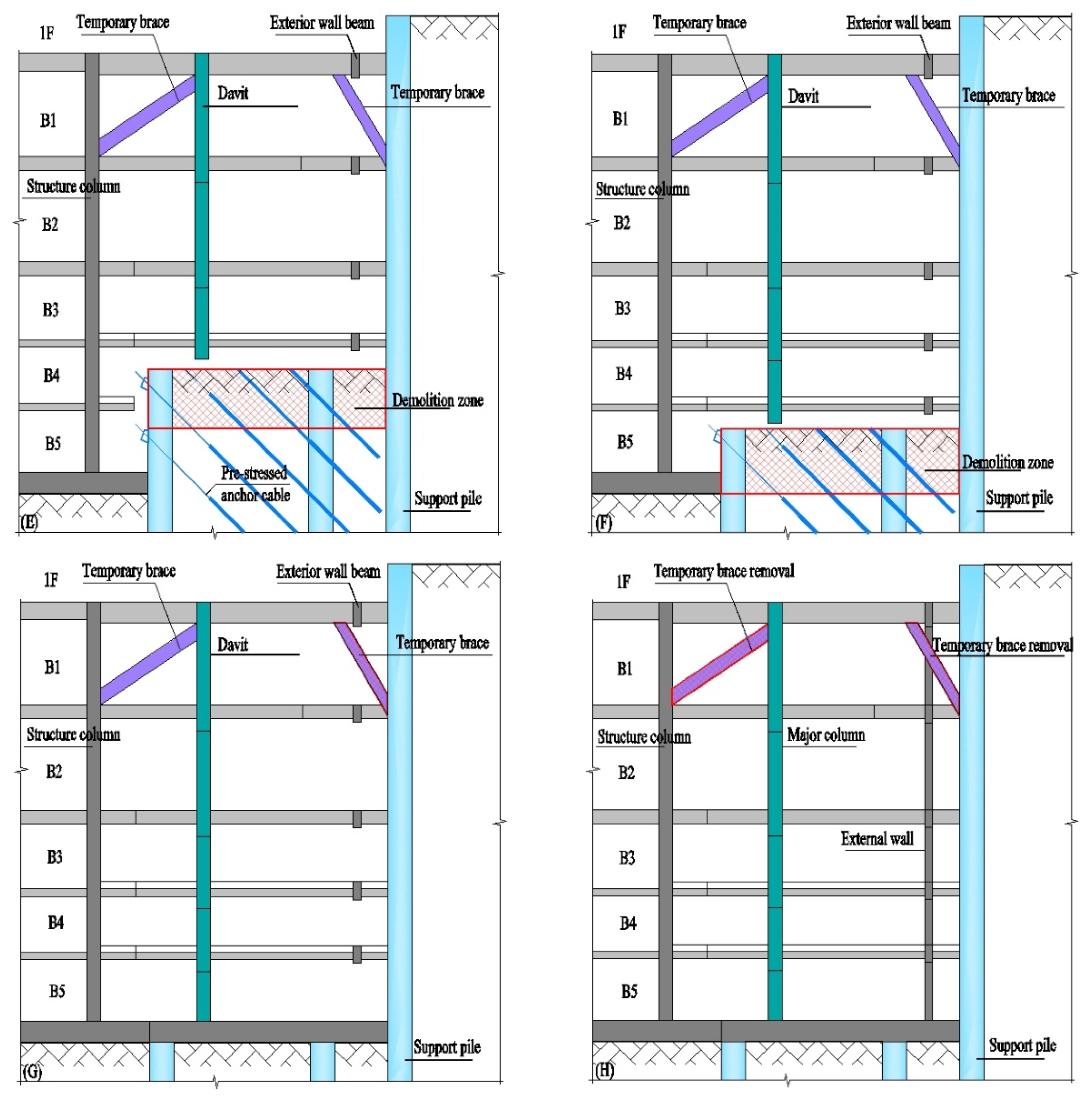
When the basement was constructed by the top-down method within the three-row pile area, the horizontal structure was first constructed from top to bottom, and then the vertical structure was constructed from bottom to top after the footing slab was constructed. At the same time, the second and third rows of piles and related supporting structures in this area were gradually removed from top to bottom. Prior to the construction of the vertical structure, the horizontal structure of the footing slab lacked vertical support, so in order to compensate for the problem of insufficient bearing capacity of the footing slab, some temporary structures, such as walls, columns, beams, diagonal braces, etc., were added at the edge of the structure.
The removal and collaborative construction of a three-row pile and basement is shown in
Figure 9.
5. Analysis of the Cooperative Effect between Underground Structures and Supporting Structures in the Top-Down Area
5.1. Load and Material Settings
5.1.1. Load Setting
(1) Constant load
The capacity of reinforced concrete: 26 kN/m3; the capacity of steel: 78 kN/m3; the capacity of fill stratum: 18 kN/m3. The top slab of the basement is considered to be 600 mm of filler surface layer in the construction stage, and the weight is 10.8 kN/m2. For the rest of the underground structures of each floor, the constant load in the construction stage is only considered to be the structural self-weight.
(2) Live load
The top plate of the basement is considered to be traveling flatbed truck, and the live load is taken as 100 kN/m2.
(3) Wind load
Basic wind pressure is considered according to one in 10 years, 0.45 kN/m2.
5.1.2. Load Combination
The design value of the load combination during the construction phase was considered to be mainly controlled by variable loads, and the following formulae were selected according to the load specification.
where
—Sub-component factor for permanent loads;
—Sub-factors for variable loads;
—Standard value of permanent loads;
—Standard value of variable loads;
—Combination value coefficient of variable load;
—Adjustment factor for variable loads to account for design life.
The design value of the standard combined effect of loads during the construction phase was based on the following formula selected from the load specification.
The load combination factors considered during the construction phase are detailed in
Table 3.
5.1.3. Material Setup
Values of strength grades of concrete materials are shown in
Table 4.
5.2. Basic Calculation Assumption
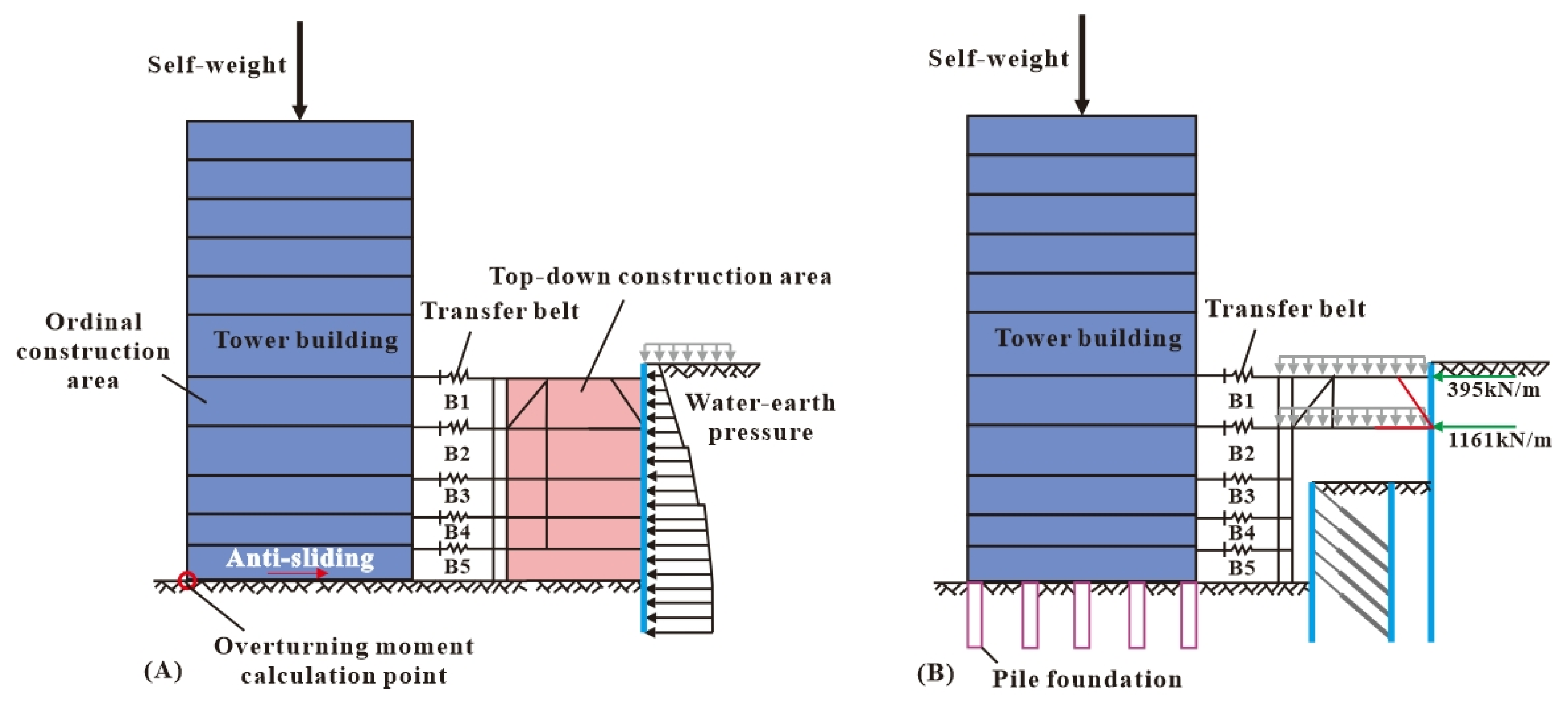
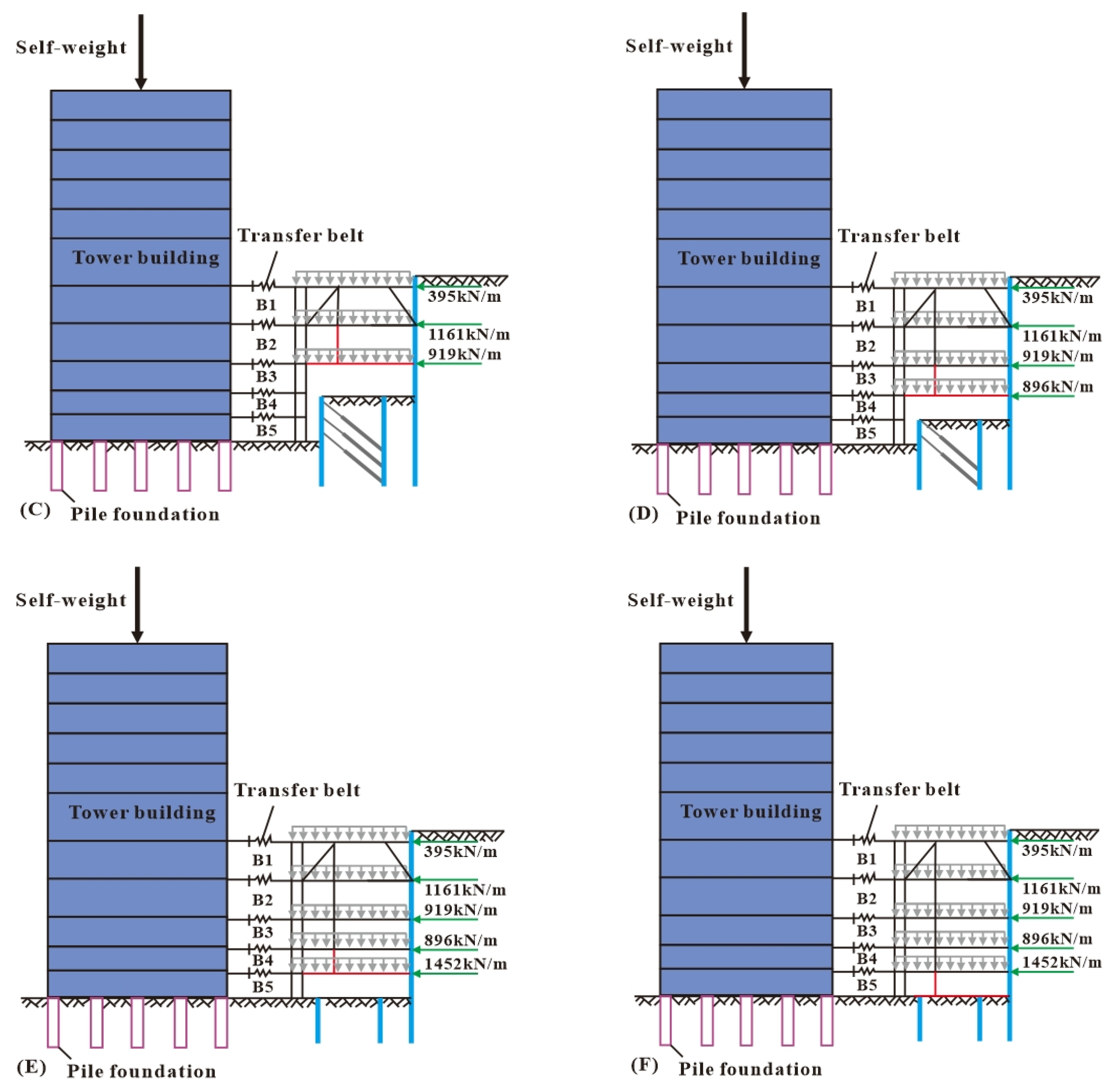
During the construction stage of the top-down area, the main basement structure and the outermost supporting piles were considered to work together, and it was assumed that the bottom of the tower building was an immovable point, and the supporting piles formed an elastic bearing constraint under the action of the basement structure. According to the construction sequence of the underground structure in the top-down area described in
Section 4, and the following assumptions, the distribution model of the basement structure and the grading loading sketch were simulated (see
Figure 10).
(1) Modeling of the whole basement included the ordinary construction area, the top-down construction area, and the outermost support pile, and considered the deformation coordination among the three;
(2) The construction loads considered the self-weight of the structure, the live load, and the water and soil pressure during the construction period. The wind load was considered as 1 in 10 years, and the seismic effect was not considered;
(3) The loading sequence of the ordinary construction area shall be loaded layer by layer from bottom to top, and the top-down construction area shall be loaded layer by layer from top to bottom. The soil and water pressure shall be loaded layer by layer according to the progress of the demolition of the supporting piles;
(4) The floor slab was assumed to the elastic slab and bears the axial force and bending moment together with the beam;
(5) The connection between the top of the pile of the tower building and the bearing platform was assumed to be articulated;
(6) The connection between the beam plate and the supporting pile in the top-down area was assumed to be articulated;
(7) The force-transmitting steel beam was assumed to be hinged at both ends and to transmit only the axial force.
5.3. Analysis of Deformation and Stability of Ultra-High-Rise Tower Building
5.3.1. Analysis of the Antioverturning Stability of Ultra-High-Rise Tower Building
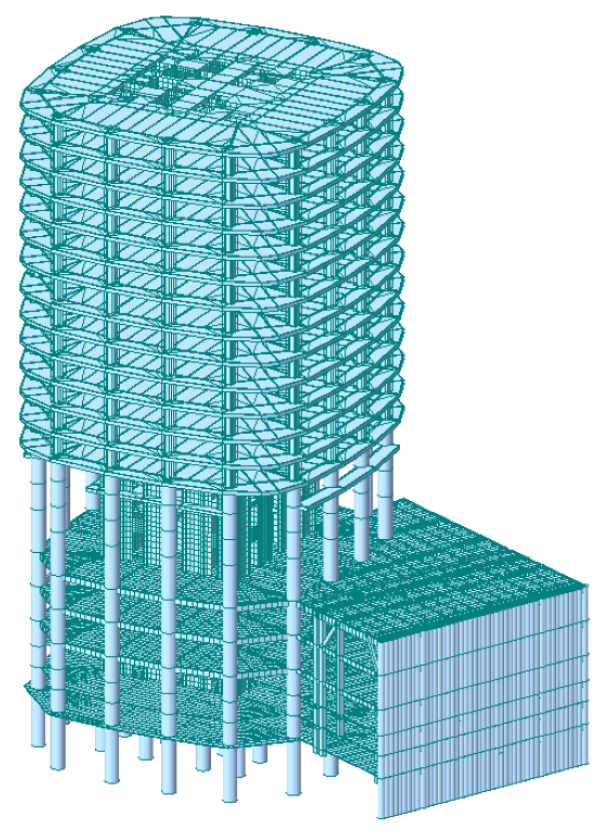
The finite element software of the Midas Gen 2019 sed to establish a three-dimensional model (see
Figure 11) to calculate and analyze the antioverturning stability of the tower building, and the basic assumptions of the model, boundary conditions, and external loading were detailed in the previous section. The pile foundation was modeled by the beam element in the Midas Gen, which is given a cross-sectional diameter to provide 3D property, and the bottom of pile foundations are restrained by translation and rotation. Similarly, the floors and walls are simulated by the plate elements with a certain thickness.
The corner point of the base plate of the tower was the tilting moment action point, the tilting moment acting on the main structure was the water-soil pressure coming from the outermost supporting piles, and the tilting moment was generated by the self-weight of the main structure. The basic calculation sketch of the model and the load grading and loading sketch are shown in
Figure 10. Referring to specification GB50007-2011 [
23], the stability coefficient of overturning resistance is 1.6, and the stability coefficient of slip resistance is 1.3.
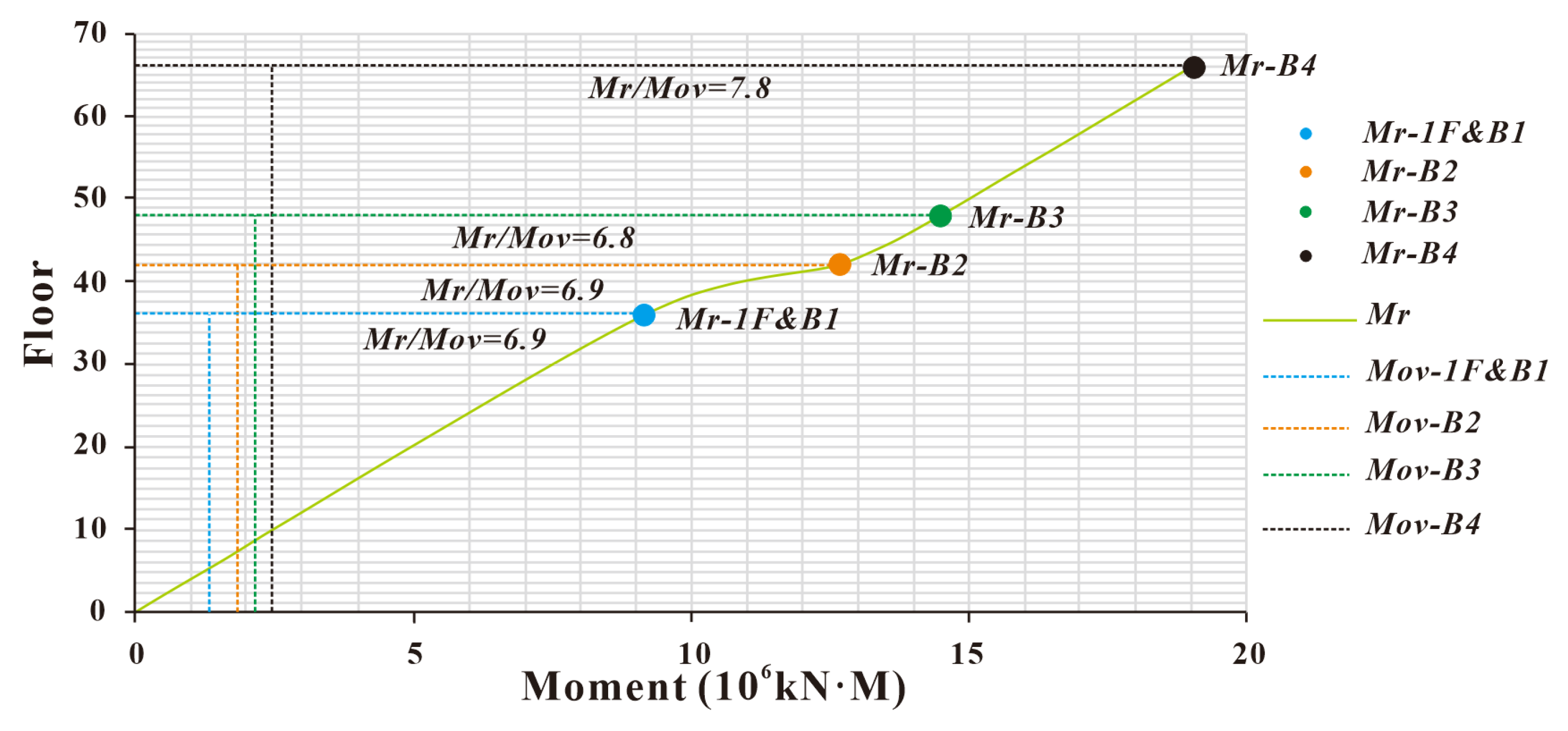
The relationship between the overturning moment and antioverturning moment of the tower building under the action of soil and water pressure was obtained by calculation, as shown in
Figure 12. During the construction phase, the corresponding construction schedule was formulated according to the antioverturning moment diagram of the tower building. As shown in
Figure 12, when the 1F and B1F were constructed in the top-down area, and the tower building was constructed up to the 36F, the antioverturning coefficient of the tower was 6.9. The antioverturning coefficient of the tower building was 6.9 when the B2F was constructed in the top-down area and the tower building was constructed up to the 42F. The antioverturning coefficient of the tower was 6.8 when the B3F was built in the top-down area and the tower building was built up to the 48F. When the B4F was constructed in the top-down area and the tower building was constructed up to the 66F, the antioverturning coefficient of the tower building was 7.8, indicating that the antioverturning ability of the ultra-high-rise tower building had sufficient safety guarantee.
5.3.2. Analysis of Pile-Bearing Capacity of Ultra-High-Rise Tower Building
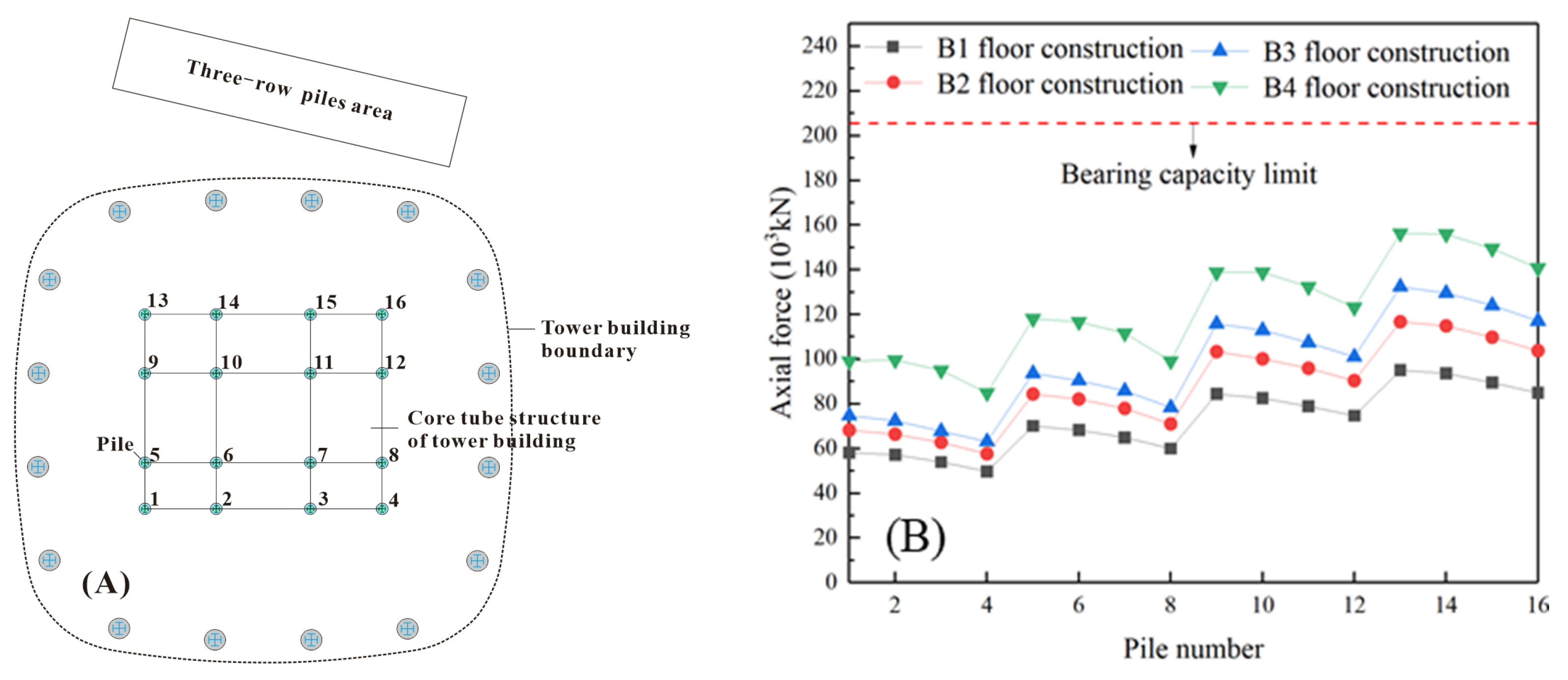
The foundation of the ultra-high-rise tower building is large diameter hand-dug piles with a core slab thickness of 3.5 m. According to the geotechnical investigation report and field verification, the bottom of most of the raft slabs was moderately weathered granite. In order to simulate the change of axial force of the pile foundation with the construction process and its relationship with the bearing capacity of the pile foundation, the locations of the pile foundations were numbered in the finite element model, where the locations of pile foundations No. 4, No. 8, No. 12, and No. 16 were close to the top-down area of the three-row pile, while the locations of pile foundations No. 1, No. 5, No. 9, and No. 13 were far from the top-down area of the three-row pile (see
Figure 13A).
As shown in
Figure 13B, the axial force of the pile foundation of the tower building showed an uneven distribution pattern with the change of the construction process of the upper tower structure and the reverse zone. The overall performance was that the axial force away from the area of the three-row pile was large (1, 5, 9, 13), and the axial force near the area of the three-row pile was small (4, 8, 12, 16), which was aligned with conventional understanding. By the comparison of the data, it could be seen that the axial force of the same pile foundation gradually increased with the construction of the basement of the three-row pile in the top-down area, while the axial force of the pile foundation increased irregularly with the increase in the construction floors of the tower building. The maximum axial force of the pile top was about 155,000 kN, which was far lower than the limit value of the pile-bearing capacity of about 205,000 kN, indicating that the pile foundation of the tower building at the construction stage of the basement of the top-down area was absolutely safe.
5.3.3. Lateral Deformation Analysis of Ultra-High-Rise Tower Building
The structural system of the tower building is “steel frame and reinforced concrete core structure”, and the tower building bore the role of the horizontal thrust of the pit support. The overturning moment borne by the core under the horizontal force accounts for more than 85%. Therefore, the core cylinder was selected as the research object to analyze the deformation of the tower building during the construction of top-down area. The monitoring points of the horizontal displacement of the corner points of the core cylinder are shown in
Figure 14A.
As shown in
Figure 14B, the maximum lateral deformation of the core cylinder of the tower building was 11.7 mm under the action of water and soil pressure, and the maximum displacement angle between floors was about 1/2100. The horizontal deformation of the core cylinder corner points A and C was larger than that of points B and D, and as the basement was continuously constructed downward, the lateral deformation of each corner point of the core cylinder increased. In general, the lateral displacement of the basement was small, but the overall rotation of the tower caused by the impact on the superstructure should not be ignored and should be corrected layer by layer during the construction.
5.3.4. Stress Analysis of the Members of Ultra-High-Rise Tower Building
The core cylinder was selected as the research object, and the compressive stress distribution and shear stress distribution of the core cylinder under each construction process under the action of soil and water pressure and the self-weight of the upper construction floor were statistically analyzed, and the results are shown in
Table 5 and
Table 6.
As shown in
Table 5 and
Table 6, the distribution of compressive stress in the shear wall of the core cylinder under the action of soil and water pressure and the self-weight load of the superstructure was not uniform, ranging from 8 to 26 MPa, which showed that it increased when it was far from the area of the three-row pile and decreased when it was close to the area of the three-row pile, but none of them showed tensile stress. The shear stress was mainly distributed on the shear wall perpendicular to the direction of pit support, and the maximum value of the stress at the bottom was between 1.67~3.66 MPa, showing the trend of small at the top and large at the bottom. The stress distribution pattern was consistent with the force mechanism, indicating the establishment of the assumptions of the model calculation.
5.4. Analysis of Forces on Underground Structural Elements
Taking the typical span combined truss in the top-down area as the analysis object, the force and deformation law of the members in the top-down area at each construction stage were studied, and the calculation results are shown in
Table 7. The maximum axial force of the beam and diagonal bracing was 2369 kN and 4951 kN, respectively. The maximum vertical displacement of the davit was 7.9 mm. The maximum axial force of the truss member gradually increased with the construction sequence of each layer, the maximum axial force of the beam reached 2505 kN, and the maximum vertical deformation of the davit was 11.7 mm, which was smaller than the control requirement of the specification for settlement difference of frame structure.
6. Conclusions
In this paper, a three-row pile support structure and its cooperative construction method with the basement of the main structure were proposed for an ultra-deep fill pit adjacent to a sensitive building, and the following main conclusions were drawn:
The three-row pile support system proposed in this paper provided a new type of deep foundation pit support, and its unique step-type structural form provided enough space for the construction of prestressing anchors, which solved the problem of construction line encroachment in close proximity to sensitive buildings.
The results of stability calculation and finite element analysis of the three-row piles showed that the three-row pile support system had stronger overturning resistance and larger support stiffness, which could effectively control the deformation of ultra-deep foundation pits, especially suitable for deep foundation pits with thick fill layers.
The orientation of the prestressing anchor cable had a significant effect on the effect of three-row pile support, in which the oblique anchor cable and three-row pile joint support had the best effect on controlling deformation, followed by the horizontal anchor cable, and the vertical anchor cable was worst. Therefore, the oblique anchor cable was recommended in the three-row pile support system.
The cooperation construction technology of three-row pile and basement proposed in this paper utilized the beam and plate structure of the first floor and B1 floor basement in the top-down area, and formed a large-span concrete truss structure by adding two sets of temporary diagonal rods, so that the vertical load-bearing capacity of the structure in the top-down area was increased by ~400%. This method could fully utilize the construction space, accelerate the construction progress, and save the construction cost on the basis of meeting the needs of foundation pit support, which provides valuable experience for the design and construction of deep foundation pits in similar projects.
Currently, research on three-row piles is limited to theoretical studies, with a lack of research on model testing. Therefore, it is necessary to conduct model tests to study the action mechanism and potential failure process of the three-row piles in the future. In addition, the vibration isolation performance of three-row piles should be investigated in the future. The isolation effect of the multirow pile isolation barrier system mainly depends on the number of pile rows, so the isolation effect of the three-row pile support structure in reducing the foundation pit disturbance caused by vehicle vibration can be further studied.
Author Contributions
Y.Z.: conceptualization, methodology, validation, analysis, writing—original draft; X.Z.: validation, analysis; D.W.: validation, investigation; L.Z.: conceptualization, validation; L.H.: conceptualization, investigation; H.Q.: writing—review and editing. All authors have read and agreed to the published version of the manuscript.
Funding
This manuscript was supported by the R&D Program of China Construction Second Engineering Bureau Co., Ltd. (Grant No. 2021ZX000001).
Data Availability Statement
The original contributions presented in the study are included in the article, further inquiries can be directed to the corresponding author.
Conflicts of Interest
All authors were employed by the company China Construction Second Engineering Bureau Co., Ltd. The authors declare that the research was conducted in the absence of any commercial or financial relationships that could be construed as a potential conflict of interest. The authors declare that this study received funding from China Construction Second Engineering Bureau Co., Ltd. The funder was not involved in the study design, collection, analysis, interpretation of data, the writing of this article or the decision to submit it for publication.
References
- Zhang, W.G.; Zhang, Y.M.; Goh, T.C. Multivariate adaptive regression splines for inverse analysis of soil and wall properties in braced excavation. Tunn. Undergr. Space Technol. 2017, 64, 24–33. [Google Scholar] [CrossRef]
- Goh, A.T.C.; Zhang, W.G.; Wong, K.S. Deterministic and reliability analysis of basal heave stability for excavation in spatial variable soils. Comput. Geotech. 2019, 8, 152–160. [Google Scholar] [CrossRef]
- Qin, H.L.; Huang, J.; Li, Q.Z.; Hu, L.X.; Shi, Y.J. Analysis of influencing factors of deep foundation pit deformation in deep silt formation. Chin. J. Geotech. Eng. 2021, 43, 23–26. [Google Scholar]
- Tschebotarioff, G.P. Foundations, Retaining and Earth Structures; MC Graw-Hill: New York, NY, USA, 1973. [Google Scholar]
- Oteo, C.S. Discussion of analysis of piles in soil undergoing lateral movement by Harry G. Poulos. J. Geotech. Eng. Div. 1974, 100, 464–467. [Google Scholar] [CrossRef]
- Paik, K.H. Estimation of active earth pressure against rigid retaining walls considering arching effect. Geotechnique 2003, 53, 643–653. [Google Scholar] [CrossRef]
- Zheng, G.; Li, X.; Liu, C. Double-row pile analysis considering pile-soil interaction. J. Build. Struct. 2004, 25, 99–106. [Google Scholar]
- Ying, H.W.; Chu, Z.H.; Li, Y.B. Research on calculation method and engineering application of double row pile support structure. Rock Soil Mech. 2007, 28, 1145–1150. [Google Scholar]
- Cao, J.; Jiang, K.Y.; Gui, Y. Research on Calculation Theory of Double-Row Piles Retaining Structure. Adv. Mater. Res. 2013, 671–674, 251–256. [Google Scholar] [CrossRef]
- Zhu, Q.K. Analysis and Research on Some Problems of Double-Row Pile Supporting Structure System of Deep Foundation Pit. Ph.D. Thesis, South China University of Technology, Guangzhou, China, 2013. [Google Scholar]
- Xie, W.; Sun, L.M. Experimental and computational assessment of shear beams as earthquake resilient measure for double-column piers supported by pile-group. Eng. Struct. 2021, 242, 112509. [Google Scholar] [CrossRef]
- Wang, Y.D.; Ibarra, L.; Pantelides, C. Seismic Retrofit of a Three-Span RC Bridge with Buckling-Restrained Braces. J. Bridge Eng. 2016, 21, 04016073. [Google Scholar] [CrossRef]
- Ma, Y.; Long, X.D.; Li, S. Terraced Support Structure of Three Row Piles and Single Row Piles. CN Patent 205012, 3 February 2016. [Google Scholar]
- Xin, J.P.; Tang, X.S.; Zheng, Y.R. Large-scale model test of single-row and three-row micro anti-slide piles. Rock Soil Mech. 2015, 36, 1050–1056. [Google Scholar]
- Tian, Z.Q.; Shen, B.G.; Liu, N.S. Finite element calculation of three-row pile supporting structure in high and deep bank slope project. China Water Transp. 2016, 16, 291–295. [Google Scholar]
- Qian, D.X.; Liu, W.Y. Analysis of force checking calculation of three-row pile support in Wushen Canal Section based on pile-spring model. China Water Transp. 2019, 05, 63–64. [Google Scholar]
- Cao, Z. Research on Internal Force and Deformation of Three-Row Pile Supporting Structure in Deep Foundation Pit. Master’s Thesis, Wuhan University of Technology, Wuhan, China, 2017. [Google Scholar]
- Wei, Z. Analytical Calculation and Numerical Analysis of Three-Row Pile Support Structure Based on Pile-Soil Coupling. Master’s Thesis, Hunan University, Changsha, China, 2019. [Google Scholar]
- Zhang, H. Study on Deformation and Internal Force of Three-Row Pile Support System in Deep Foundation Pit Excavation. Master’s Thesis, China Three Gorges University, Yichang, China, 2019. [Google Scholar]
- JGJ 120-2012; Technical Regulations for Building Foundation Pit Support. China Building Industry Press: Beijing, China, 2012.
- GB 50330-2013; Construction Slope Engineering Technical Code. China Building Industry Press: Beijing, China, 2013.
- Zhu, Y.X.; Wei, D.S.; Zhai, L. Construction technology and deformation analysis of underground space excavation with reverse method. Constr. Technol. 2024, 53, 39–45. [Google Scholar]
- GB50007-2011; Code for Design of Building Foundation. China Building Industry Press: Beijing, China, 2011.
Figure 1.
Plan of the north side project.
Figure 1.
Plan of the north side project.
Figure 2.
Design of the three-row pile support structure on the north side of the pit: (A) Plan of the three-row pile support system; (B) section of three-row pile support system.
Figure 2.
Design of the three-row pile support structure on the north side of the pit: (A) Plan of the three-row pile support system; (B) section of three-row pile support system.
Figure 3.
Schematic diagram of three-row piles calculation mode: (A) Simplified calculation model; (B) calculated widths of soil pressure (bs, b0).
Figure 3.
Schematic diagram of three-row piles calculation mode: (A) Simplified calculation model; (B) calculated widths of soil pressure (bs, b0).
Figure 4.
Schematic diagram of three-row piles for overturning stability calculation.
Figure 4.
Schematic diagram of three-row piles for overturning stability calculation.
Figure 5.
Finite element model of three-row pile support system.
Figure 5.
Finite element model of three-row pile support system.
Figure 6.
Comparison between simulated and monitored deformation of three-row pile: (A) Horizontal deformation; (B) vertical deformation.
Figure 6.
Comparison between simulated and monitored deformation of three-row pile: (A) Horizontal deformation; (B) vertical deformation.
Figure 7.
Calculation results of deformation and internal force of three-row pile support system: (A) Horizontal deformation of oblique anchors; (B) vertical deformation of oblique anchors; (C) horizontal deformation of horizontal anchors; (D) vertical deformation of horizontal anchors; (E) horizontal deformation of vertical anchors; (F) vertical deformation of vertical anchors; (G) horizontal deformation of three-row piles with different orientations of anchor cables; (H) vertical deformation of soil in areas I, II, and III with different orientations of anchor cables; (I) maximum shear force of the piles; (J) maximum bending moment of piles.
Figure 8.
Schematic diagram of the positional relationship between the tower building and the basement structure in the top-down construction area.
Figure 8.
Schematic diagram of the positional relationship between the tower building and the basement structure in the top-down construction area.
Figure 9.
Construction sequence of the cooperative construction of three-row pile and basement in the top-down area: (A) Completion of the construction of the ordinary construction area; (B) construction of the 1F base plate and partial footing of the B1F in the top-down construction zone; construction of temporary diagonal bracing and davit on the B1F, and removal of the red zone support structure at the B1F; (C) construction of the remaining portion of the base plate at the B1F and removal of the red zone supporting piles at the B2F; (D) construction of B2F base plate and davit, removal of the red zone piles at the B3F; (E) construction of B3F base plate and davit, removal of the red zone supporting piles at the B4F; (F) construction of B4F base plate and davit, removal of the red zone supporting piles at the B5F; (G) construction of B5F base plate and davit; (H) construction of external wall, removal of temporary bracing.
Figure 10.
Basic assumption of cooperation bearing and loading sketch for top-down construction zone: (A) Basic calculation assumptions of cooperative bearing between basement structures and exterior support piles; (B) construction of the 1F and B1F in the top-down construction area; (C) construction of the B2F in the top-down construction area; (D) construction of the B3F in the top-down construction area; (E) construction of the B4F in the top-down construction area; (F) construction of the B5F in the top-down construction area.
Figure 11.
Finite element model of ultra-high-rise tower building and basement.
Figure 11.
Finite element model of ultra-high-rise tower building and basement.
Figure 12.
Curve of antioverturning stability capacity of ultra-high-rise tower building.
Figure 12.
Curve of antioverturning stability capacity of ultra-high-rise tower building.
Figure 13.
Statistical analysis of the piles in tower building: (A) Numbering of piles for core tube structure of the ultra-high-rise tower building; (B) axial force of the piles in tower building.
Figure 13.
Statistical analysis of the piles in tower building: (A) Numbering of piles for core tube structure of the ultra-high-rise tower building; (B) axial force of the piles in tower building.
Figure 14.
Lateral deformation analysis of ultra-high-rise tower building core: (A) Deformation and monitoring point of tower building core under the water and soil pressure; (B) displacement of tower building core corner points under the water and soil pressure.
Figure 14.
Lateral deformation analysis of ultra-high-rise tower building core: (A) Deformation and monitoring point of tower building core under the water and soil pressure; (B) displacement of tower building core corner points under the water and soil pressure.
Table 1.
Antioverturning and antislip stability calculation of the three-row pile structure.
Table 1.
Antioverturning and antislip stability calculation of the three-row pile structure.
| G1 (kN/m) | G2 (kN/m) | d1 (m) | d2 (m) | a (m) | b (m) | B (m) | Eak (kN/m) | Epk (kN/m) |
|---|
| 6087.36 | 2652.64 | 5.42 | 12.10 | 3.67 | 13.50 | 15.10 | 6422.65 | 14,680.9 |
| Antioverturning meets the specification [20] |
| Antisliding meets the specification [21] |
Table 2.
Physical and mechanical parameters of the soil layer.
Table 2.
Physical and mechanical parameters of the soil layer.
| Soil Layer | Fill Stratum | Gravel Clay | Completely Weathered Granite | Intensely Weathered Granite | Moderately Weathered Granite |
|---|
| Thickness/(m) | 17.8 | 2.4 | 2.4 | 9.1 | 23.3 |
| 18.0 | 19.0 | 26.7 | 26.7 | 26.7 |
| 10.0 | 20.0 | 60.0 | 180.0 | - |
| 10.0 | 20.0 | 60.0 | 180.0 | - |
| 60.0 | 80.0 | 240.0 | 720.0 | - |
| 25.0 | 22.0 | 35.0 | 50.0 | 1600 |
| 12.0 | 28.0 | 25.0 | 35.0 | 52.0 |
Table 3.
Values of load combination factors during construction phase.
Table 3.
Values of load combination factors during construction phase.
| Load Category | Sub-Component Coefficients
| Combined Coefficients
|
|---|
| Constant load | 1.2 | 1.0 |
| Live load | 1.4 | 0.7 |
| Water and soil pressure | 1.4 | 0.7 |
| Wind load | 1.4 | 0.7 |
Table 4.
Strength values for concrete members.
Table 4.
Strength values for concrete members.
| Building Category | Concrete Member Category | Standard Compressive Strength of Concrete Cube (MPa) |
|---|
| Super-tall tower building | Walls and columns | 60 |
| Beam and plates | 35 |
| Baseplates | 40 |
| Piles | 50 |
| Basement | Walls and columns | 40 |
| Beam and plates | 35 |
| Baseplates | 40 |
Table 5.
Compressive stress statistics of core corner points of the ultra-high-rise tower building.
Table 5.
Compressive stress statistics of core corner points of the ultra-high-rise tower building.
| Construction Sequence | Compressive Stress σ (MPa) |
|---|
| A | B | C | D |
|---|
| Construction of 1F and B1F | −10 | −8 | −14 | −9 |
| Construction of B2F | −13 | −10 | −18 | −11 |
| Construction of B3F | −15 | −11 | −23 | −12 |
| Construction of B4F | −15 | −18 | −26 | −15 |
Table 6.
Shear stress statistics of core corner points of the ultra-high-rise tower building.
Table 6.
Shear stress statistics of core corner points of the ultra-high-rise tower building.
| Construction Sequence | Shear Stress τ (MPa) |
|---|
| A | B | C | D |
|---|
| Construction of 1F and B1F | 1.90 | 2.30 | 1.95 | 1.67 |
| Construction of B2F | 2.30 | 2.60 | 2.66 | 1.9 |
| Construction of B3F | 2.60 | 3.10 | 3.33 | 2.33 |
| Construction of B4F | 3.05 | 3.30 | 3.66 | 2.67 |
Table 7.
Analysis results of internal forces and displacements of underground beam-column members in the top-down area.
| Disclaimer/Publisher’s Note: The statements, opinions and data contained in all publications are solely those of the individual author(s) and contributor(s) and not of MDPI and/or the editor(s). MDPI and/or the editor(s) disclaim responsibility for any injury to people or property resulting from any ideas, methods, instructions or products referred to in the content. |
© 2024 by the authors. Licensee MDPI, Basel, Switzerland. This article is an open access article distributed under the terms and conditions of the Creative Commons Attribution (CC BY) license (https://creativecommons.org/licenses/by/4.0/).


