Article

Structural Behavior of Precast Monolithic Composite Beams with ECC Prefabricated Shells

Shaanxi Key Laboratory of Safety and Durability of Concrete Structures, Xijing University, Xi’an 710123, China
*
Author to whom correspondence should be addressed.
Buildings 2024, 14(4), 1024; https://doi.org/10.3390/buildings14041024
Submission received: 19 February 2024 / Revised: 28 March 2024 / Accepted: 4 April 2024 / Published: 6 April 2024
(This article belongs to the Section Building Structures)

Abstract

:
Engineered Cementitious Composite (ECC) was used in the prefabricated shell of a precast composite beam, and the validity of the ECC in the precast monolithic composite beam’s flexural performance was studied. Flexural performance tests were conducted on six specimens to analyze their failure state, failure mechanism, bearing capacity, and deformation capacity. Compared with the Reinforced Concrete (RC) prefabricated shell composite beam, the ECC prefabricated shell composite beam showed a higher bearing capacity and lower damage degree. The yielding load of specimen PSMCB−1 increased by 5.6%. The maximum load of specimen PSMCB−1 reached 256.6 kN, having increased by 8.1%. When the tests stopped, the maximum crack width of specimen PSMCB−1 was 4.1mm, while the maximum crack width of specimen PSMCB−6 reached 9.0 mm. The ECC material in the prefabricated shell also delayed the yielding of the steel bars in the shell.

1. Introduction

With the development of prefabricated buildings, prefabricated concrete structures have an established prefabricated concrete structure system with “equivalent cast in situ” as the basic design concept. This structural system draws on and relies on the characteristics of “integral,” which promotes the rapid development and application of prefabricated concrete structures. In the prefabricated structure, the use of composite components can reduce the weight of the assembled component to facilitate lifting, and the integrity of the structure is also relatively good because of the existence of post-poured concrete. The research and application of composite components have a long history, and such components are used in new buildings, bridge structures, reinforcement, and building reconstruction. The research on composite components is relatively sufficient, including the shear slip of overlapping surfaces, their overall mechanical properties, and their shear properties.
Engineered Cementitious Composites (ECCs) have the characteristics of tensile strain hardening and microcrack development. Using ECC material in Reinforced Concrete (RC) structures could improve the mechanical performance of the structures [1,2]. To further investigate the mechanical performance of composite components, researchers have applied ECC materials to composite components, and a large number of studies have been carried out on ECC materials, precast monolithic structures, and composite beams. Researchers [3,4,5] formed composite beams by combining RC beams with ECC, using three different reinforcement methods to study the flexural properties. The flexural capacity of the composite beams was significantly enhanced, and the shear resistance and deformability were also improved. The flexural capacity of the composite beam with three sides reinforced was the highest. Other researchers [6,7,8] arranged ECC materials and classic concrete in layers in beams to study their flexural properties. Increasing the thickness of the ECC layer significantly improved the structure’s bending performance and bearing capacity and effectively controlled and dispersed the cracks in the upper layer. This provided an effective technical means to improve the durability of the RC structure. Nguyen [9] studied the mechanical behavior of common concrete beams and six composite beams composed of ECC. The ECC material used in the compression or tension region had a good effect on improving the bearing capacity. At the same time, the flexural bearing capacity of the beams was estimated through the cross−sectional analysis method.
Liang Xingwen et al. [10] and Wang et al. [11] used ECC as permanent formwork to form a composite beam and carried out flexural performance tests on the beams. Compared with those of the common concrete beams, the flexural capacity, cracking load, and crack resistance of the ECC formwork composite beams were higher. The crack developing rate and width of the composite beams using ECC material as permanent formwork were reduced. In order to enhance the durability of RC structures, several researchers [12,13] proposed a new method by introducing a composite beam with U-shaped ECC permanent formwork. Compared with RC beams, the ECC/RC composite beams showed improved deformability, bearing capacity, and failure durability. Zhang et al. [14] investigated the shear properties of stirred-free RC beams with prefabricated U-shaped ECC permanent formwork. The results showed that the shear bearing capacity of the beam was significantly improved by using ECC permanent formwork. Zhang et al. [15] studied the shear performance of UHPC-NC (Ultra-High-Performance Concrete–Normal Concrete) composite beams with UHPC formwork. The results showed that the shear bearing capacity of the U-shaped UHPC formwork for the composite beam was significantly improved. Also, several studies [16,17] showed that applying a layer of ECC could increase the maximum load and impact the minimum reinforcement requirements. Carlos Zanuy [18] conducted an impact experiment on RC beams strengthened with a thin layer of ECC. The shear forces and bending moment of the composite RC-ECC elements under impact force were improved.
As mentioned above, researchers have improved the flexural behavior of composite beams by replacing common concrete with layers or using prefabricated formwork in ECC materials. There have been few studies on the application of ECC to prefabricated structures. In this research, to enhance the mechanical performance of precast monolithic composite beams, ECC material was used to prefabricate shells for the composite beams, together with a welded steel mesh. Then, the post-poured concrete was placed in the prefabricated shell to form a new ECC prefabricated shell precast monolithic composite beam. The mechanical characteristics of ECC material are different from those of concrete, and the new structural form differs from the composite beams previously examined; thus, the flexural properties and failure mechanism of the ECC prefabricated composite beam were experimentally studied. This study has important theoretical significance and engineering application value for improving the performance of precast monolithic structures.

2. Materials and Methods

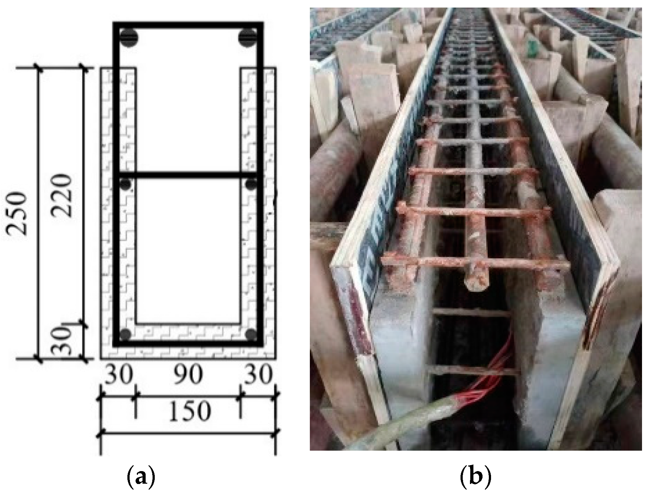
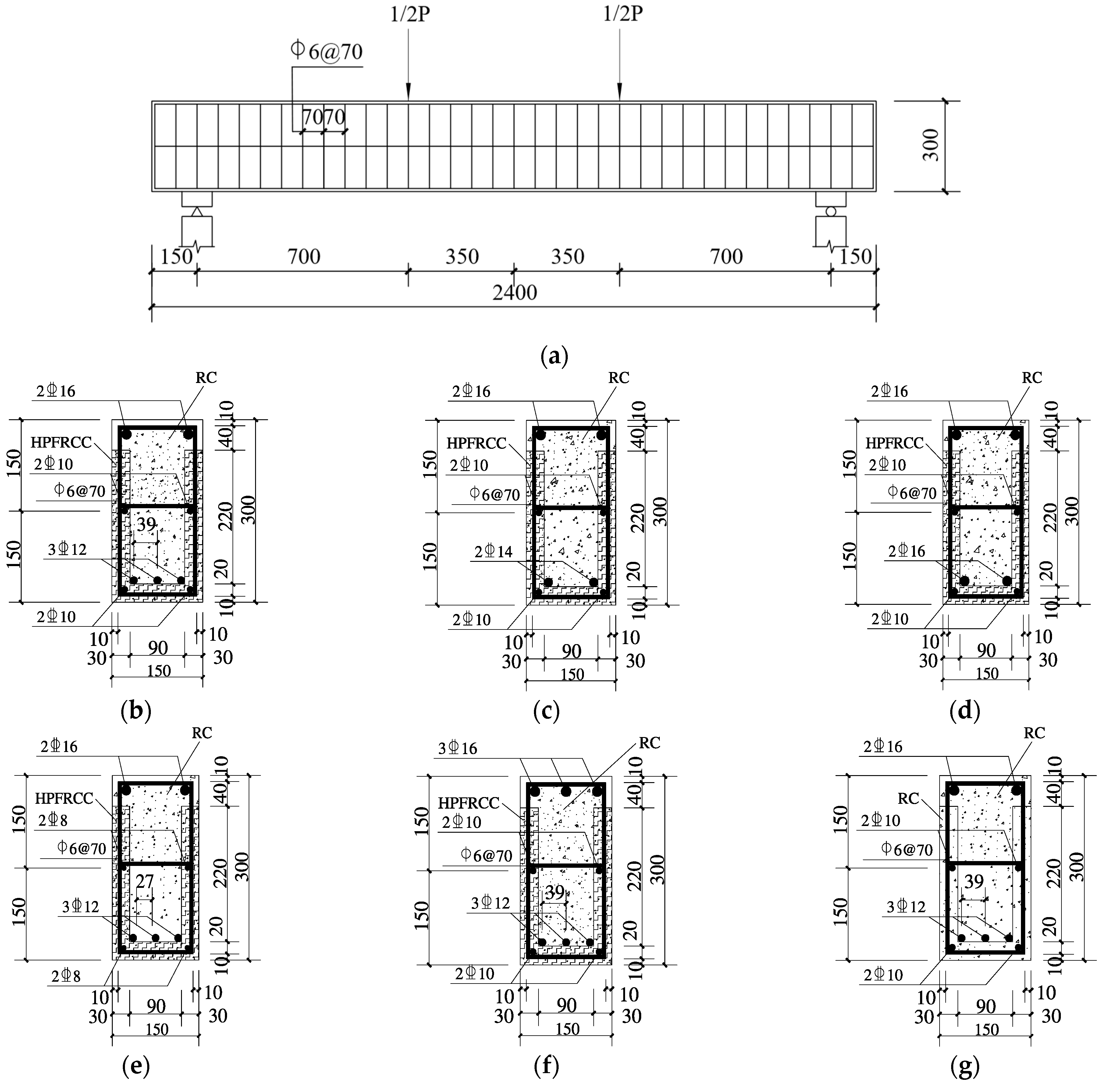
2.1. Specimen Design

According to the research requirements, six precast monolithic composite beams were designed to study their mechanical behaviors. There were five specimens of ECC prefabricated shell composite beams, which were numbered PSMCB-1~PSMCB-5. The influencing factors in the flexural behavior were the reinforcement ratio in the prefabricated shell and the rebar reinforcement ratio in the post-cast concrete. The upper part of the frame beam would be tensile under reciprocating loads during earthquakes. Therefore, a reverse-loading test specimen (PSMCB-5) was designed for the test. Specimen PSMCB-6 had the same parameters as the ECC composite beam PSMCB-1, except that the material of the precast shell was common concrete. The two specimens were compared to study the validity of the ECC material in the composite beam’s flexural performance. In the specimen names, “PSMCB” indicates the prefabricated shell monolithic composite beam. The cross−sectional dimensions of the composite beam were 150 mm × 300 mm, the thickness of the prefabricated shell was 30 mm, and the length of the specimen was 2.4 m. The parameters of the composite beams are listed in Table 1. Detailed information on the precast monolithic structures is presented in Figure 1.
To make the specimens, the shells were poured first, and the welded reinforcement mesh was then poured into the prefabricated shell, as shown in Figure 2. Then, the longitudinal reinforcement bars were placed in the prefabricated shell. Finally, the post-cast concrete was poured. Then, the specimens were naturally cured. Cube blocks, prism blocks, and dumbbell tensile specimens were reserved at the same time. They were cured under the conditions for composite beams.

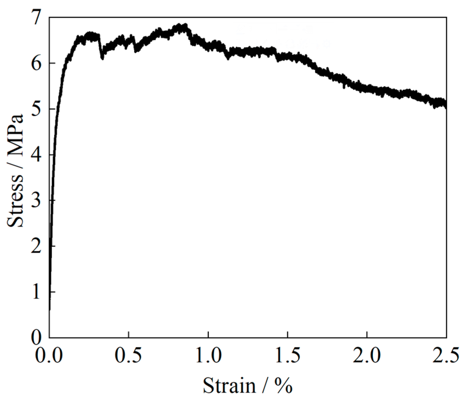
2.2. Mechanical Properties of Materials

The prefabricated shell was made of ECC or common concrete. The post-cast concrete was ready-mixed concrete. The ECC was made of cement, fly ash, quartz sand, PVA fibers, and water. The cement was P·O. 42.5 ordinary Portland cement. The fly ash grade was first class. The particle size of the quartz sand was 0.06 mm~1.18 mm. The PVA fiber was KURALINK−II−12 mm polyvinyl alcohol fiber. The performance indicators of the PVA fiber were as follows: length, 12 mm; diameter, 40 μm; tensile strength, 1560 MPa; elastic modulus, 41 GPa; and elongation, 6.5%. Superplasticizer was used to improve the flow properties of the ECC. The amount of each constituent material is listed in Table 2.
Mechanical tests on the materials were conducted when the composite beam tests were carried out. The tensile tests were conducted on dumbbell blocks to measure the ECC’s tensile strength. The average value was 6.85 MPa, and the ultimate tensile strain reached 1.7%. The tensile stress–strain curve is shown in Figure 3. The ECC’s cubic compressive strength was 50.9 MPa on average. The ECC’s average prism compressive strength was 40.2 MPa, and the ultimate compressive strain reached 0.006. The Ec of the ECC was 26.3 GPa. The concrete’s average cubic compressive strength was 49.3 MPa, its average prism compressive strength was 38.2 MPa, and its ultimate compressive strain was 0.0033. The Ec of the concrete was 32.5 GPa. The tensile strength of the concrete was 3.68 MPa.
The longitudinal reinforcement in the specimen was of HRB400 grade, the grade of the stirrups was HPB300, and the average measured yield strength fy, and ultimate tensile strength fu are shown in Table 3.

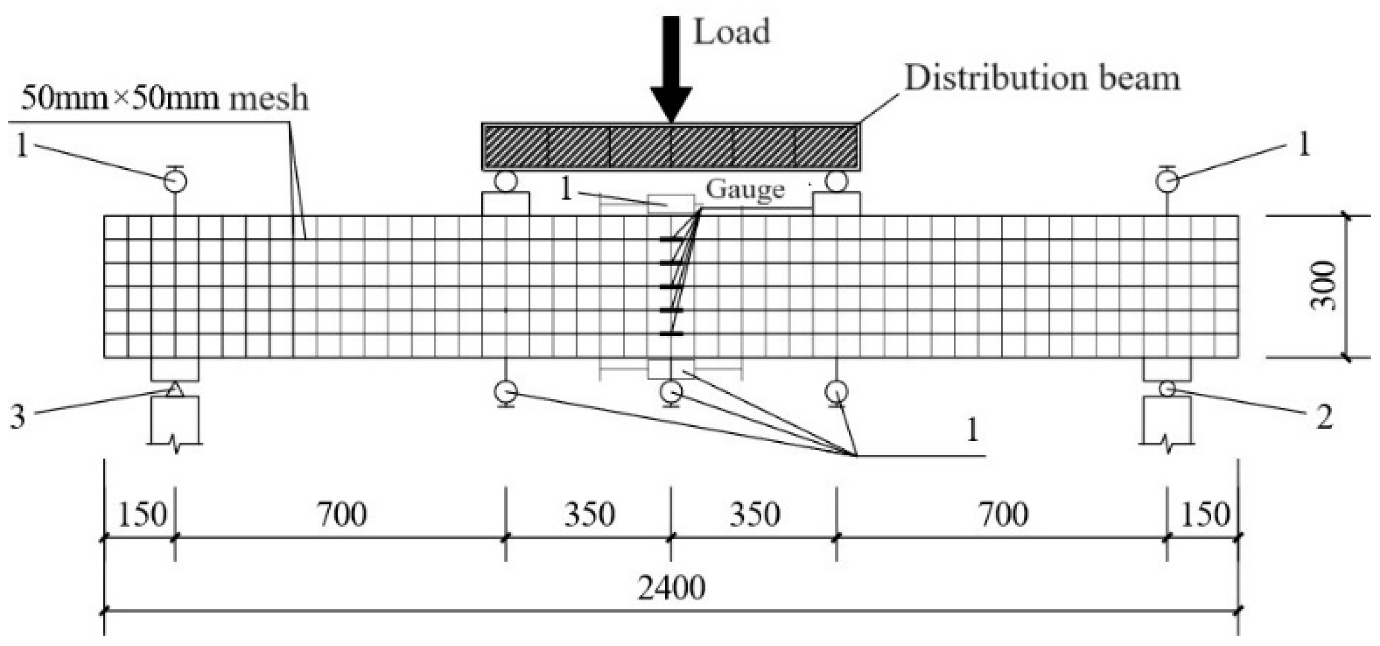
2.3. Test Setup and Instrument

Figure 4 shows the test setup and the instrument arrangement used in this test. A two-point concentrated force loading method was adopted to ensure that only the moment action was present in the midspan of the beam. The vertical pressure was provided by a 5000 kN pressure testing machine. The test load was collected by the pressure sensor of the testing machine itself.
Preloading was carried out before the loading to ensure that the test instrument was in good contact with the specimens and that the instruments and equipment could work normally. The initial loading of the test was load control until 30 kN, the loading rate was 0.2 kN/s, the load increment of each level was 2 kN, and the intermediate load holding time was 300 s. The test was then changed to displacement control. The displacement increment of each level was 2 mm, and the intermediate load holding time was 600 s. The displacement at each stage was changed to 5 mm until the loading displacement reached 30 mm, and the load was held for 600 s. The test was stopped when the displacement reached 55 mm.
One displacement sensor was arranged at the top and bottom of the beam along the beam’s length to monitor the beam section’s rotation. Three displacement sensors were arranged at the middle of the beam span and the loading point position to monitor the vertical displacement. Strain gauges were arranged along the beam height direction to monitor the ECC or concrete strain. The longitudinal and transverse reinforcement strain was monitored through gauges on the reinforcement bars in the beam.

3. Results and Analysis

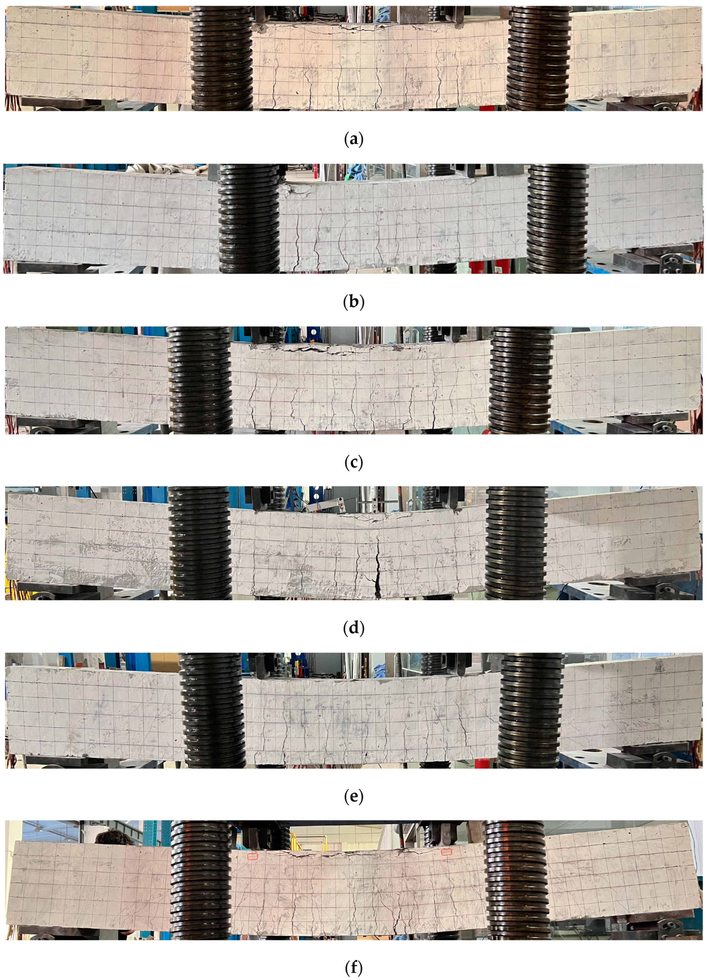
3.1. Failure Description

In Figure 5, the last failure states of each specimen at a deflection of 55 mm are presented. Figure 6 presents the crack distributions of the specimens when the deflection reached 55 mm.
The specimen PSMCB-6 had a common concrete prefabricated shell. When the specimen PSMCB-6 was loaded to 28.0 kN, in the midspan of the beam, several cracks appeared in the tension region. When loaded to 83.8 kN, one longitudinal reinforcement bar yielded in the tension region. The cracks in the bending area continued to develop as the load increased. A crack in the bending section began to develop when the load was 166.0 kN; the crack width was 0.44 mm, and its length was 205.87 mm. The maximum crack width in the bending region in the middle span of the specimen reached 9.0 mm when the test stopped. The final failure mode and crack distribution are shown in Figure 5f and Figure 6f.
For specimen PSMCB-1, the prefabricated shell was made of ECC material. Microcracks appeared at a load of 18.0 kN in the lower parts of the beam. The number of microcracks in the specimen gradually increased with increasing load. The longitudinal reinforcement in the prefabricated shell in the tension region of the beam reached its yield at a load of 114.2 kN. When the load reached 209 kN, cracks began to develop, and the measured crack width was 0.1 mm. The crack width reached 4.1 mm when the test stopped. The ECC composite beam showed better integrity. The final failure pattern and crack distribution are shown in Figure 5a and Figure 6a.
Specimen PSMCB-2 and specimen PSMCB-3 had a different longitudinal reinforcement ratio in the lower part of the beam as compared to PSMCB-1. For specimen PSMCB-2, the failure mode and crack distribution are shown in Figure 5b and Figure 6b. Microcracks appeared for the first time in the tensile region of the beam at a load of about 18.0 kN. When the load was 110.2 kN, the reinforcement bars in the tension region of the beam yielded. Cracks began to develop when the load was 197.4 kN, and the measured crack width was 0.1 mm. When the test stopped, the crack width in the bending section reached 9.0 mm. For specimen PSMCB-3, microcracks were observed when the load was 16.0 kN. The reinforcement bars yielded when the load was 127.5 kN. When the test load was 224.0 kN, the crack width expanded to about 0.2 mm. When the test stopped, the crack width was up to 3.8 mm. The specimen’s failure mode and crack distribution are shown in Figure 5c and Figure 6c.
For specimen PSMCB-4, the longitudinal reinforcement bars in the prefabricated shell differed from those of the composite beam PSMCB-1. Microcracks appeared at a load of 16.0 kN. When the load was 97.5 kN, the reinforcement bars yielded for the first time in the tensile region of the beam. When loaded to 192.0 kN, a crack in the tension region began to develop, with a crack width of about 0.2 mm. At last, the maximum width of the crack reached above 13 mm. The failure mode and crack distribution are shown in Figure 5d and Figure 6d.
The specimen PSMCB-5 was used to study the beam’s mechanical performance when subjected to a negative bending moment. When loaded to 18.0 kN, the first crack appeared in the tension region. When the load was 133.8 kN, the reinforcement bars in the tension region began to yield. When the test stopped, the crack width measured in the bending part extended to a maximum of about 5 mm. The specimen showed good bearing capacity and deformability. The failure mode and crack distribution are shown in Figure 5e and Figure 6e.
Unlike with the RC prefabricated shell composite beam, there was no local fracture at the bottom of the ECC prefabricated shell beam; instead, many very dense microcracks appeared. The load corresponding to the longitudinal bars yielding in the ECC prefabricated shell composite beam was larger than that for the RC composite beam. The load corresponding to crack width expansion in the ECC prefabricated shell composite beam was also higher. Using ECC material in the prefabricated shell of composite beams could improve their deformability and damage resistance.

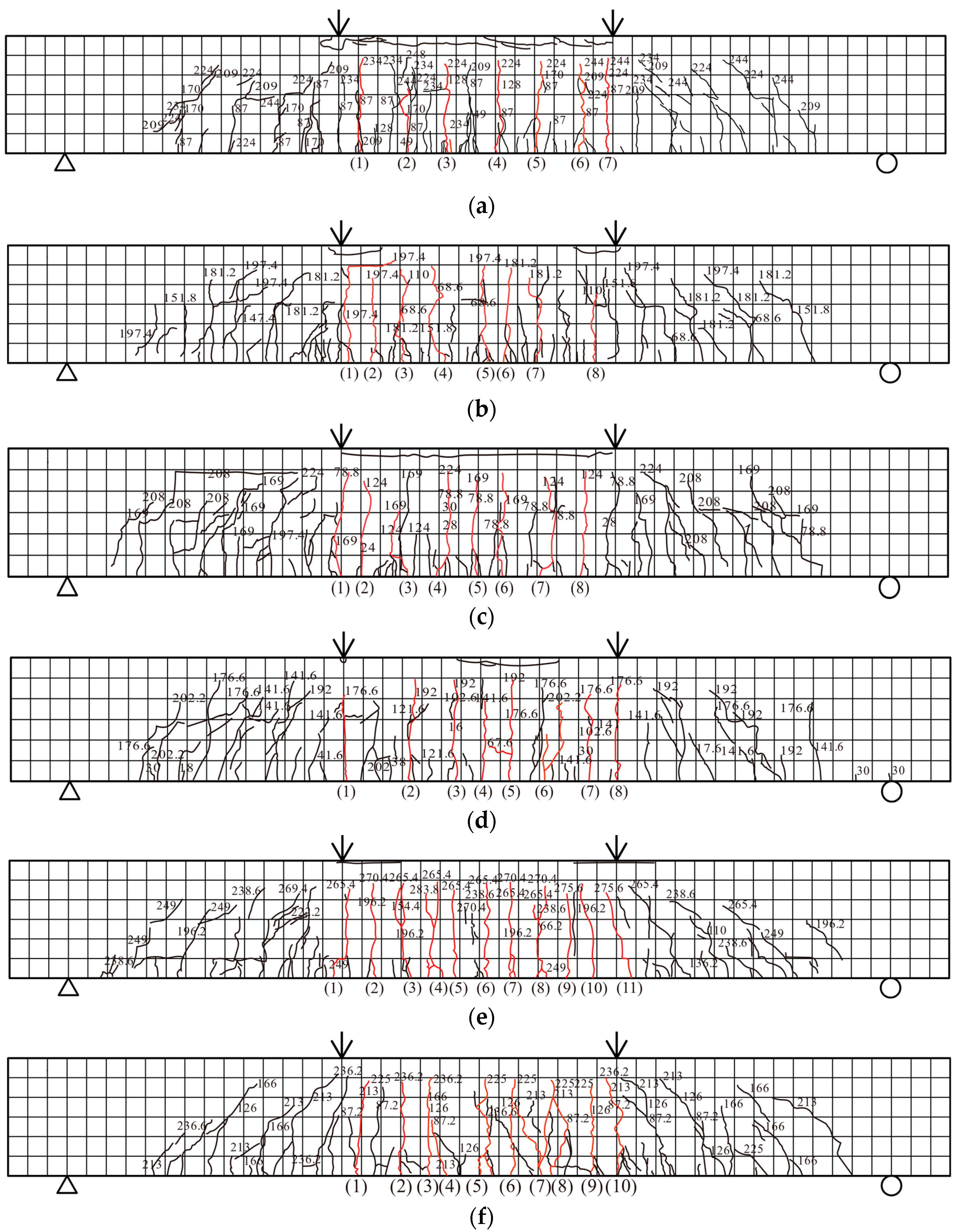
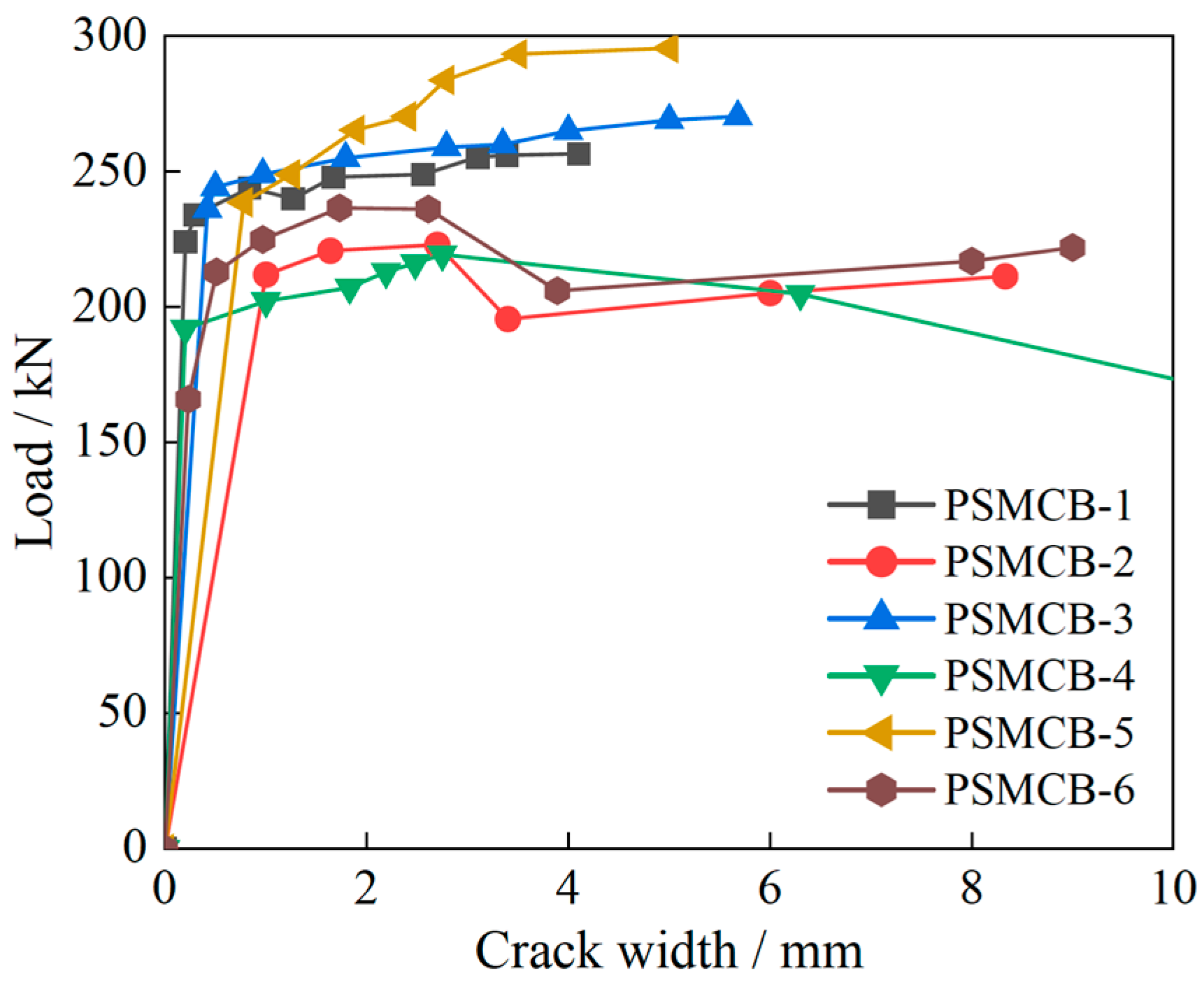
3.2. Crack Width Analysis

According to the values measured by the crack width detector during the test, the curves of the maximum crack width relative to the load were plotted, as shown in Figure 7.
  • In the process of testing the RC composite beam (PSMCB-6), after the first appearance of cracks, the original cracks extended and developed rapidly, although there were still new cracks. Few new cracks appeared after the beam yielded. The crack width expanded rapidly until the concrete at the top of the composite beam was crushed and damaged. However, the ECC composite beam specimen (PSMCB-1) was different. With increasing load, microcracks continued to appear during the test. Even after the composite beam yielded, new cracks continued to appear steadily. The crack width grew relatively slowly until the appearance of the main crack. For the RC composite beam (PSMCB-6), the crack width developed when the load was 166.0 kN. For the ECC prefabricated composite beam (PSMCB-1), cracks began to develop when the load was 209.0 kN. The ECC composite beams exhibited a better crack control capacity. This is mainly due to the characteristics of the ECC material, with microcracking and pseudo-strain hardening. The difference in the tensile hardening characteristics of ECC lies in the designed effect of fiber bridging on its load bearing capacity and energy absorption capacity. After cracking in ECC materials, unlike with the brittle cracking of concrete and other materials, the ECC does not lose its strength and has good crack width control.
  • For the ECC composite beams PSMCB-4, PSMCB-2, PSMCB-1, and PSMCB-3, the reinforcement ratios were 1.07%, 1.13%, 1.21%, and 1.36%, respectively. The corresponding loads at which the cracks began to develop were 192 kN, 197.4 kN, 209 kN, and 224 kN, respectively. When the test stopped, the maximum crack widths were 13 mm, 9.0 mm, 4.1 mm, and 3.8 mm, respectively. Under the same load, the crack width decreased sequentially.

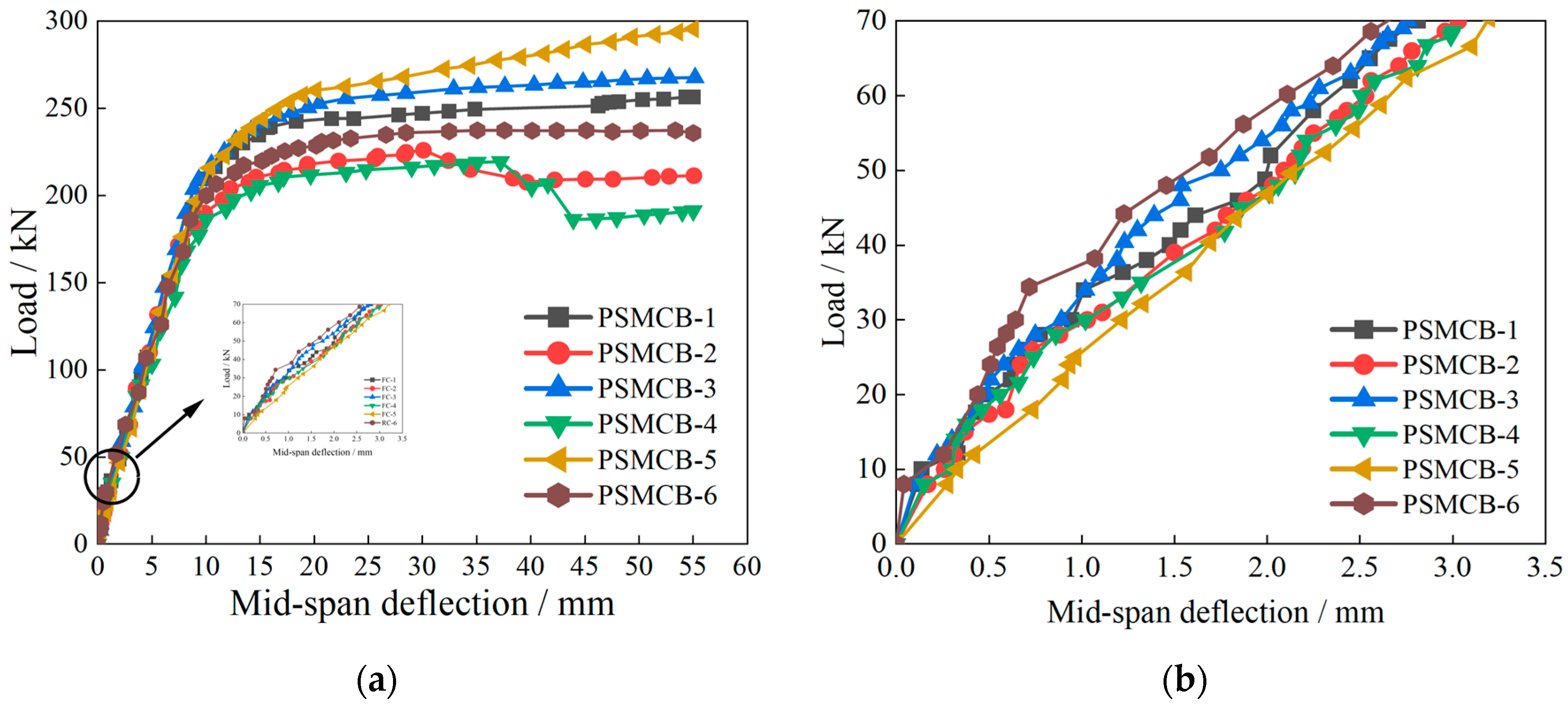
3.3. Bearing Capacity and Deformability

Curves of the load versus mid-span deflection are shown in Figure 8. All specimens experienced the following stress stages.
  • Before cracking, the specimens were in an elastic stage. The load–deflection curves showed a linear change with an increase in load. The initial stiffness of specimen PSMCB-6 was larger than those of specimens PSMCB-1~PSMCB-5. When cracks appeared, the stiffness of the specimens decreased. There was no obvious turning point in the curves of the ECC prefabricated shell composite beams. However, there was a noticeable reduction in the stiffness of specimen PSMCB-6. The stiffness of specimen PSMCB-1 gradually became greater than that of specimen PSMCB-6 when the mid-span displacement reached 2.6 mm. The differences between the curves of ECC composite beams (PSMCB-1, PSMCB-2, PSMCB-3, PSMCB-4) with different longitudinal reinforcement ratios were small.
    Figure 8. Load–deflection curves of composite beams: (a) load–deflection curve; (b) elastic segment curves.
    Figure 8. Load–deflection curves of composite beams: (a) load–deflection curve; (b) elastic segment curves.
    Buildings 14 01024 g008
  • The beams were in the plastic failure stage when the reinforcement bars yielded. Most of the concrete withdrew from the work. The deformation increased rapidly after yielding. The slope of the curves gradually decreased and tended to be horizontal. The stiffness of the composite beams also gradually reduced. The curve slope of specimen PSMCB-1 was still greater than that of specimen PSMCB-6. Thus, the stiffness of the ECC composite beam (PSMCB-1) was also larger than that of the RC composite beam (PSMCB-6), and the stiffness gap gradually increased. For the specimens with different reinforcement ratios, the higher the reinforcement ratio, the slower the specimen’s stiffness decreased.
  • After the reinforcement bars yielded, the loads were not greatly increased. The displacement constantly increased, and the neutralization axis was constantly moving upward. The stiffness decrease for specimen PSMCB-1 was smaller than that for specimen PSMCB-6.
Compared with those of the RC prefabricated shell composite beam (PSMCB-6), the yielding load and bearing capacity of specimen PSMCB-1, with an ECC prefabricated shell, were larger, and the mid-span displacement of specimen PSMCB-1 was less under the same load. As listed in Table 4, comparing the different materials used in the prefabricated shells, the yield load of specimen PSMCB-1 was 5.6% larger than that of specimen PSMCB-6, and the corresponding displacement was slightly larger, with a 0.08 mm difference. The peak load of specimen PSMCB-6 was 237.4 kN, with a corresponding deformation of 53.35 mm, then the load of specimen PSMCB-6 decreased. The peak load of specimen PSMCB-1 was 256.6 kN, with a corresponding deformation of 55 mm; the peak load increased by 8.1% compared with that of specimen PSMCB-6. The load of specimen PSMCB-6 showed an obvious decrease after a displacement of 53.35 mm. In comparison, there was no load decrease for specimen PSMCB-1 when the test stopped. This was mainly due to the contribution of the ECC material, with characteristics of microcracking and pseudo-strain hardening. The difference in the pseudo-strain hardening characteristics of ECC lies in the designed effect of fiber bridging on the load bearing capacity and energy absorption capacity. After cracking of the ECC materials, unlike with the brittle cracking of concrete, the ECC did not lose its strength.
For specimens PSMCB-1 ~ PSMCB-4, the longitudinal reinforcement ratio of specimen PSMCB-2 was 0.08% lower than that of beam PSMCB-1, and the yield load and peak load of beam PSMCB-2 decreased by 20.4% and 13.5% compared with those of beam PSMCB-1. The longitudinal reinforcement ratio of specimen PSMCB-3 was 0.15% higher than that of specimen PSMCB-1. The yield load of specimen PSMCB-3 increased by 6.5%, and the peak load of specimen PSMCB-3 increased by 13.5% compared with that of specimen PSMCB-1. The longitudinal reinforcement ratio of beam PSMCB-4 was 0.14% smaller than that of the composite beam PSMCB-1. The yield load and peak load of specimen PSMCB-4 were 18.5% and 14.5% lower than those of beam PSMCB-1.

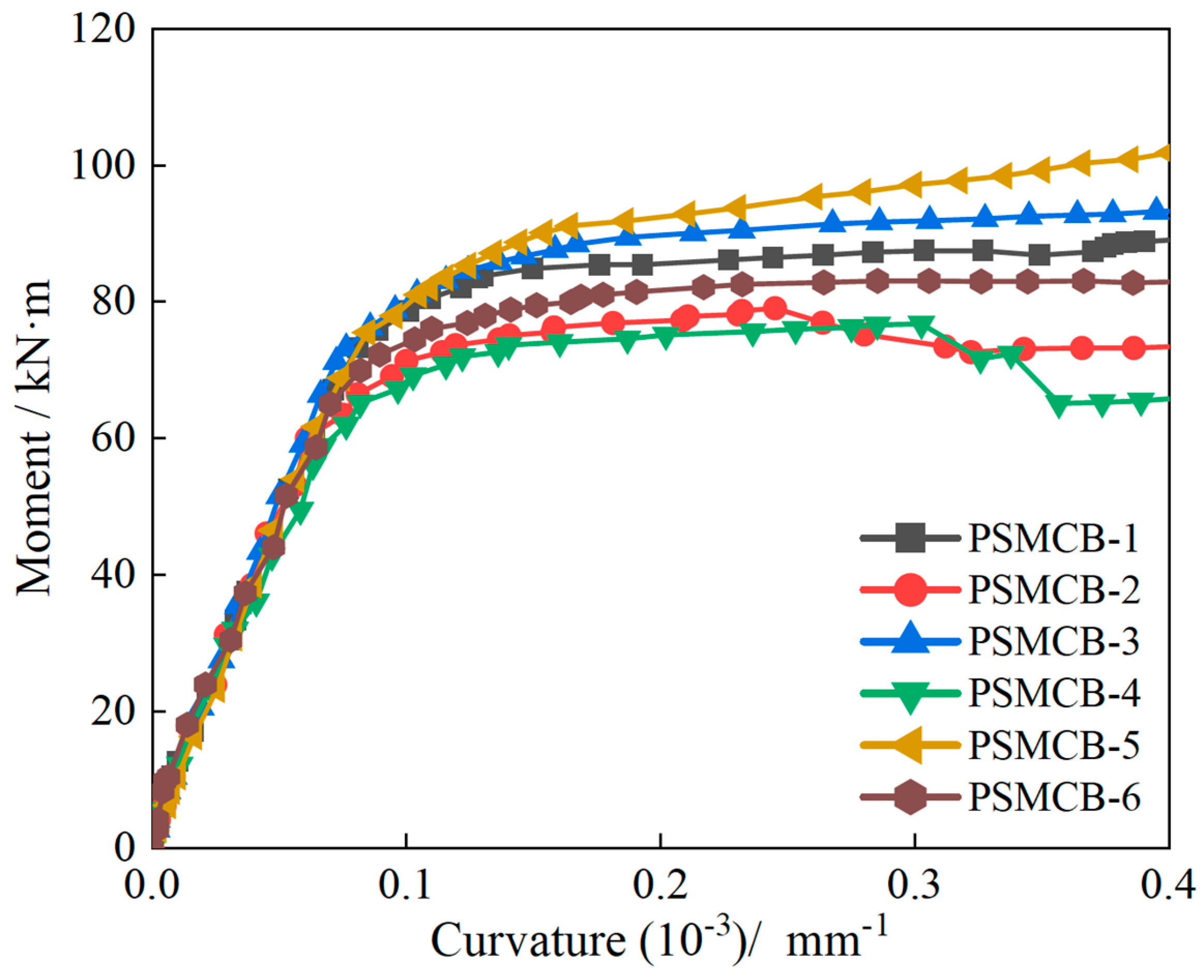
3.4. Moment–Curvature Analysis

Figure 9 shows the moment–curvature curves for the specimens. The overall trend is similar to that of the force–displacement curves. Before cracks appeared, the bending moment was linearly related to the curvature. When cracks appeared, the bending moment was no longer linear with the curvature. The cross−sectional curvature and the deflection increased rapidly. Under the same bending moment, the curvature of the ECC composite beam PSMCB-1 was relatively small among the two composite beams PSMCB-1 and PSMCB-6. When the curvature of specimens PSMCB-1 and PSMCB-6 was 0.0001, the corresponding moments of the specimens were 78.7 kN and 72.3 kN. The bending moment value of specimen PSMCB-1 was relatively higher. There was also no load decrease for specimen PSMCB-1 when the test stopped. In comparison, the moment of beam PSMCB-6 showed a decreasing trend.

3.5. Reinforcement Strain Analysis

According to the measured data from the strain gauges on the longitudinal reinforcements, load–reinforcement strain curves for the six composite beams are plotted in Figure 10. The strain of each composite beam increased steadily during the test.
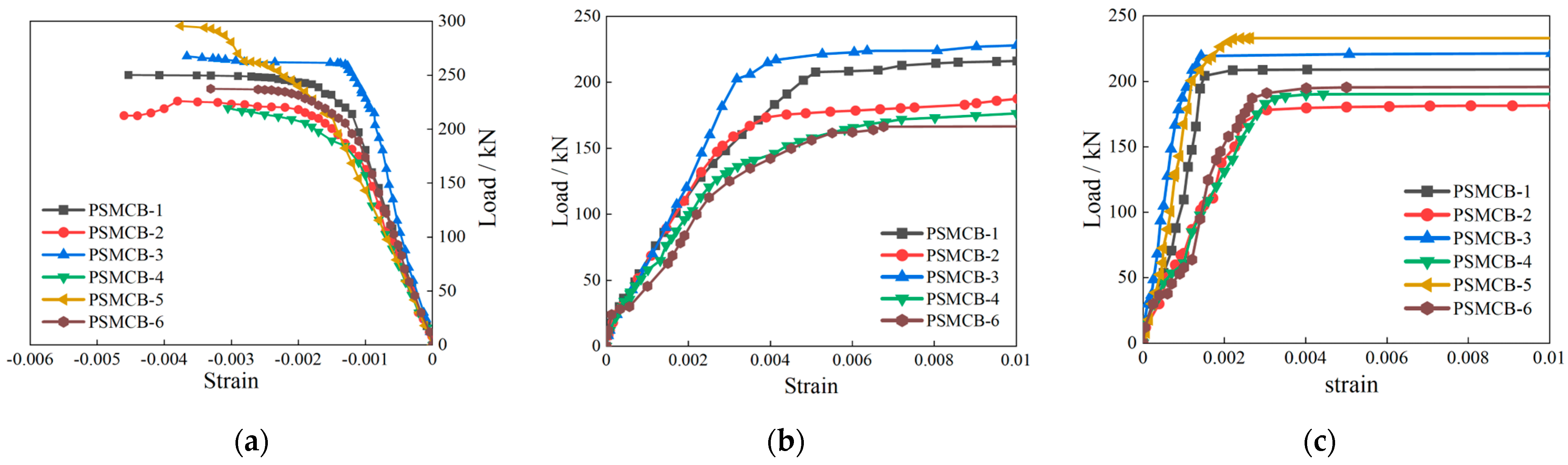
  • For specimens PSMCB-1 and PSMCB-6, with different materials in their prefabricated shells, the reinforcement strain was small in the early stage, and the composite beams’ load–reinforcement strain curves were almost the same. For the RC composite beam (PSMCB-6), when the cracks appeared, the concrete in the crack section directly withdrew from the work, and the reinforcement stress increased suddenly. Thus, there was a sharp increase in the reinforcement strain. For specimen PSMCB-1, the reinforcement bar strain continued to grow without abrupt changes due to the presence of the ECC material. Compared with that of specimen PSMCB-6, the curve slope of the ECC composite beam PSMCB-1 was relatively larger, and the bending bearing capacity was also higher. The load–reinforcement strain curve tended to be smoother more slowly. Under the same load level, the reinforcement strain of specimen PSMCB-1 was relatively smaller among the two composite beams PSMCB-1 and PSMCB-6. In Figure 10b, when the load reached 83.8 kN, the reinforcement bar strain in the prefabricated shell of specimen PSMCB-6 was about 0.002, which was close to yielding, while the strain of specimen PSMCB-1 was only 0.0013. When the reinforcement bar strain of specimen PSMCB-1 reached 0.002, the corresponding load was 114.2 kN. In Figure 10c, when the load reached 146.2 kN, the reinforcement bar strain in the post-poured concrete of specimen PSMCB-6 was about 0.002, while the strain of specimen PSMCB-1 was about 0.0012. When the reinforcement bar strain of specimen PSMCB-1 reached 0.002, the corresponding load reached 207.3 kN. For the reinforcement bars under compression, as shown in Figure 10a, when the reinforcement bar strain reached −0.002, the corresponding load of PSMCB-1 was 243.6 kN, and the corresponding load of PSMCB-6 was 228.4 kN. In Figure 10b, the curves of the reinforcement bars in the prefabricated shells of specimens PSMCB-4 and PSMCB-6 were similar, although the amount of reinforcement in the beam PSMCB-4 was less than that in the beam PSMCB-6. This was mainly because the ECC material underwent multi-crack steady-state propagation under direct tension, showing tensile hardening characteristics. Using ECC material in the prefabricated shell could effectively delay not only the yielding of the longitudinal reinforcement bars but also the yielding of the reinforcement bars in the post-poured concrete. The overall mechanical performance of the beam was improved.
  • For the ECC composite beams (PSMCB-1, PSMCB-2, PSMCB-3, PSMCB-4) with different longitudinal reinforcement ratios, the difference in the reinforcement strain curves of each test beam was very small in the elastic stage. Before the reinforcement bars yielded, as the reinforcement ratio of the longitudinal reinforcement bars increased, the slope of the load versus longitudinal reinforcement bar strain curves for the ECC composite beams was larger under the same load. Correspondingly, the strain on the reinforcement was smaller. In Figure 10c, when the load reached 137.8 kN, the reinforcement bar strain of specimen PSMCB-2 reached 0.002. At the same time, the reinforcement bar strain values of PSMCB-1 and PSMCB-3 were 0.0011 and 0.0006, respectively. When the reinforcement bar strain of PSMCB-1 and PSMCB-3 was 0.002, the load of the two composite beams reached about 207.3 kN and 219.5 kN. When the longitudinal reinforcement yielded, the longitudinal reinforcement bar strain of the composite beams with a lower reinforcement ratio increased dramatically.
  • For the ECC composite beam PSMCB-5, there was no obvious difference as compared to the load–strain curves of the other beams in the early stage. When cracks appeared in the specimen, the reinforcement strain gradually increased since the concrete in the crack section no longer worked with the reinforcement bars. Then, the slope of the reinforcement bar strain curve for specimen PSMCB-5 decreased. When the reinforcement in the tension region yielded, the curve slope of specimen PSMCB-5 was slightly larger. When cracks appeared, due to the fiber bridging in the tension region, the neutralization position was lower under the same level load, and the compression height of the section increased.

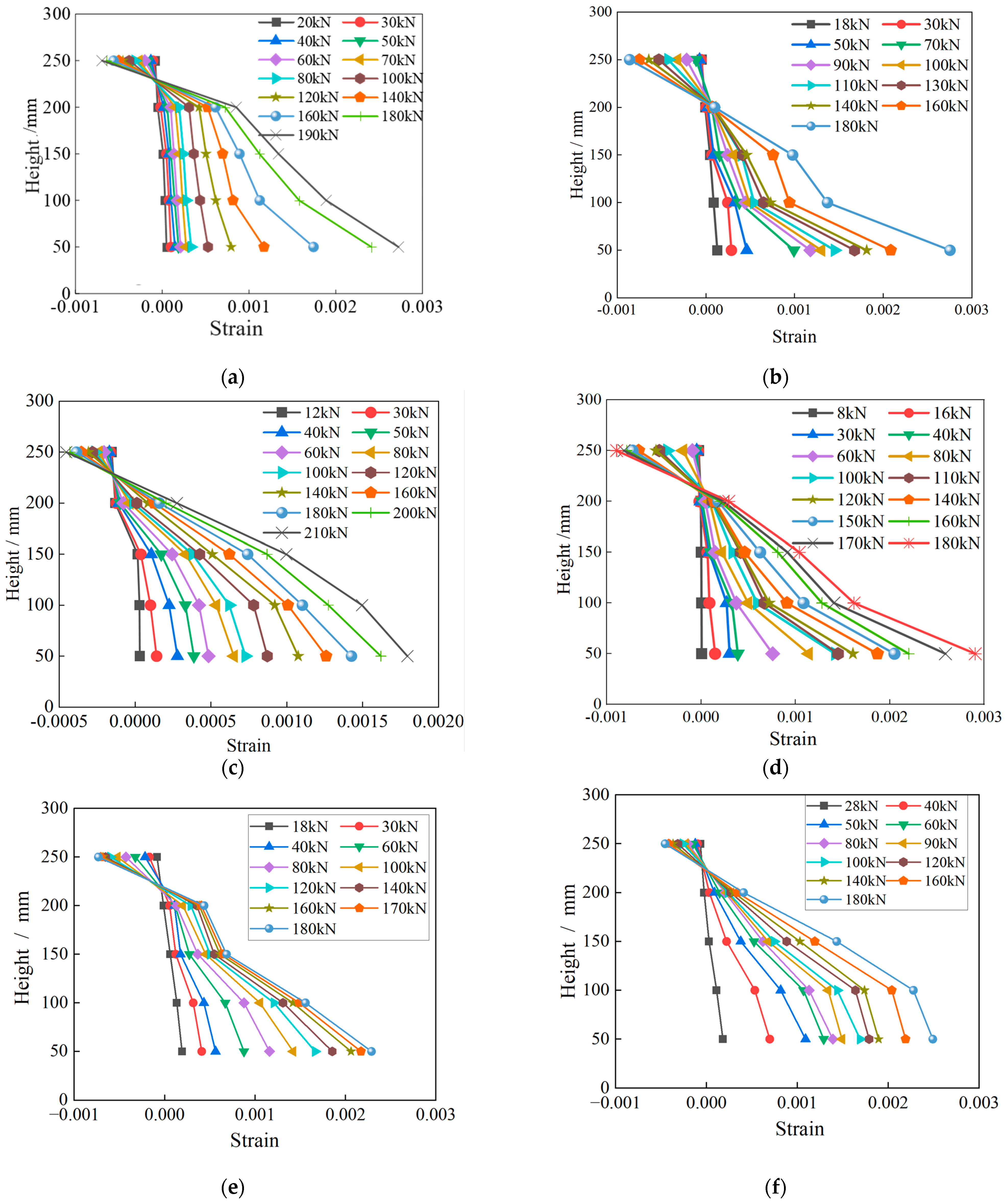
3.6. Plane Section Assumption

When an RC beam is bent, it is assumed that the strain along the length of the beam is approximately linearly distributed along the height direction, i.e., the plane section assumption. Establishing the plane section assumption is a basic precondition for the theoretical analysis of beams. Therefore, it is significant to analyze the plane section assumption to study the mechanical behavior of ECC prefabricated shell monolithic composite beams.
Five concrete strain gauges were arranged along the beam height (h = 300 mm) on the side of the precast monolithic composite beams, and strain gauges were arranged 50, 100, 150, 200, and 250 mm from the bottom of the beam. The ECC material and concrete strain values measured through the five strain gauges under different loads are shown in Figure 11. As the load increased, the values measured by some of the concrete strain gauges deviated, as shown in the figure. The generation of cracks caused the strain values measured at the cracks to suddenly change and no longer showed linear changes. However, on the whole, the average longitudinal strains at each point of the beam section were approximately linear along the height direction. Thus, the beams could be considered to conform to the plane section assumption.
Compared with that of specimen PSMCB-6, the strain of specimen PSMCB-1 with an ECC prefabricated shell was smaller when the two beams were under the same load. For the composite beams with different reinforcement ratios, the strain values were relatively smaller as the ratio increased.

4. Conclusions

Six precast monolithic composite beams were tested to study their flexural behavior. Their flexural failure mode, failure mechanism, bearing capacity, and deformation capacity were studied through flexural performance testing. The following research results were obtained:
  • Compared with the RC prefabricated shell composite beam, specimen PSMCB-1 with an ECC prefabricated shell showed a higher bearing capacity and lower damage degree. The yield load of specimen PSMCB-1 increased by 5.6%, and the corresponding deflection was 0.08 mm larger than that of the beam PSMCB-6. The ultimate load increased by 8.1%. When the tests stopped, the maximum crack width of specimen PSMCB-1 was 4.1 mm, while the maximum crack width of specimen PSMCB-6 reached 9.0 mm.
  • For composite beams, an ECC prefabricated shell could effectively delay the yielding of longitudinal reinforcement. Under the same load, the reinforcement strain of specimen PSMCB-1 with an ECC prefabricated shell was smaller than that of the RC composite beam PSMCB-6. The load of the ECC composite beam was significantly higher than that of RC composite beam when the reinforcement bars were under the same strain.
  • The ECC precast monolithic composite beams showed good bearing capacity, integrity, and deformability. Compared with those of specimen PSMCB-1, the longitudinal reinforcement ratio of beam PSMCB-2 was 0.08% lower, the yield load was reduced by 20.4%, and the ultimate load was reduced by 13.5%. The longitudinal reinforcement ratio of beam PSMCB-3 was 0.15% higher than that of beam PSMCB-1; the yield load of specimen PSMCB-3 increased by 6.5%, and the ultimate load increased by 13.5%. Until the end of loading, the bearing capacity of specimens PSMCB-1 and PSMCB-3 did not decrease.

Author Contributions

Conceptualization, T.L. and K.G.; investigation, Z.L. and K.G.; data curation, Z.L. and K.G.; writing—original draft preparation, T.L. and Z.L.; writing—review and editing, T.L. and J.P.; supervision, T.L.; funding acquisition, T.L. and J.P. All authors have read and agreed to the published version of the manuscript.

Funding

This research was funded by the Natural Science Foundation of Shaanxi Province, grant numbers “2021JQ-873” and “2022JQ-557”, and the Youth Innovation Team of Shaanxi Provincial Department of Education, grant number 21JP140.

Data Availability Statement

The data that support this study are available from the corresponding author upon reasonable request.

Acknowledgments

The authors express their gratitude to those who provided the equipment and technical support for the testing described in this paper.

Conflicts of Interest

The authors declare no conflicts of interest.

References

  1. Lu, T.; Guan, K.; Pan, J.; Liang, X. The effect of ECC materials on seismic performance of beam-column subassemblies with slabs. Buildings 2023, 13, 1942. [Google Scholar] [CrossRef]
  2. Lu, T.; Zhou, H.; Liang, X.W. Research on the mechanical properties of the joint of the beam-column subassembly. Structures 2022, 35, 873–881. [Google Scholar] [CrossRef]
  3. Zhang, X.; Liu, G.; Shen, Z.; Gao, Y.; Zhou, H.; Wang, Z. A comprehensive study on the effect of reinforcing methods on the flexural behavior of Concrete-RUHTCC composite beams. Eng. Struct. 2023, 292, 116524. [Google Scholar] [CrossRef]
  4. Al-Osta, M.A.; Isa, M.N.; Baluch, M.H.; Rahman, M.K. Flexural behavior of reinforced concrete beams strengthened with ultra-high performance fiber reinforced concrete. Constr. Build. Mater. 2017, 134, 279–296. [Google Scholar] [CrossRef]
  5. Bahraq, A.A.; Al-Osta, M.A.; Ahmad, S.; Al-Zahrani, M.M.; Al-Dulaijan, S.O.; Kalimur Rahman, M. Experimental and numerical investigation of shear behavior of RC beams strengthened by ultra-high performance concrete. Int. J. Concr. Struct. Mater. 2019, 13, 6. [Google Scholar] [CrossRef]
  6. Zhang, X.F.; Xu, S.L.; Li, H.D. Theoretical analysis of flexural performance of plain concrete composite beams strengthened with ultrahigh toughness cementitious composite. China Civ. Eng. J. 2010, 43, 51–62. [Google Scholar] [CrossRef]
  7. Xu, S.L.; Wang, N.; Li, Q.H. Experimental study on the flexural performance of concrete beam strengthened with ultra high toughness cementitious composites. China Civ. Eng. J. 2010, 43, 17–22. [Google Scholar] [CrossRef]
  8. Zhang, Y.; Yang, Z.; Xie, T.; Yang, J. Flexural behavior and cost effectiveness of layered UHPC-NC composite beams. Eng. Struct. 2022, 273, 115060. [Google Scholar] [CrossRef]
  9. Nguyen, D.-L.; Thai, D.-K.; Nguyen, H.T.T.; Nguyen, T.-Q.; Le-Trung, K. Responses of composite beams with high-performance fiber-reinforced concrete. Constr. Build. Mater. 2021, 270, 121814. [Google Scholar] [CrossRef]
  10. Liang, X.W.; Wang, P.; Xu, M.X. Flexural behavior and capacity analysis of RC beams with permanent UHPC formwork. Eng. Mech. 2019, 36, 95–107. [Google Scholar] [CrossRef]
  11. Wang, Z.; Liang, X.; Wang, Y.; Zhai, T. Experimental and theoretical investigations on the flexural behavior of RC slabs with steel-PVA hybrid fiber reinforced cementitious composite (HFRCC) permanent formwork. Case Stud. Constr. Mater. 2022, 17, e01432. [Google Scholar] [CrossRef]
  12. Qin, F.; Wei, X.; Lu, Y.; Zhang, Z.; Di, J.; Yin, Z. Flexural behaviour of high strength engineered cementitious composites (ECC)-reinforced concrete composite beams. Case Stud. Constr. Mater. 2023, 18, e02002. [Google Scholar] [CrossRef]
  13. Qiao, Z.; Pan, Z.; Xue, W.; Meng, S. Experimental study on flexural behavior of ECC/RC composite beams with U-shaped ECC permanent formwork. Front. Struct. Civ. Eng. 2019, 13, 1271–1287. [Google Scholar] [CrossRef]
  14. Zhang, R.; Hu, P.; Zheng, X.; Cai, L.; Guo, R.; Wei, D. Shear behavior of RC slender beams without stirrups by using precast U-shaped ECC permanent formwork. Constr. Build. Mater. 2020, 260, 120430. [Google Scholar] [CrossRef]
  15. Zhang, P.; Xu, F.; Liu, Y.; Sheikh, S.A. Shear behaviour of composite beams with permanent UHPC formwork and high-strength steel rebar. Constr. Build. Mater. 2022, 352, 128951. [Google Scholar] [CrossRef]
  16. Abbas, Y.M.; Khan, M.I. Behavioral response of reinforced concrete beams with ultra-ductile fiber-reinforced cementitious composite layers-Experiments, models and reinforcement limits. J. Build. Eng. 2023, 77, 114004. [Google Scholar] [CrossRef]
  17. Hu, Z.; Zhou, Y.; Hu, B.; Huang, X.; Guo, M. Local use of ECC to simultaneously enhance the shear strength and deformability of RC beams. Constr. Build. Mater. 2022, 353, 129085. [Google Scholar] [CrossRef]
  18. Zanuy, C.; Gonzalo, S.D. Ulzurrun, Manfred Curbach. Experimental determination of sectional forces in impact tests: Application to composite RC-HPFRCC beams. Eng. Struct. 2022, 256, 114004. [Google Scholar] [CrossRef]
Figure 1. Illustration of each composite beam: (a) dimensions of composite beams; (b) PSMCB-1; (c) PSMCB-2; (d) PSMCB-3; (e) PSMCB-4; (f) PSMCB-5; (g) PSMCB-6.
Buildings 14 01024 g001
Figure 2. Diagram of the specimen manufacturing process: (a) shell cross−sectional dimensions; (b) the prefabricated shell.
Buildings 14 01024 g002
Figure 3. Tensile stress−strain diagram of ECC material.
Buildings 14 01024 g003
Figure 4. Diagram of the testing instruments: 1−linear variable displacement transducer; 2−sliding hinge supports; 3−hinge supports.
Buildings 14 01024 g004
Figure 5. Bending failure states of specimens: (a) PSMCB-1; (b) PSMCB-2; (c) PSMCB-3; (d) PSMCB-4; (e) PSMCB-5; (f) PSMCB-6.
Buildings 14 01024 g005
Figure 6. Crack distributions in the specimens: (a) PSMCB-1; (b) PSMCB-2; (c) PSMCB-3; (d) PSMCB-4; (e) PSMCB-5; (f) PSMCB-6.
Buildings 14 01024 g006
Figure 7. Load versus crack width.
Buildings 14 01024 g007
Figure 9. Bending moment−curvature of the cross section.
Buildings 14 01024 g009
Figure 10. Load−reinforcement strain curves: (a) longitudinal reinforcement bars under compression; (b) longitudinal reinforcement in the prefabricated shell; (c) longitudinal reinforcement bars under tension.
Buildings 14 01024 g010
Figure 11. Cross−sectional strain along the beam height: (a) PSMCB-1; (b) PSMCB-2; (c) PSMCB-3; (d) PSMCB-4; (e) PSMCB-5; (f) PSMCB-6.
Buildings 14 01024 g011
Table 1. Parameters of composite beams.
NumberMaterial of the ShellLongitudinal Bars in Shell/HRB400Longitudinal Bars in Post-Cast Concrete/HRB400Longitudinal
Reinforcement
Ratio/%
Stirrups
/HPB300
Lower Upper
PSMCB-1ECC4–103–122–161.216@70
PSMCB-2ECC4–102–142–161.13
PSMCB-3ECC4–102–162–161.36
PSMCB-4ECC4–83–122–161.07
PSMCB-5ECC4–103–123–161.46
PSMCB-6RC4–103–122–161.21
Table 2. Component materials of ECC (kg/m3).
CementFly AshWaterSandFiber
56969640545526
Table 3. Mechanical properties of steel reinforcements.
GradeDiameter (mm)fy (MPa)fu (MPa)Es/GPa
HPB3006355506210
8410512
HRB40010425626200
12465642
14442614
16532698
Table 4. The characteristic load values and deflection of the composite beams.
NumberCracking Load/kNYielding Load/kNYielding Deflection/mmUltimate Load/kN
PSMCB-118.0219.211.30256.6
PSMCB-218.0174.58.27226.0
PSMCB-312.0233.413.14267.6
PSMCB-416.0178.510.62219.4
PSMCB-518.0239.814.34295.6
PSMCB-628.0207.611.22237.4
Disclaimer/Publisher’s Note: The statements, opinions and data contained in all publications are solely those of the individual author(s) and contributor(s) and not of MDPI and/or the editor(s). MDPI and/or the editor(s) disclaim responsibility for any injury to people or property resulting from any ideas, methods, instructions or products referred to in the content.

