Article

Simplified Model Study of Autoclaved Aerated Concrete Masonry Flexible Connection Infilled Frames with Basalt Fiber Grating Strips

1
Key Laboratory of Earthquake Engineering and Engineering Vibration, Institute of Engineering Mechanics, China Earthquake Administration, Harbin 150080, China
2
Key Laboratory of Earthquake Disaster Mitigation, Ministry of Emergency Management, Harbin 150080, China
3
State Key Laboratory of Coastal and Offshore Engineering, Faculty of Infrastructure Engineering, Dalian University of Technology, Dalian 116024, China
*
Author to whom correspondence should be addressed.
Buildings 2024, 14(4), 1033; https://doi.org/10.3390/buildings14041033
Submission received: 29 February 2024 / Revised: 29 March 2024 / Accepted: 5 April 2024 / Published: 8 April 2024
(This article belongs to the Special Issue Research on the Seismic Performance of Reinforced Concrete Structures)

Abstract

:
Infilled walls and frames typically employ closely spaced rigid connection, which, under seismic actions, can lead to adverse effects such as amplified seismic responses, overall torsion, and the formation of weak layers in the structure. Flexible connection isolating the infilled walls from the frames can effectively mitigate the adverse effects of rigid connections. In order to reduce the structural mass and seismic impacts, Autoclaved Aerated Concrete (AAC) masonry flexible connection infilled walls have been widely researched. However, most AAC masonry flexible connection infilled walls require complex process operations for AAC blocks, which is not conducive to practical applications in engineering. Therefore, an AAC flexible connection infilled wall with Basalt Fiber Grating (BFG) strips instead of steel bars, with simplified process operations, has been proposed. Existing finite element models for BFG strip-reinforced AAC masonry flexible connection infilled walls employ solid elements, which are difficult to apply to large-scale structural simulations; moreover, existing simplified models for flexible connection infilled walls cannot simulate out-of-plane loading. In this paper, based on homogenization methods, using simplified elements to simulate components, a simplified model for the BFG strip-reinforced AAC masonry flexible connection infilled frame is proposed. Utilizing this model, stress analyses under both in-plane and out-of-plane loading are conducted and compared with corresponding experimental results. The results indicate that the in-plane simplified model (ISM) fits well with the experimental results in terms of hysteresis curves, with similar relationships between stiffness degradation and strength attenuation. The displacement force curve of the out-of-plane simplified model (OSM) before reaching the peak load is in good agreement with the experimental results. The maximum plastic range of OSM is 5% smaller than the test results, and it can be considered that the plastic ranges of the two are comparable, manifesting the models’ capability to adequately manifest arching behavior. The simplified model enables simulation of out-of-plane loading and provides a new approach for modeling large-scale frame structures with flexible connection infilled wall.

1. Introduction

Earthquakes represent a highly hazardous natural disaster. When a strong earthquake affects buildings, structural damage occurs, which can be categorized into structural damage and non-structural component damage. Usually, in the field of earthquake engineering, seismic research efforts have focused primarily on the main structures. With the recent development of seismic concepts based on performance and resilience, there has been a growing demand for assessing the performance of various functional units within buildings and evaluating seismic losses. This demand reflects the needs of the current economic and social environment. Non-structural components in buildings exhibit characteristics such as diverse types, large quantities [1], and significant investments [2]. Therefore, evaluating the seismic performance of non-structural components has become an important approach to enhancing building resilience and reducing economic losses in construction. In the realm of structural engineering, infilled walls represent a commonly utilized non-structural component [3]. Typically, infilled walls and frames are tightly connected, i.e., rigid connections. Rigid connection can enhance structural stiffness, enabling infilled walls to participate in structural seismic responses [4,5,6]. However, under strong earthquake effects, rigid connections induce detrimental effects on the structure, including amplified seismic responses [7], overall torsion [8], the formation of weak layers [9], and corner shear failures in frame columns [10]. Additionally, it makes the infilled wall experience in-plane shear failure and out-of-plane collapse [11], posing severe threats to life and property safety [12]. To address the issues arising from rigid connections and enable both the frame and the infilled wall to fulfill their respective functions, researchers have introduced flexible connection schemes. The core idea is to isolate the infilled wall from the framework, mitigating shear-induced failure of the wall-frame diagonal bracing within prescribed inter-story drift angle limits. This strategy aims to harness the seismic load-bearing capacity of the infilled wall, enhance the overall structural energy dissipation capacity, and coordinate seismic damage between the infilled wall and the framework while adhering to specified limits on inter-story drift angles. Numerous researchers both domestically and internationally have proposed various flexible connection schemes, undertaking experimental and theoretical studies to explore their efficacy [13,14,15,16,17,18,19,20,21,22,23]. Many countries also recommend or utilize flexible connection schemes in their seismic design codes [24,25,26,27]. Aliaari et al. [28] proposed a framework-infilled wall structure with a sub-frame. The sub-frame is connected to the infilled wall using brittle elements and is rigidly connected to the main frame. This configuration enables coordinated motion of the framework and infilled wall under small seismic events, while allowing the infilled wall to detach from the sub-frame during moderate to large seismic events. Based on isolation principles, Kauffman et al. [29] proposed the concept of a structural fuse in infilled walls made of different materials. The structural fuse is designed to break under high loads, thereby achieving isolation between the infilled wall and the frame. Tasligedik et al. [30,31] proposed a structural system based on the commonly used steel-frame-wallboard system in New Zealand. The introduction of flexibility in the system was achieved by incorporating gaps between the infilled wall and the steel frame. The Autoclaved Aerated Concrete (AAC) block is a type of environmentally friendly infilled wall material that is widely used due to its lightweight, high processability, good thermal efficiency, and excellent fire resistance [32]. In order to reduce the overall structural mass and seismic impacts, some scholars have proposed the AAC masonry flexible connection infilled wall. Erdem et al. [33] designed three different flexible connection schemes for AAC masonry flexible connection infilled wall and conducted experimental and numerical studies. Zhou et al. [34] based on Chinese standards, arranged X-shaped diagonal braces in AAC masonry flexible connection infilled walls to improve the in-plane seismic performance. However, the above-mentioned schemes all require complex processing operations for AAC blocks, which are not conducive to practical application in engineering. In China, both the “Code for Seismic Design of Buildings” [26] and the “Code for Seismic Design of Non-structural Components” [27] stipulate that flexible connections are achieved by separating the infilled wall and the frame by a certain distance and connecting the infilled wall to the frame columns through 6 mm diameter tie bars placed in the block joints. However, the “Technical Code for Masonry Structure of Autoclaved Aerated Concrete Block” [35] in China stipulates that the joint width for AAC masonry should be less than 3 mm. This limitation restricts the application of AAC blocks in flexible connection infilled walls. To address this issue, Xiong et al. [36] proposed the utilization of Basalt Fiber Grating (BFG) strips as a substitute for steel reinforcement in AAC blocks infilled walls and conducted essential mechanical performance experiments on AAC blocks reinforced with BFG strips. Chen [37] proposed two types of flexible connections between walls and frame columns specifically designed for a BFG strip-reinforced AAC masonry flexible connection infilled wall. Experimental investigations on both in-plane and out-of-plane seismic performance were conducted. The study focused on the load-bearing capacity of the infilled wall, its self-destruct characteristics, and its influence on the load-carrying capacity of the frame. In continuation of Chen’s [37] work, Luo [38] proposed two novel flexible connection methods for walls and frame columns by varying the combinations of connectors. Experimental investigations were conducted to analyze the impact of these connection methods on the seismic performance of the BFG strip-reinforced AAC masonry flexible connection infilled wall. Research [37,38,39,40,41] indicates that the BFG strip-reinforced AAC masonry flexible connection infilled wall can meet the requirements of thin joint construction for AAC infilled walls. It exhibits good in-plane flexibility and out-of-plane bearing capacity during earthquakes, enhancing the seismic resilience of infilled walls. The BFG strip-reinforced AAC masonry flexible connection infilled wall approach has promising prospects for wide application.
The seismic resilience of buildings refers to the ability to maintain and restore its original functionality following a specified level of seismic action. The assessment of seismic resilience in buildings is currently one of the most prominent issues in the field of earthquake engineering, with numerous scholars conducting research in this area [42,43,44,45,46,47,48,49]. Many countries [50,51] and organizations [52,53] have also established their own standards for the assessment of seismic resilience in buildings. In China, according to the “Standard for seismic resilience assessment of buildings” [51], it is stipulated that when evaluating the seismic resilience of buildings, it is necessary to establish finite element models of the structure and conduct elastoplastic analyses. The finite element model of infilled walls and frames, from a modeling perspective, can be categorized into discretized models and homogenized models. Discretized models further include fully discretized models and semi-discretized models. From the element selection perspective, it can be divided into solid element models and simplified element models. The fully discretized model involves simulating masonry blocks and mortar layers separately using different elements. The semi-discretized model combines each masonry block with the surrounding 50% thickness of mortar to form a composite block for modeling purposes. The homogenized model treats the masonry blocks and mortar as a continuous and homogeneous entity, employing a single element for modeling. The solid element model is capable of simulating the cracking and failure of masonry blocks, but it entails a high number of elements, complex contact rules, and prolonged computational times. It is commonly employed for modeling small, simple components with stringent accuracy requirements. In contrast, the simplified element model, while offering reduced computational load due to the use of elements with simpler mechanical characteristics, lacks the ability to simulate the cracking and failure of walls. It is suitable for modeling large, complex components where accuracy requirements are less stringent. Numerous scholars have employed finite element methods to investigate flexible connection infilled walls. EI Haddad [54] utilized beam elements and bilinear four-node elements to, respectively, model the frame and infilled walls. The study investigated the influence of wall-frame separation on structural mechanical performance. Liu et al. [55] employed solid elements C3D8R to establish a model for infilled walls and frames, using nonlinear springs to simulate the flexible connection between walls and frames. Zhou et al. [56] utilized beam elements and plane stress elements to establish a flexible connection frame infilled wall model in two-dimensional space, investigating the in-plane structural performance. For the BFG strip-reinforced AAC masonry flexible connection infilled wall, scholars have also conducted finite element studies. Liu [39] constructed a fully discretized model for the BFG strip-reinforced AAC masonry flexible connection infilled wall in Abaqus, simulating the in-plane and out-of-plane force-induced failure processes. Chen [40] investigated the dynamic characteristics of the BFG strip-reinforced AAC masonry flexible connection infilled wall through finite element simulation. Wang [41] employed a multi-element modeling approach to construct a five-story structure model of the BFG strip-reinforced AAC masonry flexible connection infilled wall. Subsequently, a study on the vulnerability of this model was conducted. In seismic resilience research for buildings, it is necessary to establish finite element models for the entire structure. From the aforementioned, it can be inferred that existing finite element studies on the BFG strip-reinforced AAC masonry flexible connection infilled wall have predominantly utilized solid elements to simulate individual components, making it difficult to effectively model large-scale integrated structures and apply them in assessing the seismic resilience of framed structures with BFG strip-reinforced AAC masonry flexible connection infilled walls. Additionally, most existing simplified models for flexible connection infilled wall are primarily capable of simulating in-plane loading, thus facing challenges in modeling the more prevalent out-of-plane loading failures associated with flexible connection infilled walls and assessing the seismic resilience of framed structures with flexible connection infilled walls. These existing models fail to meet the requirements for structural models in seismic resilience assessment of buildings.
In this paper, based on seismic performance experiments conducted on three BFG strip-reinforced AAC masonry flexible connection infilled wall, a three-dimensional simplified model for such infilled frames was established in Abaqus/Standard. The model, based on a homogenized simplification approach, utilized beam elements to simulate the framework, shell elements to simulate the infilled walls, and nonlinear springs to simulate the flexible connectors between the framework and infilled walls. Boundary conditions and loading scenarios were formulated according to the in-plane and out-of-plane experiments conducted during the seismic performance test on the BFG strip-reinforced AAC masonry flexible connection infilled wall. Using this simplified model, finite element simulations of the seismic performance tests were conducted. The computed results were compared and analyzed against the experimental data to validate the effectiveness and rationality of the simplified model. This study provides a new approach for the simplified calculation of the BFG strip-reinforced AAC masonry flexible connection infilled wall within frame structures, contributing to the understanding of the seismic behavior of flexible connection masonry infilled walls.

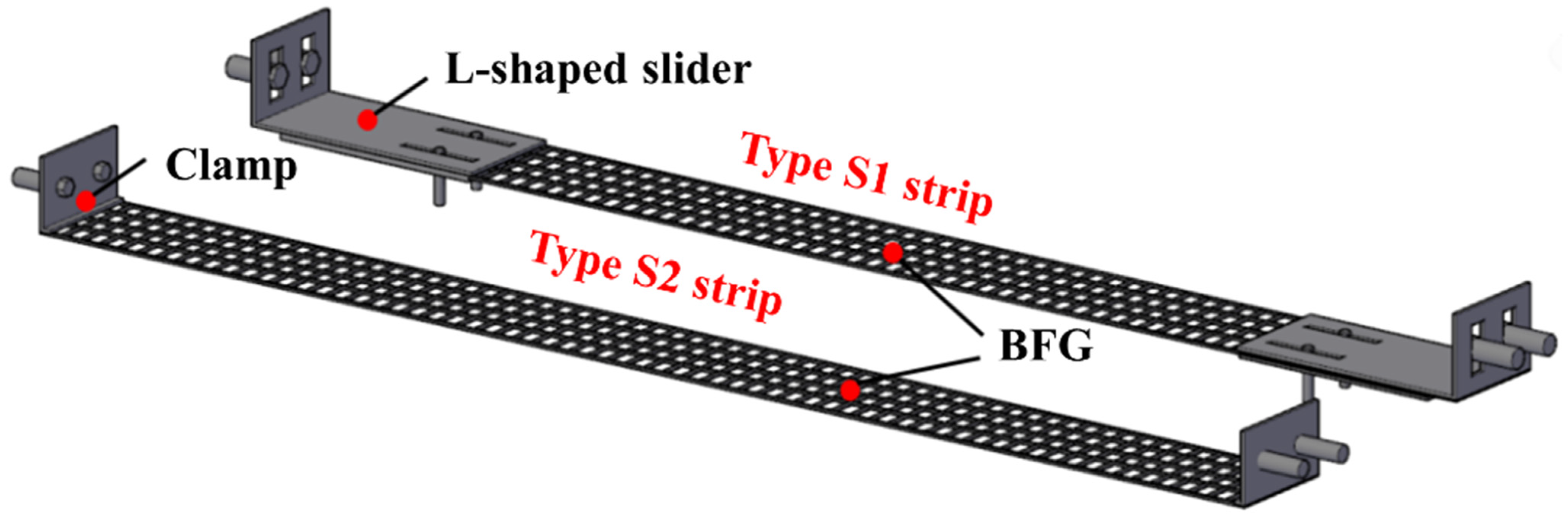
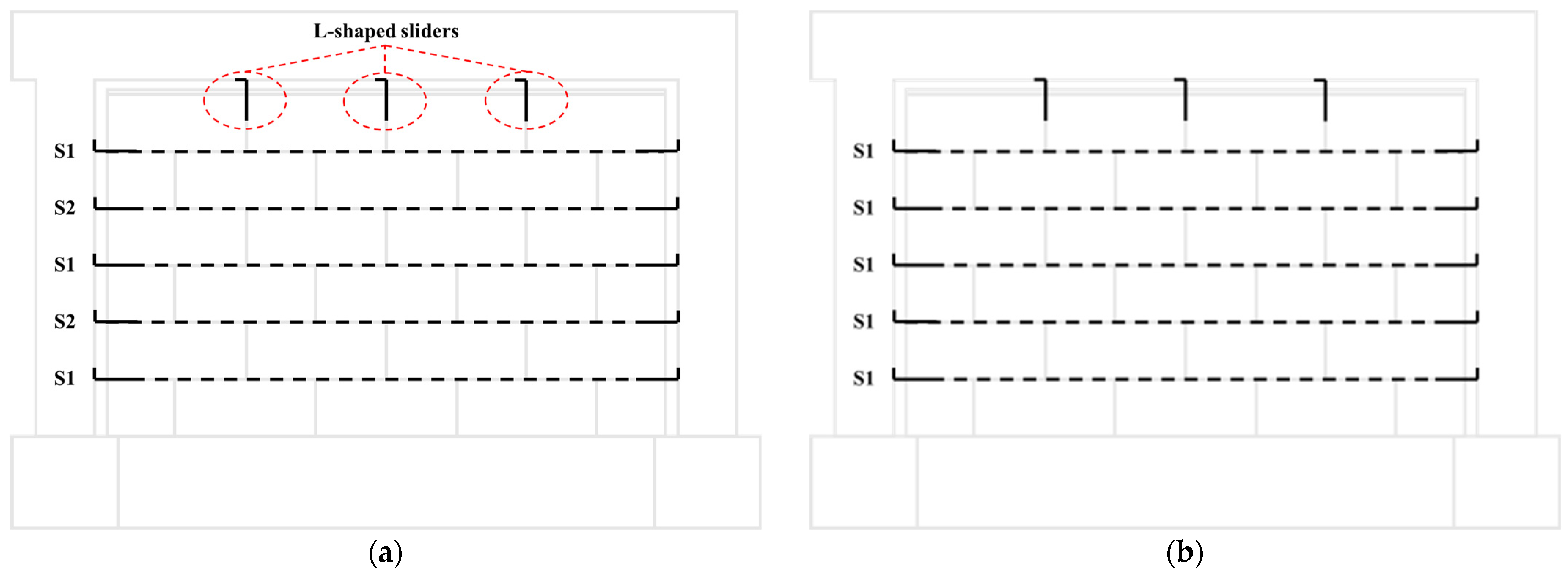
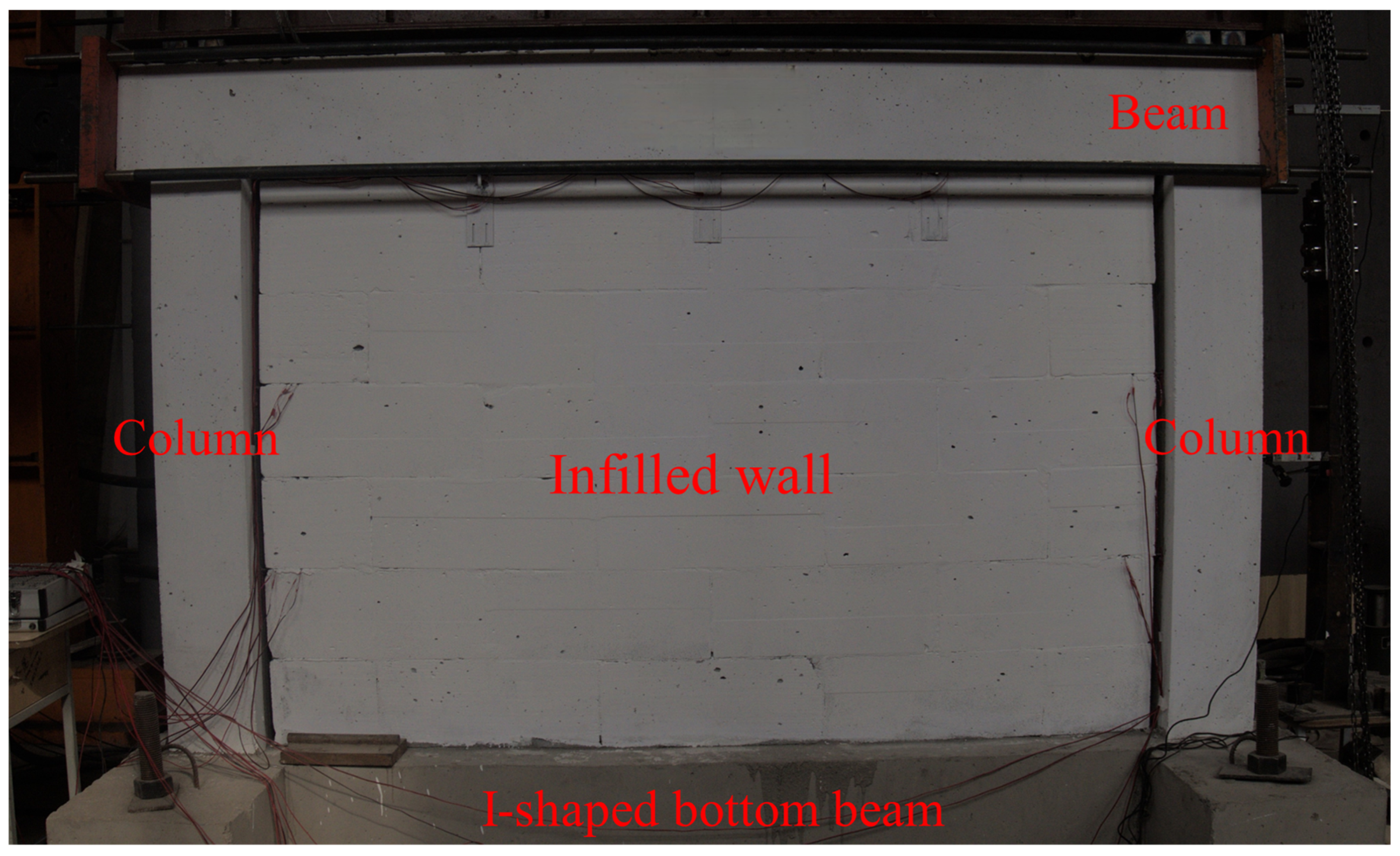
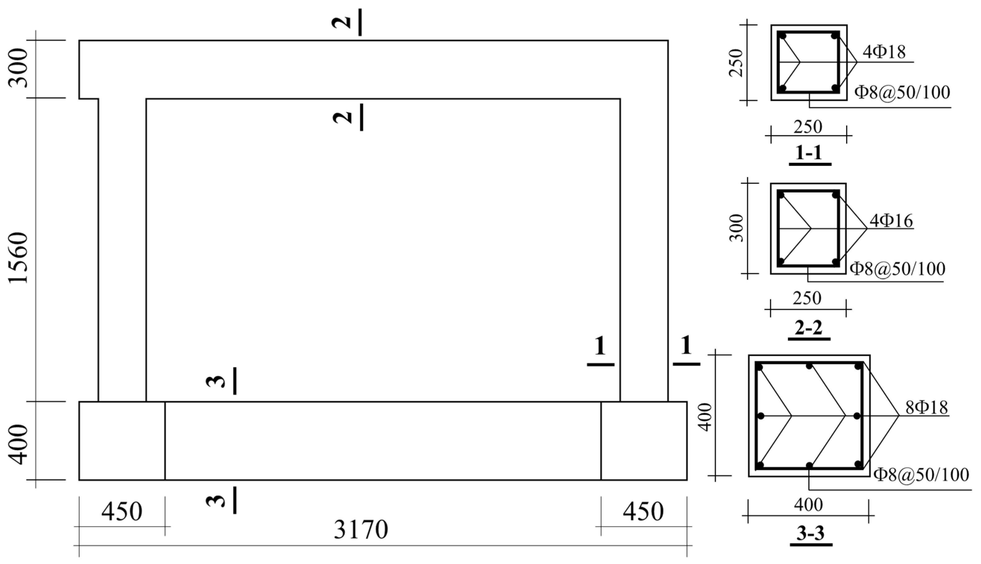
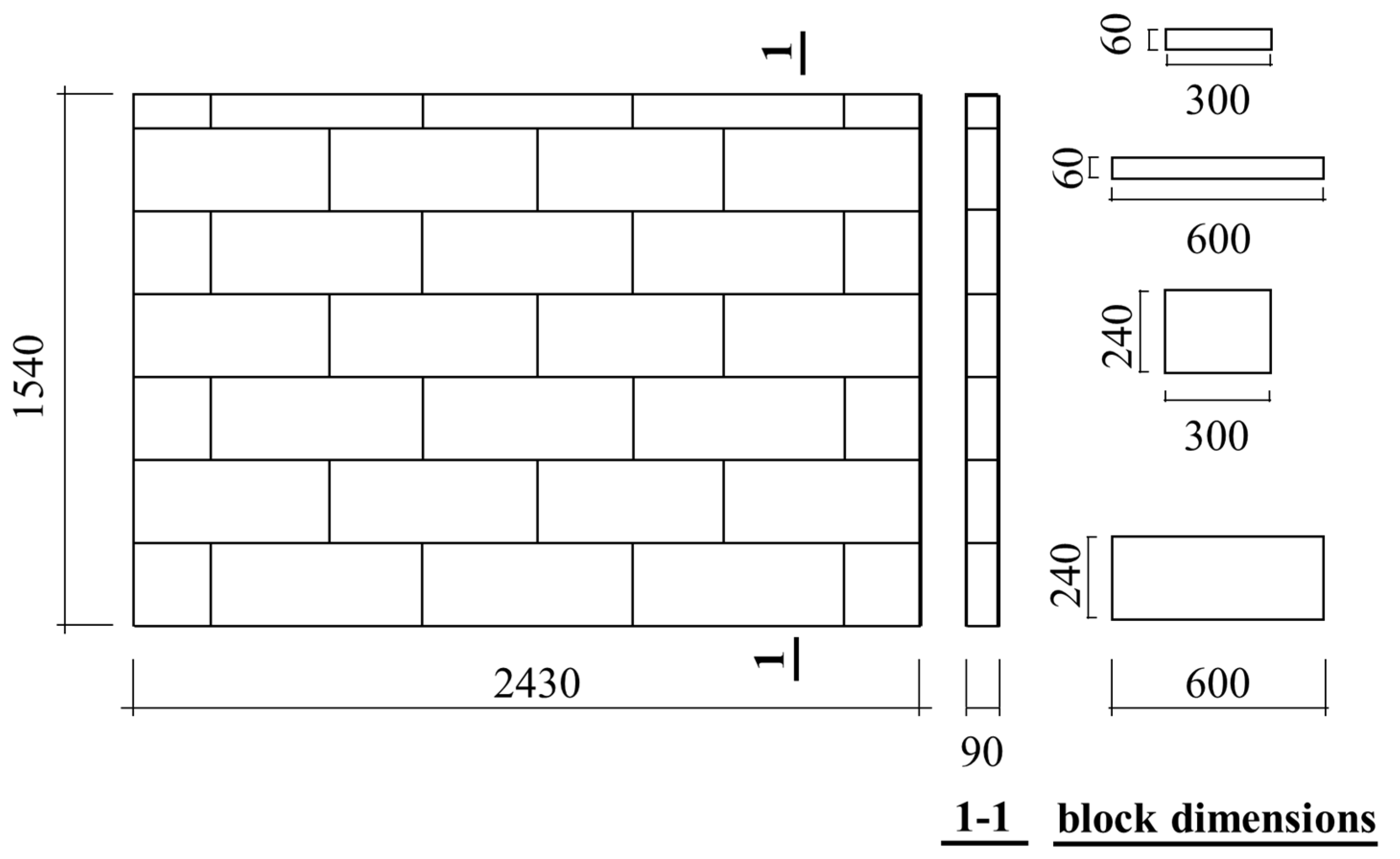
2. Experiment Overview

To verify the rationality of the proposed simplified model, the 1:2 scaled in-plane test specimen NF-1 and out-of-plane test specimen NF-2 from the seismic performance experiments on BFG strip-reinforced AAC masonry flexible connection infilled wall conducted by Wang [41] are selected as the finite element simulation objects.
According to the experiment conducted [41], the research focuses on the BFG strip-reinforced AAC masonry flexible connection infilled wall within the reinforced concrete frame structure erected on high-quality stiff soil. The stiffness of the foundation soil significantly exceeds that of the experimental frame structure. Given the considerable disparity in stiffness between the experimental frame structure and the foundation soil, with the latter being substantially stiffer, the foundation soil can be treated as rigid [57,58]. In accordance with Section 5.2.7 of China’s “Code for Seismic Design of Buildings” [26], seismic calculations for structures typically do not account for the interaction between the foundation soil and the structure. Therefore, in the experiment, the foundation soil is regarded as rigid, the soil does not undergo deformation, and the soil deformation has no effect on the structure.
As depicted in Figure 1, the specimen’s frame and infilled wall are erected on an I-shaped bottom beam. The frame columns are cast into the bottom beam, and the infilled wall is constructed on top of the bottom beam. The bottom beam is anchored to the ground, and flexible connections exist between the infilled wall and the frame. The dimensions and reinforcement details of the concrete frames are depicted in Figure 2. The concrete design strength grade is C30, with longitudinal reinforcement classified as HRB400 and stirrup reinforcement as HPB300. A protective layer thickness of 25 mm is maintained. The infilled wall comprises AAC blocks and specialized mortar, as illustrated in Figure 3. The specific dimensions of the infilled wall are detailed therein, with a height-to-thickness ratio of 17.3. A 20 mm gap is intentionally introduced between the infilled wall and the surrounding frame. The AAC blocks possess a strength grade of A3.5, while the specialized mortar is graded as Ma5.0. The BFG strips consist of connectors and BFG, with their schematic diagram presented in Figure 4. Type S1 strips employ horizontal L-shaped sliders as connectors, whereas Type S2 strips utilize clamps. Vertical L-shaped sliders are utilized for the connection between the infilled wall and the frame beam, as depicted in Figure 5, illustrating the arrangement of BFG strips and vertical L-shaped sliders.
In the finite element model, the columns of the frame have a height of 1560 mm, and the beams have a width of 2470 mm. The material parameters for the frame are based on C30 concrete constitutive parameters. The dimensions of the infilled wall model match those of the test specimens. The material parameters for the infilled wall are based on AAC masonry constitutive parameters. For the finite element model simulating in-plane loading, the arrangement of connectors is based on the in-plane test specimen NF-1. For the finite element model simulating out-of-plane loading, the arrangement of connectors is based on the out-of-plane test specimen NF-2. Based on the experiment [41], the finite element simulations do not need to account for the influence of foundation soil deformation on the model.

3. Simplified Model Establishment and Boundary Condition Settings

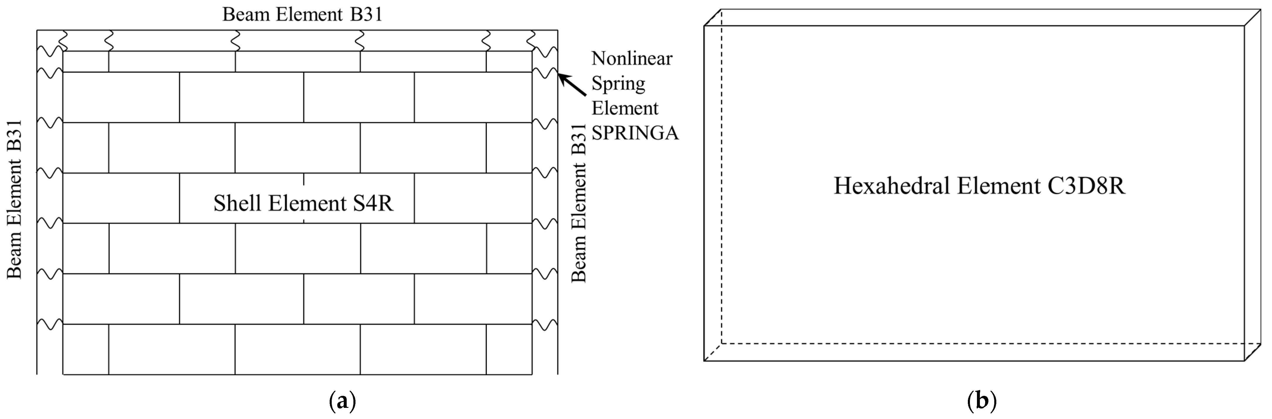
3.1. Frame and Infilled Wall Simplification

The beams and columns of the frame are modeled using two-node spatial linear beam elements B31, with a 25 mm steel reinforcement protective layer considered in the beam and column sections. Steel reinforcement is arranged in the beam elements using the keyword “rebar”. The infilled wall is simulated using four-node reduced integration shell elements S4R to model finite membrane strain. The airbags are simulated using eight-node linear hexahedral elements C3D8R. Schematic diagrams of the infilled frames model and the airbag model are shown in Figure 6.

3.2. Frame and Infilled Wall Simplification

The spring element SPRINGA is selected to simulate the flexible connectors between the wall and frame, connecting two points. The mechanical behavior of the SPRINGA element is achieved by defining the force–displacement relationship of the spring. The force applied to the connectors during out-of-plane tests is complex, requiring determination and simplification of the force–displacement relationship of the connectors for out-of-plane loading. The model’s springs utilize the simplified out-of-plane force–displacement relationship proposed by Chen [40] for different types of connectors, such as the simplified L-shaped slider and clamp. The force–displacement relationships for the L-shaped slider and clamp are illustrated in Figure 7.
According to the experiments [40,41], when the infilled wall is in the elastic stage, it is subjected to out-of-plane actions while being balanced by the reactive forces provided by the BFG strips, ultimately being supported in the form of concentrated shear by the L-shaped sliders. When the infilled wall cracks and enters the plastic stage, it mainly provides bearing capacity through the development of arch action, while the BFG strips mainly provide stable boundary constraints and out-of-plane tension ties for the wall, as shown in Figure 7a. During the experiment, a surplus length of 20 mm is left for BFG in the clamps, and the wall-frame nodes are not subjected to forces until the BFG strips is pulled straight. After the BFG strips is pulled straight, the clamps come into play, as shown in Figure 7b.

3.3. Boundary Condition and Loading Condition Settings

To achieve isolation between the infilled wall and the frame, a 20 mm gap width is reserved between the infilled wall model and the frame model. Based on the experiment [41], the foundation soil is regarded as rigid, the soil does not undergo deformation, and the soil deformation has no effect on the structure. As shown in Figure 1, the columns are cast into the bottom beam, and the infilled wall is constructed on top of the bottom beam, with the bottom beam anchored to the ground. In the experiment conducted in [41], whether subjected to in-plane or out-of-plane loading, no relative displacement is observed between the bottom of the frame columns and the bottom of the infill wall with respect to the bottom beam. It can be considered that the bottom of the infilled wall and the bottom of the frame are in a fixed state. Therefore, the boundary conditions at the bottom of the infilled wall and the bottom of the frame are set as fully fixed. To ensure coordinated motion between the infilled wall and the frame, the coupling method is employed to couple the degrees of freedom at corresponding connection points of connectors.
In the in-plane simulation, a horizontal reciprocating load is applied to the outer right sides of the frame model. Following the experimental loading protocol, the load is incrementally increased by 10 kN in each step, with each level cycled once. After yielding, displacement-controlled loading is employed, with the load incrementally increased by multiples of the yield displacement, cycled three times at each level.
In the out-of-plane simulation, a surface-to-surface contact is established between the airbag model and the infilled wall model. In the contact properties, the friction formula for tangential behavior is set to penalty, and the normal behavior is set to “hard” contact. To capture the descending phase of the out-of-plane bearing capacity, an implicit dynamic analysis is employed for the out-of-plane simulation test, with a set analysis time of 10 s. A 150 mm out-of-plane displacement is applied to the airbag model.

4. Material Constitutive Relationship

4.1. Reinforcement Constitutive Relationship

In the beam elements, the constitutive model for longitudinal reinforcement is implemented using the USteel02 model, developed by Qu [59] and suitable for Abaqus fiber beam elements in the PQ-Fiber subroutine. The material parameters for the reinforcement are provided in Table 1.

4.2. Concrete Constitutive Relationship

The stirrup divides the concrete into the core zone inside the stirrup and the non-core zone outside the stirrup. The core zone concrete is constrained by the stirrup and needs to be considered in the concrete constitutive model. For simplification purposes, the constraint of the stirrup is treated as a full-section constraint, and the distinction between the core and non-core zones is no longer made.
In the beam elements, the concrete constitutive model adopts the UConcrete02 model from PQ-Fiber, which considers the tensile strength of concrete. The confinement effect of stirrups can significantly enhance the ductility of structural components and suppress the nonlinear development of structures under seismic actions [60]. It is necessary to consider the enhancement of concrete mechanical properties due to the confinement effect of stirrups in concrete parameters. The restrained concrete model proposed by Mander et al. [61] is employed for these calculations. The material parameters for restrained concrete are provided in Table 2.

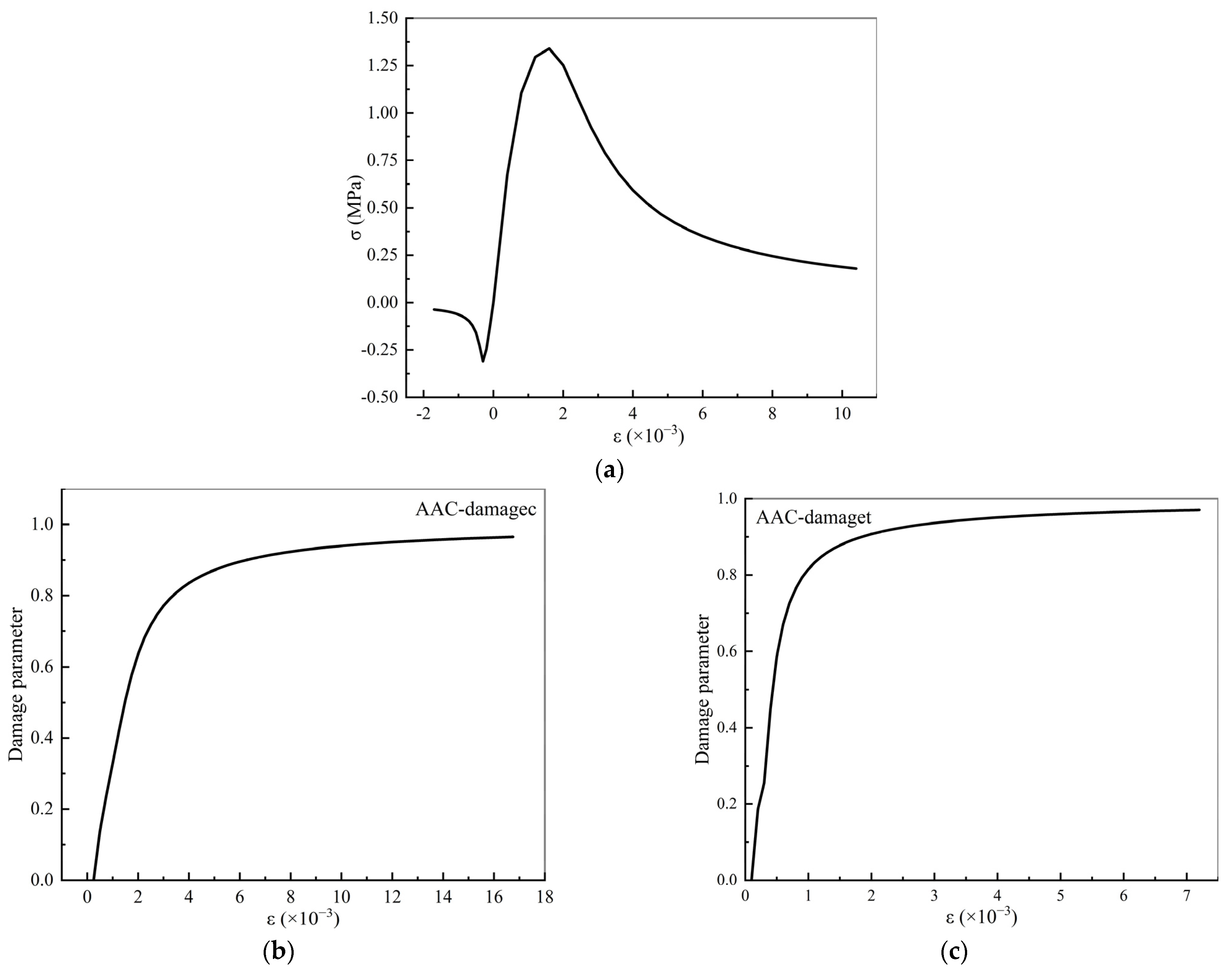
4.3. Autoclaved Aerated Concrete Masonry Constitutive Relationship

The AAC masonry model adopts the concrete damage plasticity (CDP) model for simulation. The CDP model parameters are provided in Table 3.
The AAC masonry consists of AAC blocks, BFG strips and high-strength mortar as wall units. Due to homogeneous modeling, it is considered a homogeneous material. The numerical simulation parameters for AAC masonry are referenced from material tests according to Luo [38], as detailed in Table 4.
The constitutive models for compressive and tensile behavior of AAC masonry are based on the equations proposed by Ye [62] and Li [63]. The uniaxial stress–strain curve and damage factor curves are illustrated in Figure 8.

4.4. Airbag Model Constitutive Relationship

The constitutive relationship of the airbag model adopts an isotropic linear elastic model. To ensure uniform pressure applied to the masonry model, the elastic modulus of the airbag model is set to 0.01 MPa, and the Poisson’s ratio is 0.1.

5. Comparison and Analysis of Calculation Results

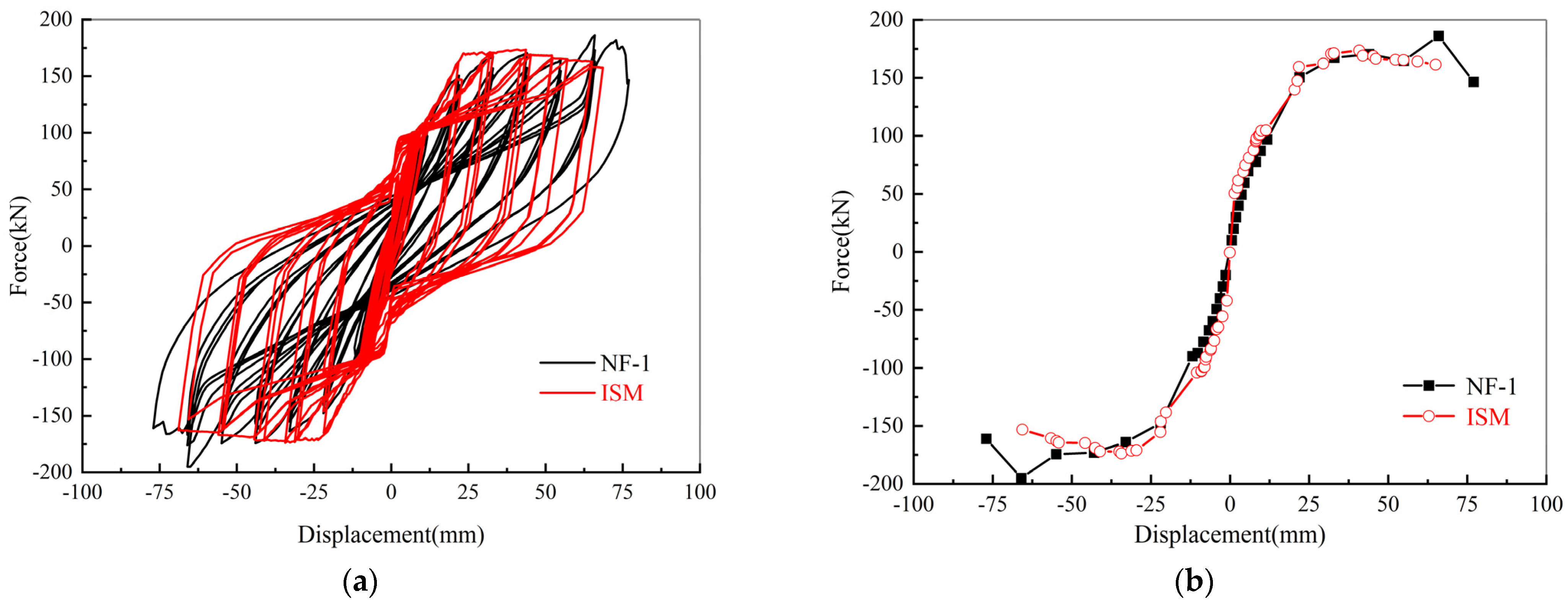
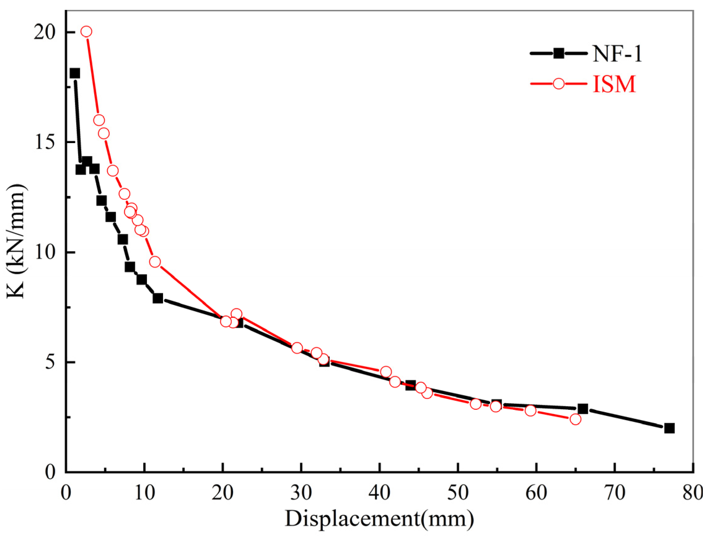
5.1. In-Plane Calculation Results

Using the in-plane simplified model (ISM) for in-plane simulation loading, the results are compared and analyzed with the results of specimen NF-1. The hysteresis curve and skeleton curve of the two are obtained, as shown in Figure 9.
From Figure 9, it can be observed that the in-plane hysteresis curve and skeleton curve of ISM closely resemble the curves of NF-1, showing good agreement. Both models exhibit similar initial stiffness, peak load-bearing capacity, and stiffness degradation patterns. The initial stiffness simulated by ISM is greater than the experimental value. This discrepancy arises from ISM’s use of linear beam elements to simulate the beams and columns of the specimen, neglecting the impact of internal steel reinforcement and concrete slip-on structural stiffness. Additionally, in setting concrete parameters, ISM considers the entire cross-section, ignoring the distinction between inner and outer reinforcement, leading to a certain degree of error. Due to considerations of load degradation in the steel reinforcement constitutive model during cyclic loading and the cumulative damage effects in the material models, both ISM and NF-1 hysteresis and skeleton curves exhibit noticeable asymmetry in computed values. In the later stages of NF-1 hysteresis loading, there is an increase in load-carrying capacity with each cycle, resulting in a larger hysteresis area and a serrated pattern near the peak. This behavior is attributed to the participation of the infilled wall in the structural load and its subsequent brittle failure. On the other hand, ISM, using simplified elements, cannot simulate the load-carrying capacity increase stage, where the infilled wall participates in the structural load, leading to the absence of a load-up phase.
The comparison of the stiffness degradation curves between ISM and NF-1 is illustrated in Figure 10.
From Figure 10, it can be observed that the stiffness degradation levels of the ISM and NF-1 flexible connection infilled frames are essentially consistent. The structural stiffness of both ISM and NF-1 decreases rapidly in the early stages, reaching around 60% of the initial stiffness before a loading of 6 mm. Prior to a loading of 20 mm, the ISM structural stiffness is slightly higher than the experimental value, which is attributed to the neglect of internal steel reinforcement and concrete slip within the framework, as discussed earlier. After a loading of 20 mm, the degradation levels of stiffness for both models are essentially consistent, at which point the infilled wall becomes the main contributor to the structural stiffness degradation.
The comparison of strength degradation between ISM and NF-1 is shown in Figure 11, where the horizontal axis represents the ratio of displacement for each displacement-controlled stage to the unit displacement, and the vertical axis represents the normalized values of the load at each stage of the three-level loading normalized by the maximum load.
From Figure 11, it can be observed that there is a slight difference in the strength degradation between ISM and NF-1. The strength degradation at each level in NF-1 is slightly smaller than that in ISM. This difference may be attributed to the fact that in ISM, the state where the connectors do not participate in the overall stiffness is an idealized condition. In reality, when connectors are used (as in NF-1), there is a slight increase in the overall stiffness of the frame. Moreover, the higher degree of involvement of the infilled wall in the structural loading in NF-1 contributes to a slightly slower overall degradation of the frame.

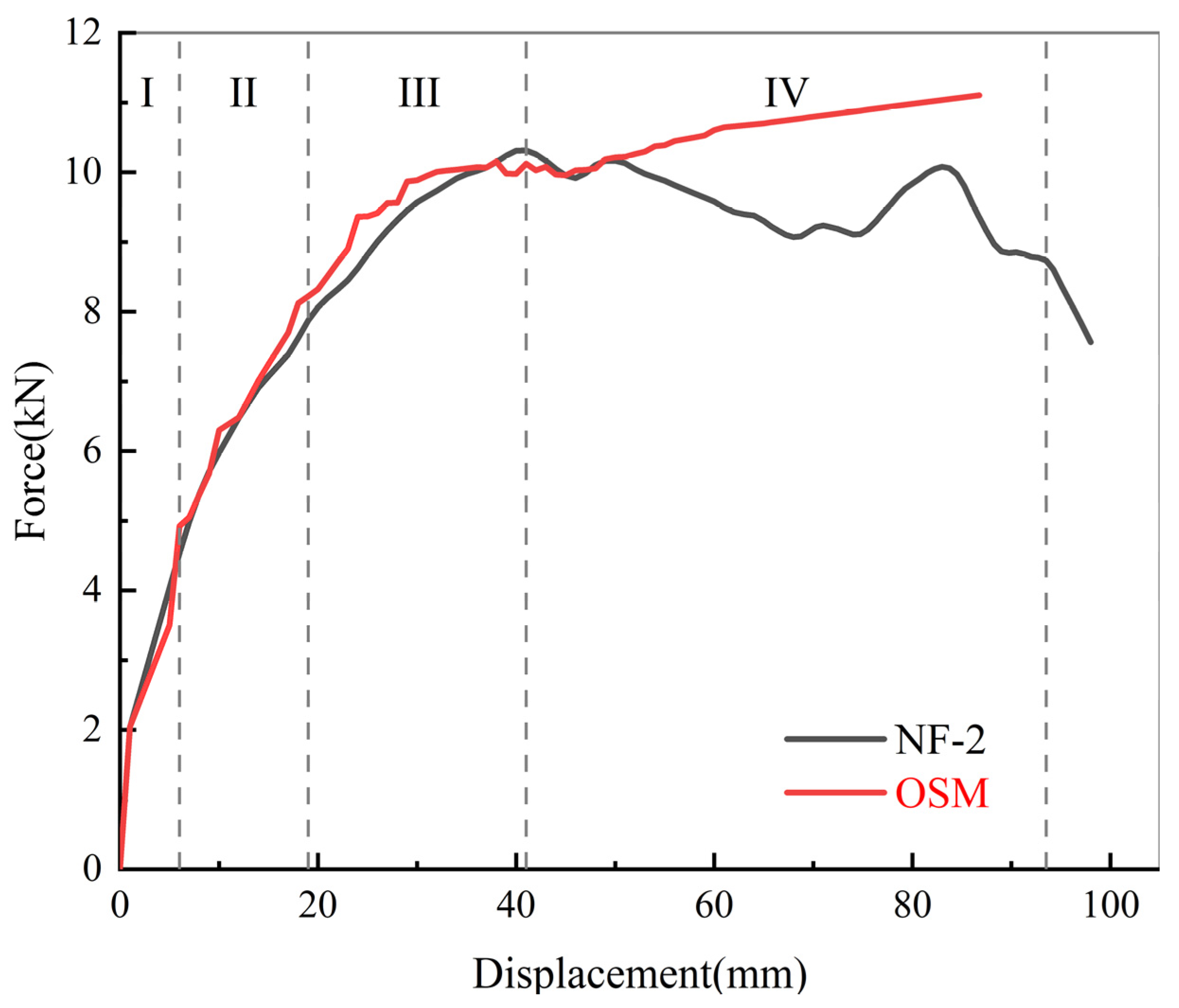
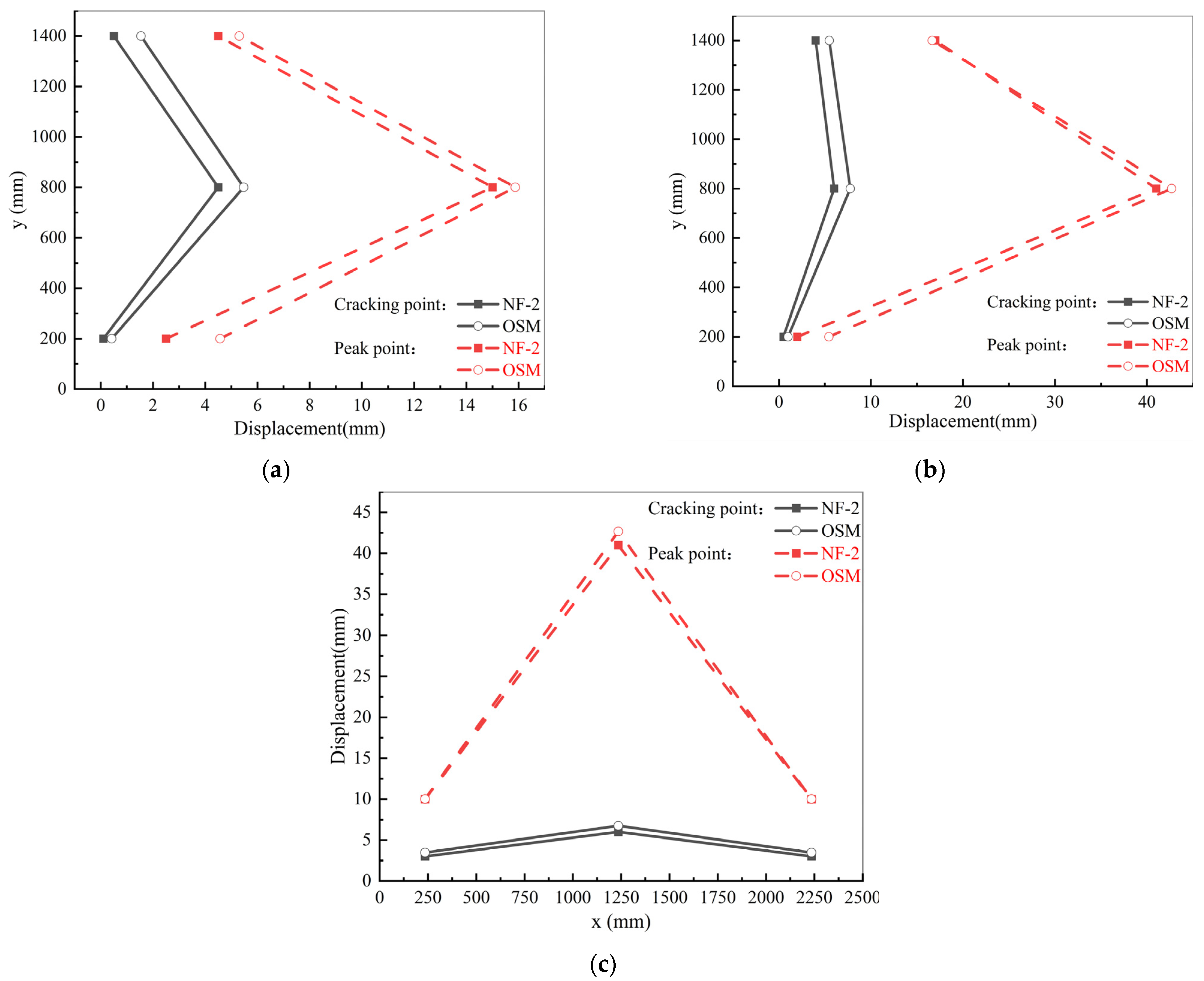
5.2. Out-of-Plane Calculation Results

Using the out-of-plane simplified model (OSM) for out-of-plane simulation loading, the results are compared and analyzed with the results of specimen NF-2. Referring to the analysis of out-of-plane test results by Wang [55], the displacement–force relationship of the NF-2 infilled wall out-of-plane mid-point is divided into four developmental stages:
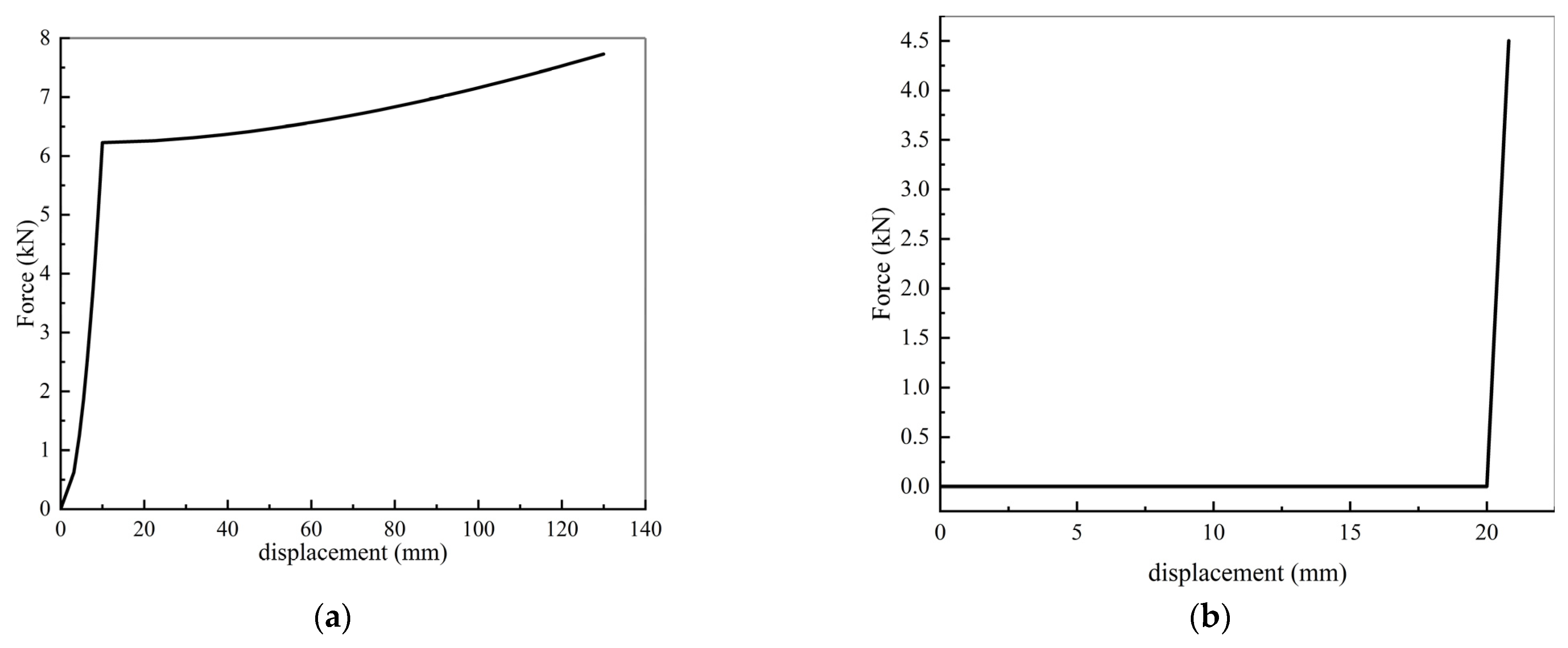
  • Pseudo-linear stage (Stage I): before the wall cracks, the out-of-plane force–displacement relationship is approximately linear.
  • Strengthening stage (Stage II): the wall enters a plastic state, and its out-of-plane stiffness gradually decreases.
  • Yielding stage (Stage III): the out-of-plane load-carrying capacity of the wall gradually reaches its peak, accompanied by significant out-of-plane deformation.
  • Degradation stage (Stage IV): The out-of-plane load-carrying capacity of the wall starts to degrade and decreases to below 85% of the ultimate load-bearing capacity.
The four performance points, namely the cracking point, yielding point, peak point, and failure point, are identified. The displacement–force curves of the out-of-plane midpoints for the OSM and NF-2 are categorized into the aforementioned stages, as shown in Figure 12. The specific values of performance points at different development stages in the experiment are listed in Table 5.
From Figure 12, it can be observed that the displacement–load curve of the OSM mid-point out-of-plane motion fits well during the pseudo-linear, strengthening, and yielding stages. After the yielding stage, the OSM curve shows an upward trend that deviates from NF-2. The occurrence of the rising segment may be attributed to the fact that the OSM model, which adopts a homogenized integral modeling approach for the infilled wall, cannot simulate the mortar cracking between the blocks in response to out-of-plane loads. Instead, it relies on the tensile deformation of elements to enhance the OSM’s ultimate load-carrying capacity, showing a more pronounced arching effect compared to NF-2. The second rising segment of the OSM curve appears after the peak load point of NF-2. However, before the peak load point of NF-2, the OSM accurately simulates the variation relationship between displacement and load in NF-2.
As OSM exhibits good fitting before the degradation stage, a comparison of the out-of-plane displacement distribution between OSM and NF-2 infilled walls at the cracking and peak points is depicted in Figure 13.
Figure 13 illustrates that OSM and NF-2 exhibit a certain degree of similarity in the out-of-plane displacement distribution in the wall-end vertical direction, wall-middle vertical direction, and wall-middle horizontal direction. At the cracking point, the out-of-plane displacement of the wall in both OSM and NF-2 is significantly smaller than at the peak point. For OSM, the maximum plastic range in the vertical direction at the wall end, vertical direction at the middle of the wall, and horizontal direction at the middle of the wall are 9.98 mm, 33.92 mm, and 33.92 mm, respectively. For NF-2, the maximum plastic ranges in the vertical direction at the wall end, vertical direction at the middle of the wall, and horizontal direction at the middle of the wall are 10.5 mm, 35 mm, and 35 mm, respectively. The differences between OSM and NF-2 are 5%, 3%, and 3%, respectively. This indicates that both OSM and NF-2 have significant plastic ranges, and their plastic ranges are comparable. The out-of-plane vertical displacement at the end of the wall is smaller than that at the middle of the wall, suggesting that both OSM and NF-2 effectively exhibit arching behavior. The distribution of out-of-plane displacement at the wall-middle vertical direction is relatively uneven, and the displacement at the lower end (200 mm) is smaller than at the upper end (1400 mm), indicating that the constraints from the fixed supports are stronger than those from the connectors. The out-of-plane displacement distribution at the wall-end vertical direction, wall-middle vertical direction, and wall-middle horizontal direction of OSM is slightly larger than the NF-2 data. At the cracking point, the maximum differences between the out-of-plane displacement of NF-2 and OSM in the vertical direction at the wall end, vertical direction at the middle of the wall, and horizontal direction at the middle of the wall are 0.97 mm, 1.75 mm, and 1.75 mm, respectively. At the peak point, the maximum differences between the out-of-plane displacement of NF-2 and OSM in the vertical direction at the wall end, vertical direction at the middle of the wall, and horizontal direction at the middle of the wall are 2.07 mm, 2.43 mm, and 1.68 mm, respectively. The possible reason is that in NF-2, after the mortar fractures, the BFG strips located in the mortar play a constraining role, whereas the infilled wall model of OSM is a homogeneous model that cannot reflect the constraining effect of BFG on the real wall’s out-of-plane displacement.

6. Discussion

Compared with the solid unit model of the BFG strip-reinforced AAC masonry flexible connection infilled wall [39,40,41], the simplified model proposed in this paper improves computational efficiency while ensuring a certain level of accuracy. It is suitable for simulating studies on individual components as well as for modeling large structures in seismic resilience assessments of buildings. Compared to other simplified models [56], this simplified model can simulate out-of-plane loading, thus expanding its applicability to a wider range of scenarios.
The simplified model proposed in this paper still has some limitations. It cannot simulate the force–displacement relationship after reaching the peak point of load capacity under out-of-plane loading, nor can it simulate the failure of the wall under in-plane and out-of-plane loading of the infilled wall.
In future research, this study will focus on component vulnerability assessment of the BFG strip-reinforced AAC masonry flexible connection infilled wall by using the simplified model. Subsequently, research will be conducted on seismic resilience assessment methods for structures with BFG strip-reinforced AAC masonry flexible connection infilled walls. In future studies, soil effects on building structures will be taken into consideration.

7. Conclusions

This paper, based on a homogenized approach, establishes a three-dimensional simplified model of the BFG strip-reinforced AAC masonry flexible connection infilled wall using the finite element method. Through simulating seismic performance tests on BFG strip-reinforced AAC masonry in-filled walls, including in-plane loading tests and out-of-plane loading tests, and comparing the results with the in-plane test specimen NF-1 and out-of-plane test specimen NF-2, the following findings are obtained:
  • The simplified model, utilizing beam elements to simulate frame components, shell elements to simulate infill walls, and spring elements to simulate connectors, can effectively and reliably simulate specimens of BFG strip-reinforced AAC masonry flexible connection infilled walls. By defining the force–displacement relationship of the spring elements, it is possible to simulate different types of connectors.
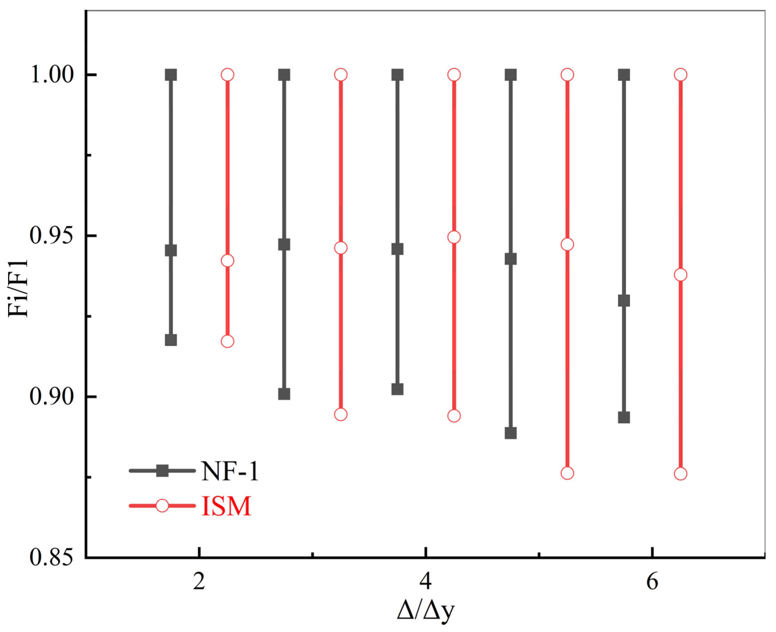
  • The simulation of in-plane loading indicates that the hysteresis curve and skeleton curve of ISM exhibit similarity to NF-1, exhibiting similar initial stiffness, peak bearing capacity, stiffness degradation behavior, and strength attenuation behavior. By adjusting the size parameters, material parameters, and force–displacement relationship of the springs in the model, it is possible to achieve in-plane loading simulation of flexible connection infilled walls with different materials.
  • The simulation of out-of-plane loading indicates that the OSM curve in the pseudo-linear, strengthening, and yielding stages exhibits similarities to NF-2. At the crack and peak points, the arching effect of the OSM is similar to that of NF-2, exhibiting a significant plastic range. The maximum plastic range of the two is only 5% different. Due to the poor simulation performance after the peak point, it is recommended to use the OSM for out-of-plane loading simulation of flexible connection infilled walls, focusing solely on the force–displacement relationship before the peak point. Similarly, by adjusting the size parameters, material parameters, and force–displacement relationship of the springs in the model, it is possible to achieve out-of-plane loading simulation of flexible connection infilled walls with different materials.
The simplified model proposed in this paper strikes a balance between computational efficiency and accuracy, expanding the application scope of existing models and providing a new approach for modeling large structures. It holds promising prospects for further development.

Author Contributions

Conceptualization, L.X.; methodology, L.X.; software, X.W.; validation, X.W., L.X. and Z.W.; formal analysis, X.W.; investigation, X.W., L.X. and Z.W.; resources, L.X. and Z.W.; data curation, X.W.; writing—original draft preparation, X.W.; writing—review and editing, L.X. and Z.W.; visualization, X.W. and Z.W.; supervision, L.X.; project administration, L.X.; funding acquisition, L.X. All authors have read and agreed to the published version of the manuscript.

Funding

This research was funded by the Scientific Research Fund of Institute of Engineering Mechanics, China Earthquake Administration, grant number 2019B07 and the Key Project of Key Laboratory of Earthquake Engineering and Engineering Vibration, Institute of Engineering Mechanics, China Earthquake Administration, grant number 2021EEEVL0302.

Data Availability Statement

The original contributions presented in the study are included in the article, further inquiries can be directed to the corresponding author.

Conflicts of Interest

The authors declare no conflicts of interest.

References

  1. Liu, X.; Jiang, H. State-of-the-art of performance-based seismic research on nonstructural components. Earthq. Eng. Eng. Vib. 2013, 33, 53–62. (In Chinese) [Google Scholar]
  2. He, S.; Qu, Z.; Zhou, H.; Dai, J.; Wang, D. State of the art of testing methods for nonstructural components in seismic areas. China Civ. Eng. J. 2017, 50, 16–27. (In Chinese) [Google Scholar]
  3. Dias-Oliveira, J.; Rodrigues, H.; Asteris, P.G.; Varum, H. On the Seismic Behavior of Masonry Infilled Frame Structures. Buildings 2022, 12, 1146. [Google Scholar] [CrossRef]
  4. Charleson, A. Seismic Design for Architects; Routledge: London, UK, 2008. [Google Scholar]
  5. Tabeshpour, M.R.; Azad, A.; Golafshani, A.A. Seismic behavior and retrofit of infilled frames. In Earthquake-Resistant Structures—Design, Assessment and Rehabilitation; IntechOpen: London, UK, 2012; pp. 280–306. [Google Scholar]
  6. Abdel-Hafez, L.M.; Abouelezz, A.E.Y.; Elzefeary, F.F. Behavior of masonry strengthened infilled reinforced concrete frames under in-plane load. HBRC J. 2015, 11, 213–223. [Google Scholar] [CrossRef]
  7. Perrone, D.; Leone, M.; Aiello, M.A. Evaluation of the infill influence on the elastic period of existing RC frames. Eng. Struct. 2016, 123, 419–433. [Google Scholar] [CrossRef]
  8. Paulay, T.; Priestley, M.J.N. Seismic Design of Reinforced Concrete and Masonry Buildings; Wiley: New York, NY, USA, 1992. [Google Scholar]
  9. Sattar, S.; Liel, A.B. Seismic performance of reinforced concrete frame structures with and without masonry infilled walls. In Proceedings of the 9th U.S. National and 10th Canadian Conference on Earthquake Engineering, Toronto, ON, Canada, 25–29 July 2010. [Google Scholar]
  10. Mosalam, K.M.; Günay, S. Progressive collapse analysis of reinforced concrete frames with unreinforced masonry infilled walls considering in-plane/out-of-plane interaction. Earthq. Spectra 2015, 31, 921–943. [Google Scholar] [CrossRef]
  11. Papatheodorou, K.; Theodoulidis, N.; Klimis, N.; Zulfikar, C.; Vintila, D.; Cardanet, V.; Kirtas, E.; Toma-Danila, D.; Margaris, B.; Fahjan, Y.; et al. Rapid Earthquake Damage Assessment and Education to Improve Earthquake Response Efficiency and Community Resilience. Sustainability 2023, 15, 16603. [Google Scholar] [CrossRef]
  12. Takagi, J.; Wada, A. Recent earthquakes and the need for a new philosophy for earthquake-resistant design. Soil Dyn. Earthq. Eng. 2019, 119, 499–507. [Google Scholar] [CrossRef]
  13. Mohammadi, M.; Akrami, V. An engineered infilled frame: Behavior and calibration. J. Constr. Steel Res. 2010, 66, 842–849. [Google Scholar] [CrossRef]
  14. Morandi, P.; Milanesi, R.R.; Magenes, G. Innovative seismic solution for clay masonry infills with sliding joints: Principles and details. In Proceedings of the 16th International Brick and Block Masonry Conference, Padova, Italy, 26–30 June 2016. [Google Scholar]
  15. Preti, M.; Bettini, N.; Plizzari, G. Infilled walls with sliding joints to limit infill-frame seismic interaction: Large-scale experimental test. J. Earthq. Eng. 2012, 16, 125–141. [Google Scholar] [CrossRef]
  16. Ju, R.S.; Lee, H.J.; Chen, C.C.; Tao, C.C. Experimental study on separating reinforced concrete infilled walls from steel moment frames. J. Constr. Steel Res. 2012, 71, 119–128. [Google Scholar] [CrossRef]
  17. Ahmadi, H.; Dusi, A.; Gough, J. A rubber-based system for damage reduction in infill masonry walls. In Proceedings of the 16th World Conference on Earthquake Engineering, Santiago, Chile, 9–13 January 2017. [Google Scholar]
  18. Tsantilis, A.V.; Triantafillou, T.C. Innovative seismic isolation of masonry infills using cellular materials at the interface with the surrounding RC frames. Eng. Struct. 2018, 155, 279–297. [Google Scholar] [CrossRef]
  19. Kumar, S.M.; Satyanarayanan, K.S. Study the effect of elastic materials as interface medium used in infilled frames. Mater. Today Proc. 2018, 5, 8986–8995. [Google Scholar]
  20. Marinković, M.; Butenweg, C. Innovative system for earthquake resistant masonry infilled walls. In Proceedings of the 16th European Conference on Earthquake Engineering, Thessaloniki, Greece, 18–21 June 2018. [Google Scholar]
  21. Ghamari, A.; Khaloo, A. An innovative infilled wall utilizing light expanded clay aggregate: An experimental and numerical study. Struct. Des. Tall Spec. Build. 2020, 29, e1791. [Google Scholar] [CrossRef]
  22. Umar, Z.; Shah, S.A.A.; Bibi, T.; Shahzada, K.; Ahmad, A. Innovative seismic isolation of masonry infills using cellular material at the interface with the surrounding RC frame. J. Build. Eng. 2021, 40, 102736. [Google Scholar] [CrossRef]
  23. Wang, Z.; Xiong, L.; Chen, G.; Luo, M.; Zhang, S. Out-of-plane performance of infilled frames with the improved flexible connection. J. Build. Eng. 2022, 51, 104286. [Google Scholar] [CrossRef]
  24. ASCE/SEI 41-13; Seismic Evaluation and Retrofit of Existing Buildings. American Society of Civil Engineers: Reston, VA, USA, 2014.
  25. NZS 4320; New Zealand Standard, Design of Reinforced Concrete Masonry Structures. Standards New Zealand: Wellington, New Zealand, 2014.
  26. GB 50011-2010; Code for Seismic Design of Buildings. Ministry of Housing and Urban-Rural Development of the People’s Republic of China: Beijing, China, 2016. (In Chinese)
  27. JGJ339-2015; Code for Seismic Design of Non-Structural Components. Ministry of Housing and Urban-Rural Development of the People’s Republic of China: Beijing, China, 2015. (In Chinese)
  28. Aliaari, M.; Memari, A.M. Analysis of masonry infilled steel frames with seismic isolator subframes. Eng. Struct. 2005, 27, 487–500. [Google Scholar] [CrossRef]
  29. Kauffman, A.; Memari, A.M. Performance Evaluation of Different Masonry Infilled walls with Structural Fuse Elements Based on In-Plane Cyclic Load Testing. Buildings 2014, 4, 605–634. [Google Scholar] [CrossRef]
  30. Tasligedik, A.S.; Pampanin, S.; Palermo, A. Low damage seismic solutions for non-structural drywall partitions. Bull. Earthq. Eng. 2015, 13, 1029–1050. [Google Scholar] [CrossRef]
  31. Tasligedik, A.S.; Pampanin, S. Rocking cantilever clay brick infilled wall panels: A novel low damage infilled wall system. J. Earthq. Eng. 2017, 21, 1023–1049. [Google Scholar] [CrossRef]
  32. Saad, A.S.; Ahmed, T.A.; Radwan, A.I. In-Plane Lateral Performance of AAC Block Walls Reinforced with CFPR Sheets. Buildings 2022, 12, 1680. [Google Scholar] [CrossRef]
  33. Erdem, M.M.; Emsen, E.; Bikçe, M. Experimental and numerical investigation of new flexible connection elements between infilled walls-RC frames. Constr. Build. Mater. 2021, 296, 123605. [Google Scholar] [CrossRef]
  34. Zhou, X.; Cheng, C.; Du, J.; Chen, K.; Chen, P. Seismic performance test of frame structure infilled with steaming gassed concrete masonry. World Earthq. Eng. 2022, 38, 46–57. (In Chinese) [Google Scholar]
  35. CECS 289-2011; Technical Code for Masonry Structure of Autoclaved Aerated Concrete Block. China Association for Engineering Construction Standardization: Beijing, China, 2011. (In Chinese)
  36. Xiong, L.; Chen, G.; Lin, D.; Luo, M.; Yang, C. Test on basic mechanical properties of autoclaved aerated concrete block masonry with basalt fiber grille. Build. Sci. 2017, 33, 48–54. (In Chinese) [Google Scholar]
  37. Chen, G. Experimental Study on Seismic Performance of BFG Autoclaved Aerated Concrete Block Infilled Wall Frame. Master’s Thesis, China Earthquake Administration Institute of Engineering Mechanics, Harbin, China, 2017. [Google Scholar]
  38. Luo, M. Study on Out-of-plane Seismic Behavior of BFG Reinforced Masonry Infilled Wall with Flexible Connections. Master’s Thesis, China Earthquake Administration Institute of Engineering Mechanics, Harbin, China, 2018. [Google Scholar]
  39. Liu, J. ABAQUS-based Research on Seismic Performance of Reinforced Masonry Infilled wall with Flexible Connections. Master’s Thesis, China Earthquake Administration Institute of Engineering Mechanics, Harbin, China, 2019. [Google Scholar]
  40. Chen, D. Numerical Simulation for Seismic Performance of Flexible Connection Masonry-Infilled RC Frames. Master’s Thesis, China Earthquake Administration Institute of Engineering Mechanics, Harbin, China, 2020. [Google Scholar]
  41. Wang, Z. Seismic Performance and Fragility Analysis of Infilled Frames with the Improved Flexible Connection. Master’s Thesis, China Earthquake Administration Institute of Engineering Mechanics, Harbin, China, 2022. [Google Scholar]
  42. Forcellini, D. An expeditious framework for assessing the seismic resilience (SR) of structural configurations. Structures 2023, 53, 105015. [Google Scholar] [CrossRef]
  43. Kourehpaz, P.; Molina, H.C. Machine learning for enhanced regional seismic risk assessments. J. Struct. Eng. 2022, 148, 4022126. [Google Scholar] [CrossRef]
  44. Rasool, A.M.; Afzal, M.F.U.D.; Rashid, M.U. Enhancing Seismic Resilience: Evaluating Buildings with Passive Energy Dissipation Strategies. Eng 2024, 5, 367–383. [Google Scholar] [CrossRef]
  45. Jiang, S.; Chen, Q.; Li, C.; Song, H.; Lin, E.; Fu, C. Assessment of Soft-First-Floor Structures Reinforced by Rocking Frame Based on Seismic Resilience. Buildings 2024, 14, 197. [Google Scholar] [CrossRef]
  46. Cui, H.; Tao, R.; Bao, X.; Wu, X.; Qiu, T.; Shen, J.; Han, Z.; Chen, X. Seismic Resilience Evolution of Shield Tunnel with Structure Degradation. Appl. Sci. 2024, 14, 72. [Google Scholar] [CrossRef]
  47. Li, P.; Li, X.; Wang, X.; Wang, D. Seismic Resilience Evaluation of Reinforced Concrete Frame Considering the Effect of Mainshock-Aftershock Sequences. Appl. Sci. 2023, 13, 12620. [Google Scholar] [CrossRef]
  48. Prasanth, S.; Ghosh, G.; Gupta, P.K.; Casapulla, C.; Giresini, L. Accounting for Resilience in the Selection of R Factors for a RC Unsymmetrical Building. Appl. Sci. 2023, 13, 1316. [Google Scholar] [CrossRef]
  49. Joyner, M.D.; Sasani, M. Building performance for earthquake resilience. Eng. Struct. 2020, 210, 110371. [Google Scholar] [CrossRef]
  50. FEMA-P58; Seismic Performance Assessment of Buildings. Federal Emergency Management Agency: Washington, DC, USA, 2012.
  51. GB 38591-2020; Standard for Seismic Resilience Assessment of Buildings. State Administration for Market Regulation, Standardization Administration of the People’s Republic of China: Beijing, China, 2020. (In Chinese)
  52. Almufti, I.; Willford, M. REDi™ Rating System: Resilience-Based Earthquake Design Initiative for the Next Generation of Buildings; Arup Co.: London, UK, 2013. [Google Scholar]
  53. Mayes, R.L.; Reis, E. The US Resiliency Council (USRC) and the building rating system. In Proceedings of the SEI Conference on Improving the Seismic Performance of Existing Buildings and Other Structures, San Francisco, CA, USA, 10–12 December 2015. [Google Scholar]
  54. El Haddad, M.H. Finite element analysis of infilled frames considering cracking and separation phenomena. Comput. Struct. 1991, 41, 439–447. [Google Scholar] [CrossRef]
  55. Liu, L.; Tang, X. The non-linear finite element analysis of reinforced concrete frame structures with slit masonry filler wall. J. Suzhou Univ. Sci. Technol. (Eng. Technol.) 2010, 23, 49–53. (In Chinese) [Google Scholar]
  56. Zhou, X.; Chen, P.; Wang, Y. Finite element calculation and experiment comparison about masonry-infilled frame structure considering connection ways between infilled wall and frame. World Earthq. Eng. 2015, 31, 188–195. (In Chinese) [Google Scholar]
  57. Liu, Y. Study on Modeling Method of Tall-Building’s Dynamic Soil-Structure Interaction Based on Massless Base. Master’s Thesis, Beijing Jiaotong University, Beijing, China, 2008. [Google Scholar]
  58. Chen, S. Research on Seismic Vulnerability of Steel Frame on Soft Soil Foundation Considering Group Effect. Master’s Thesis, Southeast University, Nanjing, China, 2021. [Google Scholar]
  59. Qu, Z. PQ-Fiber. Available online: http://www.qu-zhe.net/pqfiber.htm (accessed on 1 September 2022).
  60. Gong, M.; Yang, D.; Zhang, J. Study on the application of stirrup-confined concrete constitutive models in elastic-plastic analysis. Build. Struct. 2022, 52, 45–52. (In Chinese) [Google Scholar]
  61. Mander, J.B.; Priestley, M.J.N.; Park, R. Theoretical stress-strain model for confined concrete. J. Struct. Eng. 1988, 114, 1804–1826. [Google Scholar] [CrossRef]
  62. Ye, L.; Lu, J.; Qin, S.; Zhang, J. Research on compressive performance of autoclaved aerated concrete masonry. In Proceedings of the 2012 National Academic Conference on Basic Theory and Engineering Application in the field of Masonry Structure, Hangzhou, China, 10–13 November 2012; pp. 211–217. [Google Scholar]
  63. Li, Z.; Cheng, C. Experimental and finite element analysis for the flexural performance of autoclaved aerated concrete floor slabs. Struct. Eng. 2014, 30, 165–170. (In Chinese) [Google Scholar] [CrossRef]
Figure 1. The frame and infilled wall schematic.
Buildings 14 01033 g001
Figure 2. Concrete frame size and reinforcement details (unit: mm).
Buildings 14 01033 g002
Figure 3. Infilled wall size (unit: mm).
Buildings 14 01033 g003
Figure 4. Schematic of BFG strips.
Buildings 14 01033 g004
Figure 5. Arrangement of BFG strips: (a) NF-1; (b) NF-2.
Buildings 14 01033 g005
Figure 6. Model schematics: (a) infilled frame model; (b) airbag model.
Buildings 14 01033 g006
Figure 7. Connectors out-of-plane force–displacement curves: (a) L-shaped slider; (b) clamp.
Buildings 14 01033 g007
Figure 8. AAC masonry mechanical property curves: (a) uniaxial stress–strain curve; (b) compressive damage factor curve; (c) tensile damage factor curve.
Buildings 14 01033 g008
Figure 9. Hysteresis curve and skeleton curve comparison: (a) hysteresis curve; (b) skeleton curve.
Buildings 14 01033 g009
Figure 10. Stiffness degradation comparison.
Buildings 14 01033 g010
Figure 11. Strength degradation comparison.
Buildings 14 01033 g011
Figure 12. OSM and NF-2 filled wall stage division for displacement–force curve of out-of-plane midpoint.
Buildings 14 01033 g012
Figure 13. Out-of-plane displacements at different locations comparison: (a) vertical displacement at the end of the wall; (b) vertical displacement at the middle of the wall; (c) horizontal displacement at the middle of the wall.
Buildings 14 01033 g013
Table 1. Reinforcement model material parameters.
TypeES0 1 (MPa)fy 2 (MPa)α 3Ultimate Plastic Deformation Rate (%)α1 4
HRB4002e54000.001500
1 ES0 is the elastic modulus of reinforcement. 2 fy is the yield strength of reinforcement. 3 α is the stiffness coefficient after yield. 4 α1 is the stiffness proportional damping coefficient.
Table 2. Restrained concrete material parameters.
Positionfcc0 1 (MPa)εcc0 2fccu 3 (MPa)εccu 4dccu 5fcct 6 (MPa)γSEC 7Sy 8
Beam28.580.0052824.290.02520.52.9722800.00261
Column29.20.0055524.820.02640.5322800.00263
1 fcc0 is the axial compressive strength of restrained concrete. 2 εcc0 is the peak compressive strain of restrained concrete. 3 fccu is the ultimate compressive strength of restrained concrete. 4 εccu is the ultimate compressive strain of restrained concrete. 5 dccu is the ratio of unloading stiffness to initial elastic modulus when the ultimate compressive strain is reached. 6 fcct is the axial tensile strength of restrained concrete. 7 γSEC is the tensile softening modulus, γS = 0.1. 8 Sy is the yield strain of cross-sectional reinforcement.
Table 3. CDP model parameters.
Dilation Angle (°)Eccentricity Biaxial Ultimate Compressive Strength Uniaxial Ultimate Compressive Strength Yield ConstantViscosity Coefficient
300.11.160.6670.005
Table 4. AAC masonry numerical simulation parameters.
MaterialES 1 (MPa)fc 2 (MPa)ft 3 (MPa)ν 4ρ 5 (Kg/m3)
AAC masonry1856.332.900.6570.36602.3
1 ES is the elastic modulus of AAC masonry. 2 fc is the uniaxial compressive strength of AAC masonry. 3 ft is the axial tensile strength of AAC masonry. 4 ν is the Poisson’s ratio of AAC masonry. 5 ρ is the density of AAC masonry.
Table 5. NF-2 performance points.
Pseudo-Linear Stage (I)Strengthening—Yielding Stage (II–III)Degradation Stage (IV)
Cracking PointYielding Point 1Peak PointFailure Point
Load (kN)Displacement 2 (mm)Load (kN)Displacement 2 (mm)Load (kN)Displacement 2 (mm)Load (kN)Displacement 2 (mm)
4.56.007.8719.0010.3141.008.7393.50
1 The yield load of the infilled wall corresponds to the point where the load–displacement curve shows a significant inflection point or where the stiffness degrades to 0.2 times the initial stiffness. 2 The displacement of the infilled wall refers to the out-of-plane displacement at the mid-point of the wall.
Disclaimer/Publisher’s Note: The statements, opinions and data contained in all publications are solely those of the individual author(s) and contributor(s) and not of MDPI and/or the editor(s). MDPI and/or the editor(s) disclaim responsibility for any injury to people or property resulting from any ideas, methods, instructions or products referred to in the content.

