Article

A Parametric Study Investigating the Dowel Bar Load Transfer Efficiency in Jointed Plain Concrete Pavement Using a Finite Element Model

by
Saima Yaqoob
1,*,
Johan Silfwerbrand
1 and
Romain Gabriel Roger Balieu
2
1
Division of Concrete Structures, Department of Civil & Architectural Engineering, KTH Royal Institute of Technology, SE-10044 Stockholm, Sweden
2
Division of Structural Engineering and Bridges, Department of Civil & Architectural Engineering, KTH Royal Institute of Technology, SE-10044 Stockholm, Sweden
*
Author to whom correspondence should be addressed.
Buildings 2024, 14(4), 1039; https://doi.org/10.3390/buildings14041039
Submission received: 15 January 2024 / Revised: 28 March 2024 / Accepted: 5 April 2024 / Published: 8 April 2024

Abstract

:
Transverse joints are introduced in jointed plain concrete pavement systems to mitigate the risk of cracks that can develop due to shrinkage and temperature variations. However, the structural behaviour of jointed plain concrete pavement (JPCP) is significantly affected by the transverse joint, as it creates a discontinuity between adjacent slabs. The performance of JPCP at the transverse joints is enhanced by providing steel dowel bars in the traffic direction. The dowel bar provides reliable transfer of traffic loads from the loaded side of the joint to the unloaded side, known as load transfer efficiency (LTE) or joint efficiency (JE). Furthermore, dowel bars contribute to the slab’s alignment in the JPCP. Joints are the critical component of concrete pavements that can lead to various distresses, necessitating rehabilitation. The Swedish Transport Administration (Trafikverket) is concerned with the repair of concrete pavement. Precast concrete slabs are efficient for repairing concrete pavement, but their performance relies on well-functioning dowel bars. In this study, a three-dimensional finite element model (3D-FEM) was developed using the ABAQUS software to evaluate the structural response of JPCP and analyse the flexural stress concentration in the concrete slab by considering the dowel bar at three different locations (i.e., at the concrete slabs’ top, bottom, and mid-height). Furthermore, the structural response of JPCP was also investigated for several important parameters, such as the joint opening between adjacent slabs, mispositioning of dowel bars (horizontal, vertical, and longitudinal translations), size (diameter) of the dowel bar, and bond between the slab and the dowel bar. The study found that the maximum LTE occurred when the dowel bar was positioned at the mid-depth of the concrete slab. An increase in the dowel bar diameter yielded a 3% increase in LTE. Conversely, the increase in the joint opening between slabs led to a 2.1% decrease in LTE. Additionally, the mispositioning of dowel bars in the horizontal and longitudinal directions showed a 2.1% difference in the LTE. However, a 0.5% reduction in the LTE was observed for a vertical translation. Moreover, an approximately 0.5% increase in LTE was observed when there was improved bonding between the concrete slab and dowel bar. These findings can be valuable in designing and evaluating dowel-jointed plain concrete pavements.

1. Introduction

The transverse joints are the key element in the jointed plain concrete pavement system. These joints are introduced to jointed plain concrete pavement systems to mitigate the risk of cracks that can develop due to shrinkage and temperature variations. However, the joints create a gap between adjacent slabs, thus reducing the pavement’s performance. To maintain the structural integrity of the pavement system, adequate load transfer at the joints is essential. This can be achieved either through aggregate interlock (interlocking of the irregular faces of adjacent slabs) or using a mechanical load transfer device in the traffic direction. The standard mechanical device that is widely used in pavement construction is rounded, smooth steel dowel bars [1,2]. The dowel bars transmit traffic load through both shear and moment mechanisms. However, Guo et al. (1995) found that load transfer predominantly occurs via shear, particularly in joints with a width of less than 6 mm [0.25 in.] [3,4]. An efficient way of repairing JPCP is replacing damaged slabs with precast concrete slabs [5,6,7]. Since the precast concrete pavement incorporates the smooth faces of slabs, there is a lack of load transfer through aggregate interaction, and load transfer primarily relies on the dowel bars.
In jointed cast-in-place concrete pavement, the dowels are placed in the concrete slabs using dowel bar inserters [DBIs] or prefabricated dowel basket assemblies, for details, see [8]; meanwhile, in the jointed precast pavement systems, the dowel bars are placed in the dowel slots either in the factory or on the project site, and then slots are filled with the patching material. In Sweden, dowel bars are automatically installed by the slip-form pavers. To protect the dowel bars against possible corrosion and minimise their adherence to the concrete, they must be epoxy-coated and greased [9,10]. Improper greasing of dowel bars can restrict the horizontal movement of concrete slabs due to shrinkage and temperature variations, leading to cracks typically appearing around the mid-slab location [11].
When the concrete slab with the dowelled joint is loaded at the joint, it experiences greater flexural tensile stresses and deflection in the vicinity of joints. The dowel bars transmit the portion of the traffic load from the loaded side of the joint to the unloaded side, which minimises the critical stresses and deflection in the loaded slab and helps to prevent future deterioration such as spalling, faulting, and corner breaks, thereby improving the pavement’s performance and service life. The reduced magnitude of stresses and deflection in the loaded slab is known as load transfer efficiency (LTE) or joint efficiency (JE) [10,12,13]. The load transfer mechanism between adjacent concrete slabs with dowelled and undowelled joints is illustrated in Figure 1. Various equations can be used to determine the LTE. The most common two equations are described in [14]. In this paper, the first equation is used to compute the LTE of a dowelled joint.
L T E u = u L L
L T E σ = σ u L σ L
where,
L T E u = load transfer efficiency based on deflection;
u L = deflection of the unloaded slab at the joint;
L = deflection of the loaded slab at the joint;
L T E σ = load transfer efficiency based on stress;
σ u L = flexural stress of the unloaded slab at the joint;
σ L = flexural stress of the loaded slab at the joint.
The proper placement of the dowel bar is critical. Ideally, the dowel bar must be placed parallel to the concrete pavement’s surface and the centreline of the pavement’s longitudinal axis. However, if the dowel bar deviates from its planned position, this is referred to as mispositioned or misaligned [15]. Different types of dowel bar mispositioning, i.e., horizontal, vertical, and longitudinal translations and misalignment, i.e., horizontal and vertical tilt, are discussed below and illustrated in Figure 2.
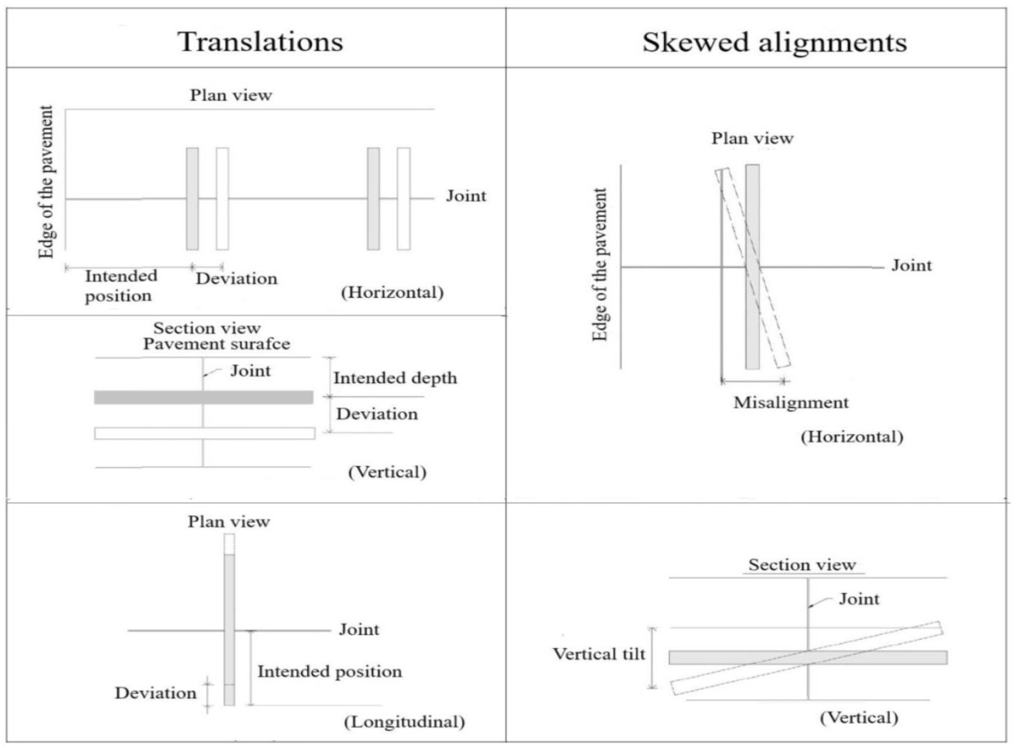
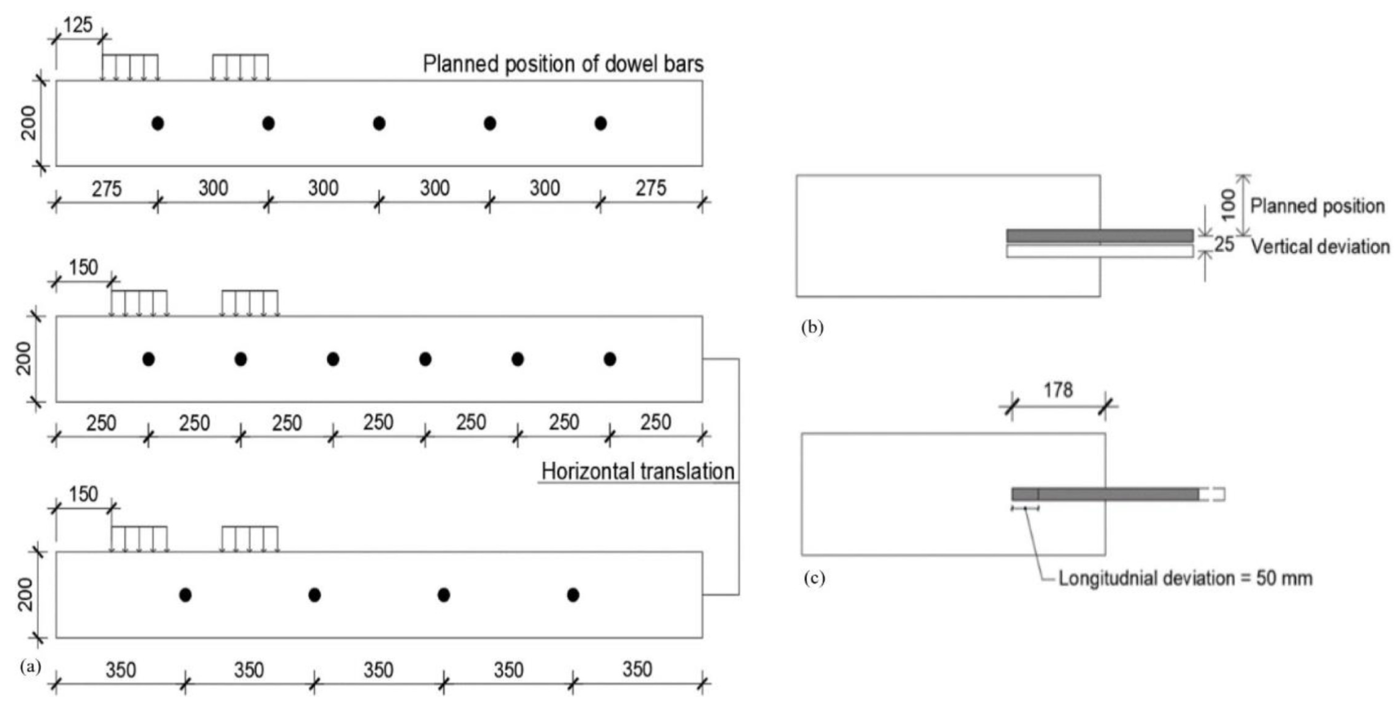
  • Lateral or horizontal translation: When the dowel bar is located far enough from its specified position, this is defined as horizontal translation [16].
  • Depth deviation or vertical translation: Depth deviation indicates the elevation difference between the dowel bar’s planned position and its actual placement within the concrete slab [16,17].
  • Longitudinal translation: If the dowel bar centroid does not match with the transverse joint, this is referred to as longitudinal translation [18].
  • Horizontal or vertical skew: The rotation of the dowel bar in a horizontal plane relative to the pavement centreline is known as horizontal skew. Conversely, vertical tilt is the rotation of the dowel bar in a vertical plane relative to the pavement surface [17].
Figure 1. Load transfer mechanism in JPCP including joints with and without the dowel bar (Reproduced with permission of Transportation Research Record from [19]).
Buildings 14 01039 g001
Figure 2. Schematic view of different types of dowel bar mislocation (Reproduced with permission of the Transportation Research Board from [20]).
Buildings 14 01039 g002
The performance of the JPCP depends on several factors including the thickness of the concrete slab; the strength of the concrete slab, base, subbase and subgrade; the surrounding temperature; the number and size of the vehicle; the transverse joint spacing; the joint width; and the dowel bars’ diameter and spacing [21,22]. Numerous studies have been conducted to enhance the performance of the JPCP system. Mackiewicz (2015) studied the stress concentration around the dowel bar and determined the efficiency of interaction between the loaded and unloaded slab depending on the dowel bar parameters, i.e., diameter, spacing, and length. The findings indicated that dowel parameters substantially influenced the vertical compressive stresses in the concrete slab [23,24]. Khazanovic et al. (2009) performed a laboratory test considering various embedment lengths, ranging from 51 mm to 229 mm [2 in. to 9 in.]. The results indicated that increasing the embedment length enhanced the shear capacity of the dowel bar [25].
Odden et al. (2003) performed a full-scale test to examine the influence of concrete cover resulting from vertical deviation of the dowel bar. Two different dowel bar configurations were considered. In the first arrangement, the dowel bars were placed at the mid-depth of 190 mm [7.5 in.] of a thick concrete slab with a 76 mm [3 in.] concrete cover, while in the second arrangement, the dowel bars were set with a 51 mm [2 in.] cover. It was found that reducing the concrete cover slightly lowered the LTE and increased the dowel looseness [26]. Furthermore, Khazanovic et al. (2009) proposed that a concrete cover greater than 3.5× diameter of the dowel bar does not contribute significantly to the shear capacity [25].
Shoukry (2002) conducted a numerical study to compute contact stress around the dowel bar by comparing the modified dowel design with the conventional dowel bar. The modified dowel design included adding two steel sleeves at the mid-length of the dowel bar while the sleeves were spaced 25–30 mm apart. The outer surface of the sleeves was directly in contact with the concrete slab, while the dowel bar could freely slide inside the sleeves. The results revealed that contact stress could be reduced by 52% through utilizing the modified dowel design. Encouraged by the successful demonstration of the new dowel design, highway engineers in West Virginia conducted field tests on Robert C. Byrd’s Highway; for details, see [27]. Table 1 further summarises the important research concerning JPCP, providing a basis for this article.
Although JPCPs are recognized for their longevity, they constitute less than one percent of the total highway network in Sweden [43,44]. This limited adoption is attributed to the experience with existing concrete pavements, which is mixed. The most recent JPCP was constructed 18 years ago in Uppsala and showed extensive rutting earlier than was anticipated. Another contributing factor to the scarcity is the potential for major deterioration, which is a concern for the Swedish Transport Administration (Trafikverket) due to the time-consuming repair process, including lengthy lane closures, necessitating circuitous routes and disruption for road users [45]. Precast concrete slabs can be installed overnight [46], but their performance relies on the well-functioning dowel bar [47,48].
Furthermore, the literature on precast concrete technology demonstrates variations in the placement of dowel bars, i.e., at the concrete slab’s top, bottom, and mid-height [49,50]. However, the dowel bar position is crucial for ensuring the adequate performance of the pavement system. Despite several research studies being conducted over the past decades, the JPCP still requires further investigation to enhance the structural performance of the pavement system and thereby increase the service life. This is particularly important in Sweden, where research on concrete roads is relatively limited. This paper examined the structural response of JPCP through a parametric study of the dowel bar using numerical simulation with finite element software (ABAQUS) based on Swedish concrete pavement design.

2. Aims and Objectives

The aim of the paper is to investigate the structural behaviour of JPCP based on the dowel-related parameters using a three-dimensional finite element model (3D-FEM). The 3D model was developed using Abaqus software and was compared with the analytical solution, i.e., the Westergaard method. Subsequently, dowel bars were introduced in the model to analyse the load transfer capacity. The objectives of the study were as follows:
Evaluate the effect of different positions of the dowel bar (at the top, bottom, and mid-height of the concrete slab) on LTE and flexural stress in the concrete slab;
Identify the influence of the joint opening on the LTE;
Identify the effect of mislocation of the dowel bar (horizontal, vertical, and longitudinal translations) on the LTE;
Examine the influence of the dowel bar diameter on the LTE;
Analyse the impact of the bond between the concrete slab and the dowel bar on the LTE.

3. Westergaard Method

In 1926, the Danish-American H.M. Westergaard developed a technique to determine the stresses and deflections due to single wheel load in concrete pavements. This method assumed that an infinite, thin concrete slab rests on an elastic foundation and that the concrete slab and subgrade are always in full contact. Furthermore, a circular contact area is assumed for wheel load [51,52]. Later, these equations were modified by Teller, Sutherland, Kelly, and Eisenmann [53,54,55,56,57]. The derived equations are available for three critical loading conditions, i.e., interior, edge, and corner loading; see Figure 3. The following stress and deflection equations are cited in [57,58,59], respectively.
Stress and deflection equations for interior loading
σ centre = 0.275 ( 1 + ν ) F h c 2 log E c h c 3 k b 4 0.436 w 0 m = F 8 k l 2 w centre = w 0 m 1 + 0.3665 log a l 0.2174 a l 2
Stress and deflection equations for edge loading
σ edge = 0.529 ( 1 + 0.54 ν ) F h c 2 log E c h c 3 k b 4 + log b 1 ν 2 2.484 w edge = 1 6 1 + 0.4 ν F k l 2
Stress and deflection equations for corner loading
σ corner = 3 F h c 2 1 12 ( 1 ν 2 ) k E c h c 3 0.3 ( 2 a ) 1.2 w corner = 1.1 0.88 α l F k l 2
  • where,
l = E c h c 3 12 ( 1 ν 2 ) k 0.25 k = E u ( h 1 * ) 2 1 h * h b h 2 * 1 h * 1 h 1 * h 1 * = 0.83 h c E c E u 3 h 2 * = 0.9 h b E b E u 3 h * = h 1 * + h 2 *
b = 1.6 a 2 + h c 2 0.675 h c for a < 1.724 h c a for a > 1.724 h c
F = point load (N)
h c = slab thickness (mm)
h b = base layer thickness (mm)
a = radius of the loaded circular surface (mm)
b = derived length parameter (mm)
ν = Poisson’s ratio (−)
l = radius of relative stiffness (mm)
α = distance of the load from the corner (mm)
E c = modulus of elasticity of concrete (MPa)
E b = modulus of elasticity of the base (MPa)
E u = modulus of elasticity of subgrade (MPa)
k = modulus of subgrade reaction (N/mm3)

4. Development of a 3D Finite Element Model

ABAQUS is the product of two main analyses, i.e., ABAQUS/Standard and ABAQUS/ Explicit. ABAQUS/Standard is a general-purpose program that can be used for both linear and nonlinear problems, while ABAQUS/Explicit is a special-purpose analysis that is suitable for dynamic events such as impact and blast problems and is also efficient for highly nonlinear problems [60]. In this study, ABAQUS/Standard was used to develop a finite element model due to the static nature of the applied load.

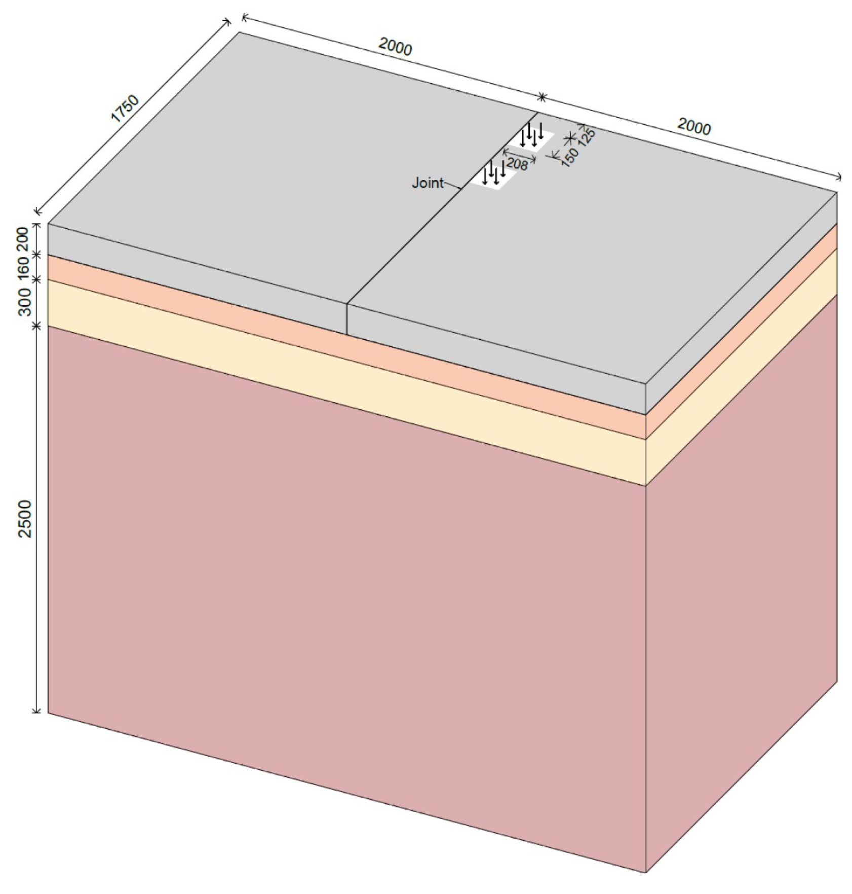
4.1. Geometry and Loads

The developed FE model consists of concrete slabs supported by the base, subbase, and subgrade. The slabs of Swedish jointed plain concrete pavements are 5 m long with a lane width of 3.5 m [61]. In this study, concrete slabs were modelled with 2 m × 1.75 m dimensions. This size reduction was intended to enhance computational efficiency and simplify the model, as the study primarily focused on analysing local stresses and deformations. The size reduction would hardly influence local behaviours close to the dowel bar. Although a finer mesh would provide more accurate results, it would also require more computational time than would a coarser mesh due to the greater number of mesh elements. Therefore, reducing the model’s size is a practical approach to balancing computational efficiency with accuracy in the FE solution.
The slab, base, and subbase thicknesses were 200 mm, 160 mm, and 300 mm (including 80 mm of the unbounded road base), respectively [45,62]. The subgrade layer was extended to 2500 mm to approximate it as an infinite foundation. The joint width between adjacent slabs was considered 2 mm. The abutting slabs were connected by a steel dowel bar. The steel dowel bars were 32 mm in diameter and 358 mm in length and were placed at the mid-depth of the concrete slab with 300 mm centre-to-centre spacing. The standard axle (a single axle with dual wheels on each side) with 10 metric tons was considered for vehicle load [59]. The single wheel load in the standard axle was 25 kN with a tire pressure of 800 kPa. The dual-wheel loads were modelled on a small rectangular plate, i.e., 150 mm × 208 mm and were 125 mm away from the edge of the loaded slab. A three-dimensional view of the JPCP is shown in Figure 4.

4.2. Material Properties

Isotropic elastic materials are considered for concrete slabs, base, subbase, subgrade, and steel dowel bars. The concrete strength class was assumed to be C40/50, and the base property was selected from [59], while the properties of subbase and subgrade were chosen from [63]. The materials’ properties are presented in Table 2.

4.3. Interactions

The tangential behaviour between the concrete slab and base, base and subbase, and subbase and subgrade was modelled using the Coulomb friction model, which considers frictional behaviour in terms of the coefficient of friction acting to oppose relative motion between contacting surfaces. In addition, normal hard contact was modelled to allow for the separation between the different surfaces. The interaction between the surfaces was modelled by considering the surface-to-surface contact [64]. The coefficients of friction between the concrete slab and base, base and subbase, and subbase and subgrade were all considered 1.0. The interaction between the dowel bar and the concrete slab was also developed using the Columb friction model. The interface between half of the dowel bar and the concrete slab was modelled as a perfect bond (i.e., ungreased dowel bar), while the other half interface between the dowel bar and the adjacent concrete slab was modelled in a way that allowed for the longitudinal movement of the dowel bar (i.e., greased dowel bar). Therefore, the coefficient of friction for the perfect bonded side was assumed to be 1.0, and for the greased dowel bar, was assumed to be 0.05 (no data are available in the literature). The separation between the interfaces was facilitated using hard contact model behaviour that considered surface-to-surface contact.

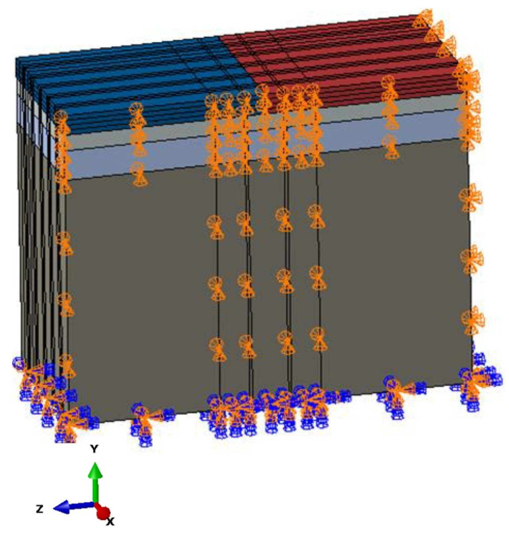
4.4. Boundary Conditions

The connection between the steel dowel bar and the concrete slab solely depends on the interaction properties. However, all degrees of freedom are constrained at the bottom of the subgrade, whereas the sides of the concrete slab, base, subbase, and subgrade are restrained in the vertical direction (i.e., Y-direction) and the respective degree-of-freedom direction. These boundary conditions were implemented by comparing the FE model with the analytical solution. The boundary condition of the 3D model is presented in Figure 5.

4.5. Meshing

All model parts were meshed using eight-noded continuum three-dimensional brick elements (C3D8Rs) with reduced integration and hourglass control. The FE model uses more nodes in full integration, enhancing the element’s stiffness. Therefore, reduced integration was chosen, as it accounts for fewer nodes, which, on the other hand, might exaggerate the deflection. However, to mitigate this potential issue, hourglass control was implemented. Additionally, the area around the dowel bar and the proximity of the applied load are critical stress zones, and thus the model was divided into different parts using the partition tool, and a finer mesh was applied in these regions. The model contains a total of 207,800 elements. Figure 6 illustrates the mesh density around the dowel bar.

5. Results and Discussion

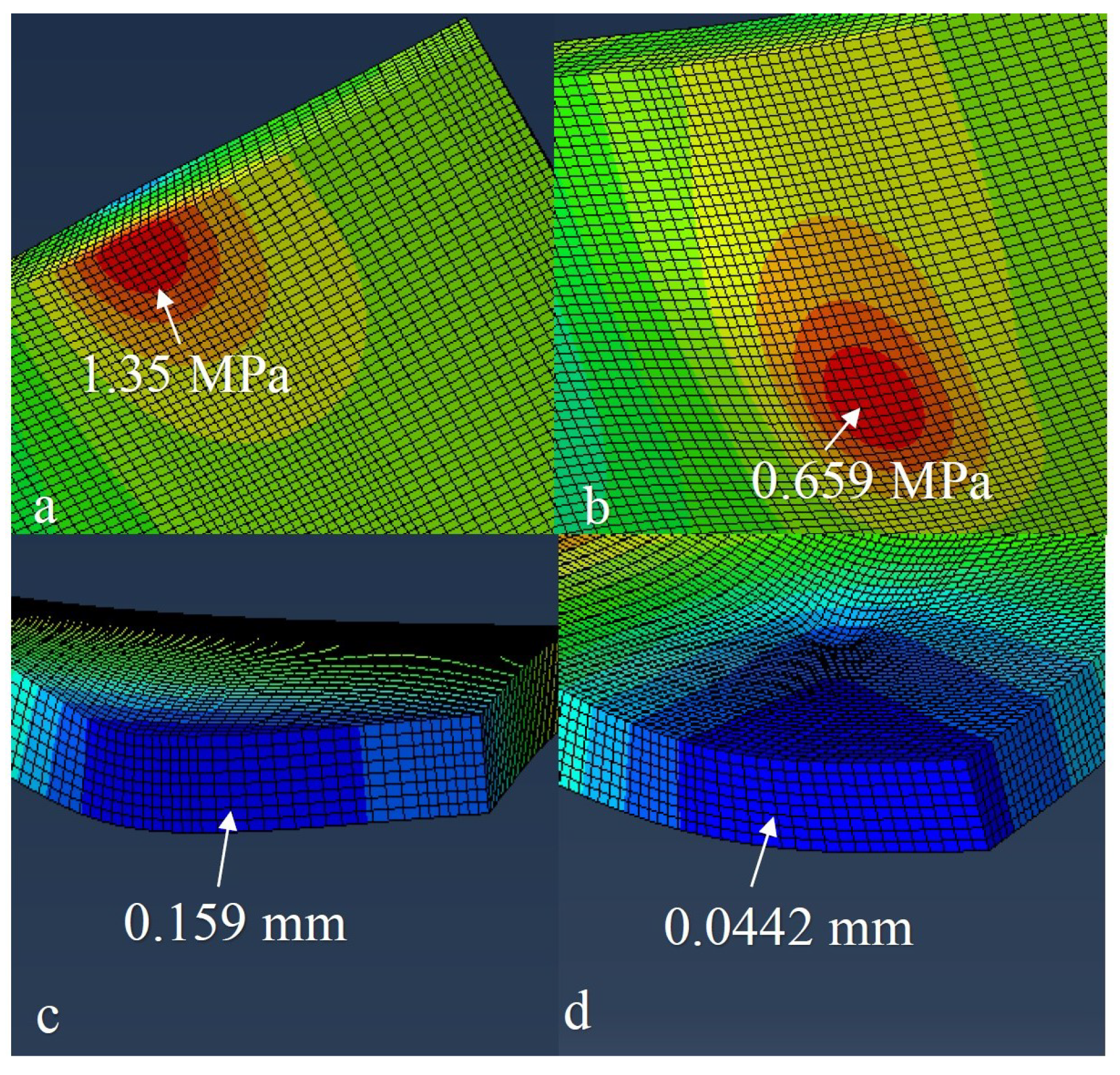
5.1. Comparison of the FE Model with the Westergaard Method

The FE model was checked by comparing the results of computational solutions with the Westergaard method for interior, edge, and corner loadings. The stress and deflection results of different loading conditions are presented in Table 3. It was observed that the difference in the stress values between the computational and analytical solutions ranged between 8 and 60%, while the values of deflection ranged between 28 and 35%. Figure 7 illustrates the locations where stress and deflection were analysed for both interior and edge loading, as acquired from the finite element (FE) analysis.
The difference in the values between the ABAQUS and analytical solution could have been due to the Westergaard method accounting the circular wheel loading and infinite extension of the concrete slab. Furthermore, the Westergaard method considers the deflection beneath the applied load. In reality, the area outside the load within the boundary of the concrete slab also contributes to the deflection [64,65]. However, it was also noted that the Westergaard solution provided fairly good results for interior and edge loading while overestimating the stress for corner loading.

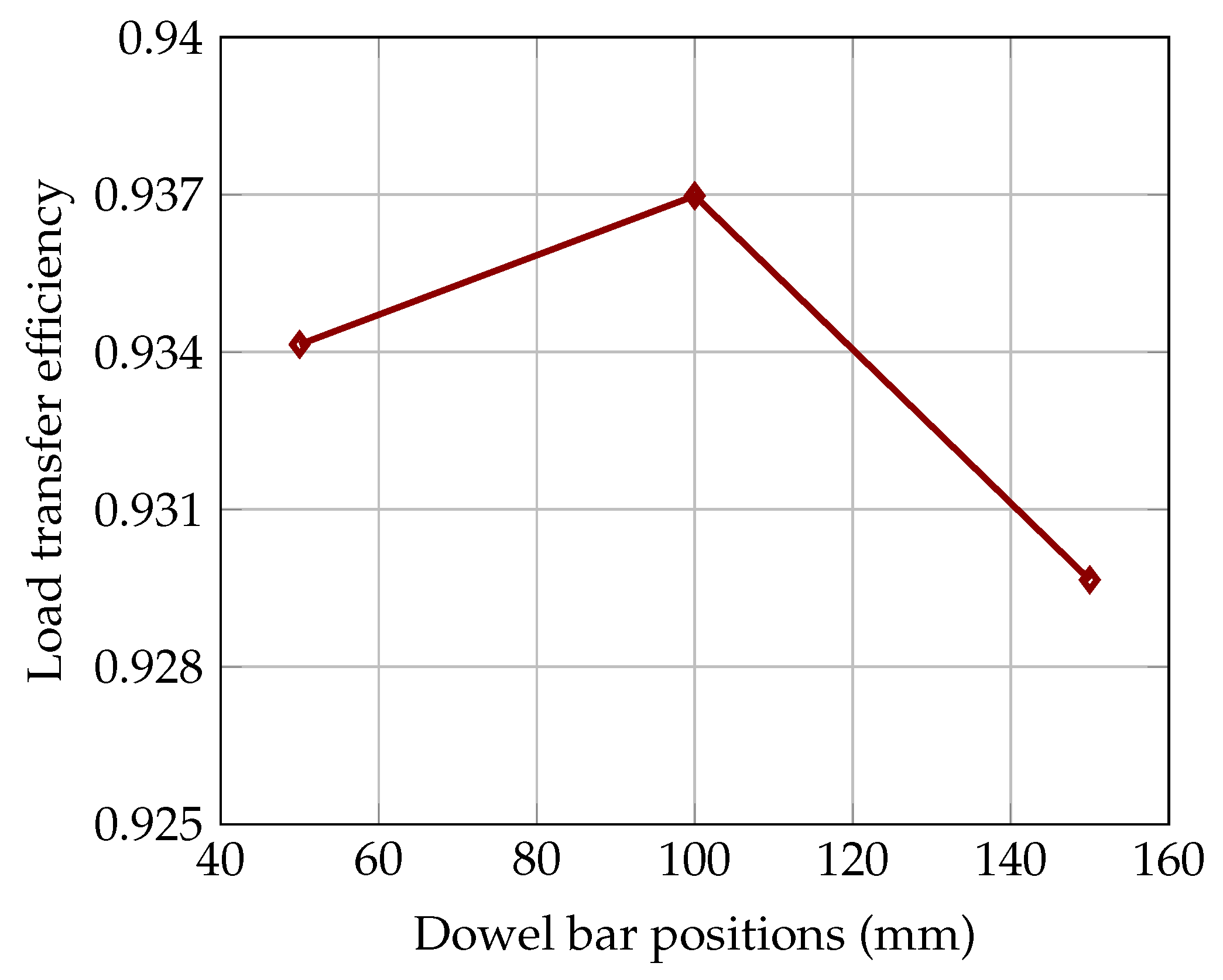
5.2. The Effect of Dowel Bar Position on the Load Transfer Efficiency

The appropriate position of the dowel bar is a critical factor in preventing transverse joint faulting, as it negatively affects ride smoothness and significantly impacts the durability. This section analysed the structural performance of concrete pavement by considering the dowel bar at the concrete slab’s top, bottom, and mid-height. In addition, the flexural stress in the concrete slab was also evaluated for these positions of the dowel bar. The deflection values of the loaded and unloaded slabs and the flexural stress in the loaded concrete slab are shown in Table 4, while the LTE for each dowel position is presented in Figure 8.
Figure 8 shows that the maximum LTE was achieved when the dowel bar was at the mid-depth of the concrete slab. Furthermore, noticeable variations in LTE existed for the dowel bar at different locations, although these differences were small. It is also important to note that dowel bar slots located at the top of the slab increased the exposure of the grout, potentially causing roughness and loose materials on the pavement surface. It is worth mentioning that good slot materials that are properly installed should not deteriorate. However, construction problems can occur, and placing the slots at the centre or bottom of the concrete slab reduces the load and environmental effects on the dowel grouting material. A lower value of flexural stress was observed when the dowel bar was at the top height of the concrete slab. In contrast, higher flexural stress developed when the dowel bar was placed at the bottom height of the concrete slab. This disparity can be attributed to the dowel bar at the bottom height being farther away from the applied load. Consequently, the dowel bar was less effective at this position in supporting flexural stress than when placed at top height of the concrete slab.

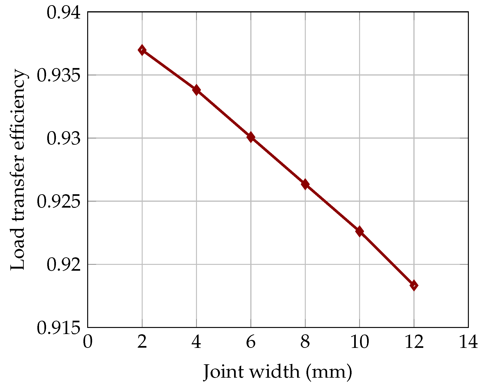
5.3. The Effect of Joint Opening on the Load Transfer Efficiency

The concrete slabs contract and joints open when subjected to low temperatures. This section presents the evaluation of the effect of joint opening on dowel bar LTE. The deflection values of loaded and unloaded slabs for different joint widths, i.e., 2 mm, 4 mm, 6 mm, 8 mm, 10 mm, and 12 mm, are presented in Table 5, and the LTE is shown in Figure 9. It can be seen in Figure 9 that the joint width had a significant impact on the LTE; with increasing joint width, the LTE decreases. In reality, aggregate interlock also contributes to the LTE for small joint openings. In precast concrete pavement, joint openings are typically variable and wider than are those in cast-in-place pavement, which maintains uniform narrow widths. The potential variation in the joints of precast concrete pavement may be affected by the precise cut of the damaged slab and the accurate installation of the precast slab. Moreover, wider joint openings demand more sealant materials to maintain the integrity of the pavement structure, and wider sealant materials may face challenges in terms of durability due to increased exposure to traffic and environmental loads. Therefore, recognizing the role of the joint opening is paramount to ensuring the sustained performance and longevity of the pavement system.

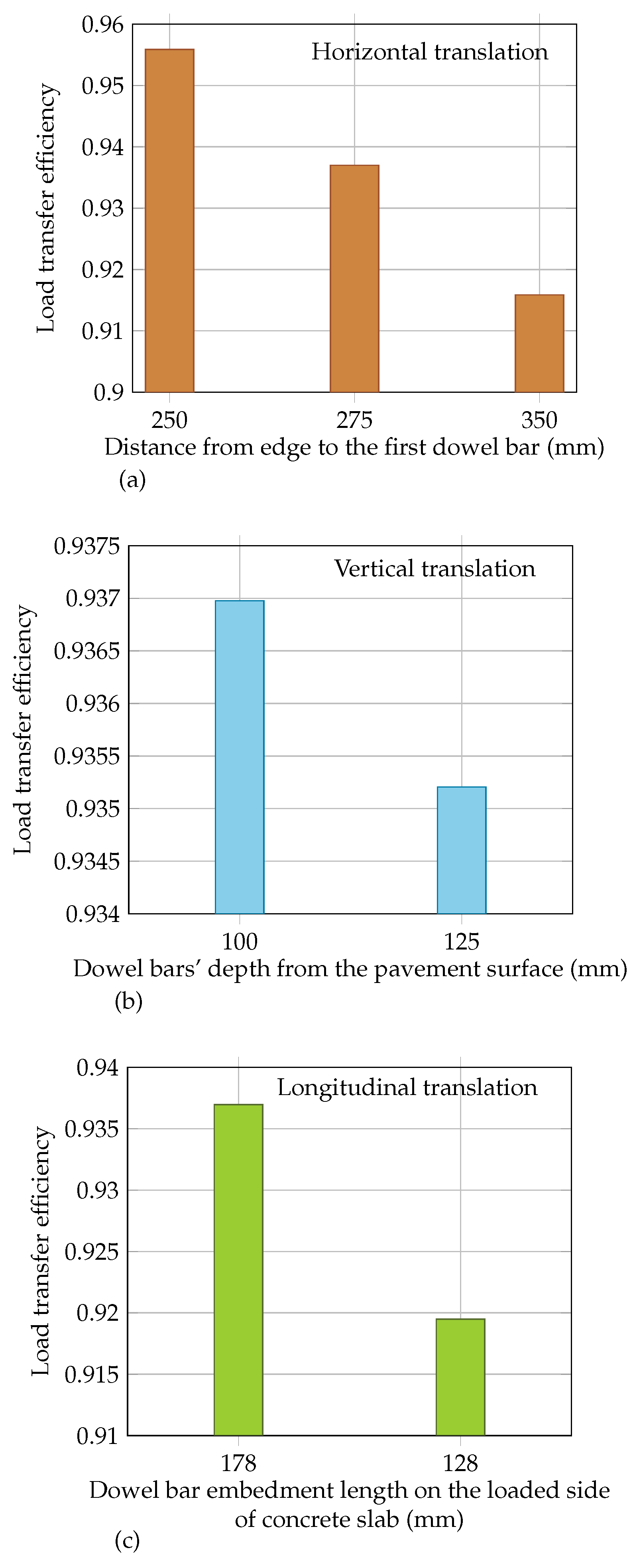
5.4. The Effect of the Mislocation of Dowel Bar on the Load Transfer Efficiency

This section outlines the analyses of the LTE, which included consideration of the dowel bar’s horizontal, vertical, and longitudinal translations; see Figure 10. The horizontal translation of the dowel bar was examined when the dowel bar was located close (i.e., 250 mm from the corner) and far (i.e., 350 mm from the corner) from its intended position (i.e., 275 mm from the corner). In the case of horizontal translation, it can be seen in Figure 10a that the applied load was further moved at 25 mm from the original position (i.e., 125 from the edge) to avoid complexity in the model. The vertical translation was evaluated when the dowel bar’s depth deviated 25 mm from its intended position (vertical depth 100 mm); see Figure 10b. The longitudinal translation was analysed when the dowel bar centroid was 50 mm away from the transverse joint, see Figure 10c. The deflection values of loaded and unloaded slabs for each translation are presented in Table 6, Table 7 and Table 8, and their corresponding LTE is illustrated in Figure 11.
Figure 11 demonstrates the influence of deviation of the dowel bar from its planned position on LTE. Figure 11a reveals that the proximity of the dowel bar to the corner enhances LTE, while the distant placement of the dowel bar from its planned position decreases LTE. Figure 11b,c shows that the deviation of the vertical depth and longitudinal translation of the dowel bar noticeably decreases the LTE. Additionally, improper vertical positioning may compromise the concrete cover, leading to potential corrosion of the dowel bar and resulting in concrete spalling or cracking. Moreover, deviation of the dowel bar centroid from the joint may result in higher bearing stresses, potentially causing concrete cracking and faulting. These findings underscore the importance of precise dowel bar placement for optimal load transfer and structural integrity.

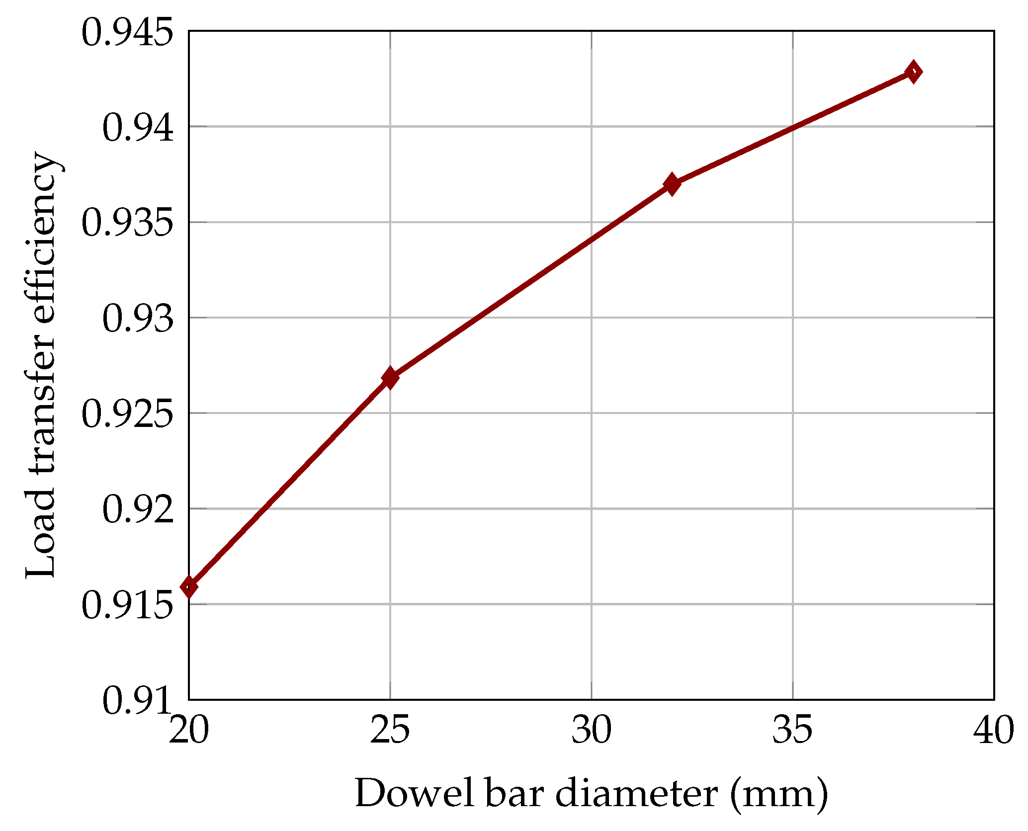
5.5. The Effect of Dowel Bar Diameter on the Load Transfer Efficiency

This section describes the assessment of the structural performance of concrete pavement with various diameters of dowel bars, including 20 mm, 25 mm, 32 mm, and 38 mm. The deflection values of the loaded and unloaded concrete slabs are presented in Table 9, and the corresponding LTE is illustrated in Figure 12. It can be seen in Figure 12 that the dowel’s diameter significantly contributes to enhancing the LTE. This is because the cross-sectional area of the dowel bar increases with the diameter, ultimately reducing bearing stress and increasing joint stiffness. Therefore, the adequate size of the dowel bar is a critical factor in the overall concrete pavement design to avoid anticipated distresses such as corner cracking, faulting, and pumping.

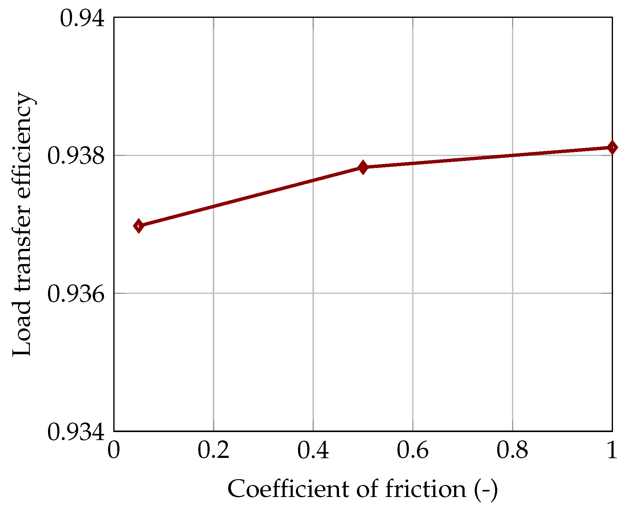
5.6. The Effect of Bonding between the Concrete Slab and Dowel Bar on Load Transfer Efficiency

This section described the examination of the influence of the bond between the concrete slab and dowel bar on LTE based on the coefficient of friction. Half of the interface was assumed to be perfectly bonded, simulating an ungreased dowel bar with a corresponding coefficient of friction of 1.0. Conversely, the other half of the interface exhibited varying bond strengths, resulting in a range of friction coefficients, i.e., 0.05, 0.5, and 1.0. The deflection values of the loaded and unloaded slabs are shown in Table 10, and the corresponding LTE is presented in Figure 13.
Figure 13 illustrates that the bond at the interface of the concrete slab and dowel bar had a minor effect on LTE. However, Khazanovic et al. (2009) conducted research on the 152 mm embedded dowel bar, and the results demonstrated that greasing the dowel bar reduces the force required for pull-out failure, while an ungreased dowel bar requires a greater force. It is important to note that a higher pull-out force for an ungreased dowel bar may lead to increased resistance against the movement, which could potentially restrict the dowel bar’s ability to accommodate the expansion and contraction of the slab due to temperature variations and concrete shrinkage in new construction. Consequently, such restriction in movement may affect the overall performance and durability of the pavement system.

6. Conclusions

The dowel bar is an essential parameter of the jointed plain concrete pavement system as it provides structural support to the pavement at the joints without restricting the joints opening and closing due to shrinkage and temperature variations. The key function of the dowel bar is to transfer the applied load across the joint. In this study, a finite element model was developed to investigate the interaction between adjacent slabs in terms of LTE due to dowel-related parameters. The FE model was compared with the analytical solution. The following conclusions could be drawn from the numerical simulations:
  • The results demonstrate that the maximum LTE is accomplished when the dowel bar is placed at the mid-height of the concrete slab. In addition, higher flexural stress develops in the concrete slab when the dowel bar is located at the bottom height of the concrete slab.
  • During winter, the joints open as the concrete slab contracts, potentially causing issues in transferring wheel loads. This study observed a 2.1% reduction in LTE as the joint width increased from 2 mm to 12 mm. Conversely, the LTE improved by 3% with an increase in the diameter of the dowel bar. The dowel bar diameters considered in this study were 20 mm, 25 mm, 32 mm, and 38 mm.
  • The study shows that the mislocation of the dowel bar (i.e., horizontal, vertical, and longitudinal translations) has a minimal impact on LTE. An approximate 2.1% difference in LTE was noted for horizontal and longitudinal translations of the dowel bar, while for vertical translation, the reduction in load transfer was around 0.5%. However, a marginal increase in LTE of approximately 0.5% was observed with an increased bond at the interface of the concrete slab and the dowel bar.
The findings of this study provide new knowledge that can be used for ensuring the effectiveness of dowel load transfer systems in jointed plain concrete pavement. Given the substantial anticipated loads during the pavement’s service life, the impact of the investigated parameters is significant. Therefore, careful attention to factors such as joint width, dowel bar placement, diameter, and dowel bar deviation from its intended position is essential for optimizing pavement’s structural and functional performance, as well as its durability. Prioritizing durability not only leads to lower maintenance costs but also allows transportation agencies to effectively manage infrastructure budgets and improve overall road network efficiency.

7. Future Research

The structural performance of jointed plain concrete pavement can be improved by reducing the bearing stresses at the interface between the concrete and dowel bar. This can be done using non-rounded dowel bars (such as elliptical and plate dowels) and corrosion-resistant materials (such as stainless steel and glass fibre-reinforced polymer dowels). For this, experimental tests can be conducted to assess the structural capacity of the non-rounded dowel bars and the dowel bars fabricated from different materials, with the results being compared with the those of a rounded steel dowel bar of a similar cross-sectional area. Furthermore, this study did not include the effect of skewed dowels on pavement performance, which can be investigated in future research.

Author Contributions

S.Y.: conceptualization, methodology, formal analysis, and writing—original draft preparation, review, and editing. J.S. and R.G.R.B.: validation and writing—review and editing. All authors have read and agreed to the published version of the manuscript.

Funding

This work is financially supported by the Swedish Transport Agency (Trafikverket).

Data Availability Statement

All datasets presented in this study are included in the article.

Conflicts of Interest

The authors declare no conflicts of interest.

References

  1. Maitra, S.R.; Reddy, K.S.; Ramachandra, L.S. Load transfer characteristics of aggregate interlocking in concrete pavement. J. Transp. Eng. 2010, 3, 190–195. [Google Scholar] [CrossRef]
  2. Delatte, N. Concrete Pavement Design, Construction, and Performance; Taylor & Francis: Abingdon, UK; New York, NY, USA, 2008; pp. 25–27. [Google Scholar]
  3. Guo, H.; Sherwood, J.A.; Snyder, M.B. Component dowel-bar model for load-transfer systems in PCC pavement. J. Transp. Eng. 1995, 121, 289–298. [Google Scholar] [CrossRef]
  4. Snyder, M. Guide to Dowel Load Transfer Systems for Jointed Concrete Roadway Pavements; Institute for Transportation: Ames, IA, USA, 2011. [Google Scholar]
  5. Yaqoob, S.; Silfwerbrand, J.; Strömberg, L. Evaluation of rapid repair of concrete pavements using precast concrete technology: A sustainable and cost-effective solution. Nord. Concr. Res. 2021, 65, 107–128. [Google Scholar] [CrossRef]
  6. Tayabji, S. FHWA Project R05 IAP Funded Project Case Study: Honolulu Interstate H1 Precast Concrete Pavement Demonstration Project; Federal Highway Administration (FHWA): Washington, DC, USA, 2016. [Google Scholar]
  7. Tayabji, S. FHWA Project R05 IAP Funded Project Case Study: Mobile Ramp Precast Concrete Pavement Demonstration Project; Federal Highway Administration (FHWA): Washington, DC, USA, 2017. [Google Scholar]
  8. Federal Highway Administration. Concrete Pavement Joints (Technical Advisory, T 5040.30); Federal Highway Administration: Washington, DC, USA, 2019.
  9. Tayabji, S. Guide Specification for Jointed Precast Concrete Pavement: [techbrief]; Federal Highway Administration: Washington, DC, USA, 2019. [Google Scholar]
  10. Smith, K.; Harrington, D.; Pierce, L.; Ram, P.; Smith, K. Concrete Pavement Preservation Guide, 2nd ed.; National Concrete Pavement Technology Center: Ames, IA, USA, 2014. [Google Scholar]
  11. ACPA. Dowel Bar Alignment and Location for Placement by Mechanical Dowel Bar Insertion; American Concrete Pavement Association Guide Specification: Skokie, IL, USA, 2013. [Google Scholar]
  12. Sturges, T.; Frankhouser, A.; Abbas, A.R. Evaluation of dowel bar alignment from a two-step dowel bar inserter. Int. J. Pavement Eng. 2014, 15, 438–448. [Google Scholar] [CrossRef]
  13. Khaki, A.M.; Azadravesh, E. Generating a 3D model for evaluating the joint opening effects on load transfer efficiency in concrete pavements, using Abaqus. In Proceedings of the 5th National Congress on Civil Engineering, Mashhad, Iran, 4–6 May 2010. [Google Scholar]
  14. Shoukry, S.N.; William, G.W.; Riad, M.Y. Evaluation of Load Transfer Efficiency Measurement; West Virginia University, Department of Civil and Environmental Engineering: Morgantown, WV, USA, 2005. [Google Scholar]
  15. Yu, H.T.; Tayabji, S. Best practices for Dowel Placement Tolerances; Federal Highway Administration: Washington, DC, USA, 2007. [Google Scholar]
  16. ACPA. Dowel Bar Alignment and Location; American Concrete Pavement Association Guide specification: Rosemont, IL, USA, 2018. [Google Scholar]
  17. ACPA. Evaluating and Optimizing Dowel Bar Alignment; American Concrete Pavement Association Guide specification: Rosemont, IL, USA, 2006. [Google Scholar]
  18. Kivi, A.K. Dowel bar alignment in concrete pavements—21st century standards and methods. In Proceedings of the Transportation Association of Canada 2020 Conference and Exhibition—The Journey to Safer Roads, Toronto, ON, Canada, 21 September–8 October 2020. [Google Scholar]
  19. Rao, S.; Hoegh, K.; Yu, T.; Khazanovich, L. Evaluation of dowel alignment constructability in Portland cement concrete pavements. J. Transp. Res. Board 2009, 2098, 86–93. [Google Scholar] [CrossRef]
  20. Tayabji, S. Dowel placement tolerances for concrete pavements. J. Transp. Res. Board. 1986, 10625, 47–54. [Google Scholar]
  21. Rens, L. Guide for the Design of Jointed Plain Concrete Pavements; EUPAVE (European Concrete Paving Association): Brussels, Belgium, 2003. [Google Scholar]
  22. Grosek, J.; Zuzulova, A.; Brezina, I. Effectiveness of Dowels in Concrete Pavement. Materials 2019, 12, 1669. [Google Scholar] [CrossRef] [PubMed]
  23. Mackiewicz, P. Analysis of stresses in concrete pavement under a dowel according to its diameter and load transfer efficiency. Can. J. Civ. Eng. 2015, 42, 845–853. [Google Scholar] [CrossRef]
  24. Mackiewicz, P. Finite-element analysis of stress concentration around dowel bars in jointed plain concrete pavement. J. Transp. Eng. 2015, 141, 1–8. [Google Scholar] [CrossRef]
  25. Khazanovich, L.; Hoegh, K.; Snyder, M. Guidelines for Dowel Alignment in Concrete Pavements; National Cooperative Highway Research Program, Transportation Research Board: Washington, DC, USA, 2009. [Google Scholar]
  26. Odden, T.R.; Snyder, M.; Schultz, A.E. Performance Testing of Experimental Dowel Bar Retrofit Designs, Part 1—Initial Testing; University of Minnesota, Department of Civil Engineering. Transportation Research Board: Minneapolis, MN, USA, 2003. [Google Scholar]
  27. Shoukry, S.N.; William, G.W.; Riad, M. Characteristics of concrete stresses in doweled transverse joints. Int. J. Pavement Eng. 2002, 3, 117–129. [Google Scholar] [CrossRef]
  28. Davids, W.G.; Wang, Z.; Turkiyyah, G.; Mahoney, J.P.; Bush, D. Three-dimensional finite element analysis of jointed plain concrete pavement with EverFE2.2. Transp. Res. Rec. 2003, 1853, 92–99. [Google Scholar] [CrossRef]
  29. Yancong, Z.; Lingling, G. Effect of dowel bar position deviation on joint load-transfer ability of cement concrete pavement. Int. J. Pavement Res. Technol. 2016, 9, 30–36. [Google Scholar]
  30. Shoukry, S.N.; William, G.W.; Riad, M.Y. Motamarri, S.S. Effect of Bonding Force on Stresses in Concrete Slab; West Virginia Department of Transportation: Charleston, WV, USA, 2003. [Google Scholar]
  31. Breeman, W.V. Experimental Dowel Installation in New Jersey. Bull. Highw. Res. Board 1955, 34, 8–33. [Google Scholar]
  32. Mackiewicz, P. Thermal stress analysis of jointed plane in concrete pavements. Appl. Therm. Eng. 2014, 73, 1169–1176. [Google Scholar] [CrossRef]
  33. Maitra, S.R.; Reddy, K.S.; Ramachandra, L.S. Load transfer characteristics of dowel bar system in JPCP. J. Transp. Eng. 2009, 135, 813–821. [Google Scholar] [CrossRef]
  34. Davids, W.G. Effect of dowel looseness on response of jointed concrete pavements. J. Transp. Eng. 2000, 126, 50–57. [Google Scholar] [CrossRef]
  35. Sii, H.W.; Chai, G.W.; Staden, R.V.; Guan, H. Effect of dowel looseness on response of jointed concrete pavements using three-dimensional finite element analysis. Adv. Mater. Res. 2014, 900, 435–444. [Google Scholar] [CrossRef]
  36. Silva, E.R.; Balbo, J.T.; Cargnin, A.P. Effects of dowel bars misalignment in jointed plain concrete pavements—A numerical analysis considering thermal differentials and bonded slab-base interface. IBRACON Struct. Mater. J. 2021, 14, 1–14. [Google Scholar] [CrossRef]
  37. Kim, K.; Chun, S.; Han, S.; Tia, M. Effect of dowel bar arrangements on performance of jointed plain concrete pavement (JPCP). Int. J. Concr. Struct. Mater. 2018, 12, 39. [Google Scholar] [CrossRef]
  38. Nishizawa, T.; Koyanagawa, M.; Takeuchi, Y.; Kimura, M. Study on mechanical behaviour of dowel bar in transverse joint of concrete pavement. In Proceedings of the 7th International Conference on Concrete Pavements, Orlando, FL, USA, 9–13 September 2001. [Google Scholar]
  39. Sadeghi, V.; Hesami, S. Investigation of load transfer efficiency in jointed plain concrete pavements (JPCP) using FEM. Int. J. Pavement Res. Technol. 2018, 11, 245–252. [Google Scholar] [CrossRef]
  40. Sargand, S.M.; Hazen, G.A.; Bazeley, C.C.; Copley, J.R.; George, M.E. Instrumentation of a Rigid Pavement System; Ohio Department of Transportation, Federal Highway Administration: Columbus, OH, USA, 1997. [Google Scholar]
  41. Leong, P.; Tighe, S.; Rothenburg, L.; Hein, D. Finite difference modelling of misaligned dowel bars and their effects on joint performance. Transp. Res. Rec. 2006, 1946, 101–110. [Google Scholar] [CrossRef]
  42. Prabhu, M.; Varma, A.H.; Buch, N. Experimental and analytical investigation of mechanistic effects of dowel misalignment in jointed concrete pavements. Transp. Res. Rec. 2007, 2037, 12–29. [Google Scholar] [CrossRef]
  43. Strömberg, L.; Silfwerbrand, J.; Ansell, A.; Hintze, S. Making concrete pavements competitive by using the standardised framework for comparisons of Infrastructure projects in terms of cost-efficiency and climate impact. Nord. Concr. Res. 2020, 62, 21–39. [Google Scholar] [CrossRef]
  44. Yaqoob, S. Concrete Pavements’ Repair Techniques and Numerical Assessment of Dowel Bar Load Transfer Efficiency. Licentiate Thesis, KTH Royal Institute of Technology, Stockholm, Sweden, 2024. [Google Scholar]
  45. Silfwerbrand, J. Concrete pavements for modern Swedish highways. In Proceedings of the 14th International Symposium on Concrete Roads, Krakow, Poland, 25–28 June 2023. [Google Scholar]
  46. Yaqoob, S.; Silfwerbrand, J. Rapid repair of concrete pavement using precast technology. In Proceedings of the 14th International Symposium on Concrete Roads, Krakow, Poland, 25–28 June 2023. [Google Scholar]
  47. Tayabji, S. Precast Concrete Pavement Technology Implementation; Federal Highway Administration (FHWA): Washington, DC, USA, 2019. [Google Scholar]
  48. Tayabji, S. Load Transfer Systems for Jointed Precast Concrete Pavement: [techbrief]; Federal Highway Administration (FHWA): Washington, DC, USA, 2015. [Google Scholar]
  49. Smith, P.; Snyder, M. Manual for Jointed Precast Concrete Pavement, 3rd ed.; National Precast Concrete Association (NPCA): Washington, DC, USA, 2019. [Google Scholar]
  50. Pierce, L.M.; Weston, J.; Uhlmeyer, J.S. Dowel Bar Retrofit-Do’s and Don’ts; Washington (State). Department of Transportation—Office of Research and Library Services: Olympia, WA, USA, 2009. [Google Scholar]
  51. Dhawale, A.W.; Vishwanath, M. Comparative study of wheel load stress and warping stress on concrete pavements. Int. J. Civil Struct. Environ. Infrastruct. Eng. Res. Dev. (IJCSEIERD) 2014, 4, 9–14. [Google Scholar]
  52. Westergaard, H.M. Stresses in Concrete Pavements Computed by Theoretical Analysis. Public Roads 1926, 7, 25–35. [Google Scholar]
  53. Teller, L.W.; Sutherland, E.C. The structural design of concrete pavements, Part 3—A case study of concrete pavement cross sections. Public Roads 1935, 16, 45–65. [Google Scholar]
  54. Teller, L.W.; Sutherland, E.C. The structural design of concrete pavements, Part 4—A study of the structural action of several types of transverse and longitudinal joint designs. Public Roads 1936, 17, 67–114. [Google Scholar]
  55. Teller, L.W.; Sutherland, E.C. The structural design of concrete pavements, Part 5—Experimental study of the Westergaard analysis of stress conditions in concrete pavement slabs of uniform thickness. Public Roads 1943, 23, 115–160. [Google Scholar]
  56. Kelley, E.F. Application of the research results to the structural design of concrete pavements. Public Roads 1939, 20. [Google Scholar]
  57. Eisenmann, J. Betonfahrbahnen. Handbuch für Beton-, Stahlbeton-und Spannbetonbau; Verlag von Wilhelm Ernst & Sohn: Berlin, Germany; München, Germany; Düsseldorf, Germany, 1979. [Google Scholar]
  58. Petersson, Ö. Svensk Metod för Dimensionering av Betongvägar; Licentiatavhandlig, Kungl Tekniska Högsklan Institutioen för Byggkonstruktion: Stockholm, Sweden, 1996. [Google Scholar]
  59. Silfwerbrand, J. Dimensionering av Betongbeläggningar, (Design of Concrete Pavements); KTH Royal Institute of Technology, Department of Structural Mechanics and Engineering: Stockholm, Sweden, 1995. [Google Scholar]
  60. Dassault Systems. Simulia User Assistance 2021. Available online: https://www.3ds.com/support/documentation/user-guides (accessed on 14 January 2024).
  61. AB Svensk Byggtjänst. Betong på Mark (Handbok) (Concrete slabs on grade [Handbook]); AB Svensk Byggtjänst: Stockholm, Sweden, 2002; p. 253. (In Swedish) [Google Scholar]
  62. STA. ATBVÄG: Allmän Teknisk Beskrivning för vä Gkonstruktioner; Swedish Transport Administration: Stockholm, Sweden, 2003. (In Swedish)
  63. Chen, F.; Balieu, R.; Kringos, N. Thermodynamics-based finite strain viscoelastic-viscoplastic model coupled with damage for asphalt material. Int. J. Solids Struct. 2016, 129, 61–73. [Google Scholar] [CrossRef]
  64. El-Matty, A.E.A.; Hekal, G.M.; El-Din, E.M.S. Modeling of dowel jointed rigid airfield pavement under thermal gradients and dynamic loads. Civ. Eng. J. 2016, 2, 38–51. [Google Scholar] [CrossRef]
  65. Caliendo, C.; Parisi, A. Application of the results of research to the structural design of concrete pavements. J. Transp. Eng. 2010, 136, 664–667. [Google Scholar] [CrossRef]
Figure 3. Different loading conditions. (a) Corner loading. (b) Edge loading. (c) Interior loading.
Buildings 14 01039 g003
Figure 4. Three-dimensional view of the model (all dimensions are in mm).
Buildings 14 01039 g004
Figure 5. Boundary conditions in the 3D FE model.
Buildings 14 01039 g005
Figure 6. Mesh details around the dowel bar.
Buildings 14 01039 g006
Figure 7. FE stress and deflection locations for different loading conditions. (a,c) Edge loading. (b,d) Interior loading.
Buildings 14 01039 g007
Figure 8. Impact of dowel bar’s position on the load transfer efficiency.
Buildings 14 01039 g008
Figure 9. Impact of joint width on the load transfer efficiency.
Buildings 14 01039 g009
Figure 10. Dowel bars location in the FE model for considering various translations. (a) Horizontal translation. (b) Vertical translation. (c) Longitudinal translation.
Buildings 14 01039 g010
Figure 11. Impact of mislocation of the dowel bar on the load transfer efficiency. (a) Horizontal translation. (b) Vertical translation. (c) Longitudinal translation.
Buildings 14 01039 g011
Figure 12. Impact of dowel bar diameter on the load transfer efficiency.
Buildings 14 01039 g012
Figure 13. Impact of bond at the interface of concrete slab and dowel bar on the load transfer efficiency.
Buildings 14 01039 g013
Table 1. Research overview.
Theme(s)Method/MethodsYear and References
Numerical study of various parameters, i.e, slab—base interaction and dowel bar locking due to thermal gradient and shrinkage, mislocation of transverse joints, and dowel looseness.Computational analysis2003 [28]
Effect of dowel bar deviation (horizontal skew and vertical tilt in rigid pavement), vertical displacement on load transfer capacity.Computational analysis2016 [29]
Evaluation of stress field around dowel bar, effect of the type of debonding agent and dowel bar diameter on the pull-out force magnitude and dowel-concrete friction.Computational analysis and experimental testing2003 [30]
Investigation of dowel bar installation in New Jersey based on various kinds of coatings (red paint, graphite oil, tar paint, transmission oil, and asphaltic oil) and protective treatments (hot rolling and galvanization on the dowel bar).Experimental testing1955 [31]
Investigation of stress distribution in dowelled jointed concrete slabs due to temperature variations, considering different diameters of dowel bars.Computational analysis2014 [32]
Analysis of dowel bar group action using different pavement configurations (slab thickness, concrete elastic modulus, and modulus of subgrade reaction), dowel bar system and wheel loading.Computational analysis2009 [33]
Analysis of the structural response of JPCP due to dowel bar looseness utilizing the embedded formulation of a beam element technique for the dowel modelling.Computational analysis2000 [34], 2014 [35]
Evaluation of JPCP response based on dowel bar horizontal skew and vertical tilt, interface bond between concrete slab and base and base type (asphalt- and cement0treated base).Computational analysis2021 [36]
A study of the structural performance of JPCP considering different dowel bar configurations (standard and special), the influence of base layer on dowel joint behaviour and the effect of dowel bar arrangement on the stresses in concrete and dowel bar.Computational analysis and experimental testing2018 [37]
Investigation of dowel bar geometry, spacing and subbase stiffness on the stress in the concrete slab and dowel bar.Computational analysis2001 [38]
Investigation of LTE based on material properties (concrete and base layer), load magnitude and bond between the concrete slab and base.Computational analysis2018 [39]
Investigation of concrete pavement response subjected to traffic loading and different environmental conditions.Experimental testing and computational analysis1997 [40]
Evaluation of improperly aligned dowel bars (horizontal skew and vertical tilt) on joint performance by examining joint lockup and slab cracking.Computational analysis2006 [41]
Effect of different parameters related to misaligned dowel bars on the performance of joints and stress states in concrete pavement.Experimental testing and computational analysis2007 [42]
Table 2. Materials properties.
MaterialsParametersValuesUnit
ConcreteModulus of elasticity35,000MPa
Poisson’s ratio0.2-
Base (Cement-
bound gravel)
Modulus of elasticity8000MPa
Poisson’s ratio0.2-
Subbase (gravel)Modulus of elasticity160MPa
Poisson’s ratio0.35-
Subgrade (sand)Modulus of elasticity100MPa
Poisson’s ratio0.35-
Steel dowel barModulus of elasticity200,000MPa
Poisson’s ratio0.35-
Table 3. Stress and deflection values for the different loading conditions.
Load CasesInterior LoadingEdge LoadingCorner Loading
Analysis MethodW.M aFE ModelW.M aFE ModelW.M aFE Model
Stress (MPa)0.8350.6591.471.351.6130.651
Deflection (mm)0.06750.04420.240.1590.600.427
Difference in stress (%)21.08.559.6
Difference in deflection (%)34.433.728.7
a Westergaard’s method.
Table 4. Stress and deflection values based on the position of the dowel bar.
SlabStress/DeflectionUnitsDowel Bar Positions
Dowel Bar
at the Top
(h’ * = 50 mm)
Dowel Bar
at the Centre
(h’ * = 100 mm)
Dowel Bar
a at the Bottom
(h’ * = 150 mm)
Loaded slabStress ( σ L )MPa0.590.610.71
Deflection ( L )mm0.34620.34590.3028
Unloaded slabDeflection ( u L )mm0.32340.32410.2815
* Vertical depth of dowel bar from the concrete slab surface.
Table 5. Computed deflection values based on joint width.
Joint Width
mm
Deflection at the Loaded Slab
Loaded Slab ( L )
mm
Deflection at the
Unloaded Slab ( u L )
mm
20.34590.3241
40.3460.3231
60.34610.3219
80.34620.3207
100.34630.3195
120.34650.3182
Table 6. Computed deflection values based on horizontal translation.
Distance from Edge to
the First Dowel Bar
mm
Deflection at the
Loaded Slab ( L )
mm
Deflection at the
Unloaded Slab ( u L )
mm
2500.33310.3184
2750.34590.3241
3500.33750.3091
Table 7. Computed deflection values based on vertical translation.
Vertical Depth
of Dowel Bar
mm
Deflection at the
Loaded Slab ( L )
mm
Deflection at the
Unloaded Slab ( u L )
mm
1000.34590.3241
1250.30250.2829
Table 8. Computed deflection values based on longitudinal translation.
Embedment Length of Dowel
Bar at the Loaded Side of Slab
mm
Deflection at the
Loaded Slab ( L )
mm
Deflection at the
Unloaded Slab ( u L )
mm
1780.34590.3241
1280.34650.3186
Table 9. Computed deflection values based on dowel bar diameter.
Dowel Bar
Diameter
mm
Deflection at the
Loaded Slab ( L )
mm
Deflection at the
Unloaded Slab ( u L )
mm
200.34840.3191
250.34720.3218
320.34590.3241
380.34480.3251
Table 10. Computed deflection values based on the coefficient of friction.
Coef. of Friction
ν
-
Deflection at the
Loaded Slab ( L )
mm
Deflection at the
Unloaded Slab ( u L )
mm
0.050.34590.3241
0.50.34580.3243
10.34580.3244
Disclaimer/Publisher’s Note: The statements, opinions and data contained in all publications are solely those of the individual author(s) and contributor(s) and not of MDPI and/or the editor(s). MDPI and/or the editor(s) disclaim responsibility for any injury to people or property resulting from any ideas, methods, instructions or products referred to in the content.

