1. Introduction
With the rapid development of underground transportation in large cities, the excavation area of foundation pits is expanding both in size and depth [
1]. Not only does the excavation of foundation pits need to ensure stability, but it also needs to meet deformation control requirements to ensure the safety of existing buildings, underground pipelines, and roads around the foundation pit. In response to challenging geological conditions, researchers have explored the performance of a range of supporting structures. For example, Xu et al. [
2] investigated the effectiveness of a micro steel pipe pile-anchor joint supporting system for reinforcing foundation pits in the presence of an inclined soil-rock interface. Furthermore, Huang [
3] assessed the performance of using composite reinforced prestressed concrete pipe piles in foundation pits, taking into account both vertical and oblique placements of piles during excavation. The double-row retaining structure consists of one front row and one rear row of retaining structures together with a connecting rigid top plate, leading to a statically indeterminate portal frame with high global stiffness. When subjected to loading from soil mass, the structure can generate a force couple acting along the opposite direction to resist the active soil pressure, thereby significantly reducing the displacement and deformation of the double-row retaining structure as compared with a single-row support configuration [
4]. In some projects where the use of anchor rods is restricted by the environment or policies, and the layout of internal supports is limited by spans, spatial combined double-row retaining structures have received attention from design and construction units and have good application precedents [
5,
6,
7].
To minimize horizontal deformation and vertical settlement in the overall double-row retaining system and control costs in foundation pit engineering, various types of retaining structures have been proposed and utilized. These include soldier pile walls, sheet pile walls, diaphragm walls, soil nail walls, drilled pier walls, contiguous pile walls, secant pile walls, double-row retaining walls, and more [
8]. In order to optimize the design of the structure, investigations have also been conducted on fundamental structural dimensions, including pile diameter, pile length, pile spacing, row spacing, inclination angle, and other parameters [
9]. The values of optimal design parameters vary depending on the specific structural materials and geological conditions. However, general trends have emerged from previous studies. Increasing pile dimension or reducing pile spacing can improve overall performance, although excessive adjustments may result in unnecessary cost escalation [
10,
11]. When considering pile length, a non-equal length configuration with longer piles in the front and shorter ones in the rear within a double-row support structure has been found to have minimal impact on performance, even with modest reductions in the length of rear-row piles [
12]. Row spacing is critical, as inadequate spacing limits spatial performance by hindering the coordinating deformation and stress distribution function of the top connection, while excessive spacing results in the double-row structure transforming into the front row with top constraints [
4]. Regarding inclination angle, comparative analyses among double-row structures with both vertical rows, double-row structures with an inclined front row and vertical rear row, and double-row structures with both rows inclined reveal that double-row structures with an inclined front row and vertical rear row offer superior resistance to overturning, and double-row structures with both rows inclined with appropriate inclination angles can mitigate horizontal displacement during excavation [
13,
14]. This paper suggests incorporating a pier structure at regular intervals into the existing double-row structure with a cover plate, akin to adding support points to a continuous beam. Introducing piers is expected to greatly enhance the stiffness of the support structure in the direction perpendicular to the excavation edge. However, research on such double-row support systems with piers remains limited, especially considering their impact on spatial structure systems. In practice, existing engineering experience still predominates in actual design and construction [
8].
The development of modern computers and numerical calculation techniques provides advanced means for studying, calculating, and verifying complex foundation pit engineering problems and promotes the formation of information-based construction methods, further advancing theory. Many scholars at home and abroad have researched both the entirety and specific aspects of double-row support structures, employing numerical simulation methods to investigate section bending moments, deformations, and soil pressure distribution characteristics [
15,
16,
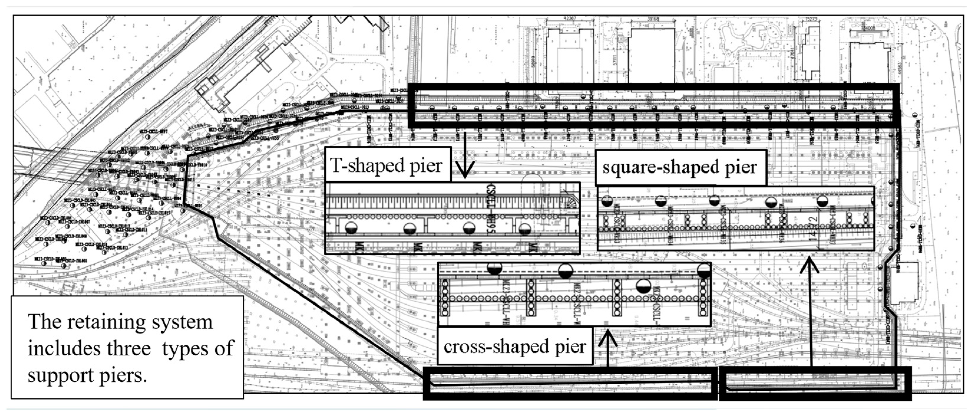
17]. The foundation pit project of Chisha Metro adopts a front wall and rear pile double-row support structure, and on the basis of the double-row retaining structure, support piers are added at regular intervals within the support structure, and different forms of support piers are applied in the actual engineering. Based on the construction monitoring data during the foundation pit excavation process, this paper uses numerical modeling to analyze the effects of different forms of support piers. It explores the sharing of stress between front and rear row structures, the variation of stress between support structures with depth, the overall stiffness of the spatial structure formed by the double-row support structure and pier, and the optimization of the pier layout form, in order to provide a better theoretical basis and guidance for engineering practice.
3. Numerical Simulation
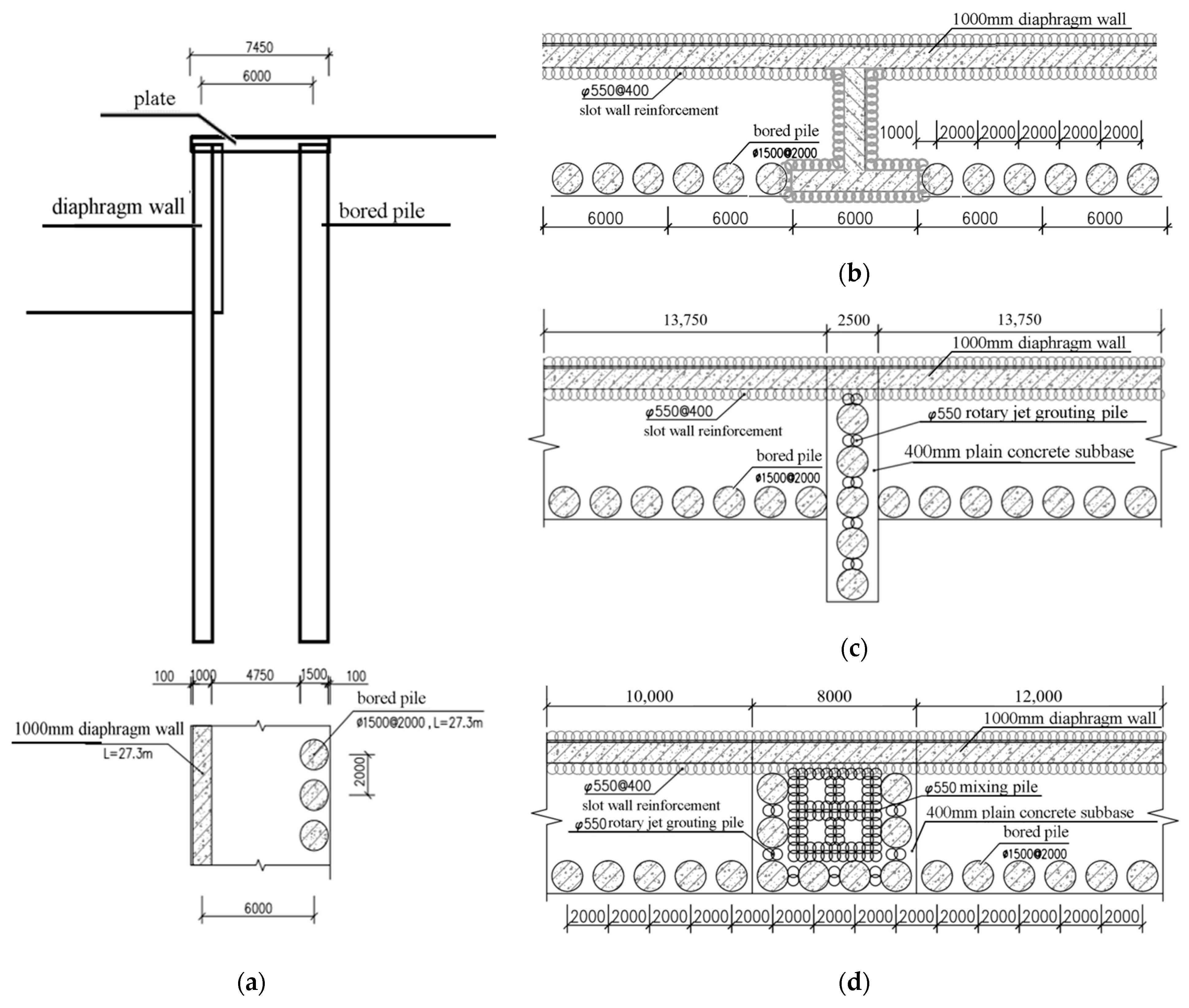
In this study, Plaxis3D v22.00.00.1733 software was used for numerical simulation. A typical excavation zone was selected for simulation, where the form of support pier is a T-shaped pier and the elevation at the bottom of the retaining structure is −21.7 m. The structure’s cross-section is modeled based on
Figure 2, which consist of diaphragm walls, bored piles, a top plate, as well as a pier every 30 m. The soil parameters are shown in
Table 1, and the materials for the support structure are shown in
Table 2. The construction steps of the model are shown in
Table 3.
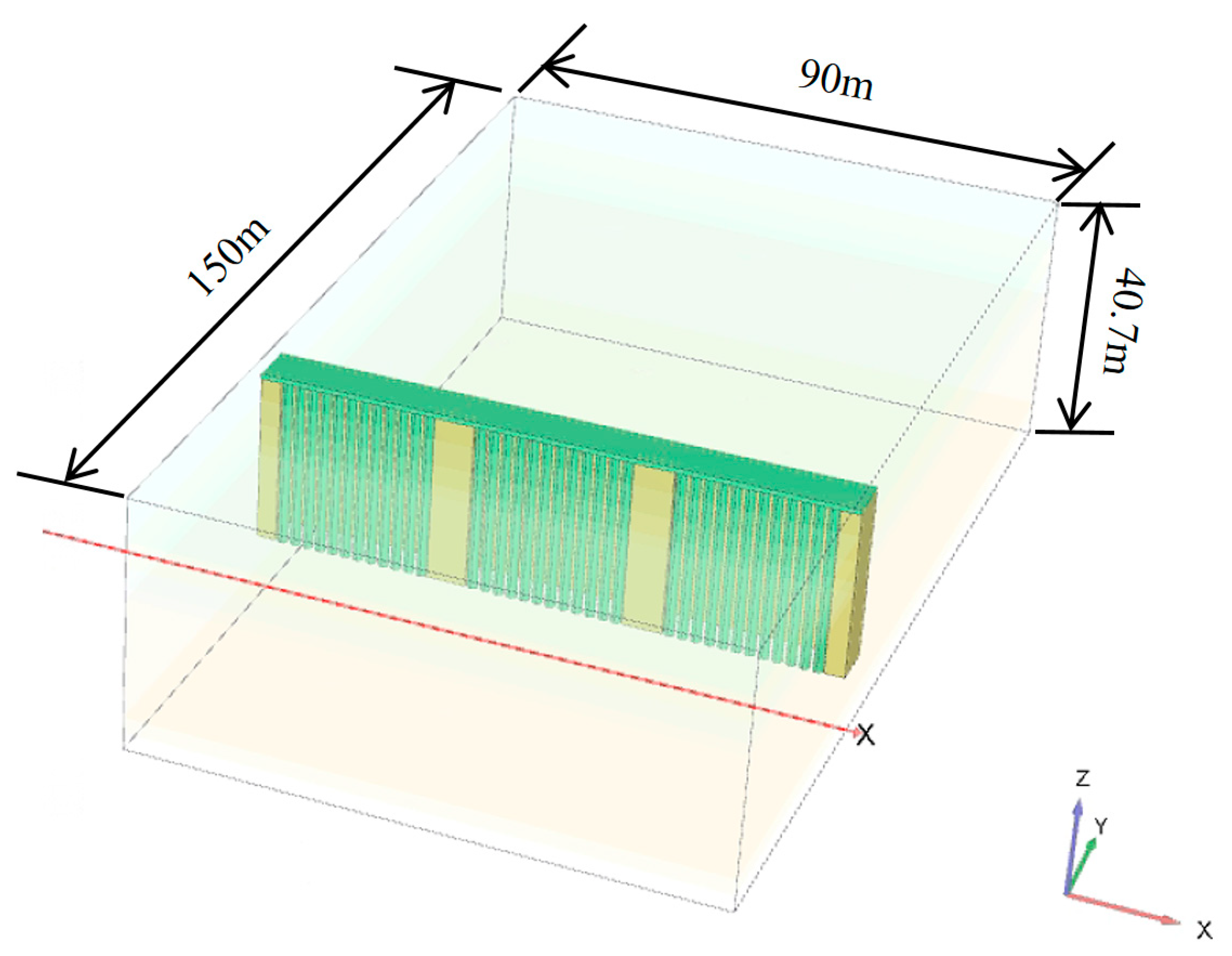
Three-dimensional solid elements were used. The small strain hardening model was used for soil, and the linear elastic model for the support structure. Rigid connections were employed among the structures, while interface elements were utilized for the interaction between a structure and soil. The shear behavior of the interface elements was modeled using the Mohr–Coulomb strength criterion within an elastoplastic framework, with the normal stress following a tensile cutoff criterion. As the structure traverses multiple soil layers, the properties of the interface differ in different soil layers. The strength and stiffness parameters of the interface elements were determined based on the material with lower stiffness or strength in the adjacent zone. In order to eliminate the influence of boundaries on numerical calculation results, the settlement range of the soil behind the wall caused by excavation of the foundation pit was approximately four times the depth of the foundation pit excavation, and the support structure was taken as three times the span length. The overall length of the model was 150 m, and the width was 90 m. The four sides of the model were restrained by setting zero normal displacement, and the bottom was restrained by setting zero horizontal displacement, which means that the mesh around the model could only move in the vertical direction, while the bottom mesh could not produce any displacement. The structural configuration of the model is shown in
Figure 5. The model was meshed using 10-node tetrahedral mesh elements, resulting in a total of 373,346 nodes and 230,571 elements. Based on geological survey data, combined with the Plaxis3D user manual and existing engineering experience, the soil layer model parameters are shown in
Table 4.
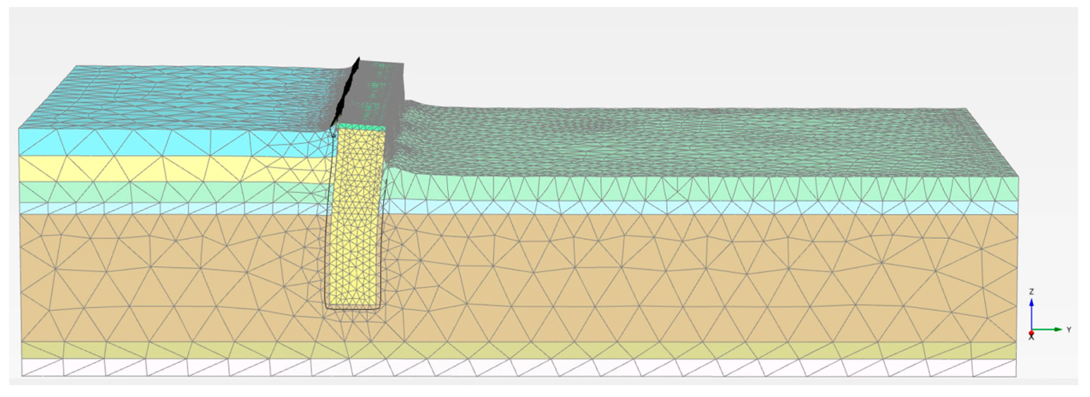
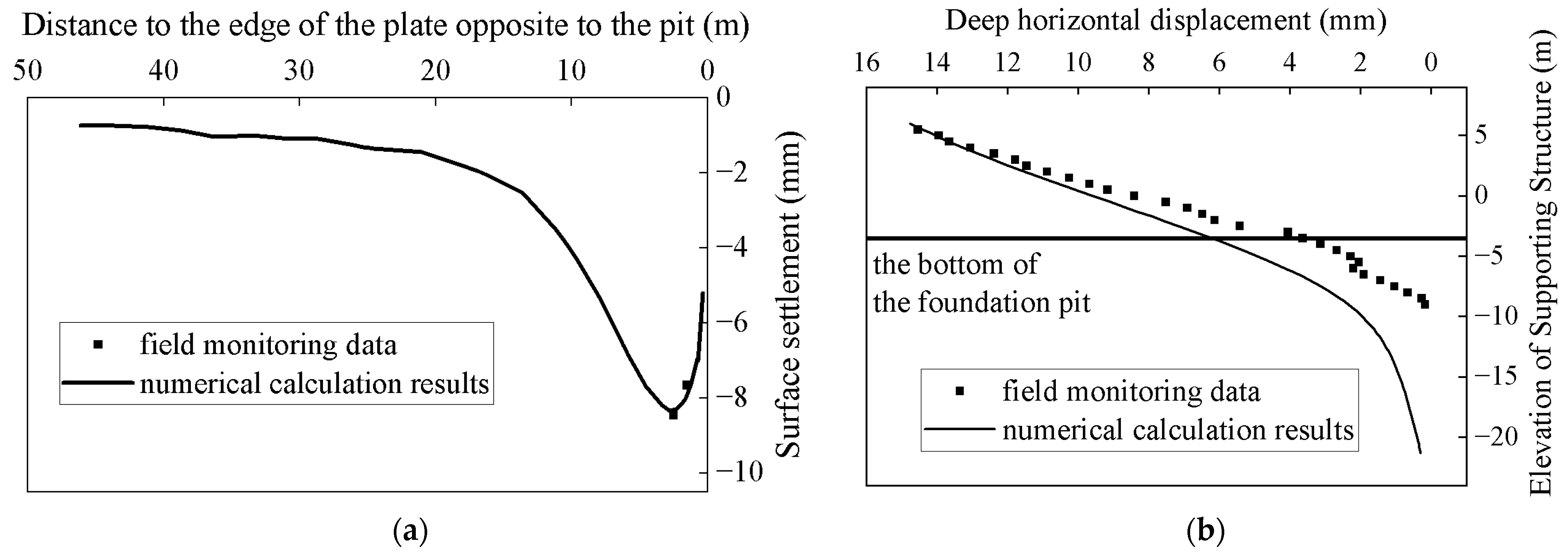
The deformation mesh after the completion of the excavation of the foundation pit is shown in
Figure 6. Tensile stress is considered positive, while compressive stress is considered negative. The displacement values in the analysis results represent the cumulative deformation after the support structure is completed and the excavation of the foundation pit begins. Positive displacement values indicate deformation towards the corresponding coordinate axis direction, while negative values indicate the opposite. From the deformation diagram, it can be seen that the bottom of the support structure is relatively fixed, the top bends towards the foundation pit, and the soil outside the foundation pit experiences surface settlement. As the distance from the foundation pit decreases, the surface settlement becomes larger and then decreases near the support structure. The numerical simulation results of excavating the area to the bottom of the foundation pit in this region are compared with the monitoring data, and the surface settlement and horizontal deformation of the piles are shown in
Figure 7.
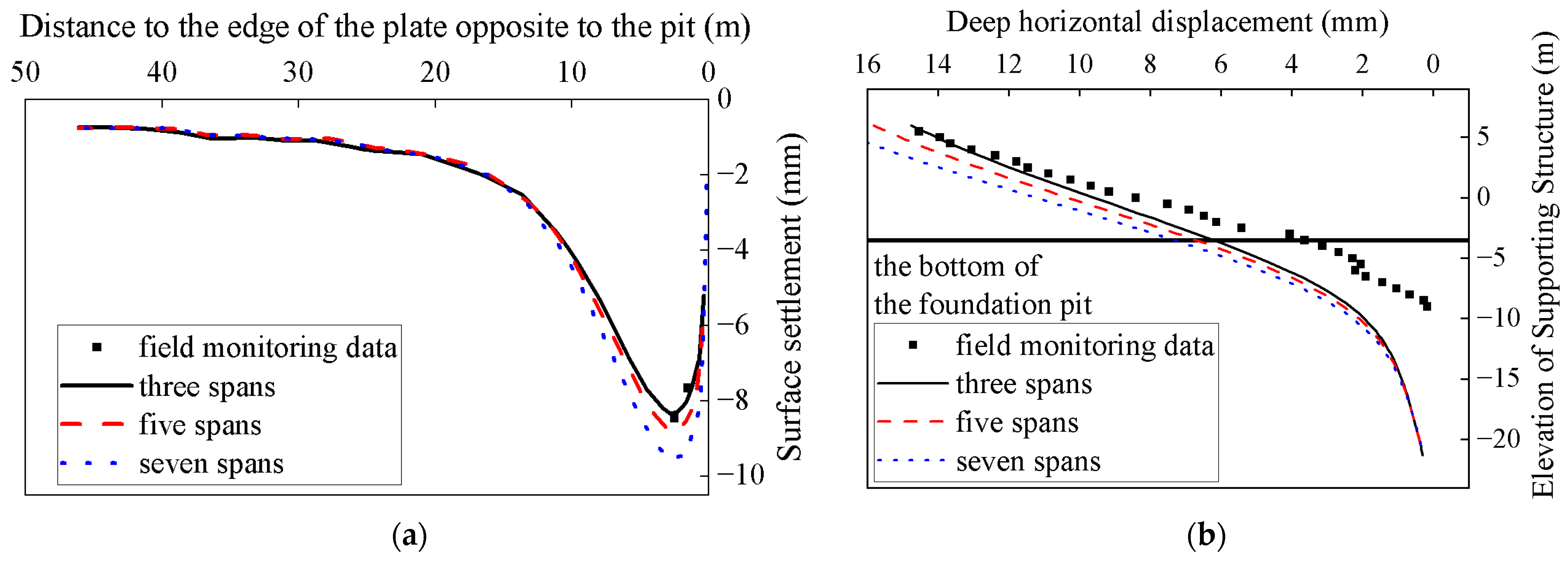
To assess the influence of boundary conditions, comparisons of surface settlements and horizontal deformations under different numbers of spans for the supporting structure are presented in
Figure 8.
As the horizontal distance to retaining structure decreases, the surface settlement gradually increases and then rapidly decreases, with the peak occurring within a horizontal distance of 10 m. The influence of excavation on the surrounding area gradually intensifies as the horizontal distance to the retaining structure decreases, leading to an increase in surface settlement. However, as the location approaches the vicinity of the retaining structure, the vertical displacement of the retaining structure is relatively small, resulting in a rapid decrease in soil settlement around the retaining structure. From
Figure 8, it can be observed that the horizontal displacement of the retaining structure decreases gradually with increasing depth. The horizontal displacement curve follows a similar pattern to that of a cantilever support structure. The base is embedded, and the maximum displacement occurs at the top of the support structure. Increasing the number of spans (three, five, or seven) leads to an increase in surface settlement and horizontal deformation, but the patterns remain consistent.
The numerical calculations obtained above are in good agreement with the field monitoring data regarding the deformation characteristics of the surrounding soil. This indicates that the selected model and computational methods are reasonable. In the next section, this reference model will be used, with some modifications made to analyze the stress distribution in the double-row supporting structure.
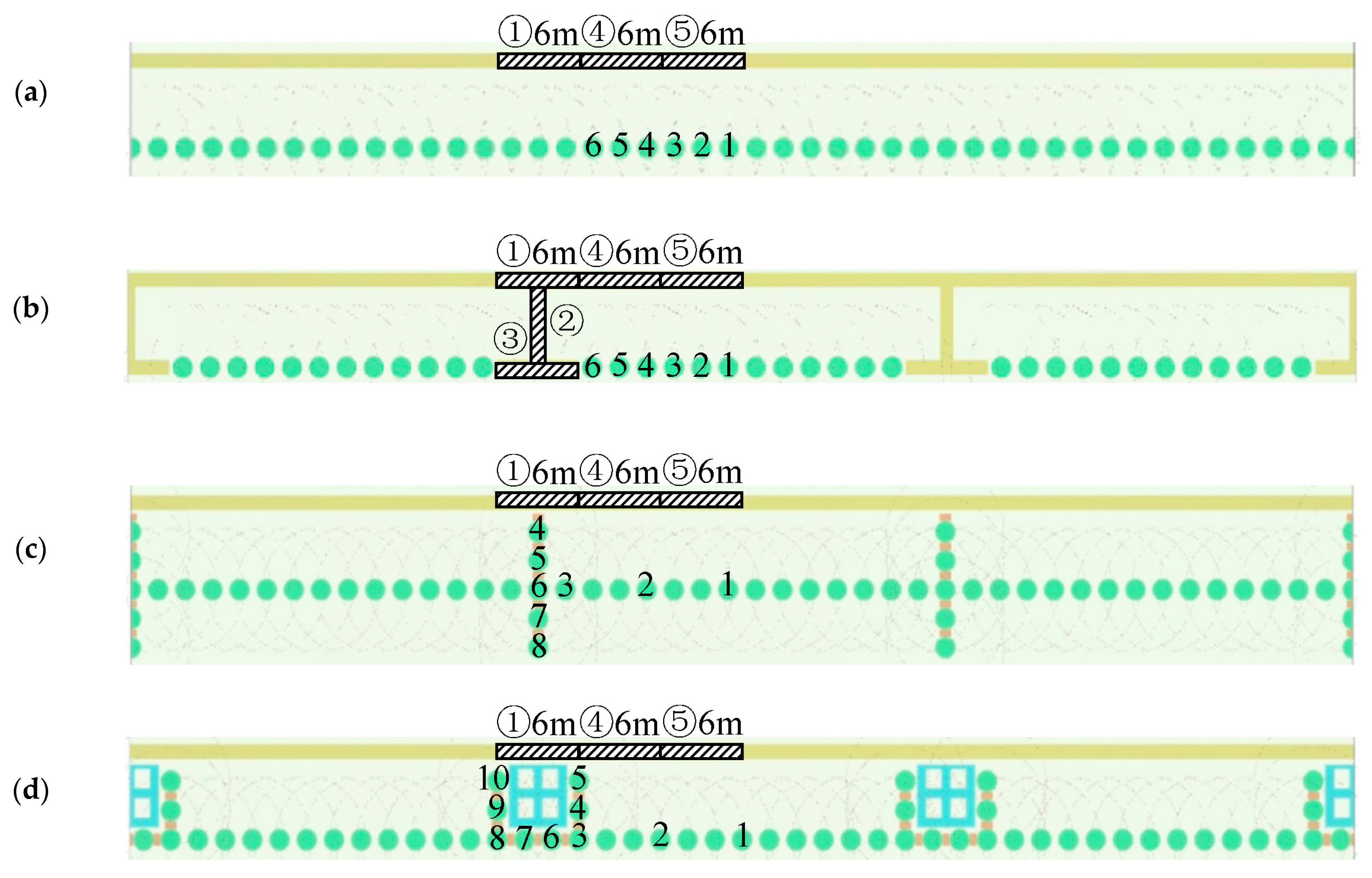
According to the reference model, only the pier type is changed. The original T-shaped pier is replaced with no pier, a cross-shaped pier, or a square-shaped pier, as shown in
Figure 9 (cover plates are concealed). At the same time, the rotary jet grouting pile for the cross-shaped pier and square-shaped pier is simulated with a rectangular shape that has the same total area as the previous two intersecting circles. The soil inside the square-shaped pier structure is reinforced with a grid-mixing pile, which is simulated using a checkerboard-like pattern in the model. The corresponding parameters of the support structure model are shown in
Table 5.
4. Results and Discussion
Based on the markings in
Figure 9, three 6 m wide sections were selected as typical cases to discuss the influence of internal forces and deformations on the double-row retaining structure. The retaining walls are labeled ① to ⑤, and the piles are labeled 1 to 6. The horizontal displacement and bending moment diagrams of the double-row retaining structure without pier, with T-shaped pier, with cross-shaped pier, and with square-shaped pier are shown in
Figure 10,
Figure 11,
Figure 12 and
Figure 13, respectively. The surface settlement diagram of soil reinforced by the double-row retaining structure with different piers is shown in
Figure 14.
In the double-row retaining structure without pier support, the cover plate connects the front and rear support structures, resulting in opposite bending moments, with increasing depth for the front and rear supports. The production of opposite bending moments leads to a more evenly distributed bending moment in double-row support structures, where the maximum absolute value of the bending moment is lower compared to single-row support structures, thus reducing the required amount of reinforcement material and resulting in cost savings. The forces and displacements experienced by each wall in the front row and each pile in the rear row are the same.
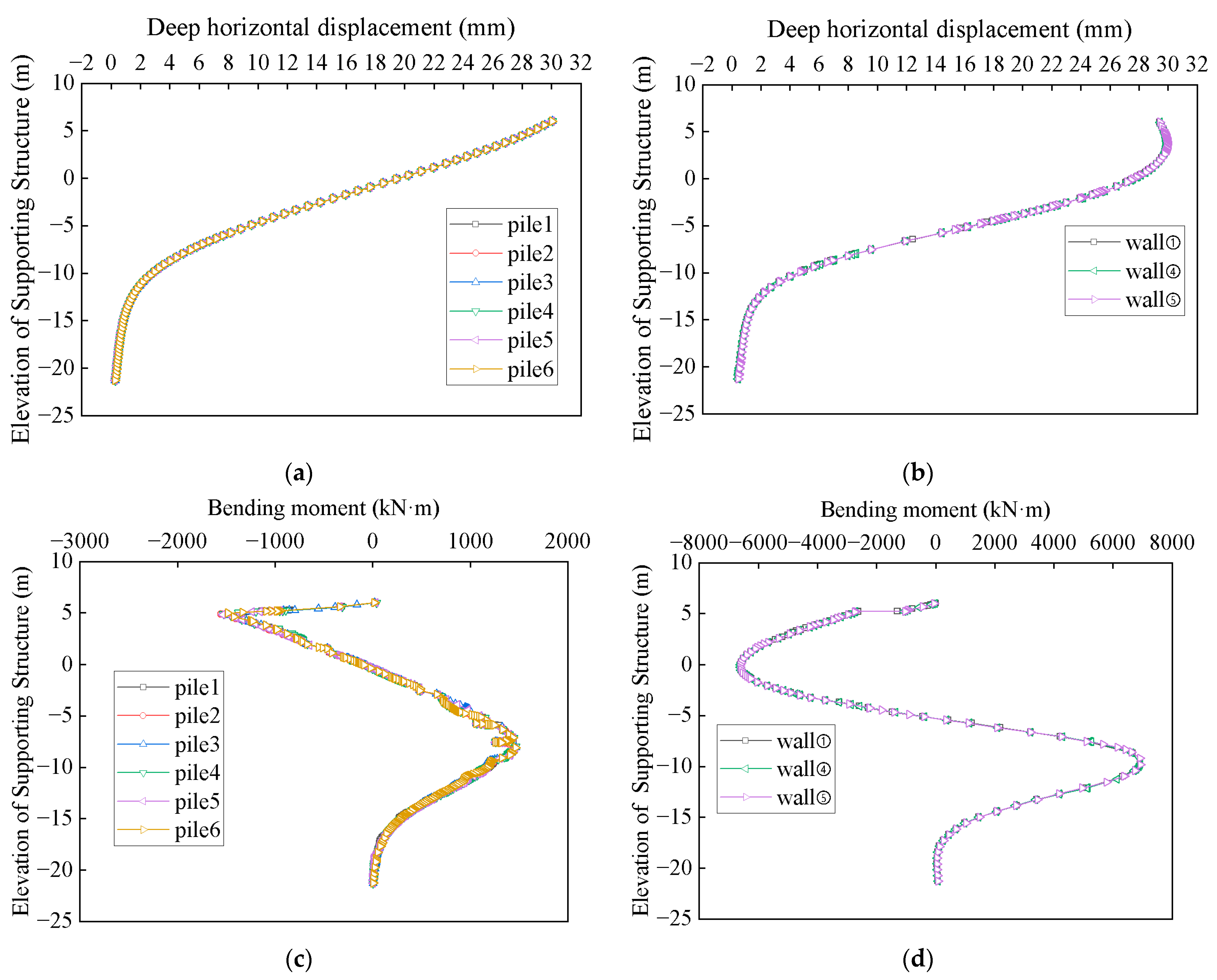
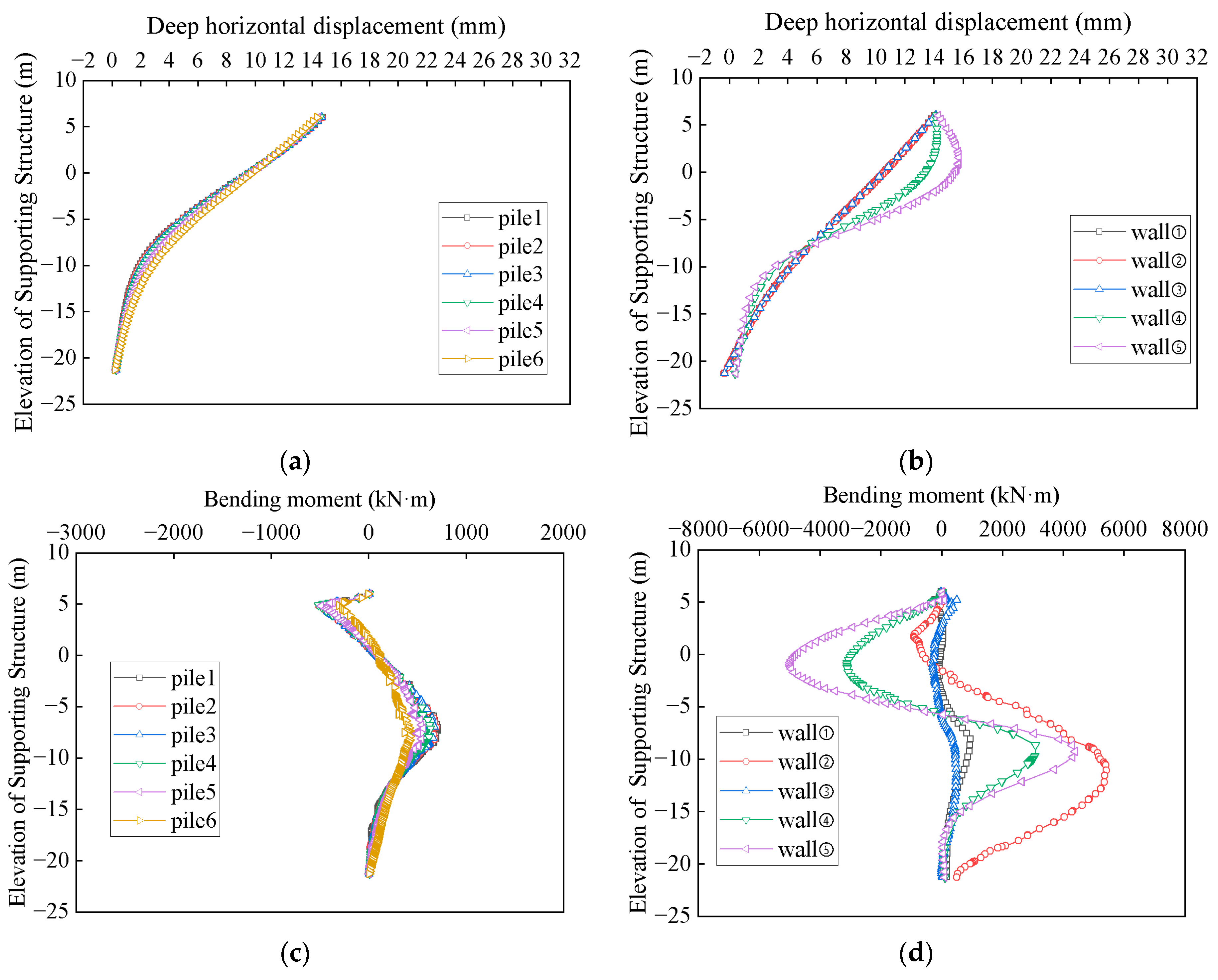
After introducing the T-shaped pier, the bending moment curves of the walls and piles at different locations change, indicating spatial characteristics and the transformation from a planar problem to a spatial problem. Compared to the double-row retaining structure without pier support, the maximum horizontal displacement of the piles decreases from around 26 mm to around 15 mm when the T-shaped pier is added. Additionally, the maximum negative bending moment value in the pile’s bending moment curve decreases from around −1600 kN m to around −500 kN·m, while the maximum positive bending moment value decreases from 1500 kN·m to around 700 kN·m. Both positive and negative bending moments are significantly reduced. Similarly, the maximum horizontal displacement of the walls, absolute values of maximum positive and negative bending moments in the bending moment curve of the walls also decrease significantly, with a reduction of approximately 46.77% in the maximum horizontal displacement of the walls.
For the retaining structure containing T-shaped piers, as shown in the horizontal displacement diagrams of the piles and walls, the horizontal displacements at different selected pile tops are all near 14.7 cm, while those at different selected wall tops are around 14 cm, and the horizontal displacements at the bottom of the piles and walls are close to zero. However, it can be observed from the figures that, compared to retaining walls ①, ②, and ③, the horizontal displacement curves of retaining walls ④ and ⑤ exhibit rebound at the top, with the maximum horizontal displacement occurring not at the top but near the top position. Due to the connection of the cover plate, the interconnection of the piles and walls at the top reduces the top displacement, and the difference in horizontal displacement at the top of both is determined by the tensile deformation caused by the stretching stiffness of the cover plate. Furthermore, due to the connection of retaining wall ② to retaining walls ① and ③, the three together form a pier, greatly enhancing their interconnected behavior. This interaction occurs not only at the top but at all depths, resulting in no rebound in horizontal displacement at the top, but rather an approximation to a straight line. This is also evident in the horizontal displacement at mid-to-lower depths: there is bending in the horizontal displacement of the piles and retaining walls ④ and ⑤, while the overall flexural stiffness is greatly increased due to the presence of retaining wall ②, and thus, no bending occurs in the middle section. The horizontal displacement curve at the pier location is approximately linear for the retaining wall, while the horizontal displacement curves for retaining walls ④ and ⑤ exhibit rebound instead of reaching the top directly. This indicates a significant increase in local stiffness at the pier location. At the same time, the horizontal displacement curves of all walls in the double-row retaining structure without a pier show rebound at the top due to the action of the cover plate.
For the retaining structure containing T-shaped piers, the overall trend of bending moment variation follows this: with an increase in depth, the piles and walls initially experience a negative bending moment, followed by a positive bending moment, and finally return to zero at the bottom. The bending moment directions are precisely opposite between the upper and lower sections. The bending moment borne by retaining walls ④ and ⑤ in absolute value is greater than the sum of bending moments borne by the corresponding three piles. Additionally, compared to the piles near the pier, the bending moment of the piles closer to the center of model gradually increases in absolute value. However, the increase in absolute value of the bending moment borne by retaining wall ⑤ compared to retaining wall ④ is much greater than the increase in the sum of absolute value of the corresponding three piles. This indicates that for the overall bending stiffness formed by the same piles and walls, the larger the bending moment they need to bear, the greater the bending moment borne by the components with higher stiffness. Regarding the three retaining walls forming the pier, the bending moment is mainly borne by retaining wall ②, which connects retaining walls ① and ③. The bending moment borne by retaining walls ① and ③ is much smaller than that borne by retaining wall ②. This indicates that connecting wall ② has a much higher ability to bear the bending moment in the direction perpendicular to the excavation edge than the retaining walls at locations ① and ③.
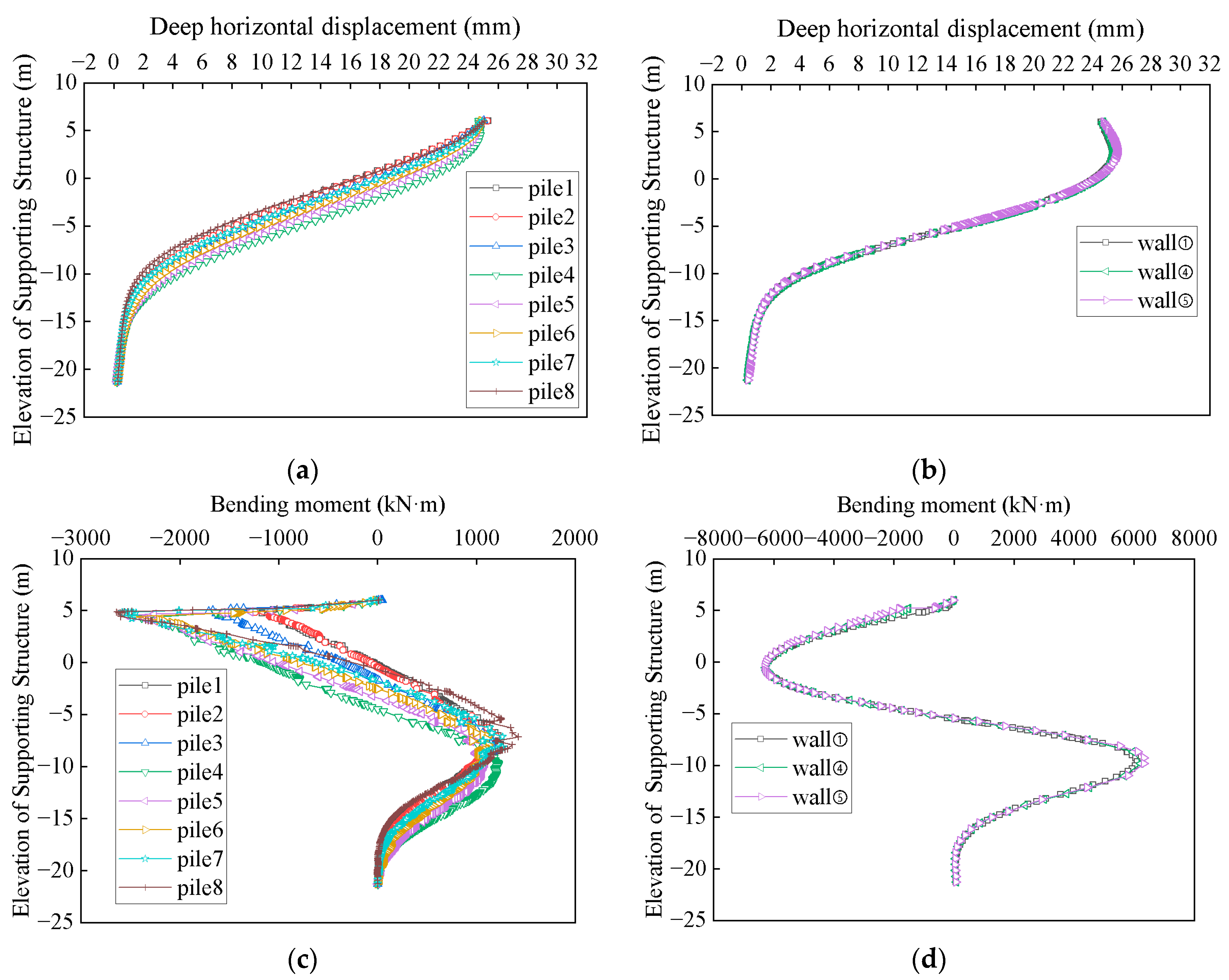
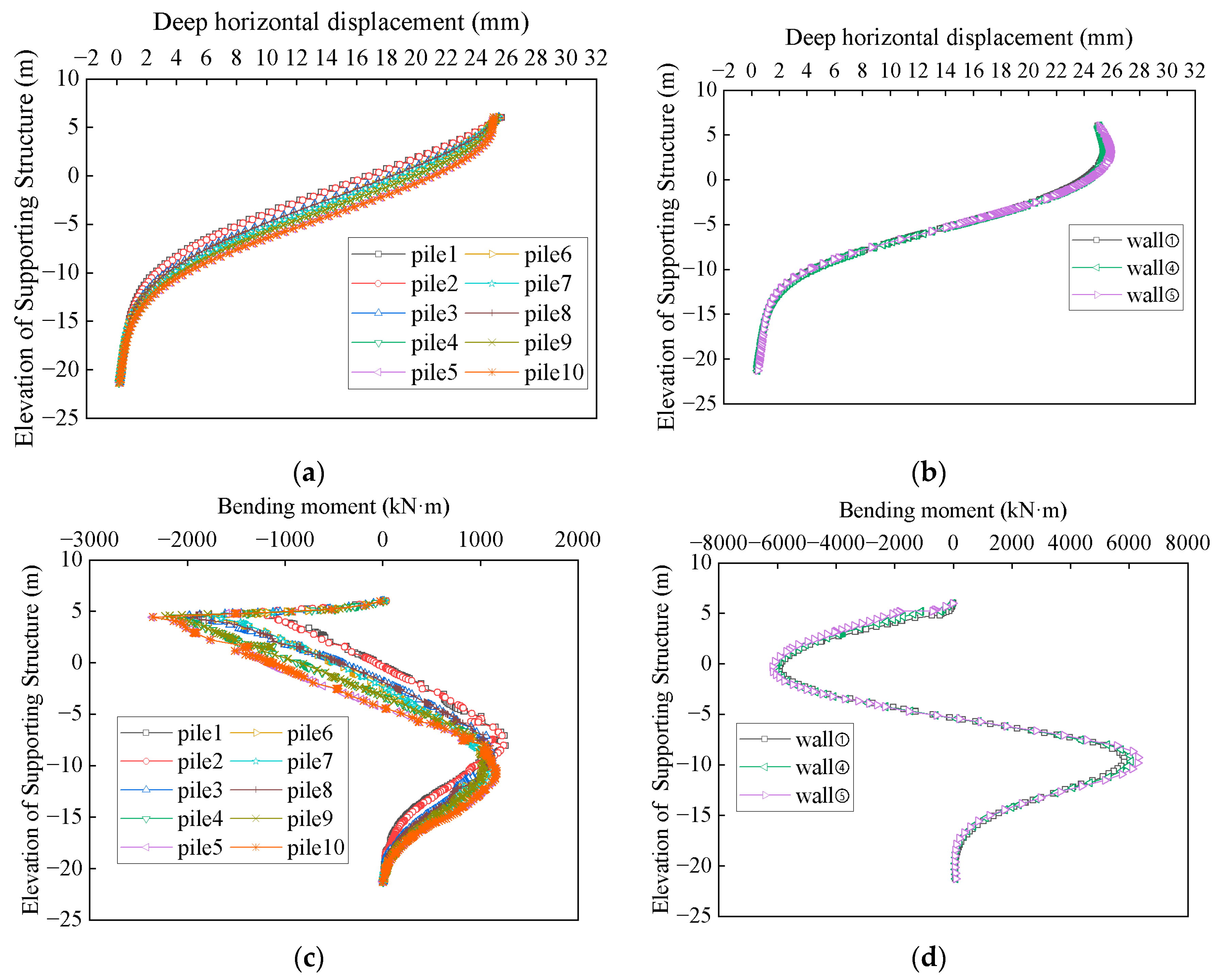
Similar to the retaining structure containing T-shaped piers, both the retaining structure containing cross-shaped piers and the retaining structure containing square-shaped piers exhibit consistent horizontal displacement between different piles at the top, with zero horizontal displacement at the bottom, and bending moment curves with a positive and negative bending moment. However, for the retaining structures containing cross-shaped piers and square-shaped piers, spatial variation is observed between different piles at different positions, but there is no spatial variation between different walls at different positions.
For pile 1 and pile 2 away from the support pier in the retaining structures containing cross-shaped piers and square-shaped piers, the deep horizontal displacement between the two piles is almost consistent. For piles 4 to 8 in the cross-shaped pier and piles 3–5 and piles 8–10 in the square-shaped pier, the top and bottom horizontal displacements between different piles of the same support pier type are basically consistent, and only the horizontal displacement in the middle part of the pile decreases gradually as the distance from the excavation pit increases, with a slight rise in the middle of the curve. For pile 3 in the cross-shaped pier and square-shaped pier, the horizontal displacement in the middle part is slightly increased compared to pile 2 near the support pier. Additionally, in the square-shaped pier, the horizontal displacement of piles 3 and 8, 4 and 9, 5 and 10, and 6 and 7 symmetrically positioned with the central axis of the support pier is almost consistent.
The characteristics shown in the pile bending moment correspond to the pile horizontal displacement. For pile 1 and pile 2 away from the support pier, the bending moment curve is basically consistent. For the cross-shaped pier, as the distance between the pile and the excavation pit gradually increases, the elevation corresponding to the maximum positive bending moment gradually moves up, and the value in the middle of the displacement curve slightly increases. For the square-shaped pier, as the distance between the pile and the excavation pit gradually increases, the absolute value of the maximum negative bending moment slightly decreases, resulting in a slight increase in the horizontal displacement in the middle of the pile. For pile 3, the maximum negative bending moment value slightly increases compared to pile 2, resulting in a slight increase in the middle horizontal displacement of pile 3. Additionally, in the square-shaped pier, the bending moment curves of piles 3 and 8, 4 and 9, 5 and 10, and 6 and 7 symmetrically positioned with the central axis of the support pier are almost consistent.
From
Figure 10,
Figure 11,
Figure 12 and
Figure 13, it can be seen that the horizontal displacement and bending moment curves between different walls of front row retaining walls are almost consistent when there is no support pier. At the same time, the horizontal displacement and bending moment curves between different walls of front row retaining walls in the retaining structures containing cross-shaped piers and square-shaped piers are also almost consistent. This indicates that wall ② is an important structure in the stress distribution of the support structure, which can connect the support structure, redistribute stress, and reduce stress on the front row retaining wall. In the retaining structure containing T-shaped piers, the top horizontal displacement of the retaining wall is the smallest, followed by the walls in the retaining structures containing cross-shaped piers and square-shaped piers.
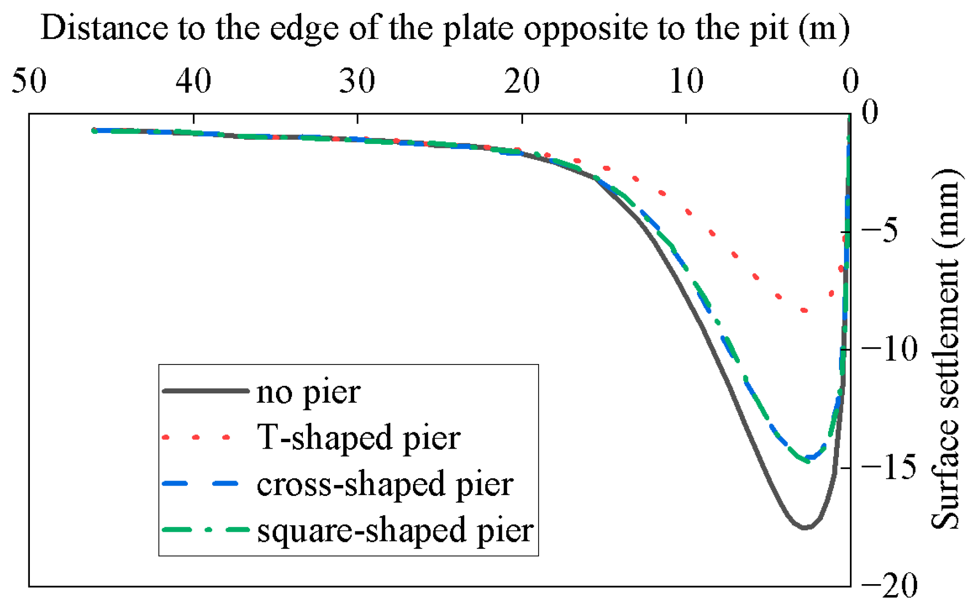
The surface settlement profile can correspond to the horizontal displacement and bending moment diagrams mentioned earlier. The retaining structure containing T-shaped piers exhibits the highest overall stiffness, while the retaining structures containing cross-shaped piers and square-shaped piers produce very similar effects. In the cross-shaped pier and square-shaped pier, the bored piles and soil-cement mixing piles replace the diaphragm walls, resulting in a significant decrease in overall stiffness. Under these geological conditions, the bored piles and soil-cement mixing piles in the cross-shaped pier and square-shaped pier fail to connect the front and back row support structures together. Instead, they mainly serve to reinforce the soil. However, in this geological condition where the soil quality is favorable, the reinforcement provided by the soil-cement mixture is not as effective as connecting the front and back row support structures.
To more intuitively display the differences between different supporting piers and the positions where the structure is most susceptible to damage,
Table 6 presents the values of maximum horizontal displacement, maximum positive bending moment, and maximum negative bending moment of piles and walls for a double-row retaining structure with various piers, accompanied by their corresponding elevations. Based on our previous findings, we have arranged the results from top to bottom in descending order of pier stiffness for ease of data observation as follows: “T-shaped pier, cross-shaped pier, square-shaped pier, no pier”.
In the cases of the double-row retaining structures with a cross-shaped pier and with a square-shaped pier, where the piers incorporate piles, the maximum negative bending moment occurs at the pier’s pile, leading to an increased maximum negative bending moment compared to the scenario without piers. However, the introduction of piers leads to a reduction in the maximum horizontal displacement and maximum positive bending moment of both piles and walls, along with a reduction in the maximum negative bending moment of walls.
As the maximum horizontal displacement of the double-row retaining structure with different piers diminishes, the corresponding elevations for the wall’s maximum horizontal displacement and extreme bending moment gradually decrease. Meanwhile, the elevations associated with those of the pile remain relatively consistent or increase. Furthermore, the elevations of the wall are generally lower than those of the pile. With increasing pier stiffness, the elevations corresponding to the wall move farther away from those of the pile, potentially reducing the likelihood of concentrated damage to both the wall and the pile.


