Review

Review on Vibration Monitoring and Its Application during Shield Tunnel Construction Period

1
Geotechnical and Structural Engineering Research Center, Shandong University, Jinan 250061, China
2
School of Qilu Transportation, Shandong University, Jinan 250002, China
3
Research Institute of New Material and Intelligent Equipment, Shandong University, Dezhou 251114, China
4
School of Civil Engineering, Shandong University, Jinan 250061, China
*
Author to whom correspondence should be addressed.
Buildings 2024, 14(4), 1066; https://doi.org/10.3390/buildings14041066
Submission received: 26 March 2024 / Revised: 8 April 2024 / Accepted: 10 April 2024 / Published: 11 April 2024
(This article belongs to the Special Issue Engineering Safety Monitoring and Management)

Abstract

:
With the rapid development of metro construction, shield machines inevitably have to traverse a variety of complex geological conditions, leading to the frequent occurrence of geological disasters, equipment failures, building vibration and other problems. Vibration, as an important feature of the shield tunneling process, has received more and more attention in recent years. This paper summarizes the relevant research progress of vibration monitoring during shield construction from 2015 to 2023. It analyzes the shield vibration generation mechanism, monitoring methods and application areas. Firstly, the shield vibration type is divided into mechanical vibration triggered by internal excitation and forced vibration triggered by external excitation, and the principles of vibration generated by shield main bearing, gearbox and disc cutter are discussed. Then, the commonly used vibration monitoring methods are outlined according to the installation location of the sensors (inside and outside of the shield). Finally, the applications of vibration signals in the diagnosis of shield faults, the identification of geologic conditions, and the evaluation of the current status of the interference with the buildings are summarized. This paper discusses the development trend of vibration monitoring during shield tunneling based on the current research situation and the current technology level, which provides valuable insights to enhance the safety and intelligence of shield construction.

1. Introduction

Shield machines have been widely used in metro construction due to their advantages of high mechanization, high construction efficiency, a high safety factor, and minimal environmental impact [1,2,3]. However, with the rapid and large-scale construction of metro networks, shield machines inevitably have to traverse complex geological conditions, such as water-rich karst strata, composite strata, fault fracture zones, and extremely hard-rock strata [4,5,6,7]. During shield tunneling construction, the cutterhead usually generates violent vibration. On the one hand, severe vibration may cause damage to the shield structure and increase the risk of shield construction [8]. On the other hand, the vibration of the cutterhead reflects the working performance of the shield machine [9]. Therefore, to avoid engineering accidents such as geological disasters and equipment damage, the study of shield vibration characteristics has become a hotspot for scholars in recent years, including vibration generation monitoring and application. Figure 1 shows the schematic diagram of shield vibration propagation.
As the core component in direct contact with the surrounding rock, the disc cutter bears the impact load from the rock–soil body during excavation, and the load is transferred to the cutterhead to cause the vibration [10]. In addition, in the process of equipment operation, the vibration generated by the motor, gears and other equipment is also inevitable [11]. But these two types of vibrations often differ significantly in intensity, making them distinguishable. The former has been extensively studied in the geotechnical engineering field, while the latter has been more studied in the mechanical engineering field. Due to the existence of a closed pressure chamber in front of the shield machine, it is impossible to directly observe the stratigraphy of the excavation surface and the working status of the cutterhead. A large number of practices have proved that the vibration signal of the shield machine is sensitive to the response of the stratum characteristics [12], but the direct monitoring of the vibration of the disc cutter faces great challenges. Therefore, how to effectively monitor the vibration signals in shield construction and extract effective features has become the focus. In the field of geological investigation, traditional geophysical equipment is not suitable for work due to the large space occupied by shield tunneling machine auxiliary equipment in the tunnel and the absence of exposed surrounding rock. Therefore, the use of vibration signals generated by the rock breaking of the disc cutter, to realize the prediction of geological development conditions in front of the excavation surface, is also favored by scholars. Despite this, the vibration intensity generated during shield construction is relatively low, and their impact on surrounding buildings is minimal. However, as the depth of the shield tunnel becomes shallower, it will inevitably cause disturbance to the nearby buildings and people [13]. Therefore, monitoring vibrations near buildings and optimizing shield tunneling construction accordingly is also of great significance.
This paper reviews the relevant research on vibration characteristics during shield tunneling over the past decade, discussing the generation, monitoring, and application of vibrations. Firstly, the mechanism of vibration generation is discussed from both internal and external aspects. Then, the monitoring techniques and methods of vibration signals are introduced. Finally, the application scenarios of vibration signals are summarized, including the identification of mechanical failures, the prediction of geological conditions, and the assessment of their impact on surrounding buildings. The development trend of the application of shield vibration signals is also discussed.

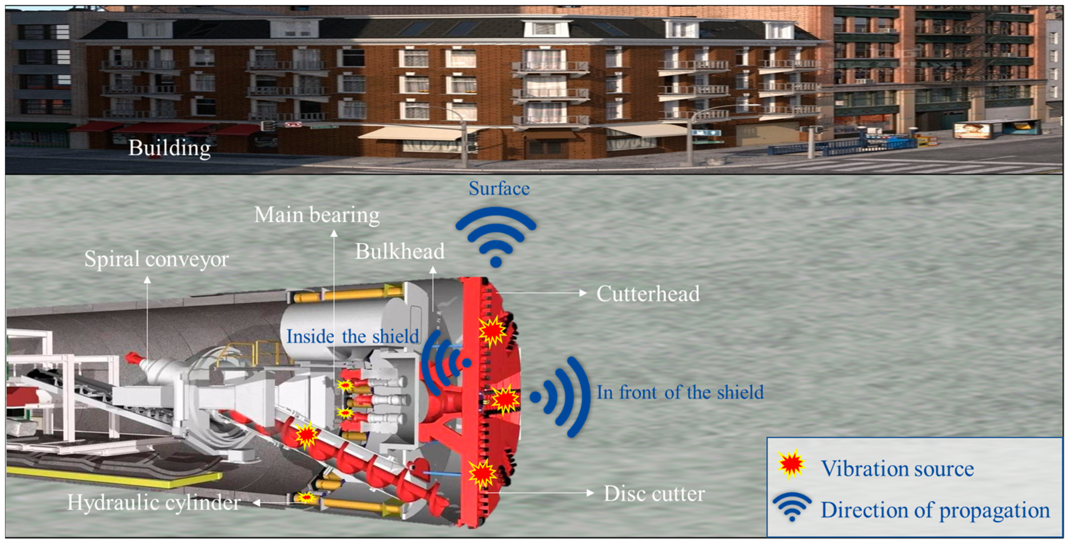
2. Source of Shield Vibration Signal

During shield tunneling, the vibration in the cutting system mainly originates from two sources. One is the internal excitation generated during equipment operation [14], which also occurs when the shield machine is idling. The other is the external excitation generated by the interaction between the cutter and the rock-soil, resulting in impact loads [15], which is only generated when the shield machine is digging. Typically, the external excitation is a large shock load that produces more intense vibrations than those produced by internal excitation.

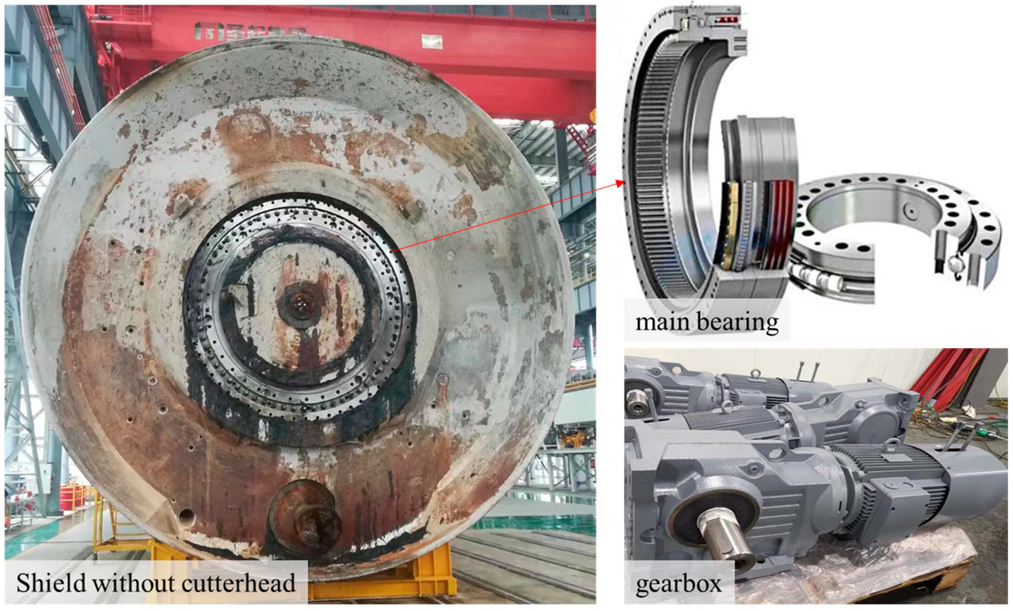
2.1. The Internal Excitation

A shield machine can be divided into two major parts: the main machine and the auxiliary equipment. The main machine is responsible for excavation and soil transportation, while the auxiliary equipment is responsible for tasks such as segment assembly. The main machine mainly includes two kinds of motion attitude control, namely, cutterhead rotation and propulsion, powered by the main drive system and hydraulic cylinder, respectively [16]. The auxiliary facilities primarily operate within the pre-assembled segments, and their vibration mainly affects the structures of the segments rather than being considered as internal excitation for cutterhead vibration.
The main bearing of the shield machine is responsible for transmitting the thrust and radial forces in the direction of advancement of the cutterhead, and for bearing the torque generated by the rotation of the cutterhead and the overturning torque generated by the weight of the cutterhead. The gearbox, as the core component of the main drive of the shield machine, generally adopts a three-stage planetary gear transmission system, characterized by a compact structure and strong load-bearing capacity. The gearbox usually works under the conditions of a low speed and heavy load, huge torsional impact and harsh environment, which inevitably generates vibration during operation [17]. Figure 2 shows the main bearing and gearbox of the shield machine. To avoid abnormal vibration leading to equipment damage, scholars have developed a variety of computational models to explore the generation mechanism of vibration signals.
Jones [18] established the equilibrium equations of forces and moments between rolling elements, and firstly proposed a quasi-static model of cylindrical roller bearings on the basis of raceway control theory. Li et al. [19] proposed an improved quasi-static model on the basis of this model, used it to calculate the friction torque of high-speed spindle bearings. Yu et al. [20] further considered factors such as the thickness of the oil film in the raceway of the bearing and the deformation of the inner ring by the centrifugal force of rollers, and then analyzed the dynamic characteristics of the bearing. Niu et al. [21] created an improved ball bearing vibration analysis model, and analyzed the dynamic response of ball bearings. Wang et al. [22] explored the effect of the change in meshing stiffness on the vibration response of the system by establishing a six-degree-of-freedom dynamics model. Nie et al. [23] proposed the equivalent transfer path function for the first time, and constructed a vibration signal model of a multistage planetary gear system by considering the time-varying effect of the transfer path from the source of the meshing vibration to the sensor with a fixed position. Mishra et al. [24] constructed a dynamic model of localized bearing failure by using virtual prototype technology. Furch et al. [25] established a pure rigid body simulation model of a planetary gearbox based on ADAMS to study the failure characteristics of the intertooth contact force in the time and frequency domains in the case of distributed faults and localized faults. Guo et al. [26] optimized the expansion path of the sun wheel gear in the model, and established a two-stage planetary gear rigid-flexible coupling model to analyze the vibration response of the system under different crack depths of the sun wheel. Zhang et al. [27] established a dynamic model of the tunnel boring machine considering periodic meshing stiffness and speed-torque characteristics. Sun et al. [28] established a dynamic model of multi-stage planetary gear systems for tunnel boring machines based on the centralized mass method. Yang et al. [29,30,31] proposed an elasticity model considering the rock boundary, actuator stiffness, joints and key components. Li et al. [32] established a theoretical model of health dynamics and a failure dynamics model of a three-stage planetary gearbox, and analyzed the effect of tooth wear depth on the meshing force of each stage.

2.2. The External Excitation

In the shield tunneling process, the disc cutter, as the core component that cuts the surrounding rock directly, is subjected to the reaction force of the surrounding rock, and the rock-breaking load is transferred to the cutterhead through the cutter shaft, resulting in the mechanical imbalance of the cutterhead structure, which generates vibration in all directions. Especially in the hard rock and composite strata, the disc cutter is subject to the impact load from the rock, which is more obvious. The synthetic load of the lateral and vertical forces of the disc cutter generates radial vibration of the cutterhead, and the torque caused by the rolling force of the disc cutter generates torsional vibration of the cutterhead.
Since the 1960s, many scholars have begun research on the theory of disc cutter rock breaking, proposing many classical computational models, such as the shear fracturing model [33,34], the tension fracturing model [35] and the CSM model [36]. These models can obtain the force situation when the disc cutter interacts with the rock. All these models simplify the disc cutter rock breaking process to a static process, and it is difficult for this to truly reflect the dynamic changes of the disc cutter force. Based on extensive field practice and laboratory testing [36,37,38,39], it has been observed that the rock breaking process with disc cutters exhibits significant dynamics and abrupt changes. The disc cutter load oscillates violently during the cutting process, resulting in strong vibration of the cutter and the surrounding ground.
Huo et al. [40,41,42] developed a multi-degree-of-freedom coupled dynamic model consisting of cutter ring, cutter body, and cutter shaft to better understand the load transmission and vibration characteristics of disc cutters. Furthermore, they constructed a test bench for the main system of a hard rock tunnel boring machine. By considering time-varying external random excitations of the cutters, time-varying meshing stiffness of the gears, meshing errors, and main bearing stiffness, they established a multi-degree-of-freedom coupled dynamic model to study the load and vibration characteristics of the cutterhead [43]. Liao et al. [44] established a multi-system coupled closed dynamics model by considering the closed structure of the shield machine and the interaction with the rock, and the equations of motion of each rigid body in the tunnel boring machine system in generalized coordinates were derived. Sun et al. [45] proposed a new dynamic cutting force model (DCFM) with rock and operating parameters. Xu et al. [46] analyzed the effect of cutting depth and cutter penetration force on cutter vibration, and found that the most severe vibration occurs in the normal direction of the disc cutter, and the greater the penetration, the more intense the vibration.
To more realistically reflect the rock breaking process of the disc cutter, scholars have carried out a series of tests to study the dynamic response characteristics of the disc cutter under different stratigraphic conditions, including the linear cutting test and rotary cutting test (Figure 3) [47,48]. In the early stage of the research, the linear cutting test was widely used as a reliable and accurate method to predict the disc cutter force [47,49,50]. The linear cutting test uses an actual disc cutter to cut the rock specimen and measure the cutting force. The disc cutter cuts the rock by setting parameters such as disc cutter pitch, penetration, and thrust. The test results are used to establish the relationship between the disc cutter force and other factors, which in turn is used to predict the performance of the disc cutter under different stratigraphic conditions [51,52,53,54].
Although the basic disc cutter force can be obtained by linear cutting test, the rock-breaking method used in the test is different from the rotary cutting of the disc cutter in the actual project. It is not possible to consider the lateral force on the disc cutter with a small installation radius during operation. Therefore, the rotary cutting experimental equipment was developed to more realistically reflect the force state of the disc cutter [55].
Gong et al. [56] analyzed the effects of high ground stress, cutterhead rotation and the simultaneous cutting of rock by multiple cutters on the disc cutter force. Peng et al. [37] carried out rotary cutting tests with fixed penetration mode and fixed normal force mode. The effects of the two control modes on the normal force, rolling force and cutting coefficient of the disc cutter were analyzed. Pan et al. [57] conducted rotary cutting tests on cement mortar specimens using disc cutters with different installation radii (360–850 mm). The effects of disc cutter mounting radius and penetration on the force were investigated, and it was concluded that the disc cutter cutting force was very unevenly distributed on the cutterhead. Wen et al. [48] investigated the cutting performance of the disc cutter and analyzed the force under composite stratum conditions. Deng et al. [58] developed a new type of rotary cutting platform, which can realize rotary cutting up to a diameter of 3.3 m.
With the rapid development of computers, numerical analysis methods are more and more favored by scholars. Numerical simulation can both highly restore the dynamic process of disc cutter breaking rock, and make up for the shortcomings of high cost and poor repeatability of indoor tests. Commonly used numerical analysis methods to simulate the rock breaking of a disc cutter include FEM [59], the GPD method [60], FEM-SPH [61], FEM-DEM [62], 3DEC [63], FLAC3D [5], RBD-DEM [64], PFC3D [65,66], MatDEM [67], and Peridynamics [68].
In summary, there are many reasons for vibration in shield construction, and the vibration generated when the disc cutter cuts the surrounding rock is the most intense, which is a hot spot in the field of geotechnical engineering research. The vibration is directly related to the force, especially in hard rock or composite stratum conditions, the disc cutter is subjected to impact loads, which causes violent vibration. Scholars have studied the force by means of theoretical derivation, indoor test and numerical simulation. The disc cutter force has a great relationship with the cutter structure, cutter installation radius and digging parameters. Therefore, according to the research results of disc cutter force and vibration characteristics, it is necessary to optimize and improve the shield disc cutter and cutterhead. For example, it is necessary to improve the material properties of the disc cutter, increase the auxiliary rock-breaking functions such as water jets and lasers, and adjust the digging parameters.

3. Vibration Monitoring Methods and Techniques

Common vibration monitoring methods include internal and external monitoring of the shield machine. Internal monitoring can be divided into direct monitoring at the location of the vibration source and indirect monitoring on the vibration signal propagation path; external monitoring is mainly for vibration monitoring outside the shield tunnel.

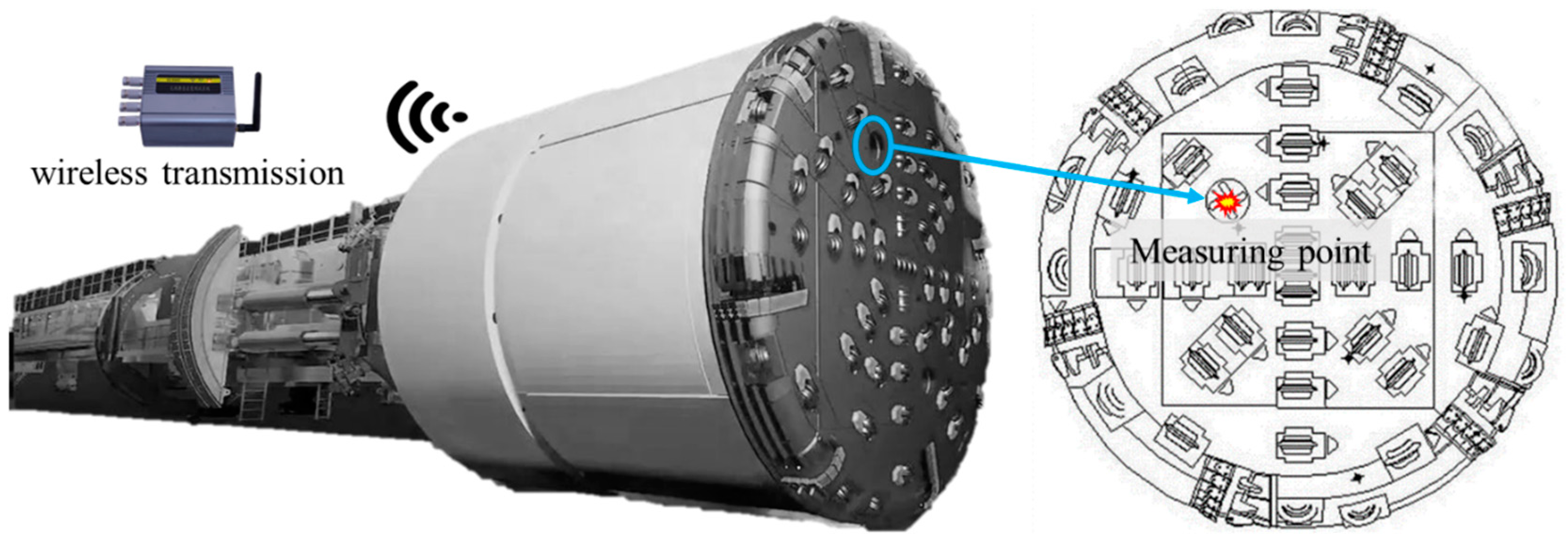
3.1. Direct Monitoring within the Shield

As a direct rock-breaking tool, the interaction between the disc cutter and the surrounding rock is the main source of vibration. Therefore, installing sensors on or near the disc cutter to monitor the vibration signal is the most intuitive and effective way to obtain the vibration signal.
Yang et al. [69] carried out a model test of shield vibration characteristics under composite stratum conditions, and found that different non-homogeneous stratum conditions mainly affect the cutterhead acceleration amplitude and frequency distribution, and the greater the strength difference between hard rock and soil at the excavation surface, the greater the vibration acceleration and the more concentrated the vibration frequency. The radial and circumferential vibration acceleration of the cutterhead at different positions are not very different, but the axial acceleration is very different, which provides a basis for the development of the field monitoring program.
Ling et al. [70] established a virtual prototype of the main machine system of a tunnel boring machine by comprehensively considering the spatial multi-point random excitation of the main bearing, the split cutterhead structure and the multi-directional support stiffness. A vibration monitoring system of a tunnel boring machine was constructed and applied in a water diversion project in China with the vibration sensor installed in the disc cutter access port, as shown in Figure 4. It is proposed that the horizontal and vertical acceleration of the cutterhead when rotating is affected by gravity, and the axial acceleration is not affected.
Huang et al. [71] developed a real-time monitoring system for tunnel boring machine interaction with surrounding rock. The monitoring system consisted of sensors, a data acquisition subsystem, a remote data transmission–storage subsystem and a data analysis subsystem, a set of BeeTech A302EX acceleration sensors was used to monitor the cutterhead vibration, and the monitored data were transmitted wirelessly to the system software, as shown in Figure 5. A time domain and spectral frequency domain analysis method of the acceleration rate of cutter vibration was proposed.
Wu et al. [72] developed a cutterhead vibration monitoring system, which consists of a data acquisition module, a communication control module, and a data processing and display module. The acceleration sensor, gyroscope and clock chip are integrated into the sensor board, which are used to obtain the three-axis vibration data, the rotating state of the cutterhead and the acquisition time. The sensors were mounted on the spokes behind the cutterhead of the shield tunnel boring machine (Figure 6). The results showed that the vibration was exacerbated by the increase in cutter force and penetration rate. In addition, the vibration amplitude was reduced when tunneling in a fault zone. Liu et al. [73] constructed a random forest model of multidimensional vibration features and tunnelling parameters using the data obtained from the above monitoring system, and filtered the vibration features that responded sensitively to the changes of tunnelling parameters by its feature importance evaluation function. It is believed that the peak factor and frequency standard deviation are the features that can best respond to changes in thrust and rotational speed, and can be used as key features to study the relationship between vibration signals and changes in tunneling parameters.

3.2. Indirect Monitoring within the Shield

However, the operating environment of the disc cutter and cutterhead is extremely harsh, and the closed pressure chamber of the earth pressure/slurry balance shield poses a huge challenge for signal transmission. To directly obtain the cutterhead vibration signal, it is generally necessary to modify the shield machine. Therefore, many scholars have begun to study how to monitor the vibration signal without modifying the existing equipment. The vibration signal generated when the disc cutter breaks the rock can be transmitted to the bulkhead through a series of connecting parts such as the disc cutter–cutterhead–main shaft [74,75]. Therefore, the vibration information of the cutterhead can be obtained by arranging vibration sensors at the bulkhead of the shield, and the effective features can be extracted as the basis for further research.
Xin et al. [76] developed a vibration sensor VM-BOX for shield machines, equipped with accelerometers of 16 g and 200 g ranges. It achieved the remote real-time online monitoring of equipment vibration data. Liu et al. [12,77] installed four vibration sensors on the bulkhead of the shield machine; the fixation method was magnetic suction. The relative positions of the sensors are shown in Figure 7b. This scheme is easy to realize, requires no modification to the shield machine, and does not affect the normal tunneling of the shield machine.
Fang et al. [78] installed a real-time dynamic response monitoring and analysis system in a slurry tunnel boring machine of a water transfer tunnel in Beijing. The system consisted of three IVS101 magnetoelectric vibration acceleration sensors, a signal acquisition instrument, and a dynamic signal analysis system. Considering that the underground water pressure of the project was as high as 0.32 MPa, which exceeded the pressure limit of the vibration sensors, they could not be installed on the cutterhead panel. The three sensors were set near the cutterhead bearings, on the inner wall of the manlock and on the ring beam in front of the jack, as shown in Figure 7c. The vibration waveforms were recorded every 15 min, and a total of 2000 acceleration responses were recorded during the 0.5 s monitoring period.
Shen et al. [79] also used sensors arranged at the back of the bulkhead inside the shield machine to monitor the vibration signals. The monitoring system included one triaxial accelerometer and three unilateral accelerometers, the type specification of the sensor was MPS-ACC03X/01X-IEPE, and the fixing method was magnetic suction, as shown in Figure 7d. The system was applied at the project site of Guangzhou–Foshan Intercity Railway.

3.3. Monitoring Outside the Shield

Shield structures are increasingly used in the construction of underground spaces in urban areas and are the main method for tunneling through rivers. The construction vibration problem caused by the shield machine seriously affects the human comfort of the ground building. To study the effect of shield vibration on the nearby buildings and strata, it is a good choice to deploy sensors to collect vibration signals inside the strata or on the surface.
Lu et al. [80] developed a shield machine construction site monitoring program for the range of shield vibration effects on human comfort, relying on the Qingdao Metro Line 4 project. Twenty-seven low-frequency vibration sensors (JX941) were deployed on the surface and underground to monitor the internal vibration of the ground during shield construction, as shown in Figure 8. Wu et al. [81] installed vibration sensors on the tube sheet to obtain the vibration signals during the shield construction. And the three-dimensional fully coupled dynamic model (3DFDM) of tunnel–hard rock–construction was established. Further vibration data were measured at the surface above the shield by a DH5923 dynamic signal test and Laser Doppler Vibrometer-PDV100 at three points at the bottom of the sidewall of the building.
Wang et al. [82] deployed multiple acceleration sensors on the surface and inside the strata to conduct shield vibration field monitoring tests, and the monitoring scheme was similar to the monitoring scheme in Ref. [48]. The authors combined theoretical methods such as normalization, polynomial fitting prediction and grey correlation analysis to investigate the vibration characteristics of shield machine construction, the range of impacts on the environment, and factors affecting vibration. Rallu et al. [13] conducted vibration measurements on four shield tunnel projects in France. These measurements installed vibration sensors on the ground surface and inside the shield machine. The monitoring system in the Lyon railroad project (Figure 9) consisted of 8 3D geophones (2 inside the shield: C3 and C4; 6 on the surface: C1, C2, T70, T71, T75, and T76) and 18 1D geophones (TR01 to TR18).
In addition, with the development of computer technology and intelligent technology, some scholars have proposed a new method to obtain shield vibration information. Yang et al. [83] established a multiple regression prediction model of vibration signals based on the vibration information of the main beam of the tunnel boring machine under different surrounding rock conditions. This method can be used to predict the vibration in real time through the characteristic parameters without using traditional vibration monitoring equipment. This method provides a new idea for determining the state of tunnel boring machine equipment in real time.
In summary, the direct installation of sensors in the cutterhead is still the most effective and direct vibration monitoring method. In the face of the harsh service environment of the cutterhead, the existing methods still have problems such as a short equipment life and signal transmission difficulties. Therefore, in sensor shock resistance, a sustained long-term power supply, wireless transmission and other aspects still need in-depth research. In addition, it would be a better solution to pre-bury the vibration sensors in a specific location during the design stage of the cutterhead, which also improves the intelligence level of the shield machine.

4. Applications of Shield Vibration Signal

The vibration signals of the shield machine contain rich information about the working characteristics of the equipment, and the raw vibration signals obtained through various monitoring methods in Section 3 are characterized by non-smoothness and non-linearity. Therefore, the feature information in the original signals must be accurately extracted by signal processing techniques to further analyze the equipment and stratigraphic features. In recent years, signal processing technology and feature extraction research has achieved a lot of results; commonly used signal feature extraction methods include time domain analysis, frequency domain analysis and time–frequency analysis. Time domain analysis is based on the time domain indicators for the initial analysis of the signal, but the time domain indicators are greatly affected by the noise signal, which makes a misjudgment. Frequency domain analysis methods include power spectrum analysis, cepstrum analysis, etc.; only in the vibration signal can a smooth state give more accurate results. The time–frequency analysis can obtain the instantaneous frequency and amplitude of the vibration signal at different moments, which meets the demand of observing the signal in the time and frequency domains at the same time, and has certain advantages in the feature extraction of non-stationary vibration signals.
For the vibration signals generated by shield construction, time–frequency analysis is currently the mainstream method of signal processing [84,85]. Commonly used time–frequency domain analysis includes Short Time Fourier Transform [86], Wavelet Transform [87], Empirical Modal Decomposition [88], Variational Modal Decomposition [89], Wigner-Ville Distribution [90], Hilbert-Huang Transform [91], Local Mean Decomposition [92], and Intrinsic Time-scale Decomposition [93]. The processed vibration signal features can be used in areas such as identifying equipment faults, predicting geologic features, and evaluating disturbances to surrounding buildings.

4.1. Identifying Equipment Faults

The shield machine structure is complex, with a wide variety of mechanical components, and the shield machine operating environment is relatively harsh and complex. The mechanical components will inevitably be damaged in the working process. Therefore, mechanical failure is the key research content of shield machine fault diagnosis. The rapid diagnosis and detection of mechanical faults ensures the normal construction of subway tunnels, which puts forward higher requirements for the mechanical fault diagnosis and detection of shield machines [94].
Studies have shown that it is feasible to utilize vibration monitoring and oil analysis techniques for the condition monitoring and fault diagnosis of key components such as main bearings and gearboxes [95,96]. Moreover, vibration during tunnel excavation is considered to have a significant impact on the performance of a tunnel boring machine, especially its excavation efficiency [70,97,98]. Zhu et al. [99] proposed a comprehensive performance evaluation method for the cutterhead by using the root-mean-square value of the speed as the vibration strength index. The evaluation system of strength and vibration was established. And the calculation method of vibration index was verified to be effective through field test. Sun et al. [100] established a multilevel evaluation system based on the vibration situation, used the finite element method to establish the dynamics equations, and took the three-way velocity value at the key position as the vibration severity index.
The shield main bearing is an important part of the cutter drive system, connecting the cutterhead and power system, and is called the “joint” of the shield machine. During the shield tunneling, the main bearing is subjected to huge thrust and impact loads from the cutterhead, which leads to its damage and failure. Therefore, the fault diagnosis and condition monitoring of main bearings are crucial. Shao et al. [101] used compression perception to reduce the amount of raw vibration data to improve the efficiency of data analysis, and used a deep convolutional neural network to learn the features of bearing vibration signals, and then classified and identified the faults. Lu et al. [102] combined the multiple vibration signals of the time domain and frequency domain indexes to form the feature vectors, and combined the probabilistic principal component analysis to realize the characterization of the life state of the main bearings. Pan et al. [103] mapped the vibration signals from the time domain to the circular domain, and extracted the feature vectors on the basis of these signals, thus realizing the early fault diagnosis of the main bearings. Bao et al. [104] proposed a method for predicting the life of the slewing bearing by combining the stream learning and support vector regression, and verified the validity of this method by comparing it with other optimization algorithms. Zhang et al. [105] designed a device to collect the vibration values of shield main bearings, hydraulic pumps and reducers. The device was used to collect and summarize the monitored vibration data and upload them to the online monitoring center, realizing the timely warning of fault discovery.
In addition, some scholars have conducted research on the fault diagnosis of disc cutters and mud pipes of a slurry balanced shield machine. Fang et al. [106] analyzed the impact load action law that induced the cracking of a disc cutter ring through the monitored vibration signal of the shield. The results showed that, compared with the static parameters such as the thrust and torque of the tunnel boring machine, the acceleration response was extremely sensitive to the changes in driving parameters such as the digging speed, cutterhead rotational speed and drilling speed, and the acceleration decayed rapidly from the cutterhead to the shield tail. Fang et al. [107] systematically investigated two major abrasion and vibration behaviors leading to the failure of a slurry pipe, with a water conveyance tunnel in Beijing as the object. The time–frequency characteristics of the slurry pipe in different strata were measured and analyzed. A multi-parameter pipe wear warning method based on vibration characteristics was proposed.

4.2. Predicting Geologic Features

The vibrations generated by shield construction under different stratigraphic conditions have obvious differences [71]. When cutting hard rock and composite strata, the shield cutterhead is subjected to strong impact loads, and the vibration caused is more obvious. The vibration amplitude of the cutterhead is significantly reduced when crossing the fracture zone and soft ground [72]. In addition, the cutterhead vibration is also affected by the tunneling parameters such as penetration and rotational speed. So far, some vibration monitoring systems (Section 3) have been developed to collect on-site vibration data, and the effects of geological conditions and boring parameters on the vibration characteristics in the time and frequency domains have been investigated. Vibration signals were first used in the field of geo-identification for the detection of boulders in soft ground. It was shown that significant signals over a wide frequency range could be transmitted from the cutterhead to the bulkhead [74,108]. Buckley et al. [75] further installed a signal enhancement system on the shield machine. The results show that the method is useful for identifying boulders in the soil, but lacks real geologic data for validation. Although the accuracy needs to be improved, it provides a research basis for predicting geology based on vibration signals. Huang et al. [71] developed a real-time monitoring system for the interaction between the surrounding rock and the tunnel boring machine, and monitored shield vibration signals at the Lanzhou Water Resources Project in China. It was found that when the tunnel boring machine restarted after stopping or jamming, the cutterhead vibrated violently; the intensity of cutterhead vibration increased with the increase in the cutterhead speed and penetration rate. This provides support for establishing the relationship between vibration signals and stratigraphic features.
Ates et al. [109,110] developed a shield machine vibration monitoring system. It was used to improve the excavation performance of shield machines by relating the vibration characteristics to different geological conditions (e.g., different geotechnical units, transition zones, etc.), shield operating parameters and cutter conditions. Geological conditions were found to be the main factor affecting the vibration characteristics. The geomechanical properties of the rock are related to the vibration modes, and the vibration increases with increasing rock quality (RDQ and GSI). Fang et al. [78] thoroughly investigated the response mechanism and time–frequency characteristics of the acceleration of slurry balanced shield machine in five formations. The results show that the shield vibration acceleration response is extremely sensitive to the stratigraphic changes. An LSTM network with slurry balanced shield machine driving parameters and acceleration response characteristic values as input parameters was established. Intelligent recognition of five formations was realized with an accuracy of 97.4%. However, the robustness of the model needs to be further investigated.
Traversing composite strata is a recognized difficulty in the shield construction industry, and it is very easy to induce engineering accidents. Liu et al. [12] used deep neural networks and convolutional neural networks to develop a vibration-based ground prediction model for the excavation surface. The model can identify the stratigraphic conditions of the excavation surface without interrupting the normal excavation process, and adjust and optimize the excavation parameters according to the prediction results in a timely manner. The larger the hard rock ratio in the composite strata, the larger the cutterhead amplitude and the more concentrated the frequency [77]. Specific ground conditions will lead to specific vibration characteristics. This work can help engineers better understand the vibration generation mechanism in complex formations, and provide reference for geological identification based on vibration analysis. Shen et al. [79] analyzed the time–frequency spectral characteristics of vibration signals in various formations using continuous wavelet transform (CWT) for identifying the vibration peaks and their periods. Based on the process of disc cutter collision with the soil–rock interface (SRI), the key factors affecting the amplitude of the acceleration peak (installation radius of the disc cutter and the position of the SRI) were identified. A method for estimating the location of the SRI based on vibration data was proposed.

4.3. Evaluating Disturbances to Surrounding Buildings

Shield construction may cause damage to buildings or other types of structures on the ground due to soil settlement or strong vibrations, which in turn affects the overall stability of the structure [111]. It was reported that 28 buildings and 214 apartments were demolished during tunnel excavation in one of the intervals of the Istanbul Metro line due to severe damage caused by shield excavation. The total economic damage amounted to approximately USD 35.6 million [112]. This issue is even more sensitive when the shield passes through the city’s historic neighborhoods, and additional precautions need to be taken to protect the integrity of the historic buildings [113]. Therefore, it is necessary to assess the impact of shield construction on buildings above ground by monitoring actual vibration signals on site [114].
Guo et al. [115] carried out real-time simultaneous field tests in the tunnel and on the ground surface, relying on the typical section of Lanzhou Metro Line 1. Taking the range of 50 m × 50 m from the central axis of the tunnel as the study area, they analyzed the propagation and attenuation of the vibration wave in the sandy gravel stratum in the time and frequency domains. Zhu et al. [116] compared the difference in vibration between shield tunneling in soft ground and composite ground, and analyzed the main influencing factors of shield body vibration. The research results can provide engineering references for optimizing the shield construction parameters and reducing the vibration of shield tunneling on the ground layer. Namli et al. [117] analyzed the acceleration records of a reinforced concrete building located between two metro tunnel lines, and found that the characteristics of the excavation surface stratum play an important role in vibration generation and transmission. Vibrations decay faster in soft clay than in claystone–sandstone formations. Grund et al. [118] monitored the vibration signals during shield construction in the Karlsruhe city subway tunneling project. Through analyzing its time-domain and frequency-domain characteristics, it was found that the signals generated by the shield were no longer detectable at a distance of about 250 m. The vibration characteristics depend to a large extent on the characteristic of the strata (hard rock and sediments) and the type of shield machine, and the vibration may vary greatly due to different geological conditions.
Lu et al. [80] investigated the transverse and longitudinal vibration patterns of double-shield tunnel boring machine construction. The range of vibration effects was obtained according to the criteria of human comfort in buildings. The results of the study can provide a reference for the vibration effect of double shield tunnel boring machine passing through buildings, highways and bridges. Wu et al. [81] proposed three different perspectives to analyze the impact of vibration caused by shield excavation on existing buildings by introducing the vibration signals monitored on site into the numerical model. It was concluded that the main impact distance of tube sheet vibration induced by hard rock tunneling is about 9 m. Hard rock tunnel excavation may lead to building vibration exceeding standard limits, and the sensitivity of buildings to such vibration varies among different foundation types.
Rallu et al. [13] defined the metrics used to analyze the vibration levels based on the original site spectrum analysis of the FDD method. The mechanical impact of vibrations generated by the tunnel boring machine on neighboring buildings and the inconvenience caused to the local population were discussed. A signal processing method was proposed to characterize the amplitude of the particle velocities and the frequency content of the signals to highlight the most energetic bands. And the vibration levels were compared with the thresholds of various European regulations regarding the impact on neighboring structures and the disturbance to the local population. Wang et al. [82] investigated the propagation characteristics of vibration from tunnel boring machines, the range of environmental impacts, and the main influencing factors, and proposed optimization of the construction parameters of tunnel boring machines. The better the integrity and strength of the surrounding rock, the greater the vibration generated by the shield. The opposite is also true. The vibration caused by shield machine construction can be reduced by appropriately reducing the thrust, cutterhead torque, cutterhead speed and penetration of the shield.
In summary, shield vibration signals contain a large amount of useful information, and how to extract specific index parameters for the purpose of the study is still the focus of research. Most of the existing studies assumed that the disc cutter works normally, and it is difficult to recognize the interference of disc cutter damage on the vibration generated by the action of the rock breaking. Therefore, recognizing disc cutter failure based on vibration signals will be a new research direction. With the rise in artificial intelligence, vibration signal situational awareness technology is expected to make greater breakthroughs in the future. Intelligent decision-making and automated tunneling is the ultimate goal of shield construction, and it is necessary to develop a set of data interpretation systems based on vibration characteristics to comprehensively perceive equipment failure–geological characteristics–environmental interference.

5. Discussion

The monitoring of shield vibration is an important way to improve the safety and intelligence level of shield construction. With the continuous development of shield technology and information technology, the technical level of shield vibration signal monitoring will continue to improve, and the application fields of vibration signals will be more extensive. First of all, the current shield vibration monitoring method faces the problems of a short sensor life, time-consuming and laborious installation, and a need for improvement of the intelligence level of signal transmission and data processing. With the continuous progress of sensor technology and data processing technology, shield vibration signal monitoring will be more comprehensive and accurate and in real time. In particular, with the government’s support for intelligent construction, it will gradually become a reality to solve the installation, protection and signal transmission of sensors at the design stage of shield machines.
In terms of data processing, the development of big data technology makes the shield vibration monitoring system capable of handling larger capacity and more complex data. Based on big data and cloud computing technology, efficient management, storage and retrieval of massive vibration data can be realized, thus providing stronger support for the analysis and mining of vibration signals. Combined with artificial intelligence technology, the establishment of an intelligent vibration monitoring system and realization of the automatic identification and classification of vibration signals is expected. Based on machine learning and deep learning algorithms, this technology could learn the patterns and laws of vibration signals from historical data, mine the hidden information in vibration signals, and automatically extract feature indicators to realize automatic identification and early warning of abnormal vibration. Vibration monitoring will become an indispensable task in shield construction, which is helpful for operators to grasp the shield working status in time, and provide strong support for the optimization of the construction plan and decision-making on the control of tunneling parameters. However, the privacy and security of important engineering data needs to be considered, which can be achieved through data encryption, data desensitization, and restricting access.
As an important indicator reflecting the construction status of shield tunnel engineering, the vibration signal contains a large amount of valid data and implied information. With the development of artificial intelligence, in addition to traditional equipment fault diagnosis and geological condition assessment, the application scope of vibration signals will be further expanded, such as disc cutter wear detection and underground pipeline detection. Relying only on a single parameter of shield vibration to identify faults and predict ground conditions will inevitably lead to a high false alarm rate. Therefore, it is necessary to fuse multi-source information for comprehensive analysis. Through joint analysis with the site environment, the operating status of key shield components and other engineering monitoring data, misjudgments caused by a single data source can be effectively avoided, and the intelligent level of shield construction can be improved.
In terms of application area expansion, vibrations from shield construction may lead to quality problems such as deformation and misalignment of the lining. Therefore, the health monitoring of tunnel structures using fiber optic methods, non-contact methods such as digital images, and acoustic emission methods are equally important [119,120]. In addition, effective methods for the long-term monitoring and assessment of bridges and buildings [121,122,123,124,125] can also be applied during tunnel operation to reduce the incidence of disasters during the tunnel life cycle and to safeguard the safety of personnel and equipment.
In summary, shield vibration signal monitoring has been increasingly emphasized by scholars and construction personnel. With the development of science and technology, the application of artificial intelligence means to optimize the monitoring of vibration signals and expand its application areas will become a hotspot for future research. The research results will provide strong support and guarantee the safe, efficient and intelligent construction of shield construction.

6. Conclusions

This paper focused on the phenomenon of vibration signals generated in shield construction, and addressed the three aspects of vibration signals: source, monitoring and application. The main research results in the last decade were summarized and the development trend was discussed. The following conclusions were drawn:
(1)
Vibration will inevitably be generated during shield tunneling, and the vibration signals can be classified into mechanical vibration caused by internal excitation and forced vibration caused by external excitation, according to the causes. The latter is more intense than the former, and is affected by the ground conditions, which is the focus of research in the field of geotechnical engineering. The vibration response characteristics are affected by the structure of the shield machine and the digging parameters, and the shield vibration is different under different working conditions.
(2)
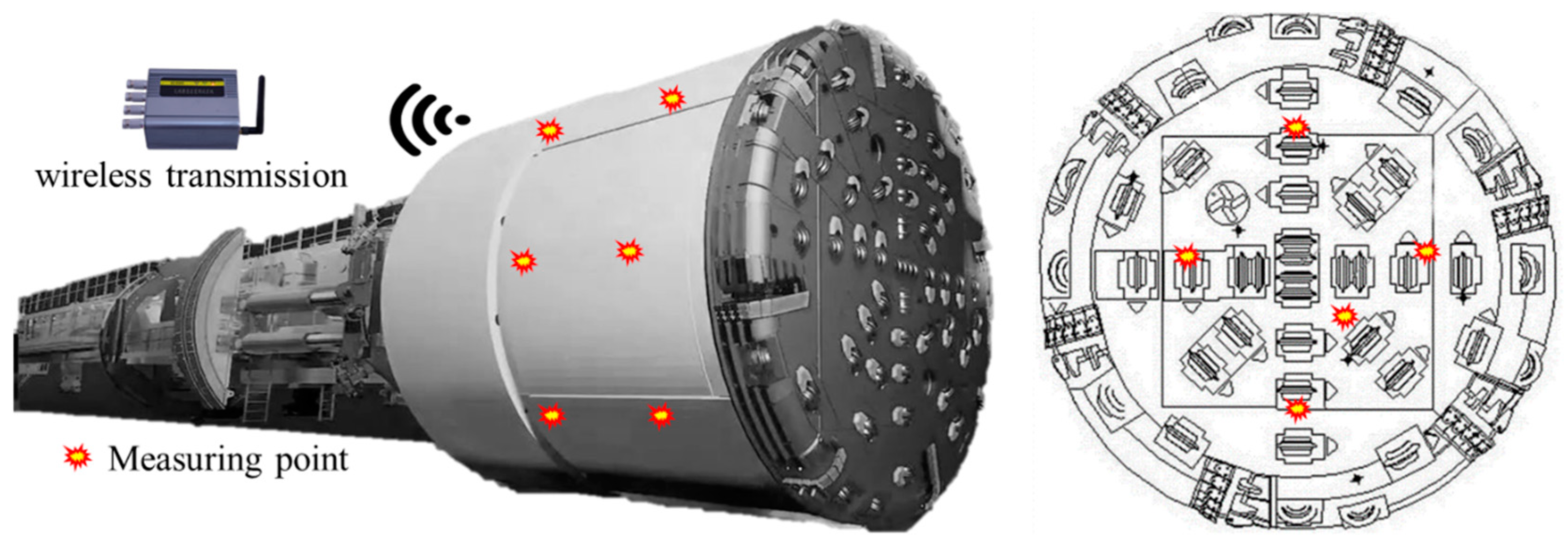
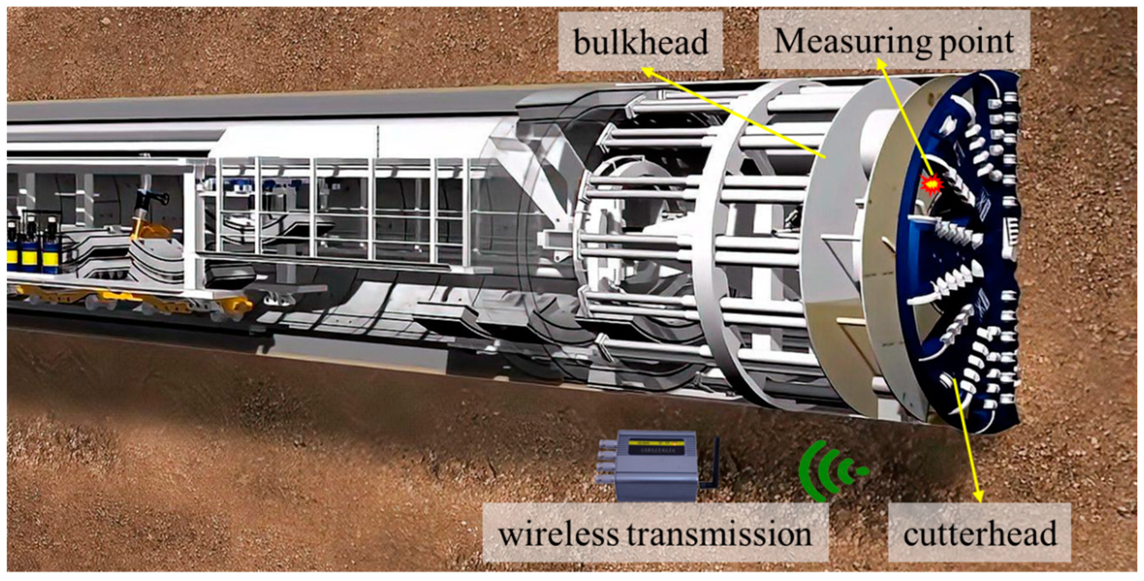
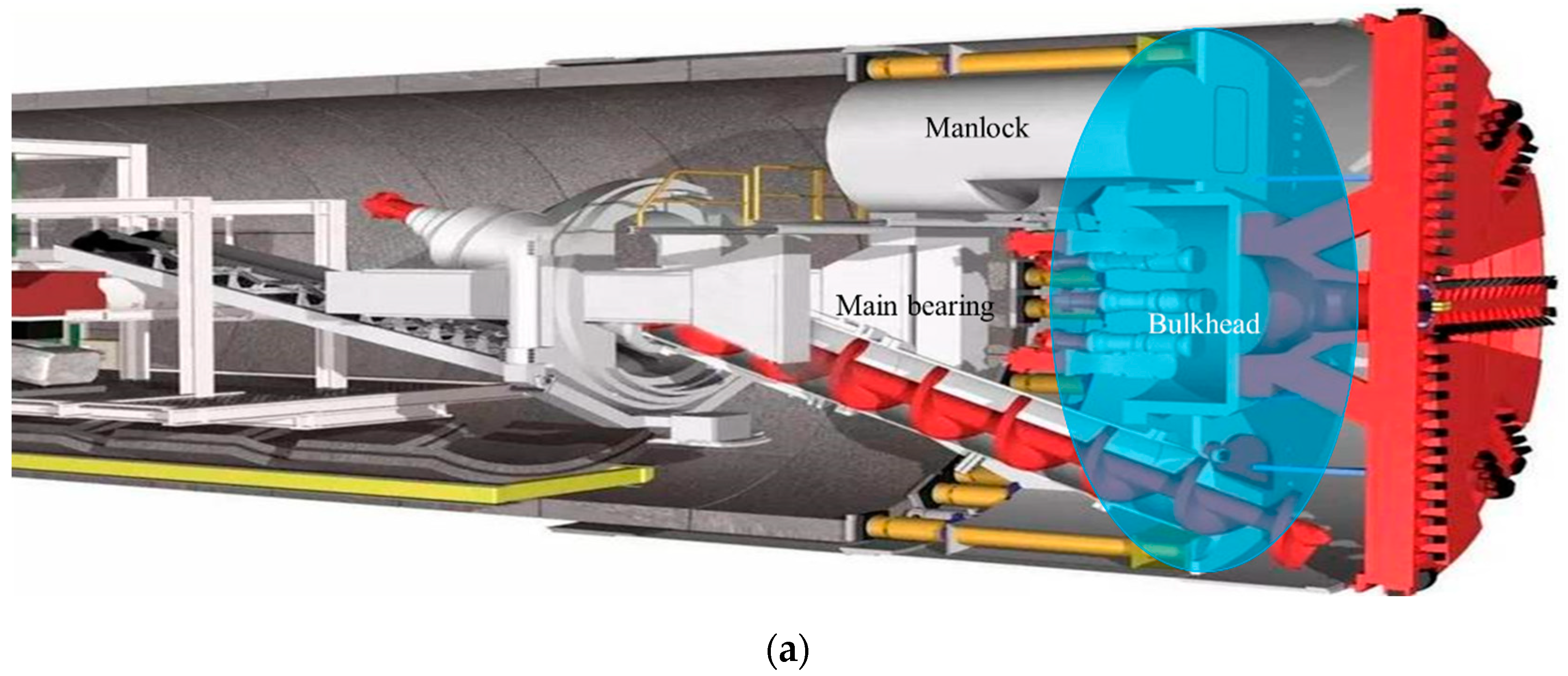
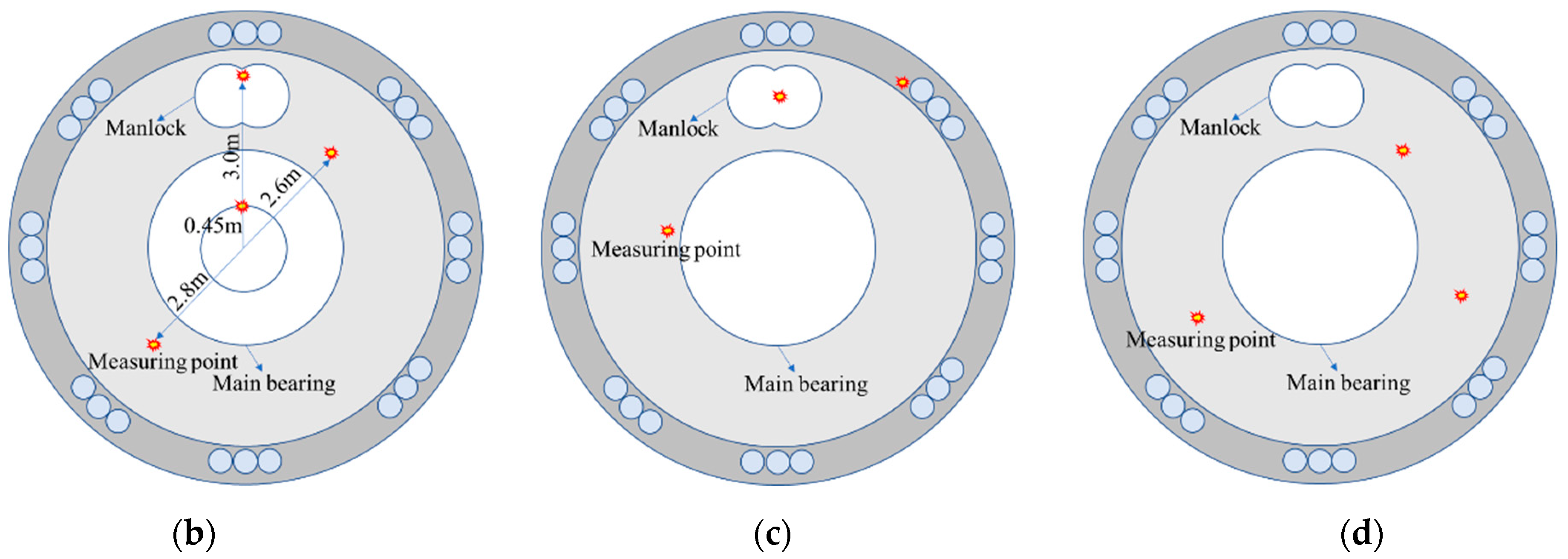
Vibration monitoring methods include direct/indirect monitoring inside the shield machine and monitoring outside the shield machine. The signals collected by the sensors installed on the bulkhead can reflect the vibration characteristics of the cutterhead to a certain extent. Installing sensors on the cutterhead is the most direct and effective method, but it faces the problems of the short life of the sensors and the difficulty of signal transmission. With the development of material properties and communication technology, this problem is expected to be solved. The external monitoring of the shield is mainly based on the relative position of the building and the shield tunnel to determine the monitoring points.
(3)
Processing the raw vibration signals by time–frequency analysis methods can extract the effective feature indexes in them, thus realizing the diagnosis of shield faults, the identification of geological features, and the assessment of the impact on buildings. Signal processing technology seriously affects the ability to extract the hidden information in the signal. Therefore, with the development of information technology, shield vibration signals may be applied in more aspects.
(4)
Intelligent decision-making and automated digging is the ultimate goal in the field of shield construction. The combination of vibration signal and artificial intelligence will be a hotspot for future research. With the rapid development of artificial intelligence technology, vibration signals will certainly play a greater role in the intelligent enhancement of shield tunneling, including intelligent monitoring, intelligent interpretation, intelligent diagnosis, intelligent warning and so on.

Author Contributions

Conceptualization, W.Y. and J.W.; formal analysis, Z.F.; investigation, D.C., Y.Z. and X.B.; resources, J.W.; writing—original draft preparation, W.Y. and Z.F.; writing—review and editing, Z.F.; project administration, W.Y.; funding acquisition, J.W. All authors have read and agreed to the published version of the manuscript.

Funding

This research was supported by the Taishan Scholars Young Experts Programme (No. tsqn202306328), National Natural Science Foundation of China (No. 52378403), Shandong Natural Science Foundation General Project (No. ZR2023ME235), Shandong Excellent Youth Fund (No. ZR2022YQ56), Key A&D Program of Shandong Province, China (No. 2021CXGC010209), and Ministry of Housing and Urban-Rural Development (No. 2020-K-142).

Conflicts of Interest

The authors declare no conflicts of interest.

References

  1. Melis, M.; Medina, L.; Rodriguez, J. Prediction and analysis of subsidence induced by shield tunnelling in the Madrid Metro extension. Can. Geotech. J. 2002, 39, 1273–1287. [Google Scholar] [CrossRef]
  2. Liu, W.; Ding, L. Global sensitivity analysis of influential parameters for excavation stability of metro tunnel. Autom. Constr. 2020, 13, 103080. [Google Scholar] [CrossRef]
  3. Gao, M.; Zhang, N.; Shen, S.; Zhou, A. Real-time dynamic earth-pressure regulation model for shield tunneling by integrating GRU deep learning method with GA optimization. IEEE Access 2020, 8, 64310–64323. [Google Scholar] [CrossRef]
  4. Zhang, J.; Xu, M.; Cui, M.; Xin, Y.; Wang, H.; Su, P. Prediction of Ground Subsidence Caused by Shield Tunnel Construction Under Hidden Karst Cave. Geotech. Geol. Eng. 2022, 40, 3839–3850. [Google Scholar] [CrossRef]
  5. Li, L.; Du, X.; Zhou, J. Numerical Simulation of Site Deformation Induced by Shield Tunneling in Typical Upper-Soft-Lower-Hard Soil-Rock Composite Stratum Site of Changchun. KSCE J. Civ. Eng. 2020, 24, 3156–3168. [Google Scholar] [CrossRef]
  6. Li, L.; Han, Y.; Wang, J.; Jin, Q.; Xiong, Y.; Chong, J.; Ba, X.; Fang, Z.; Wang, K. Study on Critical Safety Distance between the Shield Tunnel and Front Fault Fracture Zone in Urban Metro. Geotech. Geol. Eng. 2022, 40, 5667–5683. [Google Scholar] [CrossRef]
  7. He, X.; Xu, Y.; Shen, S.; Zhou, A. Geological environment problems during metro shield tunnelling in Shenzhen, China. Arab. J. Geosci. 2020, 13, 87. [Google Scholar] [CrossRef]
  8. Qiu, Z.; Yuan, X.; Wang, D.; Fan, S.; Wang, Q. Physical model driven fault diagnosis method for shield Machine hydraulic system. Measurement 2023, 220, 113436. [Google Scholar] [CrossRef]
  9. Zhang, Q.; Hou, Z.; Huang, G.; Cai, Z.; Kang, Y. Mechanical characterization of the load distribution on the cutterhead-ground interface of shield tunneling machines. Tunn. Undergr. Space Technol. 2015, 47, 106–113. [Google Scholar] [CrossRef]
  10. Rostami, J.; Chang, S. A Closer Look at the Design of Cutterheads for Hard Rock Tunnel-Boring Machines. Engineering 2017, 6, 892–904. [Google Scholar] [CrossRef]
  11. Wu, H.; Huo, J.; Meng, Z.; Xue, L.; Xie, L.; Zhang, Z. Load characteristics study with a multi-coupling dynamic model for TBM supporting system based on a field strain test. Tunn. Undergr. Space Technol. 2019, 91, 103016. [Google Scholar] [CrossRef]
  12. Liu, M.; Liao, S.; Yang, Y.; Men, Y.; He, J.; Huang, Y. Tunnel boring machine vibration-based deep learning for the ground identification of working faces. J. Rock Mech. Geotech. Eng. 2021, 13, 1340–1357. [Google Scholar] [CrossRef]
  13. Rallu, A.; Berthoz, N.; Charlemagne, S.; Branque, D. Vibrations induced by tunnel boring machine in urban areas: In situ measurements and methodology of analysis. J. Rock Mech. Geotech. Eng. 2023, 15, 130–145. [Google Scholar] [CrossRef]
  14. Wei, J.; Sun, Q.; Sun, W.; Cai, J.; Zeng, J. Dynamic analysis and load-sharing characteristic of multiple pinion drives in tunnel boring machine. J. Mech. Sci. Technol. 2013, 27, 1385–1392. [Google Scholar] [CrossRef]
  15. Yin, L.; Miao, C.; He, G.; Bai, F.; Gong, Q. Study on the influence of joint spacing on rock fragmentation under TBM cutter by linear cutting test. Tunn. Undergr. Space Technol. 2016, 57, 137–144. [Google Scholar] [CrossRef]
  16. Huo, J.; Wu, H.; Ji, W. Anti-vibration design for TBM main drive system based on multi-directional coupling dynamic characteristics analysis. J. Mech. Sci. Technol. 2020, 34, 4405–4421. [Google Scholar] [CrossRef]
  17. Liu, W.; Zhao, H.; Lin, T.; Gao, B.; Yang, Y. Vibration characteristic analysis of gearbox based on dynamic excitation with eccentricity error. J. Mech. Sci. Technol. 2020, 34, 4545–4562. [Google Scholar] [CrossRef]
  18. Jones, A. A general theory for elastically constrained ball and radial roller bearings under arbitrary load and speed conditions. Trans. ASME 1960, 82, 309–320. [Google Scholar] [CrossRef]
  19. Li, S.; Chen, H.; Ding, H.; Zhang, G.; Shao, J. Modeling method analysis of the friction torque for highspeed spindle bearing. MATEC Web Conf. 2018, 175, 03028. [Google Scholar] [CrossRef]
  20. Yu, J.; Yuan, W.; Li, S.; Yao, W. Assessment of bearing dynamic characteristics by numerical modeling with effects of oil film and centrifugal deformation. Math. Probl. Eng. 2018, 2018, 1619297. [Google Scholar] [CrossRef]
  21. Niu, L.; Cao, H.; Xiong, X. Dynamic modeling and vibration response simulations of angular contact ball bearings with ball defects considering the three-dimensional motion of balls. Tribol. Int. 2017, 109, 26–39. [Google Scholar] [CrossRef]
  22. Wang, L.; Shao, Y. Fault mode analysis and detection for gear tooth crack during its propagating process based on dynamic simulation method. Eng. Fail. Anal. 2017, 71, 166–178. [Google Scholar] [CrossRef]
  23. Nie, Y.; Li, F.; Wang, L.; Li, J.; Sun, M.; Wang, M.; Li, J. A mathematical model of vibration signal for multistage wind turbine gearboxes with transmission path effect analysis. Mech. Mach. Theory 2022, 167, 104428. [Google Scholar] [CrossRef]
  24. Mishra, C.; Samantaray, A.; Chakraborty, G. Ball bearing defect models: A study of simulated and experimental fault signatures. J. Sound Vib. 2017, 400, 86–112. [Google Scholar] [CrossRef]
  25. Furch, J.; Nguyen, T. Simulation of Failure in Gearbox Using MSC. Adams. Acta Univ. Agric. Et Silvic. Mendel. Brun. 2017, 65, 419–428. [Google Scholar] [CrossRef]
  26. Guo, W.; Chen, C.; Xiao, N. Dynamic vibration feature analyses for a two-stage planetary gearbox with a varying crack using a rigid-flexible coupled model. J. Intell. Fuzzy Syst. 2018, 34, 3869–3880. [Google Scholar] [CrossRef]
  27. Zhang, K.; Yu, H.; Liu, Z.; Lai, X. Dynamic characteristic analysis of TBM tunnelling in mixed-face conditions. Simul. Model. Pract. Theory 2010, 18, 1019–1031. [Google Scholar] [CrossRef]
  28. Sun, W.; Ding, X.; Wei, J.; Zhang, A. A method for analyzing sensitivity of multi-stage planetary gear coupled modes to modal parameters. J. Vibroeng. 2015, 17, 3133–3146. [Google Scholar]
  29. Huang, T.; Wang, X.; Liu, H.; Yang, Y. Force analysis of an open TBM gripping-thrusting-regripping mechanism. Mech. Mach. Theory 2016, 98, 101–113. [Google Scholar] [CrossRef]
  30. Chen, G.; Yang, Y.; Huang, T. Vibration analysis of open TBM gripping-thrusting-regripping mechanism. Mech. Mach. Theory 2019, 134, 95–116. [Google Scholar] [CrossRef]
  31. Yang, Y.; Chen, G.; Liu, X.; Huang, T.; Yang, J. Sensitivity analysis of an open TBM gripping-thrusting-regripping mechanism based on the natural characteristics. Mech. Mach. Theory 2019, 139, 1–20. [Google Scholar] [CrossRef]
  32. Li, J.; Kang, B.; Sun, Y.; Huang, Y.; Guo, J.; Gao, Z. Dynamic Characteristic Analysis of the Shield Machine Three-Stage Planetary Reducer Considering Tooth Wear. J. Vib. Eng. Technol. 2023. [Google Scholar] [CrossRef]
  33. Evans, I.; Pomeroy, C. The strength, fracture and workability of Coal. In Pergamon Process; Pergamon Press: London, UK, 1966. [Google Scholar]
  34. Roxborough, F.; Phillips, H. Rock excavation by disc cutter. Int. J. Rock Mech. Min. Sci. Geomech. Abstr. 1975, 12, 361–366. [Google Scholar] [CrossRef]
  35. Sanio, H. Prediction of the performance of disc cutters in anisotropic rock. Int. J. Rock Mech. Min. Sci. Geomech. Abstr. 1985, 22, 153–161. [Google Scholar] [CrossRef]
  36. Rostami, J. Study of pressure distribution within the crushed zone in the contact area between rock and disc cutters. Int. J. Rock Mech. Min. Sci. 2013, 57, 172–186. [Google Scholar] [CrossRef]
  37. Peng, X.; Liu, Q.; Pan, Y.; Lei, G.; Wei, L.; Luo, C. Study on the influence of different control modes on TBM disc cutter performance by rotary cutting tests. Rock Mech. Rock Eng. 2018, 51, 961–967. [Google Scholar] [CrossRef]
  38. Pan, Y.; Liu, Q.; Peng, X.; Liu, Q.; Liu, J.; Huang, X.; Cui, X.; Cai, T. Full-scale linear cutting tests to propose some empirical formulas for TBM disc cutter performance prediction. Rock Mech. Rock Eng. 2019, 52, 4763–4783. [Google Scholar] [CrossRef]
  39. Balci, C. Correlation of rock cutting tests with field performance of a TBM in a highly fractured rock formation: A case study in Kozyatagi-Kadikoy metro tunnel, Turkey. Tunn. Undergr. Space Technol. 2009, 24, 423–435. [Google Scholar] [CrossRef]
  40. Huo, J.; Sun, X.; Li, G.; Li, T.; Sun, W. Multi-degree-of-freedom coupling dynamic characteristic of TBM disc cutter under shock excitation. J. Cent. South. Univ. 2015, 22, 3326–3337. [Google Scholar] [CrossRef]
  41. Huo, J.; Wu, H.; Sun, W.; Zhang, Z.; Wang, L.; Dong, J. Electromechanical coupling dynamics of TBM main drive system. Nonlinear Dyn. 2017, 4, 2687–2710. [Google Scholar] [CrossRef]
  42. Huo, J.; Hou, N.; Sun, W.; Wang, L.; Dong, J. Analyses of dynamic characteristics and structure optimization of tunnel boring machine cutter system with multi-joint surface. Nonlinear Dyn. 2017, 1, 237–254. [Google Scholar] [CrossRef]
  43. Huo, J.; Zhang, Z.; Meng, Z.; Li, J.; Wu, H.; Jia, L. Dynamic analysis and experimental study of a Tunnel boring Machine testbed under multiple conditions. Eng. Fail. Anal. 2021, 127, 105557. [Google Scholar] [CrossRef]
  44. Liao, J.; Zhu, X.; Yao, B. Dynamic modeling of gripper type hard rock tunnel boring machine. Tunn. Undergr. Space Technol. 2018, 71, 166–179. [Google Scholar] [CrossRef]
  45. Sun, H.; Gao, Y. Dynamic Cutting Force Model and Vibration Analysis of the Cutterhead in TBM. Rock Mech. Rock Eng. 2023, 56, 7883–7903. [Google Scholar] [CrossRef]
  46. Xu, H.; Gong, Q.; Zhou, X.; Yang, F.; Han, B. Vibration analysis of rock breaking by TBM rolling cutter assisted with various depth kerfs. Tunn. Undergr. Space Technol. 2024, 146, 105634. [Google Scholar] [CrossRef]
  47. Cho, J.; Jeon, S.; Jeong, H.; Chang, S. Evaluation of cutting efficiency during TBM disc cutter excavation within a Korean granitic rock using linear-cutting-machine testing and photogrammetric measurement. Tunn. Undergr. Space Technol. 2013, 35, 37–54. [Google Scholar] [CrossRef]
  48. Wen, S.; Zhang, C. Experimental and simulation study on rock-breaking efficiency of disc cutters on composite rocks. Int. J. Rock Mech. Min. Sci. 2022, 153, 105089. [Google Scholar] [CrossRef]
  49. Gertsch, R.; Gertsch, L.; Rostami, J. Disc cutting tests in Colorado Red Granite: Implications for TBM performance prediction. Int. J. Rock Mech. Min. Sci. 2007, 44, 238–246. [Google Scholar] [CrossRef]
  50. Tumac, D.; Balci, C. Investigations into the cutting characteristics of CCS type disc cutters and the comparison between experimental, theoretical and empirical force estimations. Tunn. Undergr. Space Technol. 2015, 45, 84–98. [Google Scholar] [CrossRef]
  51. Pan, Y.; Liu, Q.; Liu, J.; Peng, X.; Kong, X. Full-scale linear cutting tests in Chongqing sandstone to study the influence of confining stress on rock cutting forces by TBM disc cutter. Rock Mech. Rock Eng. 2018, 51, 1697–1713. [Google Scholar] [CrossRef]
  52. Xia, Y.; Guo, B.; Tan, Q.; Zhang, X.; Lan, H.; Ji, Z. Comparisons between experimental and semi-theoretical cutting forces of CCS disc cutters. Rock Mech. Rock Eng. 2018, 51, 1583–1597. [Google Scholar] [CrossRef]
  53. Dehkhoda, S.; Detournay, E. Rock cutting experiments with an actuated disc. Rock Mech. Rock Eng. 2019, 52, 3443–3458. [Google Scholar] [CrossRef]
  54. Thyagarajan, M.; Rostami, J. Study of cutting forces acting on a disc cutter and impact of variable penetration measured by full scale linear cutting tests. Int. J. Rock Mech. Min. Sci. 2024, 175, 105675. [Google Scholar] [CrossRef]
  55. Geng, Q.; Wei, Z.; Meng, H.; Macias, F.; Bruland, A. Free-face-assisted rock breaking method based on the multi-stage tunnel boring machine (TBM) cutterhead. Rock Mech. Rock Eng. 2016, 49, 4459–4472. [Google Scholar] [CrossRef]
  56. Gong, Q.; Du, X.; Li, Z.; Wang, Q. Development of a mechanical rock breakage experimental platform. Tunn. Undergr. Space Technol. 2016, 57, 129–136. [Google Scholar] [CrossRef]
  57. Pan, Y.; Liu, Q.; Peng, X.; Kong, X.; Liu, J.; Zhang, X. Full-Scale rotary cutting test to study the influence of disc cutter installment radius on rock cutting forces. Rock Mech. Rock Eng. 2018, 51, 2223–2236. [Google Scholar] [CrossRef]
  58. Deng, L.; Zhang, F.; Li, X.; Zhang, C.; Ji, Y.; Wu, Y. Experimental and Numerical Investigations on Rock Breaking of TBM Disc Cutter Based on a Novel Platform with Rotational Cutting. Rock Mech. Rock Eng. 2023, 56, 1415–1436. [Google Scholar] [CrossRef]
  59. Liu, H.; Kou, S.; Lindqvist, P.; Tang, C. Numerical simulation of the rock fragmentation process induced by indenters. Int. J. Rock Mech. Min. Sci. 2022, 39, 491–505. [Google Scholar] [CrossRef]
  60. Zhai, S.; Zhou, X.; Bi, J.; Qian, Q. Validation of GPD to Model Rock Fragmentation by TBM Cutters. Int. J. Geomech. 2017, 17, 06016036. [Google Scholar] [CrossRef]
  61. Xiao, N.; Zhou, X.; Gong, Q. The modelling of rock breakage process by TBM rolling cutters using 3D FEM-SPH coupled method. Tunn. Undergr. Space Technol. 2017, 61, 90–103. [Google Scholar] [CrossRef]
  62. Wu, Z.; Zhang, P.; Fan, L.; Liu, Q. Numerical study of the effect of confining pressure on the rock breakage efficiency and fragment size distribution of a TBM cutter using a coupled FEM-DEM method. Tunn. Undergr. Space Technol. 2019, 88, 260–275. [Google Scholar] [CrossRef]
  63. Cheng, J.; Jiang, Z.; Han, W.; Li, M.; Wang, Y. Breakage mechanism of hard-rock penetration by TBM disc cutter after high pressure water jet precutting. Eng. Fract. Mech. 2020, 240, 107320. [Google Scholar] [CrossRef]
  64. Fang, Y.; Yao, Z.; Xu, W.; Tian, Q.; He, C.; Liu, S. The performance of TBM disc cutter in soft strata: A numerical simulation using the three-dimensional RBD-DEM coupled method. Eng. Fail. Anal. 2021, 119, 104996. [Google Scholar] [CrossRef]
  65. Afrasiabi, N.; Rafiee, R.; Noroozi, M. Investigating the effect of discontinuity geometrical parameters on the TMB performance in hard rock. Tunn. Undergr. Space Technol. 2019, 84, 326–333. [Google Scholar] [CrossRef]
  66. Li, T.; Zhang, Z.; Jia, C.; Liu, B.; Liu, Y.; Jiang, Y. Investigating the cutting force of disc cutter in multi-cutter rotary cutting of sandstone: Simulations and experiments. Int. J. Rock Mech. Min. Sci. 2022, 152, 105069. [Google Scholar] [CrossRef]
  67. Yu, Q.; He, X.; Miao, H.; Lin, M.; Zhang, X.; Guo, R. Numerical simulation of rock breaking by TBM disc cutter in soil-rock composite formations. Bull. Eng. Geol. Environ. 2022, 81, 514. [Google Scholar] [CrossRef]
  68. Shang, X.; Zhou, J.; Liu, F.; Shen, J.; Liao, X. A peridynamics study for the free-surface-assisted rock fragmentation caused by TBM disc cutters. Comput. Geotech. 2023, 158, 105380. [Google Scholar] [CrossRef]
  69. Yang, Z.; Pan, D.; Zhou, J.; Chen, J.; Sun, Z.; Liu, H. Vibration characteristics of cutter-head in soft-hard mixed stratum: An experimental case study on su’ai tunnel. KSCE J. Civ. Eng. 2020, 24, 1338–1347. [Google Scholar] [CrossRef]
  70. Ling, J.; Sun, W.; Yang, X.; Tong, X.; Zhang, N. Vibration response and parameter influence of TBM cutterhead system under extreme conditions. J. Mech. Sci. Technol. 2018, 32, 4959–4969. [Google Scholar] [CrossRef]
  71. Huang, X.; Liu, Q.; Liu, H.; Zhang, P.; Pan, S.; Zhang, X.; Fang, J. Development and in-situ application of a real-time monitoring system for the interaction between TBM and surrounding rock. Tunn. Undergr. Space Technol. 2018, 81, 187–208. [Google Scholar] [CrossRef]
  72. Wu, F.; Gong, Q.; Li, Z.; Qiu, H.; Jin, C.; Huang, L.; Yin, L. Development and application of cutterhead vibration monitoring system for TBM tunneling. Int. J. Rock Mech. Min. Sci. 2021, 146, 104887. [Google Scholar] [CrossRef]
  73. Liu, D.; Xiao, Y.; Zhou, X.; Gong, Q.; Liu, J. Study on Vibration Characterization Parameters of TBM Rock-breaking Cutterhead. Mod. Tunn. Technol. 2023, 60, 153–162. (In Chinese) [Google Scholar]
  74. Walter, B. Detecting Changing Geologic Conditions with Tunnel Boring Machines by Using Passive Vibration Measurements. Ph.D. Thesis, Colorado School of Mines, Golden, CO, USA, 2013. [Google Scholar]
  75. Buckley, J. Monitoring the Vibration Response of a Tunnel Boring Machine: Application to Real Time Boulder Detection. MSc Thesis, Colorado School of Mines, Golden, CO, USA, 2014. [Google Scholar]
  76. Xin, S.; Zhou, Y.; Zhang, M.; Li, L. Research and development of shield-/TBM dedicated vibration monitoring sensor VM-BOX. Tunn. Constr. 2018, 213, 197–202. (In Chinese) [Google Scholar]
  77. Liu, M.; Liao, S.; Men, Y.; Xing, H.; Liu, H.; Sun, L. Field Monitoring of TBM Vibration During Excavating Changing Stratum: Patterns and Ground Identification. Rock Mech. Rock Eng. 2022, 55, 1481–1498. [Google Scholar] [CrossRef]
  78. Fang, Y.; Li, X.; Liu, H.; Hao, S.; Yi, Y.; Guo, Y.; Li, H. Intelligent real-time identification technology of stratum characteristics during slurry TBM tunneling. Tunn. Undergr. Space Technol. 2023, 139, 105216. [Google Scholar] [CrossRef]
  79. Shen, S.; Yan, T.; Zhou, A. Estimating locations of soil–rock interfaces based on vibration data during shield tunneling. Autom. Constr. 2023, 150, 104813. [Google Scholar] [CrossRef]
  80. Lu, Z.; Wang, X.; Zhou, G.; Feng, L. Investigation on Vibration Influence Law of Double-Shield TBM Tunnel Construction. Appl. Sci. 2022, 12, 7727. [Google Scholar] [CrossRef]
  81. Wu, K.; Zheng, Y.; Li, S.; Sun, J.; Han, Y.; Hap, D. Vibration response law of existing buildings affected by subway tunnel boring machine excavation. Tunn. Undergr. Space Technol. 2022, 120, 104318. [Google Scholar] [CrossRef]
  82. Wang, Z.; Jiang, Y.; Shao, X.; Liu, C. On-site measurement and environmental impact of vibration caused by construction of double-shield TBM tunnel in urban subway. Sci. Rep. 2023, 13, 17689. [Google Scholar] [CrossRef]
  83. Yang, Y.; Du, L.; Li, Q.; Zhao, X.; Ni, Z. Vibration prediction and analysis of the main beam of the TBM based on a multiple linear regression model. Sci. Rep. 2024, 14, 3498. [Google Scholar] [CrossRef] [PubMed]
  84. Tao, H.; Wang, P.; Chen, Y.; Stojanovic, V.; Yang, H. An unsupervised fault diagnosis method for rolling bearing using STFT and generative neural networks. J. Frankl. Inst. 2020, 357, 7286–7307. [Google Scholar] [CrossRef]
  85. Kong, Y.; Wang, T.; Chu, F. Meshing frequency modulation assisted empirical wavelet transform for fault diagnosis of wind turbine planetary ring gear. Renew. Energy 2019, 132, 1373–1388. [Google Scholar] [CrossRef]
  86. Kirikera, G.; Shinde, V.; Schulz, M.; Ghoshal, A.; Sundaresan, M.; Allemang, R.; Lee, J. A structural neural system for real-time health monitoring of composite materials. Struct. Health Monit. 2008, 7, 65–83. [Google Scholar] [CrossRef]
  87. Randall, R. Vibration-based condition monitoring: Industrial, aerospace and automotive applications. Mech. Mach. Sci. 2010, 3, 431–477. [Google Scholar]
  88. Huang, N.; Long, S.; Wu, M.; Shih, H.; Zheng, Q.; Yen, N.; Tung, C.; Liu, H.; Shen, Z. The empirical mode decomposition and the hilbert spectrum for nonlinear and non-stationary time series analysis. Proc. R. Soc. Math. Phys. Eng. Sci. 1998, 454, 903–995. [Google Scholar] [CrossRef]
  89. Dragomiretskiy, K.; Zosso, D. Variational Mode Decomposition. IEEE Trans. Signal Process. 2014, 62, 531–544. [Google Scholar] [CrossRef]
  90. Ville, J. Theorie et application dela notion de signal analytique. Cables Et Transm. 1948, 2, 61–74. [Google Scholar]
  91. Huang, N.; Shen, Z.; Long, S. A New View of Nonlinear Water Waves: The Hilbert Spectrum1. Annu. Rev. Fluid Mech. 2003, 31, 417–457. [Google Scholar] [CrossRef]
  92. Smith, J. The local mean decomposition and its application to EEG perception data. J. R. Soc. Interface 2005, 2, 443–454. [Google Scholar] [CrossRef]
  93. Mark, G.; Frei, I. Intrinsic Time-Scale Decomposition: Time-Frequency-Energy Analysis and Real-Time Filtering of Non-Stationary Signals. Proc. Math. Phys. Eng. Sci. 2007, 463, 321–342. [Google Scholar]
  94. Li, J.; Jing, L.; Zheng, X.; Li, P.; Yang, C. Application and outlook of information and intelligence technology for safe and efficient TBM construction. Tunn. Undergr. Space Technol. 2019, 93, 103097. [Google Scholar] [CrossRef]
  95. Han, Y. State detects and fault diagnosis technology of TBM. Constr. Mach. 2003, 9, 30–34. (In Chinese) [Google Scholar]
  96. Zhao, H.; Su, D.; Qiao, W. The status monitoring and failure diagnosis of TBM main gearbox. Constr. Mach. 2003, 6, 44–46. (In Chinese) [Google Scholar]
  97. Ling, J.; Tong, X.; Guo, C.; Li, Z. Natural frequency sensitivity and influence analysis of TBM cutterhead system. J. Vibroeng. 2019, 21, 1710–1723. [Google Scholar] [CrossRef]
  98. Zou, X.; Mi, Y.; Zheng, H.; Tao, J. Influence of vibration on the performance of tunnel boring machines. In Proceedings of the 2016 12th IEEE/ASME International Conference on Mechatronic and Embedded Systems and Applications (MESA), Auckland, New Zealand, 29–31 August 2016. [Google Scholar]
  99. Zhu, Y.; Wang, X.; Chen, X. Evaluation of TBM Cutterhead’s Comprehensive Performance Under Complicated Conditions. J. Beijing Inst. Technol. 2020, 29, 326–338. [Google Scholar]
  100. Sun, W.; Zhu, Y.; Wang, W.; Zhu, D. Evaluation of TBM cutterhead vibration under complicated condition. In Proceedings of the 2016 12th IEEE/ASME International Conference on Mechatronic and Embedded Systems and Applications (MESA), Auckland, New Zealand, 29–31 August 2016. [Google Scholar]
  101. Shao, H.; Jiang, H. A novel method for intelligent fault diagnosis of rolling bearings using ensemble deep auto-encoders. Mech. Syst. Signal Process. 2018, 102, 278–297. [Google Scholar] [CrossRef]
  102. Lu, C.; Chen, J.; Hong, R.; Feng, Y.; Li, Y. Degradation trend estimation of slewing bearing based on LSSVM model. Mech. Syst. Signal Process. 2016, 76–77, 353–366. [Google Scholar] [CrossRef]
  103. Pan, Y.; Hong, R.; Chen, J.; Qin, Z.; Feng, Y. Incipient fault detection of wind turbine large-size slewing bearing based on circular domain. Measurement 2019, 137, 130–142. [Google Scholar] [CrossRef]
  104. Bao, W.; Wang, H.; Chen, J.; Zhang, B.; Ding, P.; Wu, J.; He, P. Life prediction of slewing bearing based on isometric mapping and fuzzy support vector regression. Trans. Inst. Meas. 2019, 42, 94–103. [Google Scholar] [CrossRef]
  105. Zhang, C.; Meng, X.; Li, D.; Wu, C.; Sun, H. Design and Study of Online Automatic Monitoring System for Shield Vibration. Tunn. Constr. 2018, 38, 321–328. [Google Scholar]
  106. Fang, Y.; Li, X.; Guo, Y.; Jin, D.; Liu, H. Effects of Driving Parameters on TBM Dynamic Response and Cracking of the Disc Cutter Ring: A Case Study. Rock Mech. Rock Eng. 2024. [Google Scholar] [CrossRef]
  107. Fang, Y.; Li, X.; Hao, S.; Liu, H.; Yang, Y.; Guo, Y. Failure analysis of slurry TBM discharge pipe in complex strata combined with wear and vibration characteristics. Eng. Fail. Anal. 2023, 150, 107307. [Google Scholar] [CrossRef]
  108. Mooney, M.; Walter, B.; Steele, J.; Cano, D. Influence of geological conditions on measured TBM vibration frequency. In North American Tunneling; Davidson, G., Howard, A., Jacobs, L., Pintabona, R., Zernich, B., Eds.; North American Tunneling 2014 Proceedings; Society for Mining, Metallurgy & Exploration: Englewood, CO, USA, 2014; pp. 32–41. [Google Scholar]
  109. Ates, U.; Copur, H.; Mamaghani, A.; Avunduk, E.; Binen, I. Investigation of vibration patterns occurred during TBM excavation and rock cutting tests. In Proceedings of the ISRM 2019 Rock Dynamics Summit, Okinawa, Japan, 7–11 May 2019; pp. 704–709. [Google Scholar]
  110. Ates, U.; Copur, H. Investigation of parameters affecting vibration patterns generated during excavation by EPB TBMs. Tunn. Undergr. Space Technol. 2023, 138, 105185. [Google Scholar] [CrossRef]
  111. Vogiatzis, K.; Zafiropoulou, V.; Mouzakis, H. Monitoring and assessing the effects from Metro networks construction on the urban acoustic environment: The Athens Metro Line 3 Extension. Sci. Total Environ. 2018, 639, 1360–1380. [Google Scholar] [CrossRef] [PubMed]
  112. Ocak, I. Environmental effects of tunnel excavation in soft and shallow ground with EPBM: The case of Istanbul. Environ. Earth Sci. 2009, 59, 347–352. [Google Scholar] [CrossRef]
  113. Ding, L.; Wu, X.; Zhang, L.; Skibniewski, M. How to protect historical buildings against tunnel-induced damage: A case study in China. J. Cult. Herit. 2015, 16, 904–911. [Google Scholar] [CrossRef]
  114. Sengupta, A.; Banerjee, R.; Bandyopadhyay, S. Estimation of ground vibration and settlement during underground tunneling in Kolkata, India. Arab. J. Geosci. 2021, 14, 39. [Google Scholar] [CrossRef]
  115. Guo, F.; Tao, L.; Kong, H.; Ma, H.; Zhang, L.; Zhang, X. Analysis of vibration propagation and attenuation characteristics of shield tunnel construction in Lanzhou sandy gravel stratum. Rock Soil. Mech. 2018, 39, 3377–3384. (In Chinese) [Google Scholar]
  116. Zhu, J.; Deng, Z.; Yuan, F.; Yuan, Z.; Wang, Z. Investigations on main influencing factors on vibrations of tunnel boring machine in composite ground. J. Zhejiang Univ. Technol. 2022, 50, 436–443. (In Chinese) [Google Scholar]
  117. Namli, M.; Aras, F. Investigation of effects of dynamic loads in metro tunnels during construction and operation on existing buildings. Arab. J. Geosci. 2020, 13, 424. [Google Scholar] [CrossRef]
  118. Grund, M.; Ritter, J.; Gehrig, M. Ground Motion Relations While TBM Drilling in Unconsolidated Sediments. Rock Mech. Rock Eng. 2016, 49, 1773–1787. [Google Scholar] [CrossRef]
  119. Morgese, M.; Domaneschi, M.; Ansari, F.; Cimellaro, G.; Inaudi, D. Improving Distributed Fiber-Optic Sensor Measures by Digital Image Correlation: Two-Stage Structural Health Monitoring. ACI Struct. J. 2021, 118, 91–102. [Google Scholar]
  120. Domaneschi, M.; Niccolini, G.; Lacidogna, G.; Cimellaro, G. Nondestructive monitoring techniques for crack detection and localization in RC elements. Appl. Sci. 2020, 10, 3248. [Google Scholar] [CrossRef]
  121. Mitoulis, S.; Domaneschi, M.; Cimellaro, G.; Casas, J. Bridge and transport network resilience—A perspective. Proc. Inst. Civ. Eng.-Bridge Eng. 2022, 175, 138–149. [Google Scholar] [CrossRef]
  122. Mitoulis, S.; Domaneschi, M.; Casas, J.; Cimellaro, G.; Catbas, N.; Stojadinovic, B.; Frangopol, D. Editorial: The crux of bridge and transport network resilience—Advancements and future-proof solutions. Proc. Inst. Civ. Eng.-Bridge Eng. 2022, 175, 133–137. [Google Scholar] [CrossRef]
  123. Pellecchia, C.; Cardoni, A.; Cimellaro, G.; Domaneschi, M.; Ansari, F.; Khalil, A. Progressive Collapse Analysis of the Champlain Towers South in Surfside, Florida. J. Struct. Eng. 2023, 150, 1. [Google Scholar] [CrossRef]
  124. Domaneschi, M.; Cucuzza, R.; Martinelli, L.; Noori, M.; Marano, G. A probabilistic framework for the resilience assessment of transport infrastructure systems via structural health monitoring and control based on a cost function approach. Struct. Infrastruct. Eng. 2024, 1–13. [Google Scholar] [CrossRef]
  125. Cucuzza, R.; Aloisio, A.; Bari, R.; Domaneschi, M. Vulnerability assessment and lifecycle analysis of an existing masonry arch bridge. Eng. Struct. 2024, 302, 117422. [Google Scholar] [CrossRef]
Figure 1. The schematic diagram of shield vibration propagation.
Buildings 14 01066 g001
Figure 2. The main bearing and gearbox of the shield machine.
Buildings 14 01066 g002
Figure 3. The disc cutter cuts rock test system. (a) Linear cutting test; (b) rotary cutting test.
Buildings 14 01066 g003
Figure 4. Vibration monitoring program in Ref. [70].
Buildings 14 01066 g004
Figure 5. Vibration monitoring program in Ref. [71].
Buildings 14 01066 g005
Figure 6. Vibration monitoring program in Ref. [72].
Buildings 14 01066 g006
Figure 7. Vibration monitoring program. (a) Schematic diagram of shield machine, (b) monitoring points in Ref. [12], (c) monitoring points in Ref. [78], and (d) monitoring points in Ref. [79].
Buildings 14 01066 g007aBuildings 14 01066 g007b
Figure 8. Measuring point layout of vibration monitoring in Ref. [80].
Buildings 14 01066 g008
Figure 9. Measuring point layout of vibration monitoring in Ref. [13].
Buildings 14 01066 g009
Disclaimer/Publisher’s Note: The statements, opinions and data contained in all publications are solely those of the individual author(s) and contributor(s) and not of MDPI and/or the editor(s). MDPI and/or the editor(s) disclaim responsibility for any injury to people or property resulting from any ideas, methods, instructions or products referred to in the content.

