Article

Compressive and Bonding Performance of GFRP-Reinforced Concrete Columns

Department of Civil Engineering, College of Engineering, Qassim University, Buraidah 52571, Saudi Arabia
*
Author to whom correspondence should be addressed.
Buildings 2024, 14(4), 1071; https://doi.org/10.3390/buildings14041071
Submission received: 9 March 2024 / Revised: 3 April 2024 / Accepted: 9 April 2024 / Published: 12 April 2024
(This article belongs to the Section Building Materials, and Repair & Renovation)

Abstract

:
The use of glass-fiber-reinforced polymer (GFRP) bars as an alternative to steel bars for reinforcing concrete (RC) structures has gained increasing attention in recent years. GFRP bars offer several advantages over steel bars, such as corrosion resistance, lightweight, high tensile strength, and non-magnetic properties. However, there are also some challenges and uncertainties associated with the behavior and performance of GFRP-reinforced concrete (GFRP-RC) structures, especially under compression and bonding behavior. Therefore, there is a need for comprehensive experimental investigations to validate the effectiveness of GFRP bars in concrete columns. This paper presents a study that aims to address these issues by conducting experimental tests on GFRP-RC columns. The experimental tests examine the mechanical properties of GFRP bars and their bond behavior with concrete, as well as the axial compressive behavior of GFRP-RC columns with different reinforcement configurations, tie spacing, and bar sizes. The findings reveal that GFRP bars demonstrate a comparable, if not superior, compressive capacity to traditional steel bars, significantly contributing to the load-bearing capacity of concrete columns. The study concludes with a set of recommendations for further exploration, underscoring the potential of GFRP bars in revolutionizing the construction industry.

1. Introduction

The realm of construction engineering is witnessing a shift with the introduction of glass-fiber-reinforced polymer (GFRP) bars as reinforcement for concrete members. This research presents a study to verify the effectiveness of using GFRP reinforcing bars in concrete columns as an alternative to the conventional steel bars. GFRP bars offer several advantages over steel bars, such as corrosion resistance, lightweight, high tensile strength, and non-magnetic properties. However, there are also some challenges and uncertainties associated with the behavior and performance of GFRP-reinforced concrete (GFRP-RC) structures, especially under compression, and bonding behavior. Even though extensive research studies in the literature have examined the behavior of reinforced concrete members reinforced with GFRP bars, most of these studies have focused on the flexural and shear behaviors in beams and slabs where internal stresses on the GFRP bars are tensile stresses. This is important since it is well-established in several research studies that the compressive strength of GFRP bars is about 50 to 77% of their tensile strength [1,2,3,4]. Therefore, this variation in strength raises concerns regarding the reliability of using GFRP bars as reinforcements in concrete columns where compression dominates the response such as in columns of typical residential and office buildings. This work is a continuation of limited studies evaluating the performance of such a type of column in an effort to ease design codes and specifications governing the design of GFRP-reinforced concrete columns. The research also investigates related factors that may affect the structural integrity of these critical structural members by examining the bond behavior of GFRP bars in concrete and their durability.

2. Literature Review

2.1. Properties of Steel and GFRP Rebars

Design codes of reinforced concrete structures specify standard specifications for reinforcing bars. The ACI 318 [5], SBC 304 [6] and AASHTO LRFD [7] design codes require that steel reinforcement is in accordance with ASTM A615 [8] and ASTM A706 [9] specifications. Typically, the behavior of reinforcing steel bars is characterized by a small elastic region followed by a significantly larger plastic region and, hence, they possess high ductility and toughness capacities compared to other materials [10,11]. The extent of the plastic region mainly depends on the yield strength (grade) of the steel bar. The higher the yield strength, the shorter the plateau region. For bars with high-strength steel, there is no well-defined yielding point and, hence, no plateau region [11,12]. The elastic modulus of steel reinforcing bars, Es, is about 200 GPa, and this value is uniformly considered in reinforced concrete deign codes. The yield strength typically ranges from 250 to 700 MPa. ASTM A615 [8] and ASTM A706 [9] limit the minimum yield strength to 276 MPa and 414 MPa, respectively. The ASTM A706 [9] limits the maximum yield strength to 540 MPa, which is intended for seismic design applications where ductility and imposed limitations on strength is of significant importance [12,13,14].
Even though GFRP bars have favorable properties when used as a flexural tension reinforcement, some properties need to be explored when used for compression members such as columns, piles, and bridge pier columns, which are used to transmit the compression load. Many studies have shown the effectiveness of using GFRP bars either for solid or hollow concrete columns; however, it has been indicated that the strength and modulus of GFRP in compression are lower than in tension [2]. The compressive strength of 55% tensional strength is reported for GFRP [1,2]. Deitz et al. [3] tested 45 GFRP bar samples under compression, and the results showed that the compressive strength was approximately 50% of the tensile strength. Chaallal and Benmokrane [4] tested the GFRP’s compressive behavior for three different bar diameters and reported that the average compressive strength was 77% of tensile strength.

2.2. Structural Behavior of Concrete Columns Reinforced with Steel and GFRP Bars

GFRP bars are an effective substitute for steel rebars in reinforced concrete structures that are exposed to severe environments due to their non-corrosive properties and high strength. Studies on concrete structures that are reinforced in the longitudinal and transversal direction using GFRP bars showed satisfactory performance in bending and shear [15,16,17,18]. Furthermore, other studies conducted experimental work on this type of reinforcement and reported the mechanical properties [19,20,21,22,23,24,25,26], physical properties [3], chemical properties [19,25,27], thermal characteristics [21,26,28], and durability properties [20,29]. These studies have been specified in CSA S807 [30], ASTM D7957 [31] material specification, and design codes to verify the quality, design, and safety of these reinforcing materials to be used as structural reinforcement. Therefore, it is used in many engineering construction projects including bridges, highways, boat ramps, and concrete pavements.
Studies have also been conducted to examine the performance of the GFRP reinforcements when used in concrete columns. Taerwe [32] reported that the results are 30% to 40% of their tensile strength for bars embedded in concrete prisms. Paramanantham [33] tested 14 concrete beams and columns with dimensions of 200 × 200 × 1800 mm where GFRP bars were used. The study reported that the bars would only be stressed up to 20% to 30% of the ultimate strength. The effect of replacing steel bars with GFRP bars was investigated by Alsayed et al. [34] using an equal number of longitudinal bars and ties of 15 samples of 450 × 250 × 1200 mm columns under compression. Results showed that GFRP bars reduced the capacity by 13%, irrespective of longitudinal steel bars. Replacing steel ties with GFRP ties reduced the capacity by 10%. Lotfy [35] tested square GFRP-reinforced concrete using different reinforcement ratios and reported that an increase in reinforcement ratio increases the column ductility. Tobbi et al. [36] also studied square columns reinforced with GFRP and found that the column nominal capacity can be calculated considering that the compressive strength of bars is equal to 35% of its tensile strength. AlAjarmeh et al. [15] investigated the compressive behavior of circular bars with 12.7 mm-, 15.9 mm-, and 19.1 mm-diameter GFRP bars in concrete columns. The results are consistent with Maranan et al.’s [23] study wherein GFRP bars failed by crushing the lower spiral spacing, with the results indicating that the unsupported length has a major effect on compression and required more studies.
Previous research work indicates that the compression behavior of GFRP reinforcement has been subjected to significant variation and test data were scattered. However, there is a consensus that it has a lower compression strength than tensile strength. To date, only a few studies have studied the behavior of concrete columns reinforced with GFRP bars and ties or spirals. In addition, ACI 440 recommends not to rely on GFRP as longitudinal reinforcement in columns or as compression reinforcement in flexural members. Code writing bodies in the United States and Canada have tasked many committees to produced standards and guidelines for elements reinforced with GFRP including AASHTO [37], ACI 440-1R [38], CSA S806 [30], and CSA S6 [39]. Developing a recommendation and design provisions for compressive members requires an understanding of the material characteristics to streamline the shift from the steel design to GFRP, by first establishing limits comparable to that of steel columns, which should be based on stress–strain laws, and then reviewing performance and experimental results. Especially in the past 10 years, GFRP bars embedded in concrete columns have been the spotlight of civil engineering research. Many different parameters are included in experimental and analytical studies converting a wide range of topics.
The reinforcing GFRP bar in columns was studied in many experimental studies in the last period and mentioned previously, which led to the introduction of several theoretical and numerical models to estimate the nominal axial compressive force (Pn) of concrete columns reinforced with GFRP bars. Table 1 shows a summary of these models. The existing tests and proposed model confirmed that when the axial capacity of the longitudinal GFRB bars is ignored, the overall capacity of the column is underestimated [40]. Developing a recommendation and design provisions for compressive members requires an understanding of the material characteristics to streamline the shift from the steel design to GFRP, by first establishing limits comparable to that of steel columns, which should be based on stress–strain laws, and then reviewing performance and experimental results.

2.3. Bond Behavior of Steel and GFRP Rebars in Concrete

Reinforcing bars transfer loads between concrete and steel through a process known as bonding. Bonding is the adhesion between the concrete and the reinforcing steel, which allows the two materials to work together to resist applied loads. The surface of reinforcing bars is deformed with a continuous series of ribs or indentations to promote a better bond with the concrete and reduce the risk of slippage [13]. The bond behavior of reinforcing steel bars in concrete is a critical aspect of the structural behavior of reinforced concrete members. Bond strength is the property that builds adhesion between concrete and its adjacent reinforcement bars, making it a key factor in the structural behavior of concrete [47]. The bond between steel and concrete has an important influence on the behavior of reinforced elements in the cracked stage. Crack widths and deflections are influenced by the distribution of bond stresses along the reinforcement bars and by the slip between the bar and the surrounding concrete [48]. Bond strength is affected by many factors, including the surface preparation or condition of the reinforcing bar, such as bar coatings [49]. For example, epoxy coatings have been shown to reduce bond strength, with epoxy coated bars exhibiting a bond strength up to 32% lower than uncoated bars [47]. The bond strength of bars does not depend greatly on the value of concrete strength but rather on the surface characteristics of bars [50]. Concrete with higher strength has a stronger bond between the paste and the aggregate, leading to improvements in the bond strength of concrete [51]. However, it is important to note that other factors such as the surface preparation and condition of the reinforcing bar can also affect the bond strength [52]. The enhancements in mechanical properties of concrete are found to substantially influence the bond performance between concrete and rebar [53]. Degradation of the rebar–concrete bond intact in reinforced concrete members may lead to a localized failure in the contact area around the rebar. This may occur due to the low capacity in the tension ring stresses in the concrete zone as a result of pulling in reinforcement [50]. Thus, an increase in the tensile strength of concrete may lead to an improved bond response.
The bond between the bars and concrete is a critical parameter affecting reinforced concrete’s serviceability, cracking behavior, and ultimate capacity. It is known that GFRP has the advantage of high tensile strength, lightweight, and satisfactory durability in aggressive environmental conditions. It was introduced as a competitive alternative to traditional steel bars for different concrete structures. However, GFRP has inherited orthotropic material properties due to the manufacturing process, which is different from steel bars’ isotropic properties [54]. In addition, GFRP exhibits linear elastic behavior up to failure, making it lack ductility compared to steel rebar. Existing studies available in the literature have revealed a significant issue that the bond behavior of GFRP bars to concrete is weaker than of steel rebars [55]. It was reported that the bond strength of GFRP is up to 60% lower than the strength of corresponding steel bars; this is because steel has a deformed surface with ribs, which increases the mechanical interaction with concrete [56]. Correspondingly, surface treatment methods, such as spiral formation and sand coating, have been used to produce a deformed or roughened surface on GFRP bars, significantly increasing the bond strength [54]. Okelo and Yuan [57] investigated GFRP bond behavior bars through pull-out tests. Surface treatment methods were applied, which include sand coating, surface texture, helical wrapping with sand coating, dep dents or grooves, and defamation by resin. Their results showed that the deformed surface, similar to that of steel rebars, achieved the best bond performance compared with other surface treatment methods; however, the bond strength of GFRP was still 60% lower compared to steel rebars [54].

3. Materials and Methods

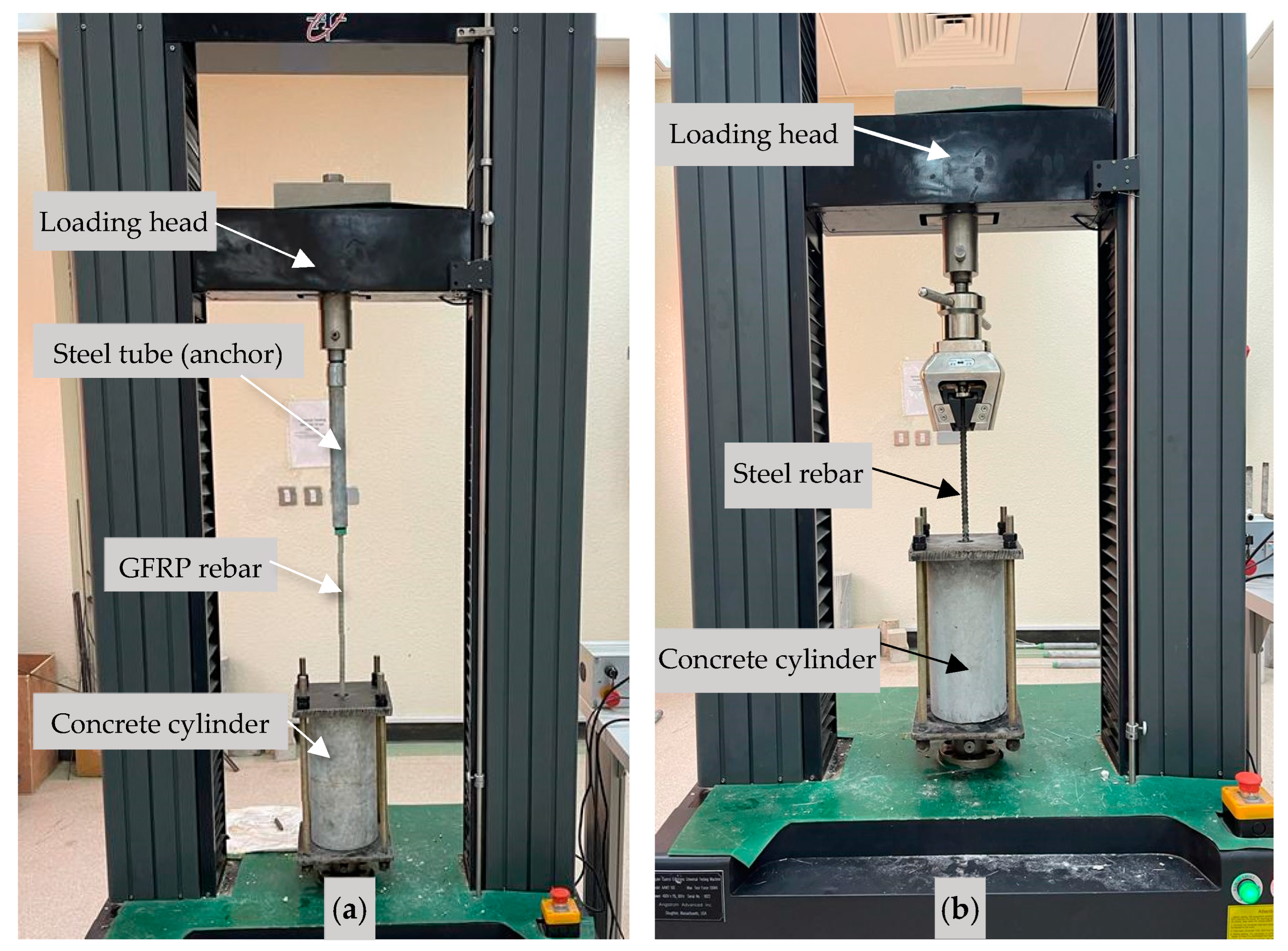
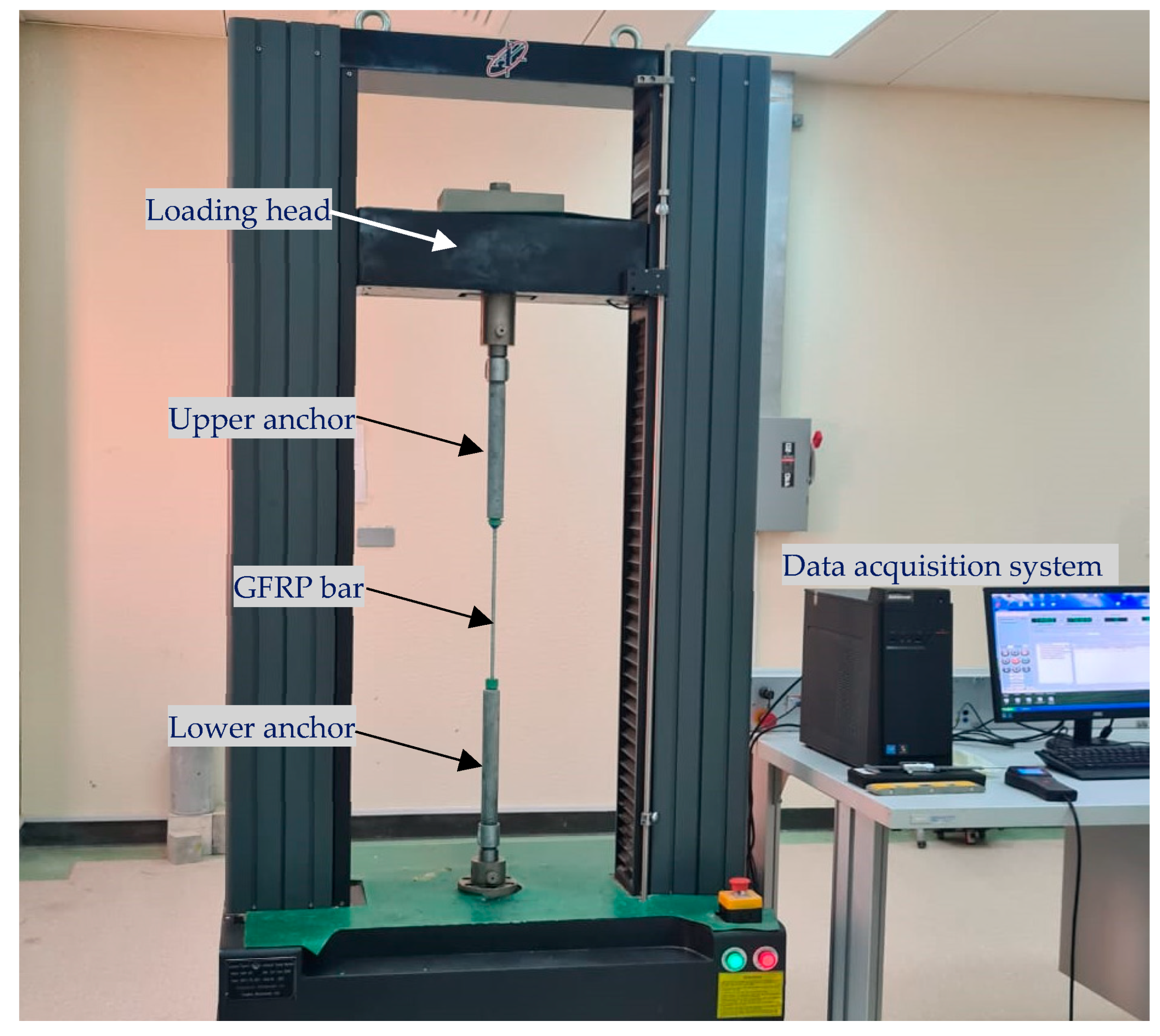
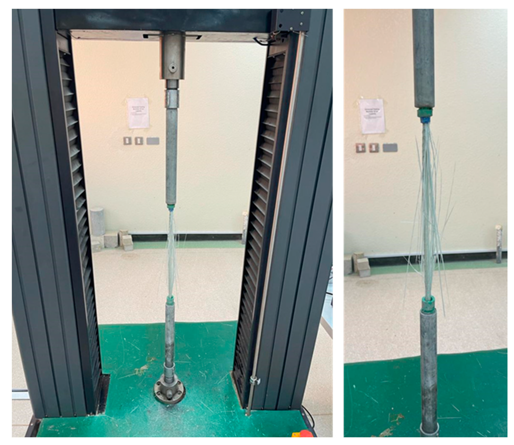
3.1. Tension Tests of Reinforcing Bars

Steel and GFRP reinforcing bar specimens were prepared for tensile testing according to ASTM A615 [8] and ASTM D7957 [31], respectively. Three steel bar specimens of nominal diameter of 12.7 mm were cut to a length of 250 ± 1 mm. GFRP bar specimens of nominal diameters of 8 mm, 10 mm, and 12.7 mm were each cut to a length of 1000 ± 1 mm. As per ASTM D7205 [58], each GFRP specimen bar was anchored to steel tubing of slightly larger diameter of 33.5 mm and a length of 330 mm at both ends to fix the specimen to the testing machine. The space between the bar and the steel tubing was filled with bonding material consisting of grout (SikaGrout-114 SA). The steel tubing was capped with polyvinyl chloride (PVC) plugs attached to threaded steel bushings that can be fastened to the testing machine. GFRP bars were acquired from Mateenbar [59]. The steel and GFRP bar specimens were tested using a universal testing machine with a 100 kN capacity with standard wedge action grips for the steel specimens and with direct fasteners for the GFRP specimens, as shown in Figure 1. Tests were conducted under displacement control conditions, applying an incremental displacement at a rate of 4 mm/min, as recommended by existing literature and standards, to induce axial tensile force [56].

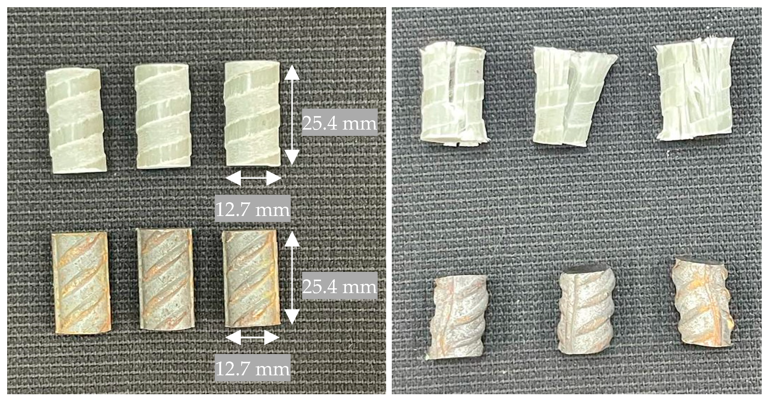
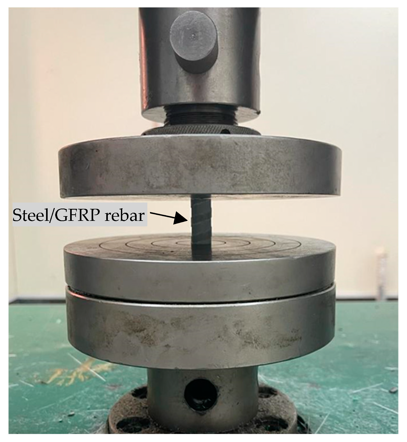
3.2. Compression Tests of Reinforcing Bars

Steel and GFRP reinforcing bar specimens were prepared for compressive testing according to ASTM E9 [60] and ASTM D695 [61], respectively. Three steel bar specimens with nominal diameters of 12.7 mm were cut to lengths of 25.4 ± 1 mm. Three GFRP bar specimens with nominal diameters of 12.7 mm were also cut to lengths of 25.4 ± 1 mm. The steel and GFRP bar specimens were tested using a universal testing machine with a 100 kN capacity with standard compression platens as shown in Figure 2. Tests were conducted under displacement control conditions, applying an incremental displacement at a rate of 1.3 ± 0.3 mm/s causing axial compressive force. The measured compressive strength of GFRP bars is intended to support the feasibility of applying GFRP bars in compression members.

3.3. Compression and Splitting Tensile Tests of Concrete Cylinders

The concrete used in casting all the test specimens in the study was of the same concrete patch. The study targets an average 28-day concrete compressive strength of 25 MPa. Details on the concrete mix portions and materials used are shown in Table 2. Concrete cylinders 150 mm in diameter and 300 mm in height were cast to obtain the compressive and splitting tensile strength of the concrete, as per ASTM C39 [62] and ASTM C496 [63], respectively. The concrete specimens were tested using a concrete compression testing machine of 3000 kN capacity with standard compression plates. Tests were conducted under force control conditions, applying an incremental force at a rate of 0.25 ± 0.05 MPa/s causing axial compressive force. In addition, the tests were conducted after 7, 14, and 28 days.

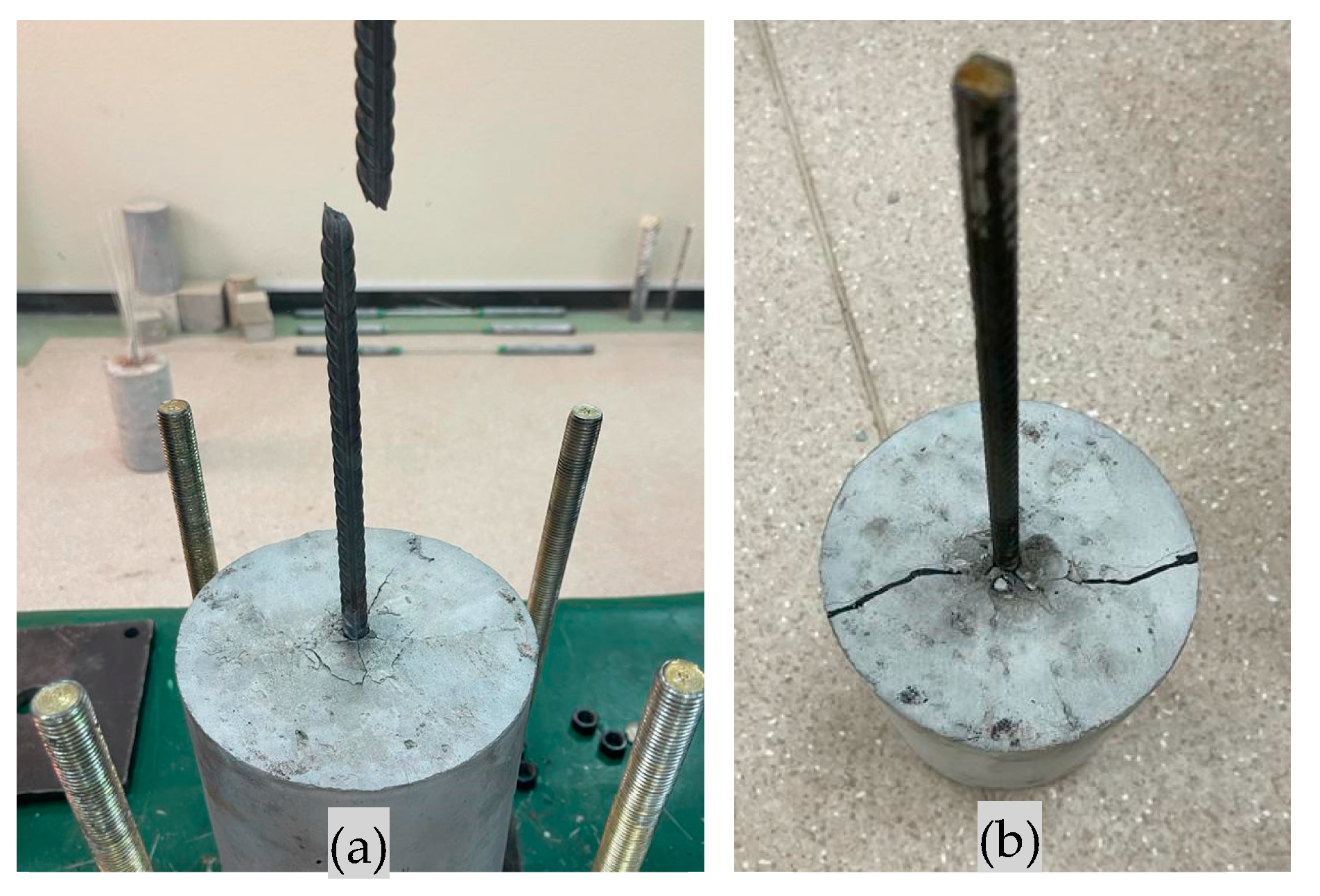
3.4. Bond Behavior Tests of Reinforcing Bars

Steel and GFRP reinforcing bar specimens were fabricated for pull-out testing according to ASTM C234 [64] and ASTM D7913 [65], respectively. Four steel and six GFRP bar specimens each with nominal diameters of 10 mm and 12.7 mm were cut to lengths of 600 and 1000 ± 1 mm, respectively. Two of the GFRP bars were sand coated and acquired from the Industrial Control Solutions Company (ICSC) [66]. The bars were partially embedded at the center of concrete cylinder molds of 150 mm in diameter and 300 mm in height containing fresh concrete. The embedment length for both steel and GFRP bars was 300 ± 1 mm. A custom-built centering device was fabricated and attached to the cylindrical concrete molds to guide steel and GFRP bars to the center of the mold during the casting of the concrete and also control the embedment depth of the bar. The steel and GFRP bars extended outside the concrete cylinders for lengths of 320 and 600 mm, receptively. Each GFRP specimen bar was anchored to steel tubing using a similar technique to that used for specimens prepared for tensile testing.
Steel and GFRP pull-out specimens were tested using a universal testing machine of 100 kN capacity. The concrete part of specimen was fixed in a custom-made rigid apparatus that was securely fixed to the bottom platen of the testing machine, so that the concrete cylinder was fixed. The extended bar of the specimen was attached to the upper moving part of the testing machine with direct fasteners for the GFRP specimens as shown in Figure 3a and with standard wedge action grips for the steel specimens as shown in Figure 3b. The test was conducted by only applying tensile force on the bar under displacement control conditions, applying incremental displacement at a rate of 2 mm/min, causing axial tensile force. The loading was applied until specimen failure by either yielding or rupture of the reinforcing bars or by the bar slipping.

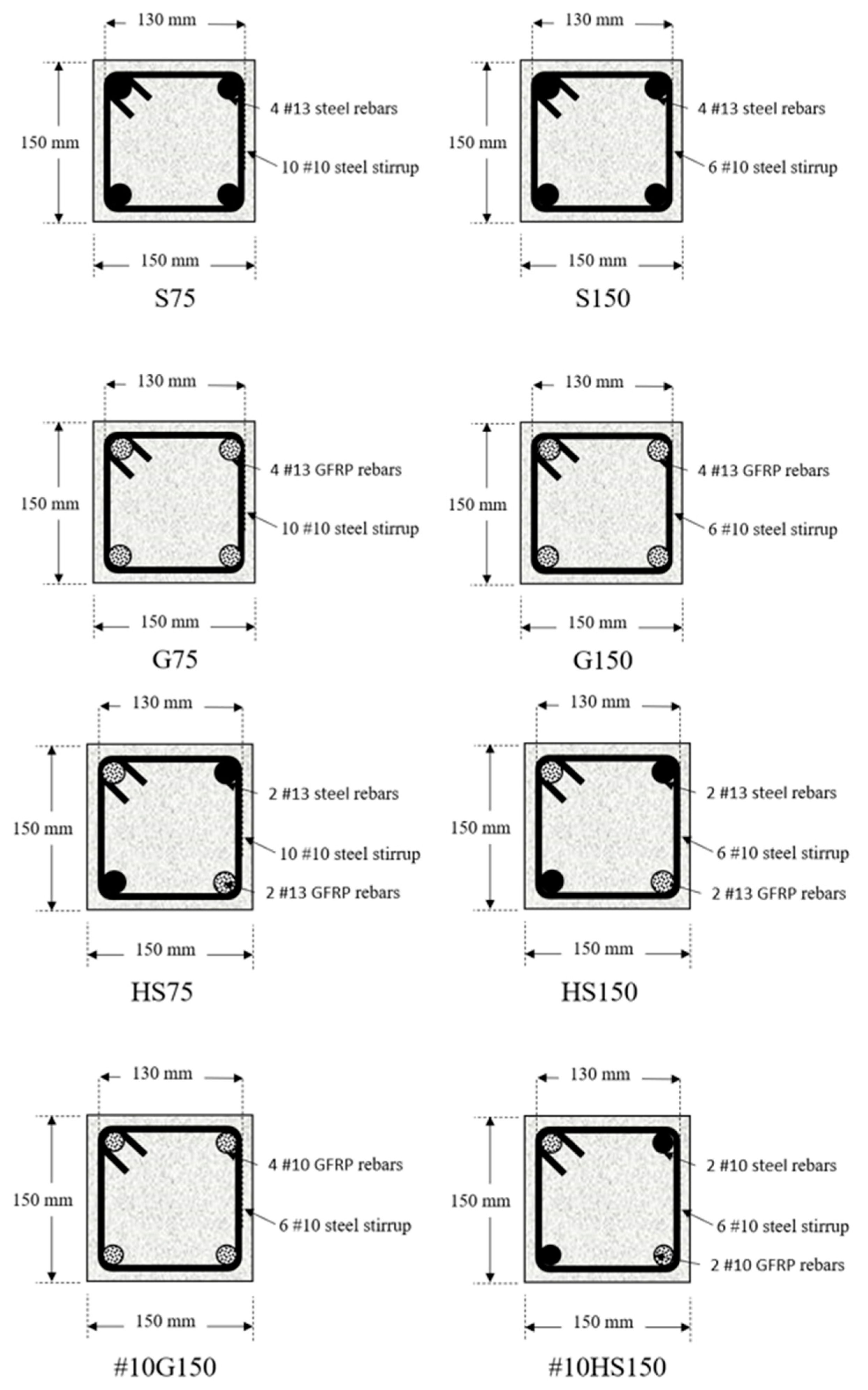
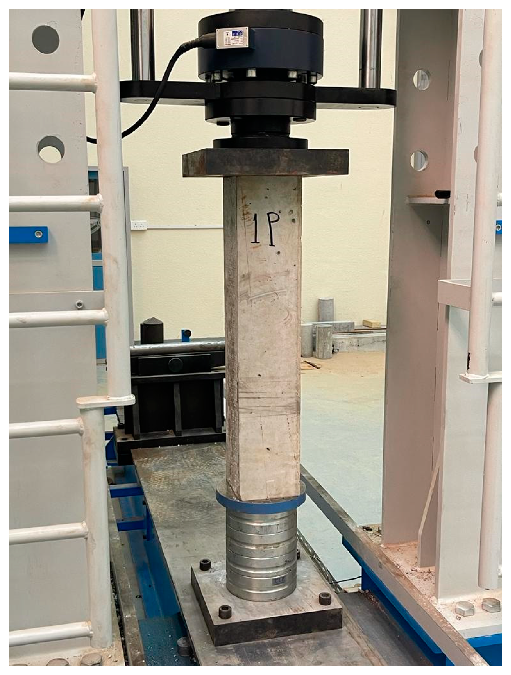
3.5. Structural Testing of Reinforced Concrete Columns

This subsection presents experimental tests on nine reinforced concrete columns to investigate the axial compressive behavior. One of the main objectives of this study is to evaluate the feasibility of using GFRP as a main longitudinal reinforcement in concrete columns. The experimental program consisted of testing nine concrete columns with various combinations of reinforcement configurations, tie spacings, and GFRP reinforcement sizes as listed in Table 3 and illustrated in Figure 4. All columns were 750 mm in height with a square cross-section with a 150 mm side length.
Column P1 was cast as plain concrete to measure the strength of concrete columns without reinforcement under pure compression. Columns S75 and S150 were fabricated with typical steel reinforcement and different tie spacings of 75 mm and 150 mm. Columns G75 and G150 were fabricated with reinforcement of 4 GFRP bars of size 13 mm with 2 ties spacings of 75 mm and 150 mm. Columns HS75 and HS150 were fabricated with hybrid reinforcement of steel and GFRP, as shown in Figure 4. Columns #10G150 and #10HS150 were constructed with 10 mm bar size as the main reinforcement and with two configurations: one with four GFRP bars, and the other with a hybrid configuration of two GFRP and two steel bars. Concrete casting procedures began with conducting the slump test to determine the workability of the fresh concrete. Concrete was poured into the column molds and spread with shovels and concrete placers. A mechanical vibrator was used to vibrate the concrete and prevent any imperfections. The reinforced concrete column specimens were tested using a structural testing machine with a 1000 kN capacity with standard compression platens as shown in Figure 5. Tests were conducted under displacement control conditions, applying incremental displacement at a rate of 2 mm/min, causing axial compressive force.

4. Experimental Results and Discussion

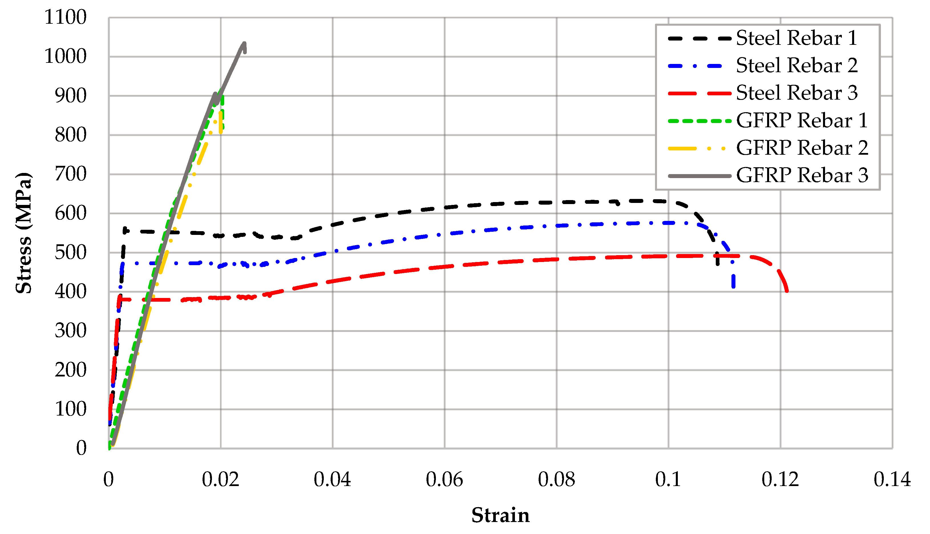
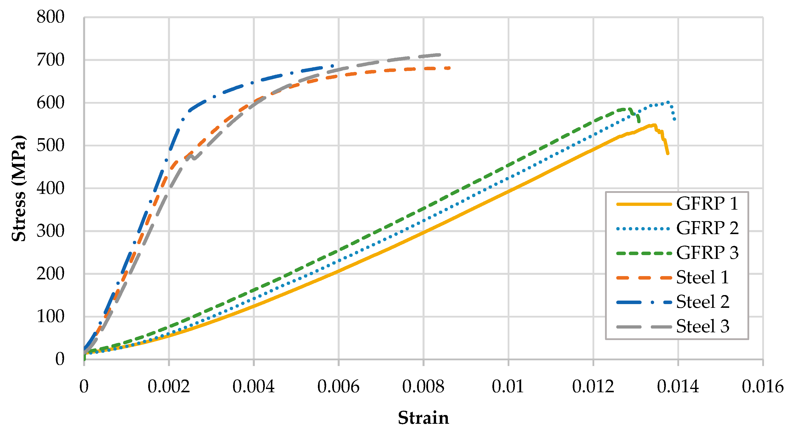
4.1. Tension Test Results of Reinforcing Bars

The yield strength of the three tested rebars is measured as expected to be higher than 420 MPa (average of results about 462 MPa) as listed in Table 4. The average ultimate tensile strength at rupture was 567 MPa. All specimens exhibited tensile behavior consistent with the requirement of ASTM A615 [8]. The typical stress–strain response of steel bars under tension reveals a progression of phases: initial linear elasticity up to the yield strength, followed by a yield plateau, then strain hardening until ultimate strength, and finally strain softening (necking) leading to failure, as shown in Figure 6.
GFRP bars under tensile loading exhibit distinct behavior compared to conventional steel bars. The stress–strain response of GFRP, as shown in Figure 6, is linear until failure. This behavior contrasts with the necking and ductile rupture observed in steel rebars. A key advantage of GFRP bars is their high tensile strength, evident in the tested specimens with an average ultimate strength of 965 MPa and a corresponding ultimate strain of 0.0201 (Table 5). All three tested GFRP specimens displayed a similar high tensile strength.
GFRP failure under tension differs significantly from steel. Steel rebars undergo necking followed by ductile rupture, whereas GFRP experiences brittle failure at ultimate load. As shown in Figure 7, the glass fibers within the polymer matrix fracture rapidly upon reaching the ultimate load. This failure mode is characterized by extensive fiber rupture and cracking of the confining polymer matrix. Despite slight variations in strain, elastic modulus, and ultimate strength, all three GFRP specimens exhibited a linear stress–strain response. GFRP demonstrated superior tensile strength compared to steel rebars, with a fully linear response preceding the brittle failure.

4.2. Compression Test Results of Reinforcing Bars

A critical aspect of this study is evaluating the behavior of GFRP bars under compressive loads. Brittleness and a linear stress–strain response up to failure raise concerns about GFRP’s compressive strength. Steel, in contrast, exhibits well-defined compression characteristics reflecting its tensile behavior: elastic until yielding, then plastic until ultimate strength, as shown in Figure 8. Due to their common applications in tension for flexural members, GFRP’s compressive strength is often overlooked. Consequently, building codes frequently disregard the contribution of GFRP bars in compression elements such as columns.
As shown in Figure 9, GFRP failure under compression is brittle, similar to its tensile behavior. This failure is characterized by a longitudinal fracture in the middle of the bar without significant rupture of the embedded glass fibers as was the case under tension. Steel rebars, however, fail in compression in a ductile manner, undergoing significant deformation or buckling before failure (Figure 9).
Table 6 summarizes the compressive strength values of GFRP and steel rebars. GFRP bars exhibited high compressive strength exceeding that of steel rebars. GFRP bars had an average compressive strength of 579 MPa, superior to steel’s average of 505 MPa by a margin of 74 MPa (or approximately 15%). GFRP bars displayed minimal variation in strength, with the lowest value of approximately 548 MPa. These results suggest that GFRP bars can significantly contribute to the compressive capacity of concrete columns.

4.3. Compression and Splitting Tensile Tests Results of Concrete Cylinders

The compressive and splitting tensile strength of concrete used in this study was evaluated using standard cylinder tests. Three cylinders were tested at 28 days after casting and curing to determine the compressive and splitting tensile strength. The concrete cylinders exhibited a compressive failure strength of approximately 25 MPa and splitting tensile strength of 3.2 MPa, as detailed in Table 7.

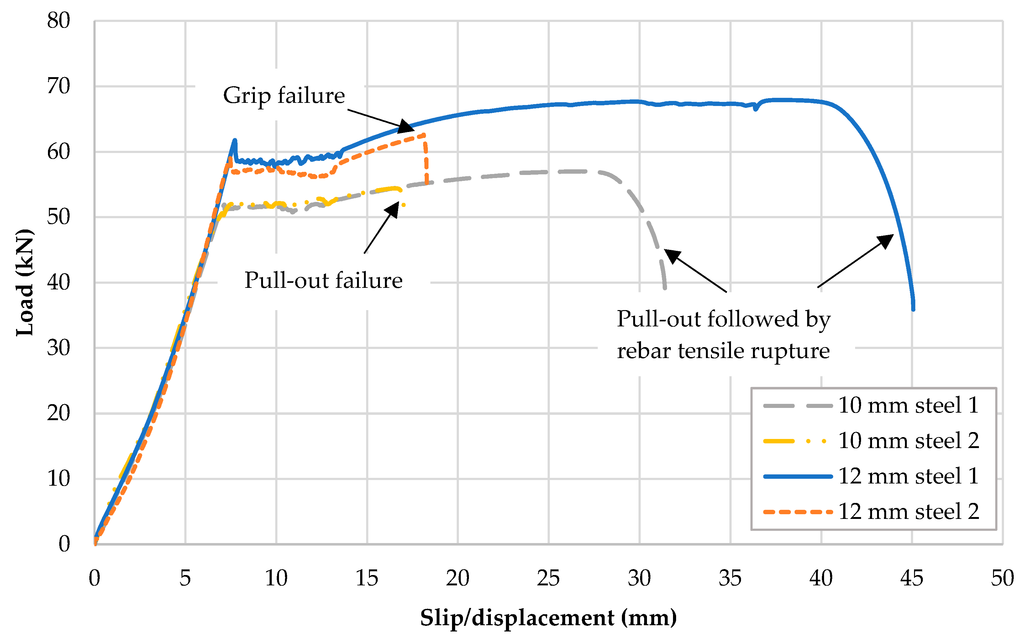
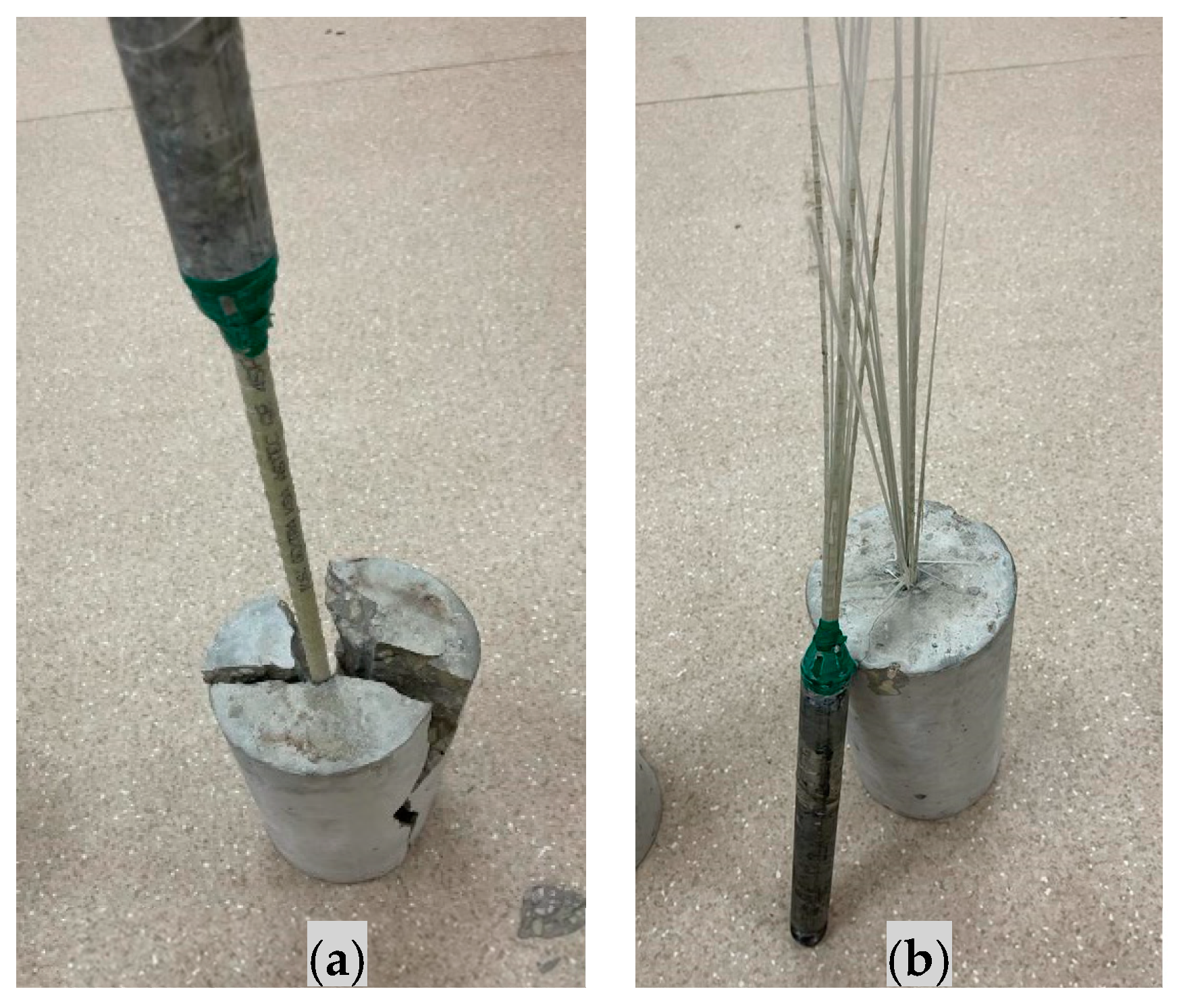
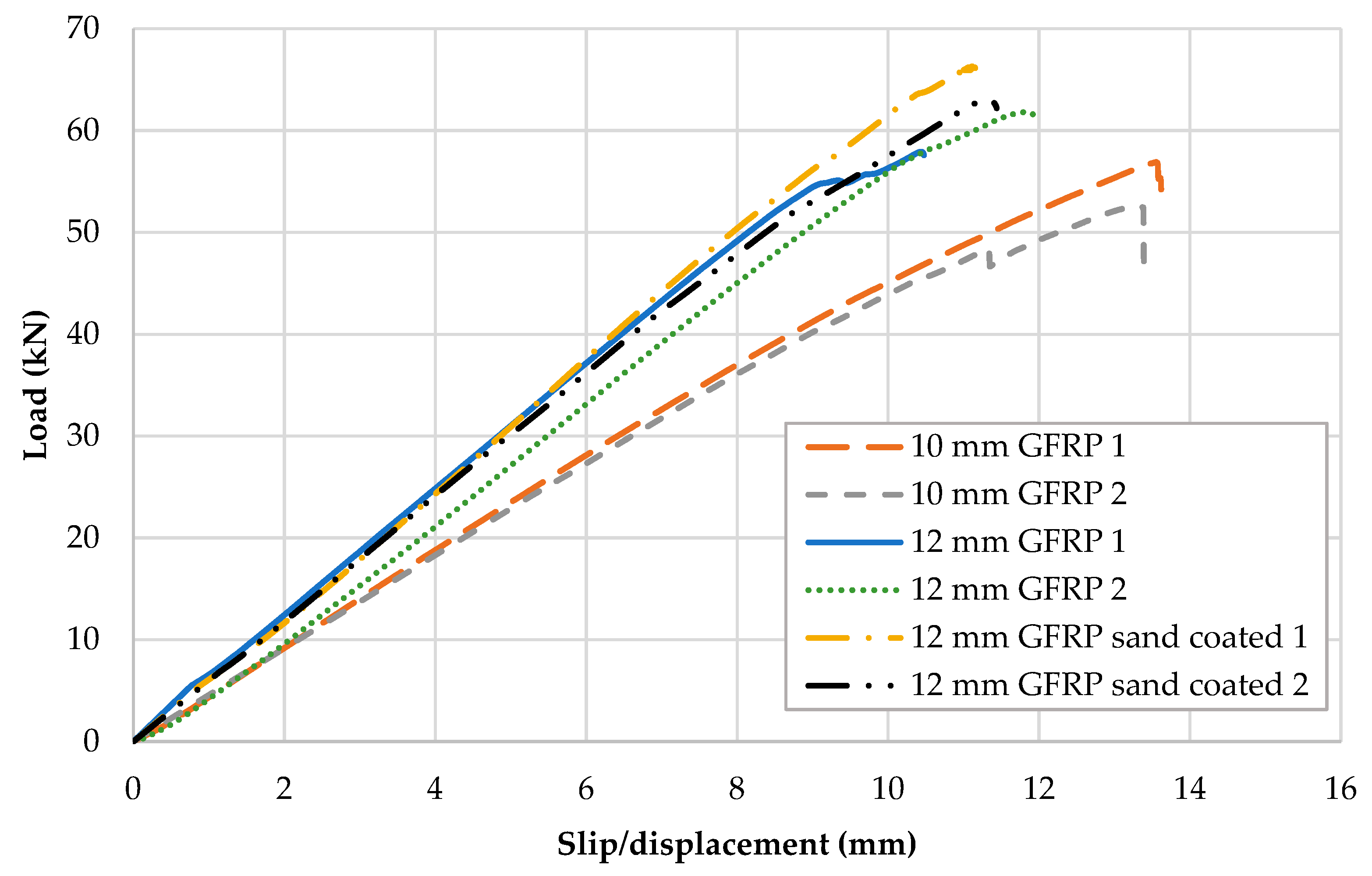
4.4. Bond Behavior Tests Results of Reinforcing Bars

Table 8 and Table 9 present the results for steel rebar and GFRP bond strength, respectively. The ultimate failure loads for steel rebars were comparable to those observed for GFRP (approximately 65 KN for a 12.7 mm diameter and 55 KN for a 10 mm diameter). A significant difference was observed in slip displacement between steel and GFRP bars. Steel rebars exhibited a much higher slip displacement compared to GFRP. The predominant failure mode for steel rebars involved pull-out followed by steel rupture, as illustrated in Figure 10. It is important to note that one specimen failed at the anchoring zone and was excluded from analysis. Figure 11 illustrates the load–slippage curves of steel bars after bond behavior tests. The curves generally exhibit an initial linear segment, signifying an elastic stage where the applied load and the slippage between the rebar and concrete are directly proportional. As the load increases, each curve reaches a peak load. This peak represents the maximum bond strength between the rebar and the concrete. Following the peak load, the curves exhibit a declining trend, indicating a decrease in load-bearing capacity with continued slippage. Some steel bars exhibit tensile rupture (10 mm steel 1 and 12 mm steel 1). Variations in peak load and the corresponding slippage values among the different curves suggest that the specific surface texture or bar diameter can significantly influence the bond behavior and steel bars.
To evaluate the bond behavior of GFRP bars in concrete, pull-out tests were conducted on specimens with different bar diameters and surface treatments. Four concrete cylinders embedded with 12.7 mm GFRP bars were tested, two with conventional ribs and two with a sand-coated surface for an enhanced bond. Furthermore, two cylinders with 10 mm GFRP bars were tested to show the effect of the bar on bond strength. For GFRP bars of size 12.7 mm, the failure mode of pull-out tests is presented in Figure 12a. For GFRP bars of size 10 mm, however, the failure occurred in the form of the glass fibers rupturing in GFRP, as shown in Figure 12b. Figure 13 illustrates the load–slippage curves of GFRP bars after bond behavior, indicating the ultimate failure load and slip displacement at failure. The ultimate loads achieved by the 12.7 mm GFRP bars indicate an acceptable bond strength, reaching values comparable to steel rebars. The sand-coated GFRP bars showed similar bond strength to the ribbed bars, as evident in the comparable ultimate loads and slip displacements (around 12.3 mm) in Table 9. This suggests that sand coating is an effective method for improving the bond strength of GFRP bars.

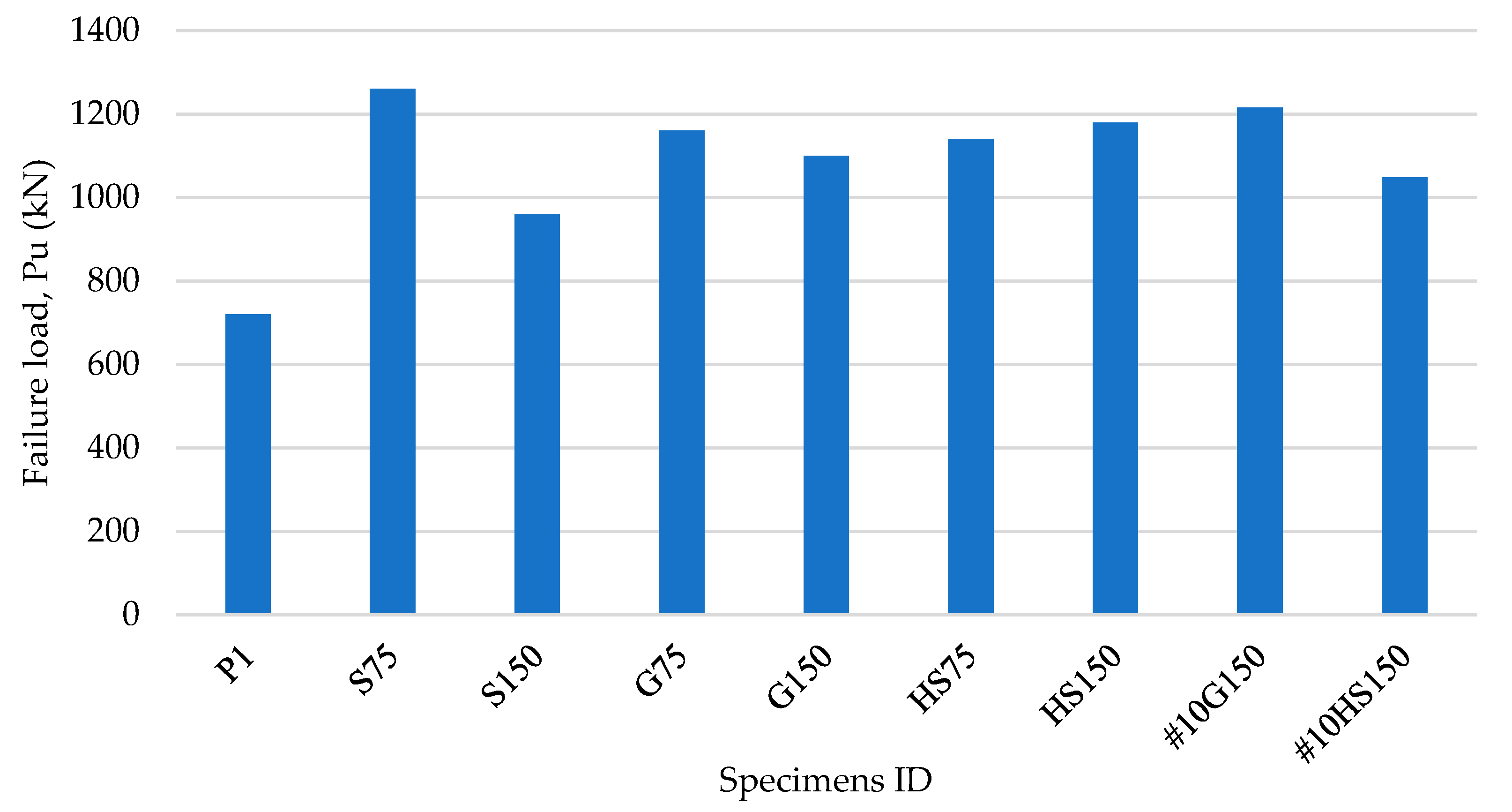
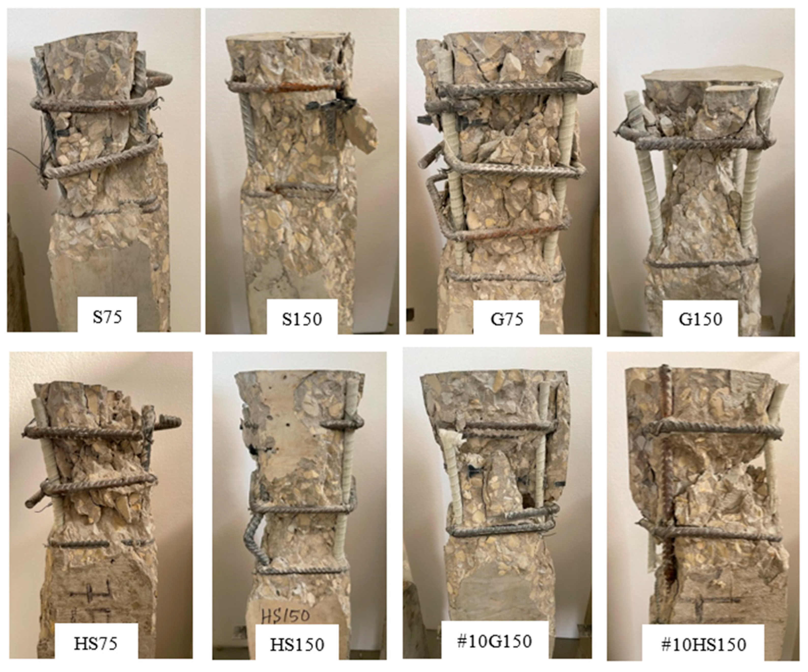
4.5. Compression Tests Results of Concrete Columns

The results of compression tests on concrete columns reinforced with GFRP bars are summarized in Table 10 and Figure 14. The observed failure modes are illustrated in Figure 15. All tested columns exhibited good performance under concentric compressive loading, exceeding the estimated capacities predicted by analytical expressions for both steel and GFRP reinforcing bars. Overall, GFRP-reinforced concrete columns achieved similar or even higher capacities compared to steel-reinforced columns. The tested columns are denoted as follows: P (plain concrete), S (steel rebars), G (GFRP bars), and HS (hybrid steel-GFRP), with numbers indicating tie spacing (e.g., 75 for 75 mm spacing). Column P1, cast with plain concrete, showed the expected crushing failure mode at a load of 720 KN (32 MPa).
The experimental results presented demonstrate the promising potential of GFRP bars as an alternative reinforcement material in concrete columns. GFRP-reinforced columns achieved compressive capacities comparable to steel-reinforced columns and exhibited similar failure modes dominated by concrete crushing and bar buckling as shown in Table 10. Column S75, reinforced with steel rebars and close-spaced ties (75 mm), achieved the highest compressive load (1260 KN) among all tested columns. The failure mode involved concrete crushing at the top of the column accompanied by spalling in the outer region (Figure 15). This superior performance is attributed to the enhanced confinement provided by the closely spaced ties, as evidenced by the opening of the top two ties at failure. In contrast, column S150, reinforced with steel but with wider tie spacing (150 mm), displayed a 20% reduction in capacity (960 KN). Its failure mode was also concrete crushing and spalling, but in the unconfined area of the cross-section.
To compare the performance of steel and GFRP bars, two similar columns (G75 and G150) were reinforced with GFRP and tested under identical conditions. Both columns exhibited capacities comparable to the steel-reinforced columns. Column G75 had a slightly lower capacity (1160 KN) than S75 by around 7%. Its failure mode involved a combination of inner concrete crushing, outer concrete spalling, GFRP bar crushing near the top, and rupture of transverse ties (Figure 15). The high confinement from the close-spaced ties allowed the GFRP bars to contribute significantly to the compressive strength until crushing. For Column G150, wider tie spacing had a minimal effect on capacity reduction (around 5% compared to S150). The failure mode of G150 was characterized by the crushing and spalling of most of the concrete between ties, along with GFRP bar crushing near the loading zone. The higher capacity observed in G75 suggests that closer tie spacing provided better confinement, leading to a slight increase in compressive strength and causing tie rupture at failure.
Columns HS75 and HS150 were tested with hybrid reinforcement (steel and GFRP) to further assess the contribution of GFRP to compressive capacity. Both columns displayed compressive capacities comparable to steel and GFRP-reinforced columns. However, the failure modes of the hybrid columns revealed that steel rebars are more susceptible to buckling in concrete columns compared to GFRP bars (Table 10 and Figure 15). Both hybrid columns experienced concrete crushing and tie rupture. The GFRP bars in both columns withstood the load until failure without rupture. This suggests that GFRP bars exhibit superior resistance to compressive stress in concrete columns compared to steel.
To evaluate the effect of using smaller GFRP bars (10 mm diameter) in concrete columns, two additional columns were tested: #10G150 and #10HS150. The compressive capacities of these two columns were similar to the other tested specimens, with slightly higher values observed for column #10G150. This higher capacity column exhibited a failure mode characterized by the crushing of concrete and all of the GFRP bars. Column#10HS150 displayed a lower failure load, as anticipated, and its failure mode involved buckling of both steel and GFRP bars, along with concrete and GFRP bar crushing at the top (Figure 15). Overall, 10 mm GFRP bars exhibited similar behavior in terms of compressive capacity but were more prone to buckling under compressive stresses.
Previous studies often tend to underestimate the capacity of concrete columns [41,42,43,44,45,46]. The estimated capacity of previous proposed equations and codes of practice tend to totally or partly neglect the contribution of GFRP bars, which results in a lower calculated capacity value (Table 11). While the inherent brittleness of GFRP bars remains a concern, its influence under compressive stresses appears to be minimal. This is due to the fact that failure, in both GFRP- and steel-reinforced columns, is primarily governed by concrete crushing and buckling of reinforced concrete at the ultimate load. These findings suggest that GFRP bars could be a viable option for concrete columns, particularly in applications where their corrosion resistance and other advantages outweigh the risk of brittleness under compression.

5. Conclusions

This study was intended to evaluate the feasibility of utilizing GFRP bars in concrete columns. In order to assess GFRP bars for use in concrete columns, an experimental regime was carried out. The experimental program consisted of tests conducted on GFRP at a material level and on GFRP bars embedded in concrete columns at a structural level. The following are the main conclusions that can be withdrawn from the work presented in this study:
  • Bond behavior of GFRP showed an excellent bond response as compared to steel rebars and can be assumed to have similar or superior bond properties than steel when embedded in concrete. This finding suggests that GFRP bars can effectively transfer loads between the concrete and the reinforcement, potentially leading to improved overall column performance.
  • Concrete columns reinforced with GFRP resulted in a comparable compressive capacity to those reinforced with steel rebars. In certain cases, the capacity of columns reinforced with GFRP yielded higher values than those reinforced with steel. Contrary to the current design practice, GFRP contributes significantly to the compressive capacity of concrete columns.
  • Closely spaced ties in column significantly enhanced the compressive load capacity compared to wider tie spacing, demonstrating the critical role of tie spacing in optimizing column performance. This finding is further supported by the minimal reduction in capacity (5–7%) observed in GFRP-reinforced columns with wider tie spacing compared to steel-reinforced columns. This highlights the effectiveness of GFRP bars in contributing to the compressive strength of concrete columns even with less confining tie spacing.
  • The failure modes observed in both steel and GFRP-reinforced columns were predominantly concrete crushing and bar buckling, consistent with the analytical models used for capacity prediction.
  • While the brittle behavior of GFRP bars is a concern in concrete members, it has a minimal impact on compressive strength. This is because the failure mode for both steel and GFRP-reinforced columns under compression is primarily governed by concrete crushing and bar buckling, not the brittleness of the reinforcing material.
  • While GFRP bars offer advantages like high tensile strength and corrosion resistance, they present limitations compared to steel. These include a more brittle failure mode with minimal plastic deformation, lower stiffness leading to potentially larger deflections, and the need for special design considerations in seismic regions to ensure adequate anchorage due to bond behavior. Additionally, further research is necessary to fully understand the behavior of GFRP bars under dynamic tension, particularly crucial for applications in earthquake-prone areas.

Author Contributions

Conceptualization, E.A. and M.A.; methodology, E.A., M.A. and S.M.A.; software, O.A.; validation, E.A., M.A., M.K.A. and O.A.; formal analysis, M.A.; investigation, E.A., S.M.A. and E.B.; resources, E.A., S.M.A. and A.A.; data curation, E.A., M.K.A., E.B. and A.A.; writing—original draft preparation, M.A. and M.K.A.; writing—review and editing, M.A., M.K.A. and E.A.; visualization, S.M.A. and O.A.; supervision, E.A.; project administration, M.A.; funding acquisition, E.A. All authors have read and agreed to the published version of the manuscript.

Funding

This research was funded by Research and Studies Center through the Saudi Standards, Metrology, and Quality Organization (SASO), grant number 15-4-12, and the APC was funded by the Deanship of Scientific Research, Qassim University.

Data Availability Statement

The original contributions presented in the study are included in the article, further inquiries can be directed to the corresponding author.

Acknowledgments

The authors express their sincere gratitude to the Research and Studies Center at SASO for their funding through grant number 15-4-12. The researchers would also like to thank the Deanship of Scientific Research, Qassim University, for funding the publication of this research.

Conflicts of Interest

The authors declare no conflicts of interest.

References

  1. Mallick, P.K. Fiber-Reinforced Composites; CRC Press: Boca Raton, FL, USA, 2007. [Google Scholar] [CrossRef]
  2. Wu, W.-P. Thermomechanical Properties of Fiber-Reinforced Plastic (FRP) Bars; West Virginia University: Morgantown, WV, USA, 1991. [Google Scholar]
  3. Deitz, D.H.; Harik, I.E.; Gesund, H. Physical Properties of Glass Fiber Reinforced Polymer Rebars in Compression. J. Compos. Constr. 2003, 7, 363–366. [Google Scholar] [CrossRef]
  4. Chaallal, O.; Benmokrane, B. Physical and mechanical performance of an innovative glass-fiber-reinforced plastic rod for concrete and grouted anchorages. Can. J. Civ. Eng. 1993, 20, 254–268. [Google Scholar] [CrossRef]
  5. ACI 318; Building Code Requirements for Structural Concrete. American Concrete Institute. ACI Committee: Indianapolis, IN, USA, 2014.
  6. Saudi Concrete Structures Code SBC 304-CR Code Requirements; The Saudi Building Code National Committee (SBCNC): Riyadh, Saudi Arabia, 2018.
  7. AASHTO. AASHTO LRFD Bridge Design Specifications, 8th ed.; AASHTO: Washington, DC, USA, 2017. [Google Scholar]
  8. A615/A 615M-04a; Standard Specification for Deformed and Plain Carbon Steel Bars for Concrete Reinforcement. 2012. Available online: www.astm.org (accessed on 8 April 2024).
  9. A706/A706M−13; Standard Specification for Low-Alloy Steel Deformed and Plain Bars for Concrete Reinforcement. 2013. Available online: https://doi.org/10.1520/A0706_A0706M-13 (accessed on 8 April 2024).
  10. Gomes, A.; Appleton, J. Nonlinear cyclic stress-strain relationship of reinforcing bars including buckling. Eng. Struct. 1997, 19, 822–826. [Google Scholar] [CrossRef]
  11. Dodd, L.L.; Restrepo-Posada, J.I. Model for Predicting Cyclic Behavior of Reinforcing Steel. J. Struct. Eng. 1995, 121, 433–445. [Google Scholar] [CrossRef]
  12. Djavanroodi, F.; Salman, A. Variability of Mechanical Properties and Weight for Reinforcing Bar Produced in Saudi Arabia. IOP Conf. Ser. Mater. Sci. Eng. Inst. Phys. Publ. 2017, 230, 012002. [Google Scholar] [CrossRef]
  13. Paulay, T.; Priestley, M.J.N. Seismic Design of Reinforced Concrete and Masonry Buildings; Wiley & Sons: New York, NY, USA, 1992. [Google Scholar]
  14. Priestley, M.J.N.; Calvi, G.M.; Kowalsky, M.J. Displacement-Based Seismic Design of Structures; IUSS Press: Pavia, Italy, 2007. [Google Scholar]
  15. AlAjarmeh, O.S.; Manalo, A.C.; Benmokrane, B.; Karunasena, W.; Mendis, P. Axial performance of hollow concrete columns reinforced with GFRP composite bars with different reinforcement ratios. Compos. Struct. 2019, 213, 153–164. [Google Scholar] [CrossRef]
  16. El-Nemr, A.; Ahmed, E.A.; Benmokrane, B. Flexural Behavior and Serviceability of Normal- and High-Strength Concrete Beams Reinforced with Glass Fiber-Reinforced Polymer Bars. ACI Struct. J. 2013, 110, 1077–1088. [Google Scholar] [CrossRef]
  17. Maranan, G.B.; Manalo, A.C.; Benmokrane, B.; Karunasena, W.; Mendis, P. Behavior of concentrically loaded geopolymer-concrete circular columns reinforced longitudinally and transversely with GFRP bars. Eng. Struct. 2016, 117, 422–436. [Google Scholar] [CrossRef]
  18. Maranan, G.B.; Manalo, A.C.; Benmokrane, B.; Karunasena, W.; Mendis, P.; Nguyen, T.Q. Shear behaviour of geopolymer-concrete beams transversely reinforced with continuous rectangular GFRP composite spirals. Compos. Struct. 2018, 187, 454–465. [Google Scholar] [CrossRef]
  19. BBenmokrane; Nazair, C.; Seynave, X.; Manalo, A. Comparison between ASTM D7205 and CSA S806 Tensile-Testing Methods for Glass Fiber–Reinforced Polymer Bars. J. Compos. Constr. 2017, 21, 04017038. [Google Scholar] [CrossRef]
  20. Benmokrane, B.; Manalo, A.; Bouhet, J.-C.; Mohamed, K.; Robert, M. Effects of Diameter on the Durability of Glass Fiber–Reinforced Polymer Bars Conditioned in Alkaline Solution. J. Compos. Constr. 2017, 21, 04017040. [Google Scholar] [CrossRef]
  21. Benmokrane, B.; Ali, A.H.; Mohamed, H.M.; ElSafty, A.; Manalo, A. Laboratory assessment and durability performance of vinyl-ester, polyester, and epoxy glass-FRP bars for concrete structures. Compos. B Eng. 2017, 114, 163–174. [Google Scholar] [CrossRef]
  22. Nazair, C.; Benmokrane, B.; Loranger, M.-A.; Robert, M.; Manalo, A. A comparative study of the thermophysical and mechanical properties of the glass fiber reinforced polymer bars with different cure ratios. J. Compos. Mater. 2018, 52, 4105–4116. [Google Scholar] [CrossRef]
  23. Maranan, G.; Manalo, A.; Karunasena, K.; Benmokrane, B. Bond Stress-Slip Behavior: Case of GFRP Bars in Geopolymer Concrete. J. Mater. Civ. Eng. 2015, 27, 04014116. [Google Scholar] [CrossRef]
  24. Maranan, G.B.; Manalo, A.C.; Karunasena, W.; Benmokrane, B. Pullout behaviour of GFRP bars with anchor head in geopolymer concrete. Compos. Struct. 2015, 132, 1113–1121. [Google Scholar] [CrossRef]
  25. Benmokrane, B.; Nazair, C.; Loranger, M.-A.; Manalo, A. Field Durability Study of Vinyl-Ester–Based GFRP Rebars in Concrete Bridge Barriers. J. Bridge Eng. 2018, 23, 04018094. [Google Scholar] [CrossRef]
  26. Wijayawardane, I.S.K.; Mutsuyoshi, H.; Nguyen, H.; Manalo, A. Flexural behaviour of glass fibre-reinforced polymer and ultra-high-strength fibre-reinforced concrete composite beams subjected to elevated temperature. Adv. Struct. Eng. 2017, 20, 1357–1374. [Google Scholar] [CrossRef]
  27. Davalos, J.F.; Chen, Y.; Ray, I. Long-term durability prediction models for GFRP bars in concrete environment. J. Compos. Mater. 2012, 46, 1899–1914. [Google Scholar] [CrossRef]
  28. Robert, M.; Benmokrane, B. Behavior of GFRP Reinforcing Bars Subjected to Extreme Temperatures. J. Compos. Constr. 2010, 14, 353–360. [Google Scholar] [CrossRef]
  29. Brahim, B.; Mohamed, H.M.; Allan, M.; Patrice, C. Evaluation of Physical and Durability Characteristics of New Headed Glass Fiber–Reinforced Polymer Bars for Concrete Structures. J. Compos. Constr. 2017, 21, 04016081. [Google Scholar] [CrossRef]
  30. CSA S807:19; Specification for Fibre-Reinforced Polymers. CSA Group: Toronto, ON, Canada, 2019.
  31. D7957/D7957M; 17 Standard Specification for Solid Round Glass Fiber Reinforced Polymer Bars for Concrete Reinforcement 1. ASTM: Conshohocken, PA, USA, 2017. [CrossRef]
  32. Taerwe, L. Non-Metallic (FRP) Reinforcement for Concrete Structures; CRC Press: Boca Raton, FL, USA, 2004. [Google Scholar] [CrossRef]
  33. Paramanantham, N.S. Investigation of the Behavior of Concrete Columns Reinforced with Fiber Reinforced Plastic Rebars. Master’s Thesis, Lamar University, Beaumont, TX, USA, 1993. [Google Scholar]
  34. Alsayed, S.H.; Al-Salloum, Y.A.; Almusallam, T.H.; Amjad, M.A. Concrete Columns Reinforced by Glass Fiber Reinforced Polymer Rods. In SP-188: 4th Intl Symposium—Fiber Reinforced Polymer Reinforcement for Reinforced Concrete Structures; American Concrete Institute: Indianapolis, IN, USA, 1999. [Google Scholar] [CrossRef]
  35. Lotfy, E. Behavior of reinforced concrete short columns with fiber reinforced polymers bars. Int. J. Civ. Struct. Eng. 2010, 1, 545–557. [Google Scholar]
  36. Tobbi, H.; Farghaly, A.S.; Benmokrane, B. Concrete Columns Reinforced Longitudinally and Transversally with Glass Fiber-Reinforced Polymer Bars. ACI Struct. J. 2012, 109, 551–558. [Google Scholar] [CrossRef]
  37. American Association of State Highway and Transportation Officials. Standard Specifications for Highway Bridges; American Association of State Highway and Transportation Officials: Washington, DC, USA, 2002. [Google Scholar]
  38. ACI Committee 440. Guide for the Design and Construction of Structural Concrete Reinforced with Fiber-Reinforced Polymer FRP Bars; American Concrete Institute: Indianapolis, IN, USA, 2015. [Google Scholar]
  39. Commentary on CAN/CSA-S6-06. Canadian Highway Bridge Design Code. 2006. Available online: www.ShopCSA.ca (accessed on 8 April 2024).
  40. Isleem, H.F.; Tayeh, B.A.; Alaloul, W.S.; Musarat, M.A.; Raza, A. Artificial Neural Network (ANN) and Finite Element (FEM) Models for GFRP-Reinforced Concrete Columns under Axial Compression. Materials 2021, 14, 7172. [Google Scholar] [CrossRef] [PubMed]
  41. Karabinis, A.I.; Rousakis, T.C. Concrete confined by FRP material: A plasticity approach. Eng. Struct. 2002, 7, 923–932. Available online: https://www.infona.pl//resource/bwmeta1.element.elsevier-15d1e761-db73-3f01-b5d2-f85481f0f5a6 (accessed on 22 January 2023). [CrossRef]
  42. Xie, J.; Huang, L.; Guo, Y.; Li, Z.; Fang, C.; Li, L.; Wang, J. Experimental study on the compressive and flexural behaviour of recycled aggregate concrete modified with silica fume and fibres. Constr. Build. Mater. 2018, 178, 612–623. [Google Scholar] [CrossRef]
  43. Afifi, M.Z.; Mohamed, H.M.; Benmokrane, B. Axial Capacity of Circular Concrete Columns Reinforced with GFRP Bars and Spirals. J. Compos. Constr. 2014, 18, 04013017. [Google Scholar] [CrossRef]
  44. Mohamed, H.M.; Afifi, M.Z.; Benmokrane, B. Performance Evaluation of Concrete Columns Reinforced Longitudinally with FRP Bars and Confined with FRP Hoops and Spirals under Axial Load. J. Bridge Eng. 2014, 19, 04014020. [Google Scholar] [CrossRef]
  45. Tobbi, H.; Farghaly, A.S.; Benmokrane, B. Behavior of Concentrically Loaded Fiber-Reinforced Polymer Reinforced Concrete Columns with Varying Reinforcement Types and Ratios. ACI Struct. J. 2014, 111, 375–386. [Google Scholar] [CrossRef]
  46. Khan, Q.S.; Sheikh, M.N.; Hadi, M.N.S. Axial-Flexural Interactions of GFRP-CFFT Columns with and without Reinforcing GFRP Bars. J. Compos. Constr. 2017, 21, 04016109. [Google Scholar] [CrossRef]
  47. Baig, M.; Zain-Ul-Abideen; Munir, Q.; Ahmad, B. Bond Performance of Zinc Galvanized Rebars in Reinforced Concrete and their Effectiveness in Corrosion Prevention. Int. Res. J. Mod. Eng. Technol. Sci. 2022, 4. [Google Scholar] [CrossRef]
  48. Sólyom, S.; Balázs, G. Bond Strength of FRP Rebars. Concr. Struct. 2015, 16, 62–68. [Google Scholar]
  49. Fawaz, G.; Murcia-Delso, J. Bond behavior of iron-based shape memory alloy reinforcing bars embedded in concrete. Mater. Struct. 2020, 53, 114. [Google Scholar] [CrossRef]
  50. Amin, M.; Althoey, F.; Khan, K.; Faraz, M.; Qadir, M.; Alabdullah, A.; Ajwad, A.; Sarker, P.; Iqbal, M. Investigating the Bond Strength of FRP Rebars in Concrete under High Temperature Using Gene-Expression Programming Model. Polymers 2022, 14, 2992. [Google Scholar] [CrossRef] [PubMed]
  51. Yuan, Y.; Li, M.; Alquraishi, A.S.S.; Sun, H. Experimental Study on the Novel Interface Bond Behavior between Fiber-Reinforced Concrete and Common Concrete through 3D-DIC. Adv. Mater. Sci. Eng. 2021, 2021, 1–21. [Google Scholar] [CrossRef]
  52. Vembu, P.R.S.; Ammasi, A.K. A Comprehensive Review on the Factors Affecting Bond Strength in Concrete. Buildings 2023, 13, 577. [Google Scholar] [CrossRef]
  53. Sólyom, S.; Balázs, G.L.; Sólyom -György, S.; Balázs, L. Bond Strength of FRP Rebars. 2015. Available online: https://www.researchgate.net/publication/308688068 (accessed on 8 April 2024).
  54. Wu, C.; Bai, Y.; Kwon, S. Improved bond behavior between GFRP rebar and concrete using calcium sulfoaluminate. Constr. Build. Mater. 2016, 113, 897–904. [Google Scholar] [CrossRef]
  55. Cosenza, E.; Manfredi, G.; Realfonzo, R. Development length of FRP straight rebars. Compos. B Eng. 2002, 33, 493–504. [Google Scholar] [CrossRef]
  56. Golafshani, E.M.; Rahai, A.; Sebt, M.H. Bond behavior of steel and GFRP bars in self-compacting concrete. Constr. Build. Mater. 2014, 61, 230–240. [Google Scholar] [CrossRef]
  57. Okelo, R.; Yuan, R.L. Bond Strength of Fiber Reinforced Polymer Rebars in Normal Strength Concrete. J. Compos. Constr. 2005, 9, 203–213. [Google Scholar] [CrossRef]
  58. ASTM D7205/D7205M-06; Standard Test Method for Tensile Properties of Fiber Reinforced Polymer Matrix Composite Bars 1. ASTM International: West Conshohocken, PN, USA, 2016. [CrossRef]
  59. Mateenbar Limited, Mateenbar. 2023. Available online: https://mateenbar.com/products/mateenbar/ (accessed on 8 April 2024).
  60. ASTM E9-09; Standard Test Methods of Compression Testing of Metallic Materials at Room Temperature. ASTM International: West Conshohocken, PN, USA, 2009. [CrossRef]
  61. ASTM D695-15; Standard Test Method for Compressive Properties of Rigid Plastics. ASTM International: West Conshohocken, PN, USA, 2015. [CrossRef]
  62. ASTM C39; Standard Test Method for Compressive Strength of Cylindrical Concrete Specimens. ASTM International: West Conshohocken, PN, USA, 2021. [CrossRef]
  63. ASTM C496; Standard Test Method for Splitting Tensile Strength of Cylindrical Concrete Specimens. ASTM International: West Conshohocken, PN, USA, 2017. [CrossRef]
  64. ASTM C234; Standard Test Method for Bond Strength of Concrete Developed with Reinforcing Steel. ASTM International: West Conshohocken, PN, USA, 1991.
  65. ASTM D7913/D7913M-14; Standard Test Method for Bond Strength of Fiber-Reinforced Polymer Matrix Composite Bars to Concrete by Pullout Testing. ASTM International: West Conshohocken, PN, USA, 2020. [CrossRef]
  66. Industrial Control Solutions Company (ICSC). Industrial Control Solutions Company (ICSC) a Manufacturer of Glass Fiber Reinforce Polymer (GFRP) Rebars in Saudi Arabia; Industrial Control Solutions Company (ICSC): Dammam, Saudi Arabia, 2023. [Google Scholar]
Figure 1. Tension test setup for GFRP bar specimens.
Buildings 14 01071 g001
Figure 2. Compression test setup for steel and GFRP bar specimens.
Buildings 14 01071 g002
Figure 3. Pull-out test setup of concrete cylinder with partially embedded rebar. (a) GFRP rebar; (b) steel rebar.
Buildings 14 01071 g003
Figure 4. Reinforcement configuration of concrete column specimens.
Buildings 14 01071 g004
Figure 5. Axial compression test setup of reinforced concrete column specimens.
Buildings 14 01071 g005
Figure 6. Stress–strain behavior of steel and GFRP bars after tensile test.
Buildings 14 01071 g006
Figure 7. Tensile test of GFRP bar after failure.
Buildings 14 01071 g007
Figure 8. Stress–strain behavior of steel and GFRP bars after compressive test.
Buildings 14 01071 g008
Figure 9. GFRP and steel specimens before and after compressive test.
Buildings 14 01071 g009
Figure 10. Failure modes of specimens after pull-out test of concrete cylinder with partially embedded steel rebar; (a) pull-out followed by rebar tensile rupture; (b) pull-out/splitting.
Buildings 14 01071 g010
Figure 11. Load–slippage curves of steel bars after bond behavior tests.
Buildings 14 01071 g011
Figure 12. Specimens after pull-out test of concrete cylinder with partially embedded GFRP rebar; (a) #12 GFRP bar; (b) #10 GFRP bar.
Buildings 14 01071 g012
Figure 13. Load–slippage curves of GFRP bars after bond behavior tests.
Buildings 14 01071 g013
Figure 14. Failure load comparison of the tested specimens of reinforced concrete columns with GFRP and steel rebars.
Buildings 14 01071 g014
Figure 15. Specimens of reinforced concrete columns with GFRP and steel rebars after compression test.
Buildings 14 01071 g015
Table 1. Summary of design equations available in the literature for GFRP RC columns.
Researcher/StanderProposed Models
CSA S806-12 [41] P n = α 1 f c ( A g A F R P )
α 1 = 0.85 0.0015 f c 0.67
CSA S806-02 [42] P n = 0.85 f c ( A g A F R P )
Afifi et al. [43] P n = 0.85 f c ( A g A F R P ) + 0.35 f F R P A F R P
Mohamed et al. [44] P n = 0.85 f c ( A g A F R P ) + 0.002 E F R P A F R P
Tobbi et al. [45] P n = 0.85 f c ( A g A F R P ) + 0.003 E F R P A F R P
Khan et al. [46] P n = 0.85 f c ( A g A F R P ) + 0.61 f F R P A F R P
Note: A F R P = area of FRP longitudinal reinforcement; A g = gross area of column section; E F R P = tensile Young’s modulus of the FRP bars; f c = compressive strength of unconfined concrete; f F R P = FRP tensile strength; P n = nominal capacity corresponding to first peak load.
Table 2. Concrete mix design.
Item TypeItem DescriptionAmount (kg/m3)Quantity (%)Specific Gravity
CementCement Type I (OPC)32013.533.15
WaterWater (Raw)1526.421.00
Coarse Aggregate20 mm66027.902.60
Coarse Aggregate10 mm44018.602.61
Fine AggregateDune red sand79033.392.60
AdmixtureMaster Pozzolith 33320.101.22
AdmixtureMaster Ease 37601.80.081.09
Table 3. Summary of concrete column reinforced with steel and GFRP bars.
Specimen IDLongitudinal Reinforcement Size, TypeTransverse Reinforcement Spacing, mmTransverse Reinforcement Size, Type
P1------
S754 #13, Steel7510 #10, Steel
S1504 #13, Steel1506 #10, Steel
G754 #13, GFRP7510 #10, Steel
G1504 #13, GFRP1506 #10, Steel
HS752 #13, Steel
2 #13, GFRP
7510 #10, Steel
HS1502 #13, Steel
2 #13, GFRP
1506 #10, Steel
#10G1504 #10, GFRP1506 #10, Steel
#10HS1502 #10, Steel
2 #10, GFRP
1506 #10, Steel
Note: The columns are annotated with letters P (plain concrete), S (steel rebars), G (GFRP bars), and HS (hybrid rebars of steel and GFRP).
Table 4. Measured tensile strength properties of steel bars.
Sample #Yielding Load (kN)Yielding Stress (MPa)Tensile Load (kN)Tensile Stress (MPa)
Steel 168.654280.1632
Steel 259.346873.0576
Steel 347.737762.3492
Average58.546271.8567
Table 5. Measured stress–strain values of GFRP bars.
GFRP SampleLoad (kN)Tensile Stress (MPa)Failure Strain
GFRP 146.09160.0189
GFRP 243.19440.0187
GFRP 352.010340.0227
Average47.19650.0201
Table 6. Measured compressive strength of GFRP and steel rebars.
SpecimensLoad (kN)Compressive Stress (MPa)
GFRP 169.4548
GFRP 276.1601
GFRP 374.4587
Average73.3579
Steel 159.1467 (Yeilding)
Steel 273.3578 (Yeilding)
Steel 359.7471 (Yeilding)
Average64.0505 (Yeilding)
Table 7. Measured compressive and splitting tensile strength values of concrete cylinders.
SamplesCompressive Stress (MPa)Splitting Tensile Strength (MPa)
Concrete cylinder 124.52.9
Concrete cylinder 224.43.2
Concrete cylinder 326.63.5
Average25.23.2
Table 8. Results of pull-out bond strength tests on steel rebars.
Rebar SpecimensUltimate Load, kNUltimate Slip, mmFailure Mode
10 mm steel 156.931Pull-out followed by rebar tensile rupture
10 mm steel 254.517Pull-out
12.7 mm steel 167.945Pull-out followed by rebar tensile rupture
12.7 mm steel 262.618Pull-out followed by grip failure
Table 9. Results of pull-out bond strength tests on GFRP bars.
Bar SpecimensUltimate Load, kNUltimate Slip, mmFailure Mode
12.7 mm GFRP 157.9212Concrete cylinder failure and splitting into three pieces
12.7 mm GFRP 261.8412
12.7 mm GFRP sand coated 166.3412.5
12.7 mm GFRP sand coated 262.9513
Average62.2612.375
10 mm GFRP 156.913.62GFRP tensile rupture
10 mm GFRP 252.415.79
Average54.6514.7
Table 10. Results of compression tests on GFRP- and steel-reinforced concrete columns.
Specimen IDFailure Load, Pu (kN)Failure Mode
P17201/Compressive concrete crushing (CC)/concrete spalling.
S751260
S150960
G7511601/Compressive concrete crushing (CC)/concrete spalling.
2/Crushing of GFRP longitudinal bar near loading location.
3/Transverse reinforcement tie rupture.
G15011001/Compressive concrete crushing (CC)/concrete spalling.
2/Crushing of GFRP longitudinal bar near loading location.
HS7511401/Compressive concrete crushing (CC)/concrete spalling.
2/Transverse reinforcement tie rupture.
HS15011801/Compressive concrete crushing (CC)/concrete spalling.
2/Buckling of steel longitudinal bar.
3/Transverse reinforcement tie rupture.
#10G15012151/Compressive concrete crushing (CC)/concrete spalling.
2/Crushing of all GFRP longitudinal bars.
#10HS15010481/Compressive concrete crushing (CC)/concrete spalling.
2/Buckling of GFRP longitudinal bar.
3/Crushing of GFRP longitudinal bar.
4/Buckling of steel longitudinal rebar.
Table 11. Comparison between the estimated capacity of previous proposed equations [41,42,43,44,45,46] and the experimental results.
Column Compression Capacity (KN)
Specimen No.CSA S806-12 [41]Afifi et al. [43]Mohamed et al. [44]Tobbi et al. [45]Khan et al. [46]Experimental
G754976605435677801160
G1504976605435677801100
HS755986746166287341140
HS1505986746166287341180
#10G1505025925285416581215
#10HS1505716125805876451048
Disclaimer/Publisher’s Note: The statements, opinions and data contained in all publications are solely those of the individual author(s) and contributor(s) and not of MDPI and/or the editor(s). MDPI and/or the editor(s) disclaim responsibility for any injury to people or property resulting from any ideas, methods, instructions or products referred to in the content.

