Abstract
This study provides novel insights into the nuanced impact of time gaps on the buildability of cement mixtures within the 3D printing process. In contrast to studies predominantly focused on rheological properties, this research addresses essential factors such as printed structure size, which inevitably affect the temporal intervals between layer depositions and consequently shape the buildability outcome. The investigation encompasses cement mixtures with diverse water-to-cement ratios (ranging from 0.26 to 0.36), varied setting accelerator concentrations (1.0 to 2.0 wt.%), and superplasticizer contents (0.25 and 0.5 wt.%), all explored across different time gaps (ranging from 5 to 25 min). The evaluation of buildability involves a meticulous assessment of the deformation of the bottom layer induced by adjacent layers. The findings underscore the substantial role played by chemical admixtures in fine-tuning rheological properties specific to each time gap, thereby influencing the size of the printed structure. The impact of the accelerator admixture is evident in its ability to reduce the minimum time gap required for optimal buildability while the superplasticizer emerges as a key player in enhancing fluidity without compromising the load-bearing capacity of the printed structures. To predict buildability for a given time gap, the study leverages the results of spreading diameter from the flow table test and the setting time from the Vicat test. Lastly, this study extends its scope to unveil insights into the intricate interplay between time gap and printing speed for 3D printed real-scale constructions by examining the relationship among these parameters across constructions with diverse built areas.
1. Introduction
The 3D printing of concrete structures is a rapidly advancing technology that holds immense potential to revolutionize the construction industry. Unlike traditional methods relying on manual molding and pouring, 3D concrete printing allows for the creation of intricate and customized shapes with exceptional precision and reduced time, as well as lower raw-materials consumption. This innovative capability is facilitated by specialized 3D printers that deposit concrete layers based on a digital model [1]. To ensure the concrete is suitable for 3D printing, the starting materials are blended carefully with specific chemical admixtures that confer the necessary consistency for layering and pumping [2].
While previous studies have made efforts to determine the rheological properties required for cementitious mixtures used in 3D printing [3,4], they often overlook critical factors such as the size of the printed structure and the printing speed. These factors directly influence the time gap between each layer of concrete and can significantly impact the buildability of the mixture. For example, a more fluid mixture may be suitable for printing with a longer time gap (20 min or more), whereas a relatively stiff mixture may not be viable with shorter time gaps (near 5 min). Consequently, the ideal rheological properties for a printable and buildable mixture depend on the specific characteristics of the construction project and the speed of the printer.
At this moment, it is worth underscoring the significance of determining the buildability of cement-based mixtures tailored for 3D printing. Upon contact with water, cement gains workability and becomes extrudable. However, the ultimate quality of the printed component hinges on its buildability. While extrudability or printability is associated with the concrete’s ability to pass through the nozzle at the printing head, buildability pertains to the capacity to print multiple layers, requiring the concrete to be moldable enough to construct a defined geometry. Consequently, buildability testing becomes imperative to assess a cement-based mixture’s capability to withstand the overlapping of filaments, thereby influencing the integrity of 3D printed structures.
The literature is replete with studies exploring the correlation between rheological properties and buildability of pastes, mortar, and concretes tailored for printing. Tay et al. [5] introduced a protocol utilizing slump and slump-flow assays to measure the pumpability and buildability of mortars, defining the printable region. Their findings suggested that mixtures with slump values between 4 and 8 mm and slump flow between 150 and 190 mm exhibited sufficient buildability and geometric definition. Souza et al. [6] identified the buildable zone for cement pastes within w/c ratios of 0.28 to 0.32, with a minimum yield stress of 500 Pa. Notably, the sample with w/c = 0.28 demonstrated satisfactory buildability immediately after the mixing procedure. Panda et al. [7] demonstrated that the addition of nanoclay enhances the static yield stress of cement-based mixtures, leading to improved buildability. Other researchers, including Le et al. [8], Malaeb et al. [9], Kazemian et al. [10,11], Ma et al. [12], and Zhang et al. [13,14], have investigated the effects of chemical admixtures and supplementary cementitious materials on the workability, shape stability, or buildability of cementitious mixtures for 3D printing. Notably, the influence of time gaps has not been considered as a contributing factor in these studies.
The influence of the time gap on the bond strength in 3D printed concrete has also attracted significant attention among [7,8,15,16,17,18,19]. Most authors have observed a substantial reduction in bond strength with increasing time gaps between layers. Surface water evaporation emerges as the predominant influencing factor. Although it is suggested that the ideal time gap for optimal layer adhesion should be within five minutes, samples might not be capable of supporting the overlapping of multiple layers within such a time interval. Furthermore, even the construction of an affordable residential structure requires high-speed printers capable of printing each layer within five minutes.
The material proportioning for a large-size 3D printed structure, where the time gap is long, differs from that of a small component, such as off-site printed pillars. For small components, a substantially high structuration rate is required, necessitating mixtures with a low water/cement ratio and a higher structuration rate. This often entails higher contents of chemical admixtures, especially accelerators, leading to increased production costs. Conversely, for structures with longer time gaps, where mixtures have more time to structure and gain load-bearing capacity, mixtures with higher w/c ratios and lower quantities of chemical admixtures can be used. Of course, these mixtures must still maintain viscosities compatible with the printing and pumping systems.
While numerous authors have investigated various mix designs to enhance buildability without considering the influence of time gaps, and others have primarily focused on evaluating the impact of time gaps on the interfacial bond strength between layers, only a limited number of studies have delved into its effect on the buildability performance of concrete mixtures. Joh et al. [20] investigated the buildability and mechanical properties of 3D printed concrete within time gaps ranging from 36 s to 5 min. The interlayer interval time was identified as a significant factor influencing the buildability of 3D printed concrete. Test results revealed that an extended interlayer interval time of up to 300 s positively contributed to the green strength of the 3D printed concrete, thereby enhancing its overall buildability. However, given that these short time gaps align with the production requirements of 3D printed parts, it would be advantageous to evaluate higher time gaps compatible with large-scale constructions, such as houses.
Therefore, a notable research gap exists regarding the evaluation of the impact of time gaps on the buildability of 3D printed buildings. This lack of investigation hinders our comprehensive understanding of the overall performance and feasibility of 3D printed concrete construction. The objective of this study is to assess the impact of the water-to-cement ratio, a setting accelerator, and a superplasticizer on the buildability of cementitious mixtures tailored for layer extrusion printing. The simulation is geared to-wards contour crafting for the construction of entire houses, where time gaps can be significantly extended.
Tests involving layer overlay at different time gaps were conducted to assess the buildability of these mixtures. The results of the tests were correlated with the outcomes of standard tests such as the Vicat and flow table tests. In doing so, this study provides a comprehensive roadmap for determining the necessary rheological characteristics for concrete mix design, utilizing commonly employed tests in the field of traditional concrete. Finally, the relationship between time gaps and printing speed for different residential constructions were analyzed, shedding light on this crucial aspect of 3D printed concrete technology.
2. Experimental
The materials used in this study included Portland cement (Type V—NBR 16697:2018 [21], equivalent to CEM I—European standard EN 197-1:2011 [22]) and two chemical admixtures: a setting accelerator (calcium chloride dihydrate, Neon Comercial, Brazil) and a commercial superplasticizer (MC PowerFlow 1180—Bauchemie, Germany).
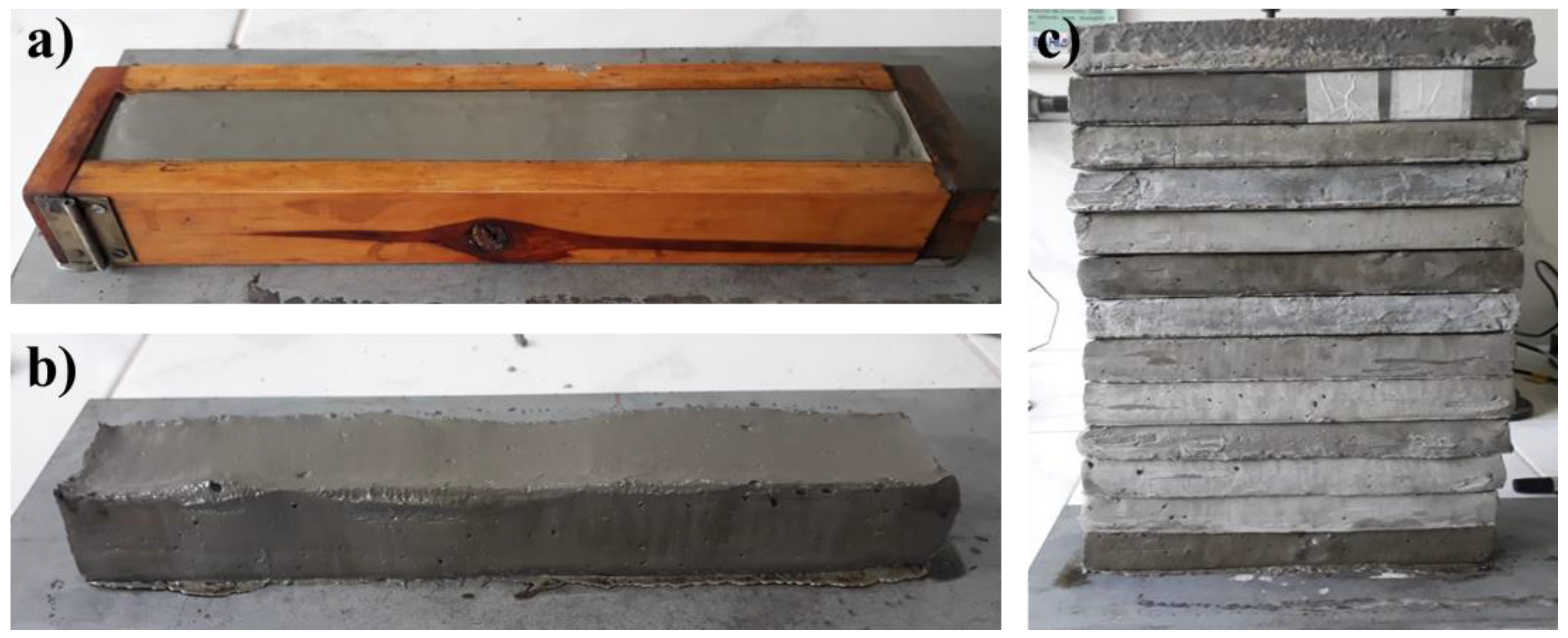
To assess the bearing capacity of the cement pastes, a prismatic mold was used to create a filament as the base layer. The mold dimensions were 40 mm wide, 150 mm long, and 40 mm high. The cement pastes (around 1.5 kg per batch) were mixed using a 4.7 L mortar mixer (Solotest, São Paulo, Brazil) at two different rotational speeds. Initially, the mixer was set to 140 ± 5 rpm for 1 min, followed by a second stage at 285 ± 10 rpm for 2 min. The prepared paste was then placed into the molds in two steps: first, filling half of the mold, followed by manual compaction by rodding 10–15 times using a tamping rod (the one used in the slump test). Next, the remaining portion of the mold was filled, applying new compaction and leveling the top surface (Figure 1a).
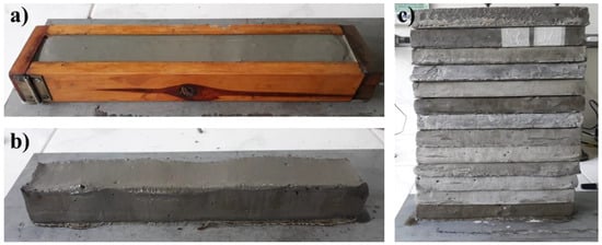
Figure 1.
Photographs of a sample: (a) during molding, (b) after demolding, and (c) undergoing buildability testing with 12 layers above.
Manual compaction was performed to shape and finish the filament. The smooth finish on the sides simulates contour crafting. Small variations in filament density can be seen when using manual compaction or extrusion, as well as with different printing and pumping systems. Even so, researchers with access to a large-scale printer may choose to directly print the base filament rather than molding it.
Rigid cement layers, previously prepared, were then overlapped on the fresh base layer (Figure 1b) at different time gaps (5, 10, 15, 20, and 25 min). The width variation of the filament was measured using a caliper (ZAAS, accuracy of 0.05 mm) to evaluate the load-bearing capacity versus deformation. For stability reasons, a safety limit of 12 layers was set. Each overlapping filament weighs approximately 1 kg, with a weight variation of up to 5% (see Figure 1c). Therefore, the number of layers was equivalent to the weight in kilograms that could be supported.
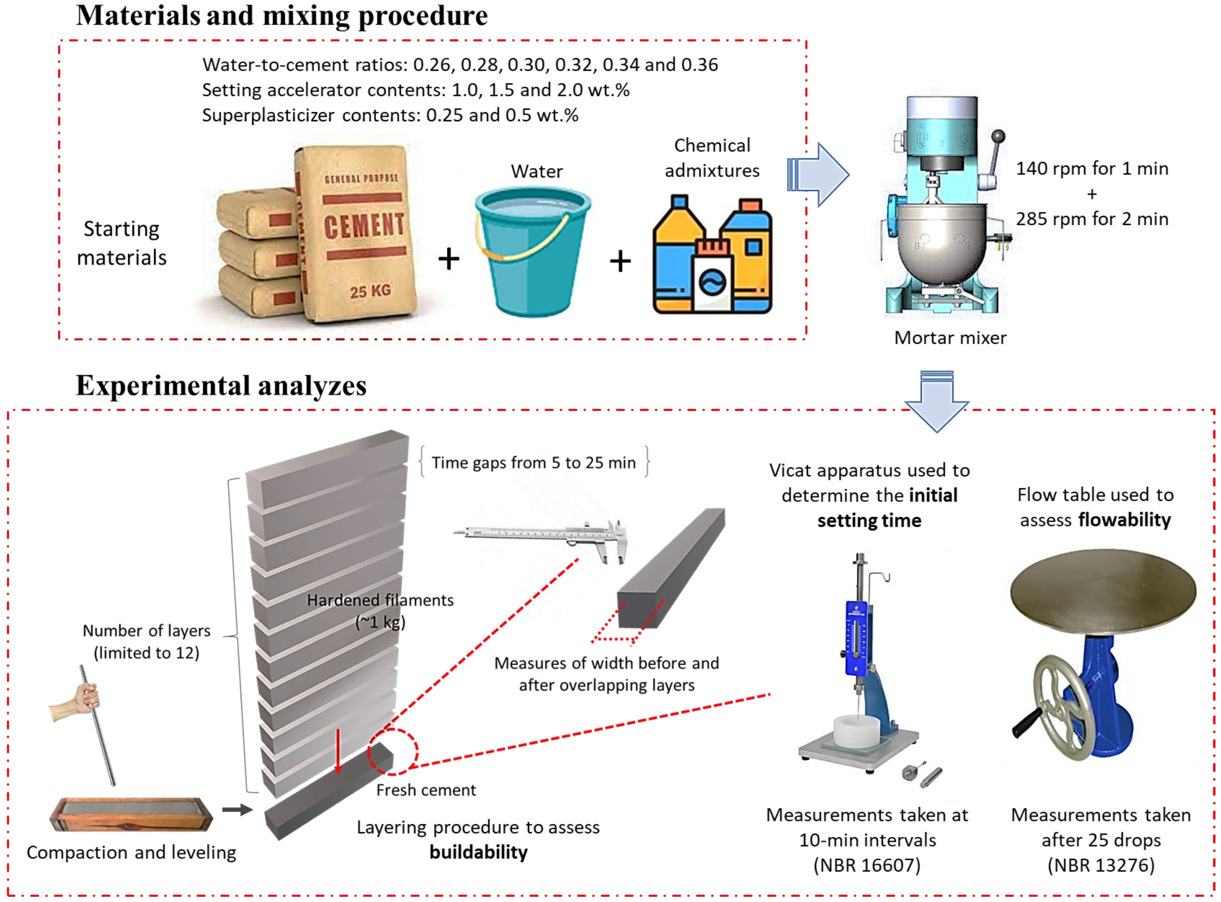
The same procedure was applied to determine the influence of the water content (water to cement ratios of 0.26, 0.28, 0.30, 0.32, 0.34, and 0.36), setting accelerator (at concentrations of 1.0, 1.5, and 2.0 wt.%), and superplasticizer (at concentrations of 0.25 and 0.5 wt.%). This analysis allowed for an indirect evaluation of the structuring rate of the pastes, considering the time gaps between layers based on the size of the construction. This alternative test provides a practical and efficient way to evaluate the buildability of different mix designs without the need for a printer or extruder.
The pastes comprised different water-to-cement ratios (w/c) with and without the addition of the chemical admixtures. Specifically, the setting accelerator was evaluated in the more fluid and less consistent mixtures (w/c ratios of 0.34 and 0.36), while the superplasticizer was assessed in the more consistent mixtures (w/c ratios of 0.26 and 0.28).
The same pastes were also assessed for their flowability/consistency through the flow table test. In this test, the samples were placed in a conical polypropylene mold with a base diameter of 80 mm and a top diameter of 70 mm. The spreading or flowability of the mixture was promoted through twenty controlled impacts. This procedure was adapted from the guidelines of the Brazilian standard NBR 13276 [23]. The average spread of the mixtures was measured in two perpendicular directions using a caliper (ZAAS, accuracy of 0.05 mm). The test was conducted at 10, 30, and 60 min of hydration. The Vicat test was also performed according to NBR NM 65 (2003) [24] to determine the initial setting time. Figure 2 shows the mixing procedure and the experimental analyses adopted in this work.

Figure 2.
Schematic illustration of the experimental procedure adopted to assess the buildability and rheology of the cement mixtures.
3. Results
The results commence by describing the influence of the water/cement ratio on the buildability of the samples, followed by the impact of the setting accelerator and superplasticizer. Subsequently, the relationship between the initial setting time and spreading diameter is discussed in terms of the buildability of the mixtures. Finally, the correlation between the time gap and printing speed in full-scale buildings of varying sizes is examined.
3.1. Buildability in Cement Pastes (Only Cement and Water)
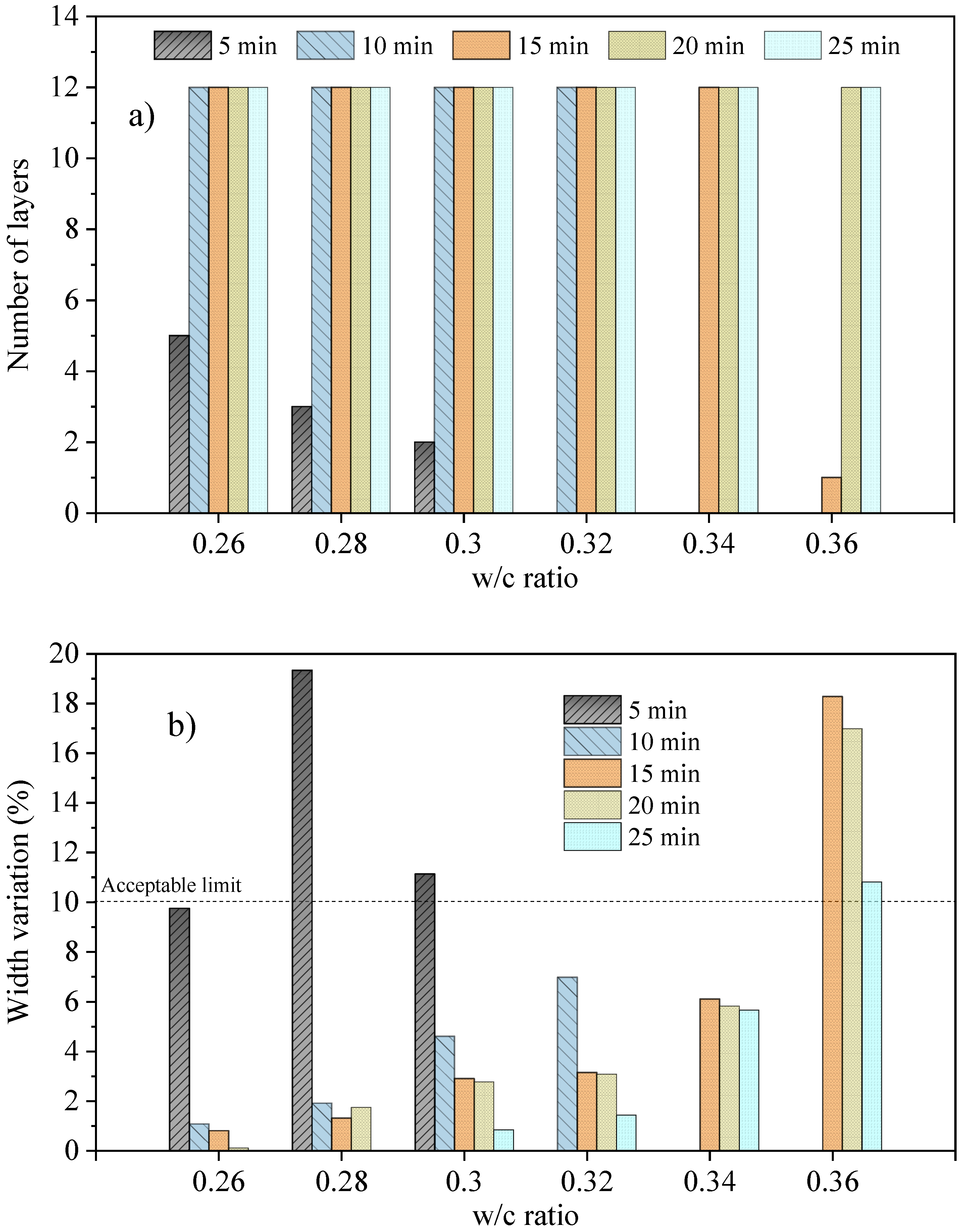
Figure 3 displays the maximum number of layers supported and width variation of cement pastes with different w/c ratios across varying time gaps. As seen in Figure 3a, for the smallest time gap (5 min), overlapping is only possible for pastes with w/c ratios between 0.26 and 0.30, but the maximum number of layers was limited to five, decreasing proportionally to the water content. To support the twelve layers, a minimum time gap of 10 min was required, except for w/c ratios of 0.34 and 0.36 which required minimum time gaps of 15 min and 20 min, respectively.
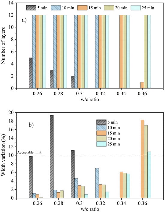
Figure 3.
(a) Maximum number of layers overlapped on the base layer (prismatic fresh paste cement) and (b) width variation of cement pastes with different w/c ratios for different time gaps.
In addition to measuring the load-bearing capacity of the samples, it is essential to simultaneously monitor their deformation. Even if a structure can handle the twelve layers (or more), it may still undergo significant deformation, resulting in a greater variation in the width of the base of the wall in comparison to the top. Cumulatively, the variation in the height of the underlying layers might cause a significant reduction in the overall height of the wall. In this situation, it is necessary to dynamically adjust the height of the nozzle as the wall is built [25].
In this sense, it is crucial to establish an acceptable range of average width variation from the base to the top of the wall to ensure proper buildability in the 3D printing of concrete structures. In this study, a reference deformation limit of 10% in relation to the width variation was set as a criterion for determining the acceptable level of buildability. It is worth noting that variations in layer width can occur due to the variation in paste consistency or material flow through the printing nozzle.
The width variation in 3D printed filaments was also analyzed by other researchers. Kazemian et al. [11] proposed a testing procedure for construction-scale 3D printing mixtures to assess workability in terms of print quality, shape stability, robustness, and printability window. After conducting numerous experiments, they concluded that a 10% error in the target width is a reasonable threshold for accepting or rejecting printed layers. In another study conducted by Ma et al. [12], samples that successfully demonstrated construction capacity exhibited a maximum deformation of 10% of the width after stacking. The results obtained from these studies were utilized to establish the deformation limit applied in this work.
For improved control on the construction site, real-time data on width variation of layers can be assessed through sensors integrated with the printing system, facilitating adjustments during printing. For instance, excessive layer deformation in the underlying layers could be mitigated by reducing the printing speed during printing to extend the time gap between layers, providing additional time for the lower layers to consolidate. Mendřický and Keller [26] show how 3D scanning can be used to quickly assess the dimensional stability of 3D-printed concrete elements.
As depicted in Figure 3b, pastes with w/c ratios ranging from 0.26 to 0.32, which can effectively support all layers with a time gap of 10 min, presented width variations within the acceptable deformation limit. Similarly, pastes with a w/c ratio of 0.34 were also considered buildable, with acceptable deformation for time gaps from 15 min. However, for pastes with a w/c ratio of 0.36, although they could withstand the maximum load with a time gap of 15 min, the resulting deformation was too significant to be considered buildable. To achieve an acceptable deformation, a longer time gap of at least ~30 min would probably be required.
The width variation for w/c ratios of 0.26, 0.28, and 0.30 at a time gap of 5 min was found to be influenced by both the water content and the number of layers. Interestingly, despite having a lower water content, the width variation for the w/c ratio of 0.28 was found to be greater than pastes with a w/c ratio of 0.30, likely due to the additional weight of one extra layer.
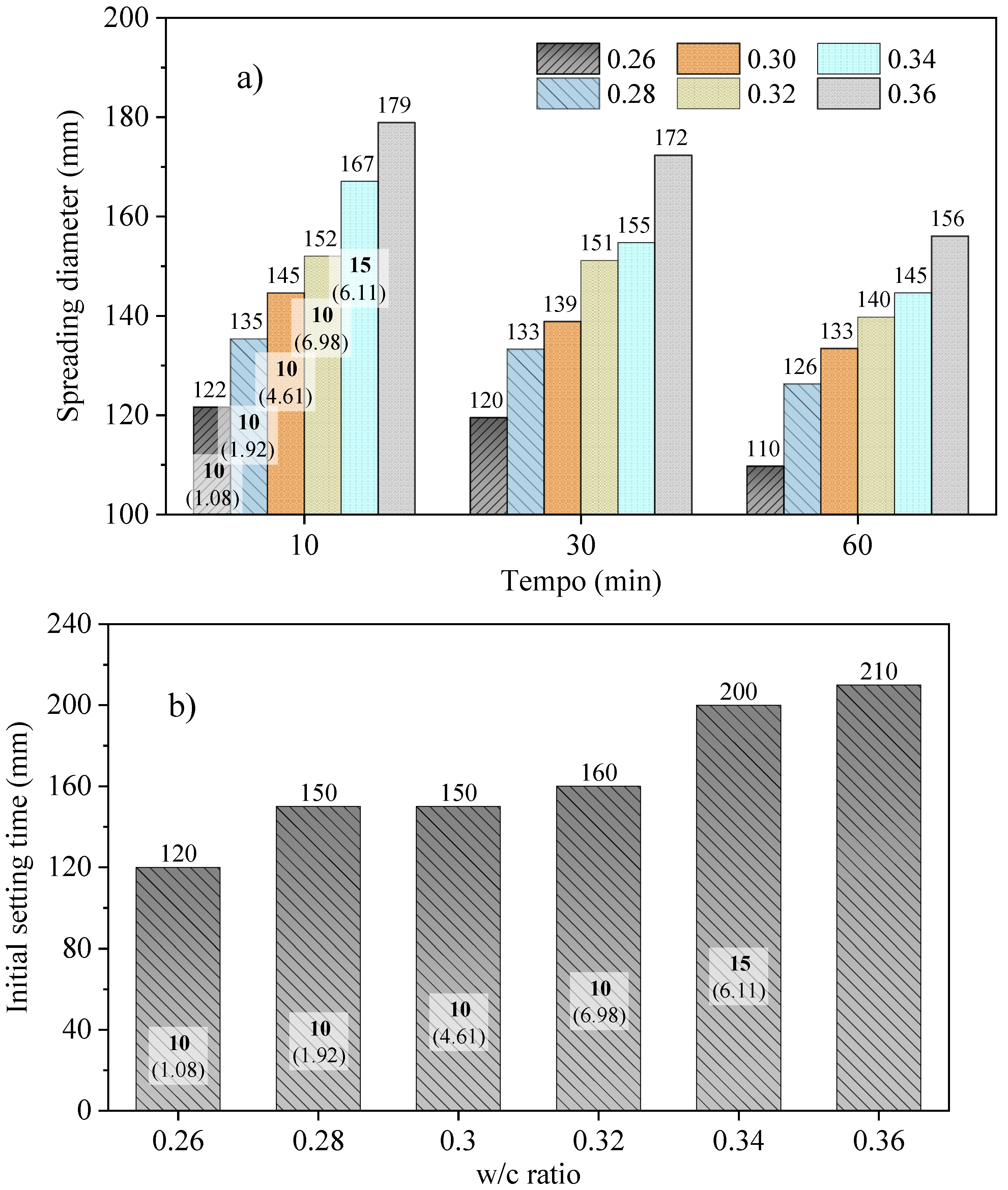
Figure 4a illustrates the spreading diameter of cement pastes at different time intervals of 10, 30, and 60 min of hydration and with varying w/c ratios. For easier interpretation, the minimum time gaps (numbers in bold) required for the pastes to be considered buildable, as well as the variations in layer width (numbers in parentheses), are also shown.
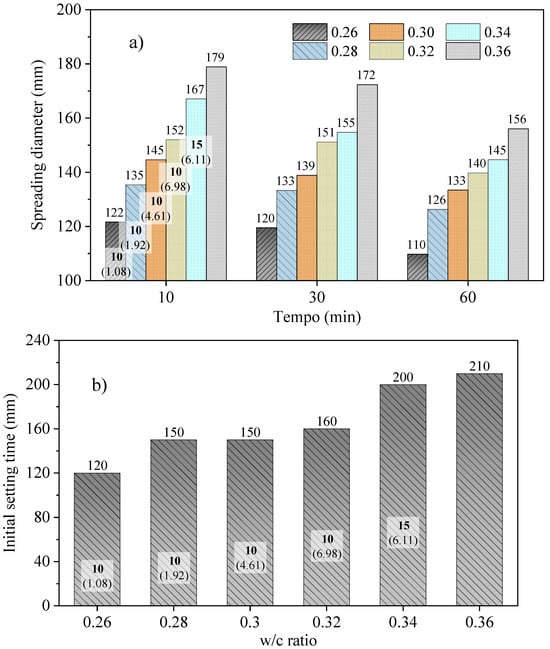
Figure 4.
Spreading diameter with time (a) and initial setting time (b) for cement pastes at various w/c ratios. The time gap (bold numbers) and width variations (in parentheses) are also indicated.
It is noteworthy that the mixtures became buildable for spreading diameters below 170 mm when the time gap was at least 15 min, as observed for the w/c ratio of 0.34. In the case of w/c ratios from 0.26 to 0.32, the reduction of the spreading diameter below 155 mm permitted a decrease in the time gap to 10 min. As the spreading diameter decreased, the variation in layer width also diminished (from ~7% to ~1%). Although not practical, this may also suggest that the time gap of the paste with a w/c ratio of 0.34 can be reduced from 15 min to 10 min after 30 min from mixing or after 60 min for the paste with a w/c ratio of 0.36.
Figure 4b shows the setting time results for the Vicat test. The buildable samples with width variation within an acceptable range have initial setting times ranging from 120 min to 160 min at a time gap of 10 min. Above this range, it is necessary to increase the time gap to become buildable.
In addition to the evident delay in the onset of setting time with increasing w/c ratios, it is noteworthy that buildable pastes exhibit an initial setting time beginning at 120 min, i.e., when all twelve layers have been placed, for the w/c ratio of 0.34. Therefore, the load-bearing capacity is primarily governed by the frictional forces between the cement particles, which define the paste’s consistency. The main hydration products (C-S-H and CH) exert minimal or negligible influence, and ettringite, the first hydrated product formed, has little significance (likely comprising no more than 3% of the paste during this period) [27,28].
3.2. Effect of the Presence of a Setting Accelerator
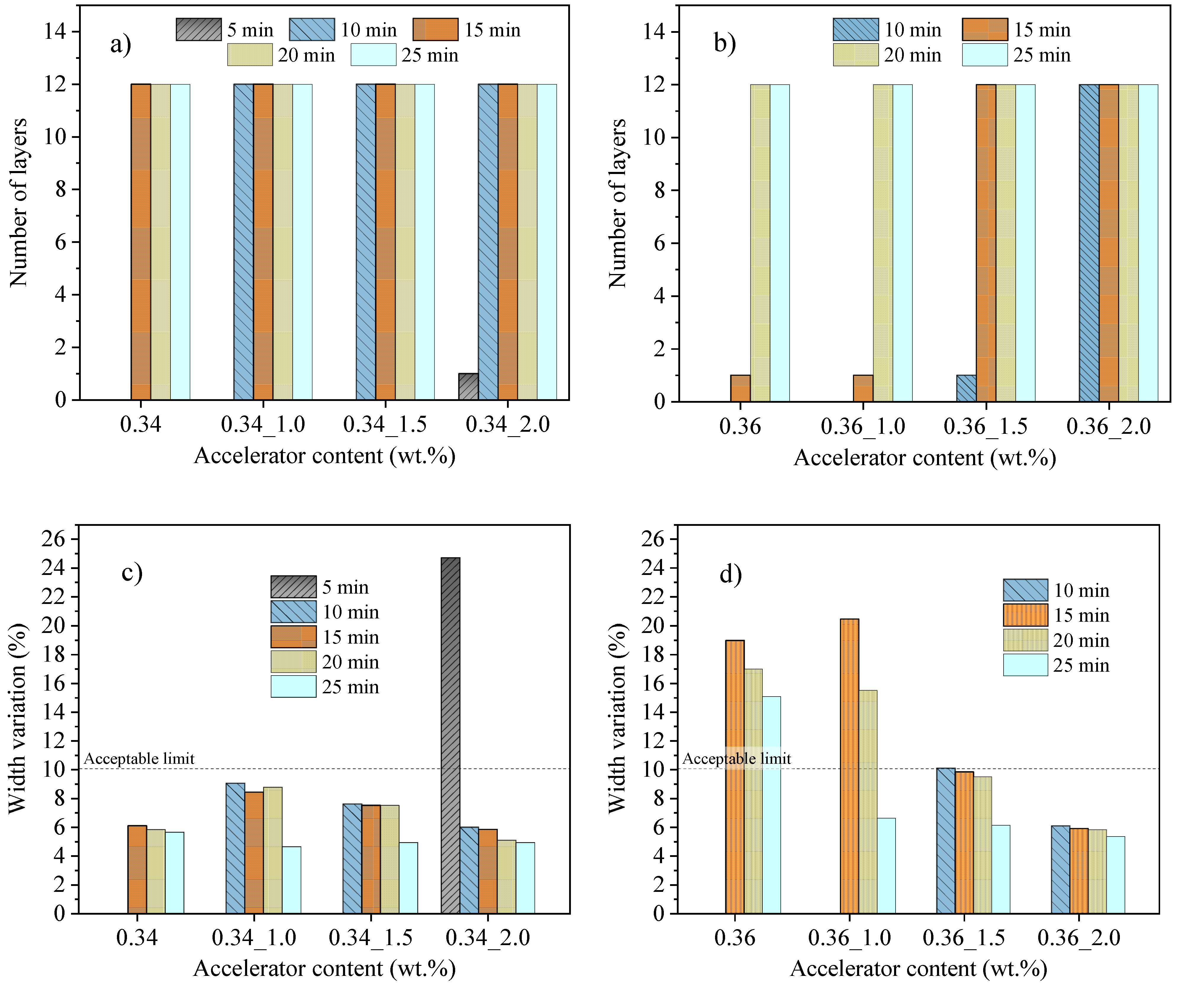
The influence of the setting accelerator was assessed in the more fluid mixtures, specifically those with w/c ratios of 0.34 and 0.36, with the objective of enhancing their buildability (see Figure 5). For mixtures with a w/c ratio of 0.34 (Figure 5a), the time gap required to achieve maximum load-bearing capacity could be reduced from 15 min to 10 min with a 1 wt.% accelerator. In the case of pastes with a w/c ratio of 0.36 (Figure 5b), a 1 wt.% accelerator did not lead to additional load-support, but a time gap of 20 min could be decreased to 15 min with a 1.5 wt.% accelerator and to 10 min with a 2.0 wt.% accelerator.

Figure 5.
Number of layers supported and width variation of cement pastes with w/c ratios of 0.34 (a,c) and 0.36 (b,d) at various accelerator contents and time gaps.
It is interesting to note that the addition of the setting accelerator had a limited effect on reducing the width variation of pastes with a w/c ratio of 0.34 (Figure 5c), despite improving the load-bearing support. The width variation even increased with a 1.0–1.5 wt% of the additive. Its main benefit in this case was the ability to decrease the minimum time gap while still maintaining width variation within the recommended range.
For pastes with a w/c ratio of 0.36 (Figure 5d), the accelerator was more effective. With a 1.0 wt.% additive, the width variation decreased to below 10% for a time gap of 25 min. By increasing the accelerator concentration to 1.5 wt.%, the samples became buildable with time gaps of 15 min. Further, with a 2.0 wt.% accelerator, the samples were buildable with time gaps as low as 10 min.
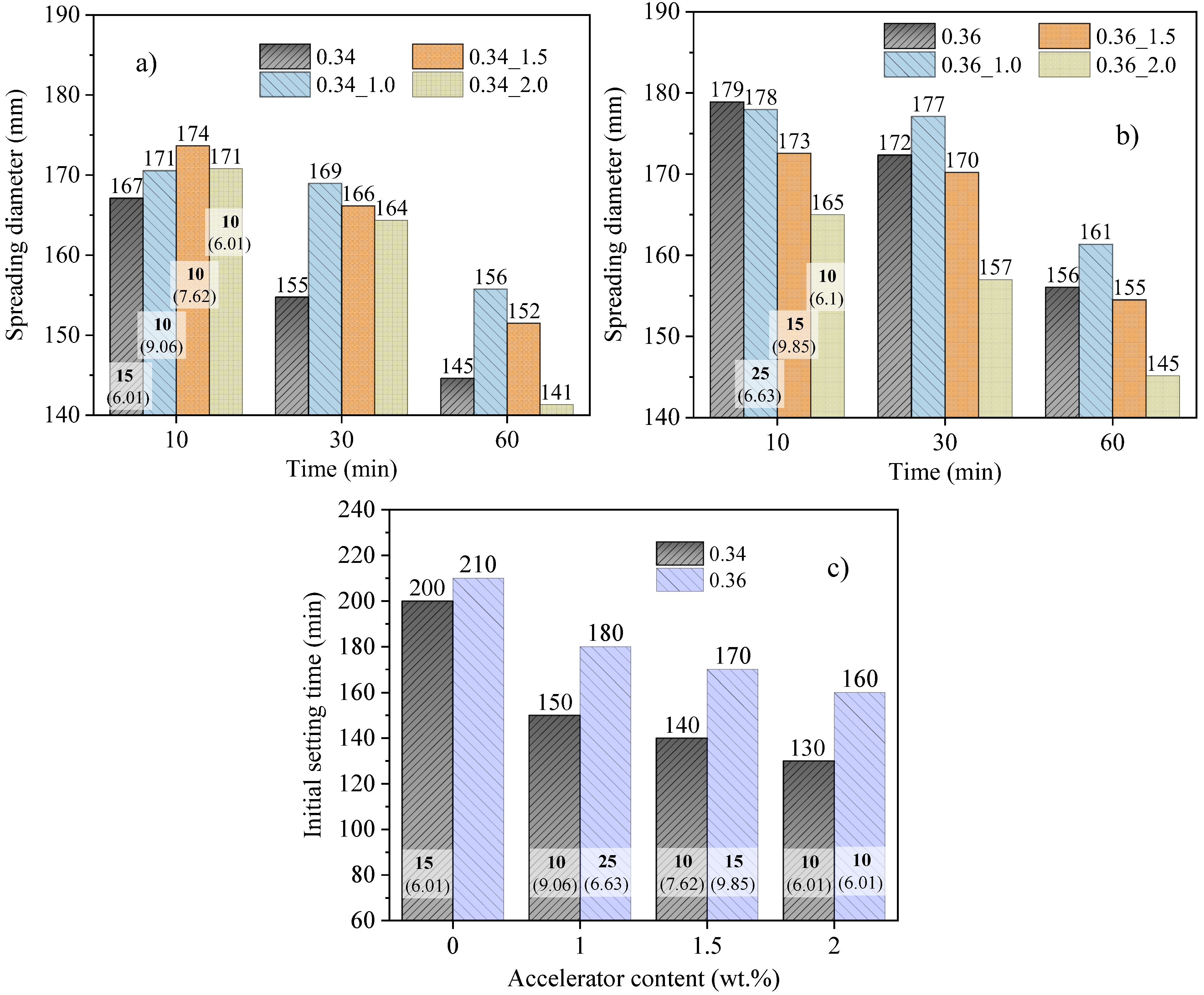
Figure 6 illustrates the spreading diameter and initial setting times of samples containing the setting accelerator. Analogous to the width variation, the spreading diameter also increased with a 1.0 and 1.5 wt.% of the accelerator for the w/c ratio of 0.34 (Figure 6a), surpassing the diameter of the paste without the additive during the first hour of hydration. The increase in spreading diameter also occurred in samples containing a 2.0 wt.% of the accelerator for up to 30 min. Despite the larger spreading diameter observed in the mixtures with the additive, the time gap could be reduced from 15 min (without additive) to 10 min. In the case of the w/c ratio of 0.36 (Figure 6b), the effect of the additive on the increase in the spreading diameter is only evident for a 1 wt.% concentration.
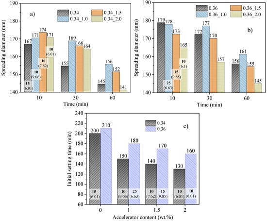
Figure 6.
Spreading diameter (a,b) and setting times (c) for the cement pastes with w/c ratios of 0.34 and 0.36 with different accelerator contents. The time gap (bold numbers) and width variations (in parentheses) are also indicated.
This phenomenon has been consistently observed in previous studies. Souza et al. [6] conducted experiments using stationary reometry and found that pastes containing 1.0% calcium chloride and 2.0% of a commercial setting accelerator exhibited a slight reduction in yield stress during the initial half hour of hydration. Higher concentrations of these additives led to a substantial increase in yield stress. Similarly, Boháč and Novotný [29] observed a retardation effect in samples with up to 1% CaCl2 during the early hydration of Portland cement. A significant acceleration effect was observed for higher dosages. The authors postulated that the formation of ettringite is delayed at lower CaCl2 contents. While this observation could potentially explain the increased fluidity of the samples, further comprehensive studies are necessary to fully elucidate and understand this phenomenon.
Similar to cement pastes without additives, which can be worked with for a time gap of 10 min and have initial setting times ranging from 120 to 160 min, the pastes with the accelerator exhibited initial setting times between 130 and 160 min (Figure 6c). Longer initial setting times necessitated extended time gaps or could potentially render the mixture non-buildable.
3.3. Effect of the Presence of a Superplasticizer
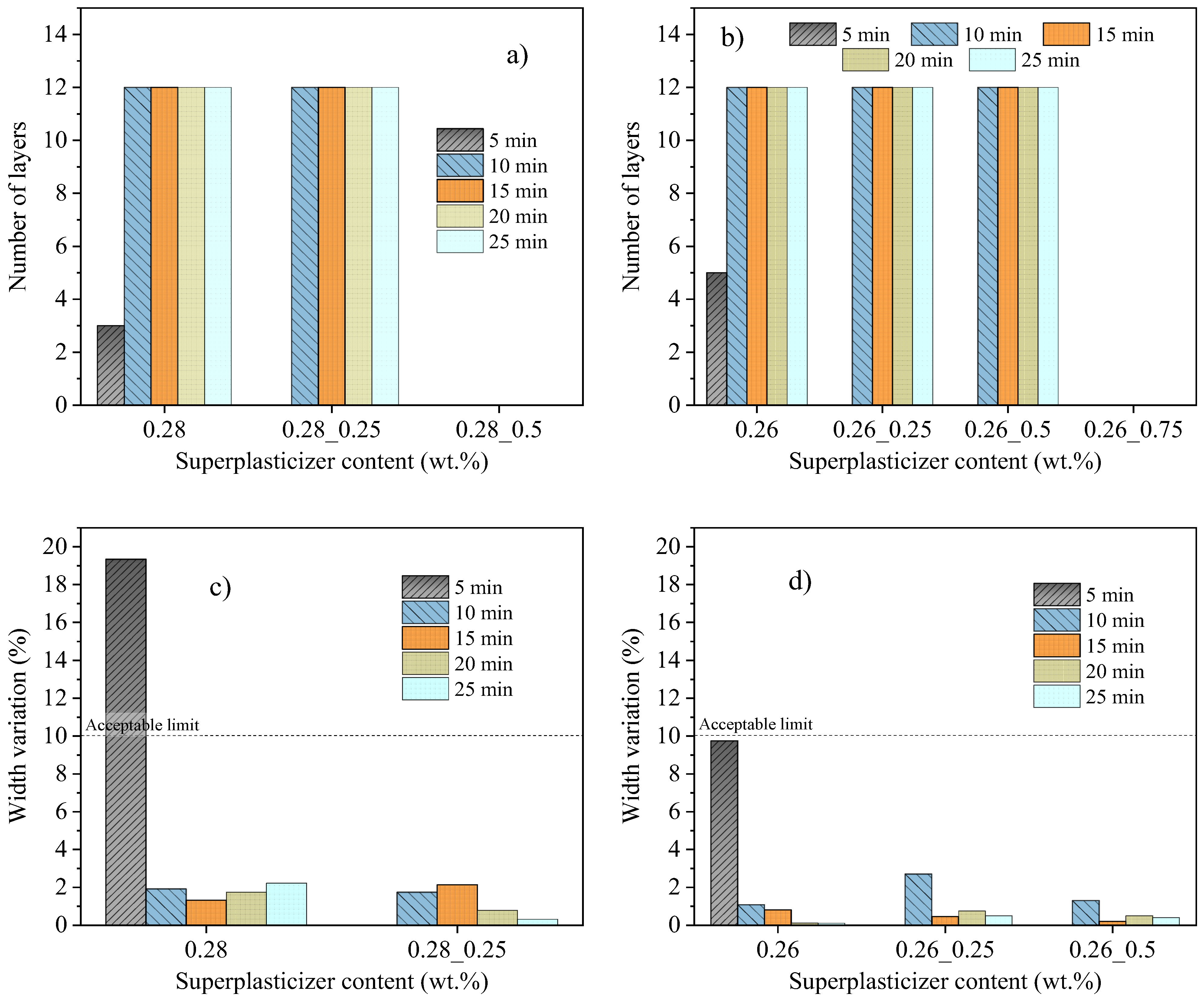
The impact of the superplasticizer was evaluated in the more consistent mixtures, specifically those with the lowest w/c ratios of 0.26 and 0.28, aiming to improve their flowability while still ensuring buildability (refer to Figure 7).
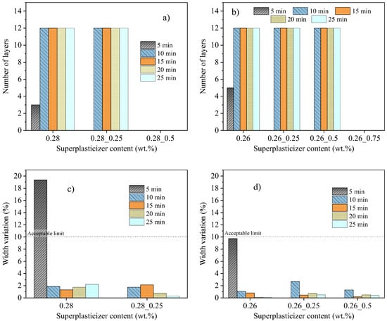
Figure 7.
Number of layers supported and width variation of cement pastes with w/c ratios of 0.28 (a,c, respectively) and 0.26 (b,d, respectively) with different superplasticizer contents and time gaps.
For a w/c ratio of 0.28, the load-bearing capacity was minimally affected by a 0.25 wt.% of superplasticizer (Figure 7a). With a 0.5 wt.%, however, all mixes became too fluid, with no buildability. For a w/c ratio of 0.26 (Figure 7b), the load-bearing capacity was minimally affected by 0.25 wt.% or 0.5 wt.% for time gaps of at least 10 min and became excessively fluid with 0.75 wt.%. As shown, the superplasticizer had minimal impact on width variation in buildable samples capable of supporting 12 layers (see Figure 7c,d).
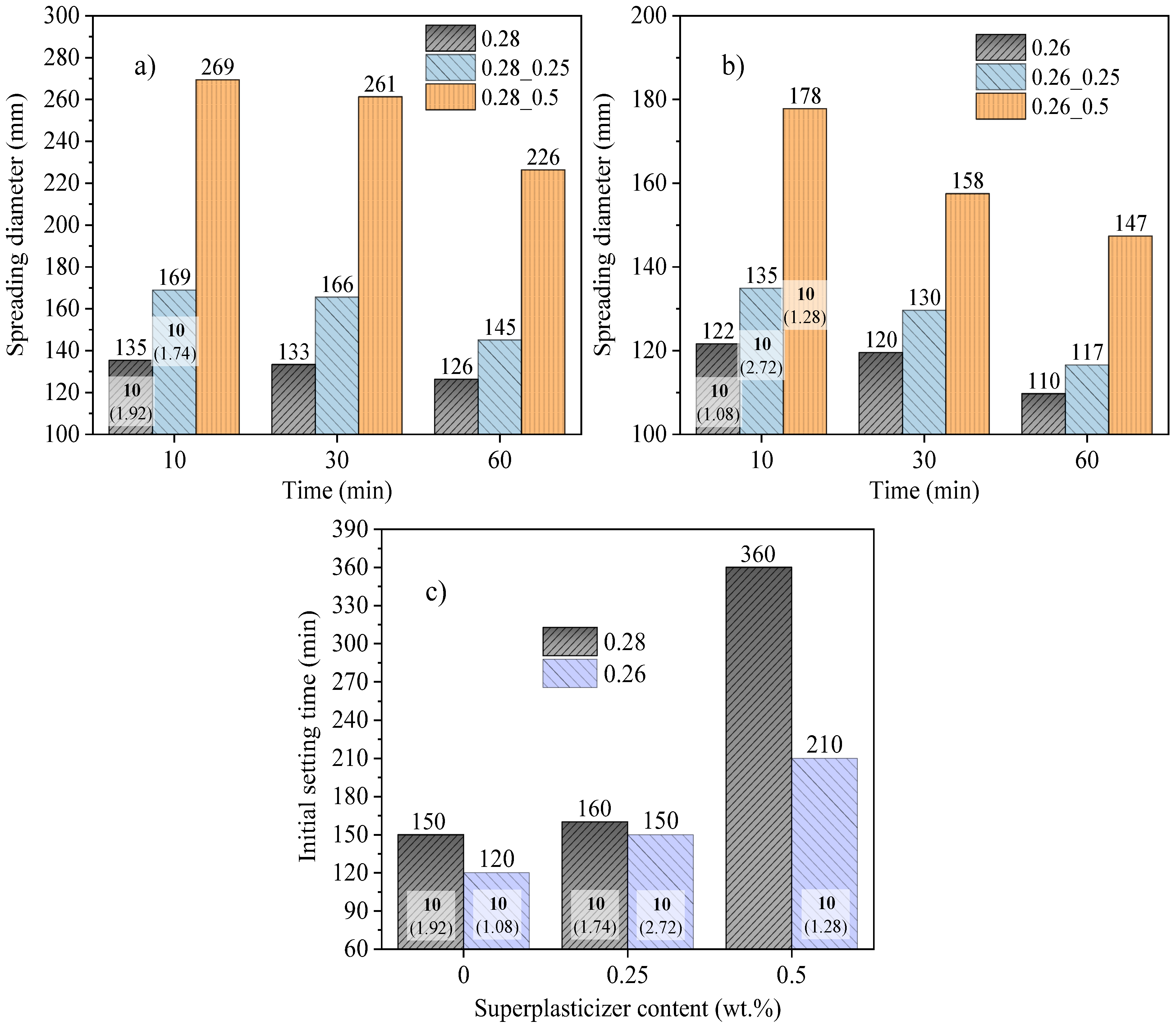
Figure 8 illustrates the spreading diameter and initial setting times of samples containing the superplasticizer for cement pastes with w/c ratios of 0.26 and 0.28. By adding up to 0.25% of superplasticizer, it was possible to enhance the flowability of cement paste with a w/c ratio of 0.28 (Figure 8a) while maintaining buildability (see Figure 7a,c). In the case of a w/c of 0.26 (Figure 8b), the content of superplasticizer can be increased to 0.5% without any adverse effects on buildability (see Figure 7b,d).

Figure 8.
Spreading diameter of cement pastes: (a) with a w/c ratio of 0.28, (b) with a w/c ratio of 0.26, both with 0.25 and 0.5% superplasticizer contents, and (c) the initial setting time for both w/c ratios with the same superplasticizer contents. The standard deviation of the measures was under 5%. The bold numbers represent the minimum time gap for being considered buildable (12 layers and width variation less than 10%) and the numbers between parentheses are the width variation percentual.
It is interesting to observe that a paste with 0.26_0.25 wt.% superplasticizer (Figure 8b) presenting a spreading diameter of 178 mm is considered buildable with time gaps of 10 min. In contrast, a paste with no additive and a w/c ratio of 0.36, despite having a spreading diameter of 179 mm, does not exhibit buildability (see Figure 3 and Figure 4a). This behavior underscores the benefits of utilizing superplasticizers, as they enhance the flowability of concentrated suspensions under increased stress conditions (such as pumping) while simultaneously preserving buildability under lower stress conditions, like the weight of adjacent filaments.
Hence, the spreading diameter, as an indicator of buildability, becomes constrained in the presence of additives, such as superplasticizers, which can enhance fluidity while maintaining load-bearing capacity. Alternatively, one can assess the spreading diameter at longer hydration times, such as 30 or 60 min, as the effectiveness of the additive diminishes with the progression of the hydration process. This correlation will be further discussed in the subsequent section.
Regarding the initial setting times, most of the samples that were buildable for time gaps of 10 min displayed initial setting times below 160 min. Analogous to spreading diameter, the cement pastes with a w/c ratio of 0.26 and 0.5 wt.% superplasticizer demonstrated excellent buildability despite having a longer setting time of 210 min.
3.4. Relationship between Initial Setting Time, Spreading Diameter and Buildability
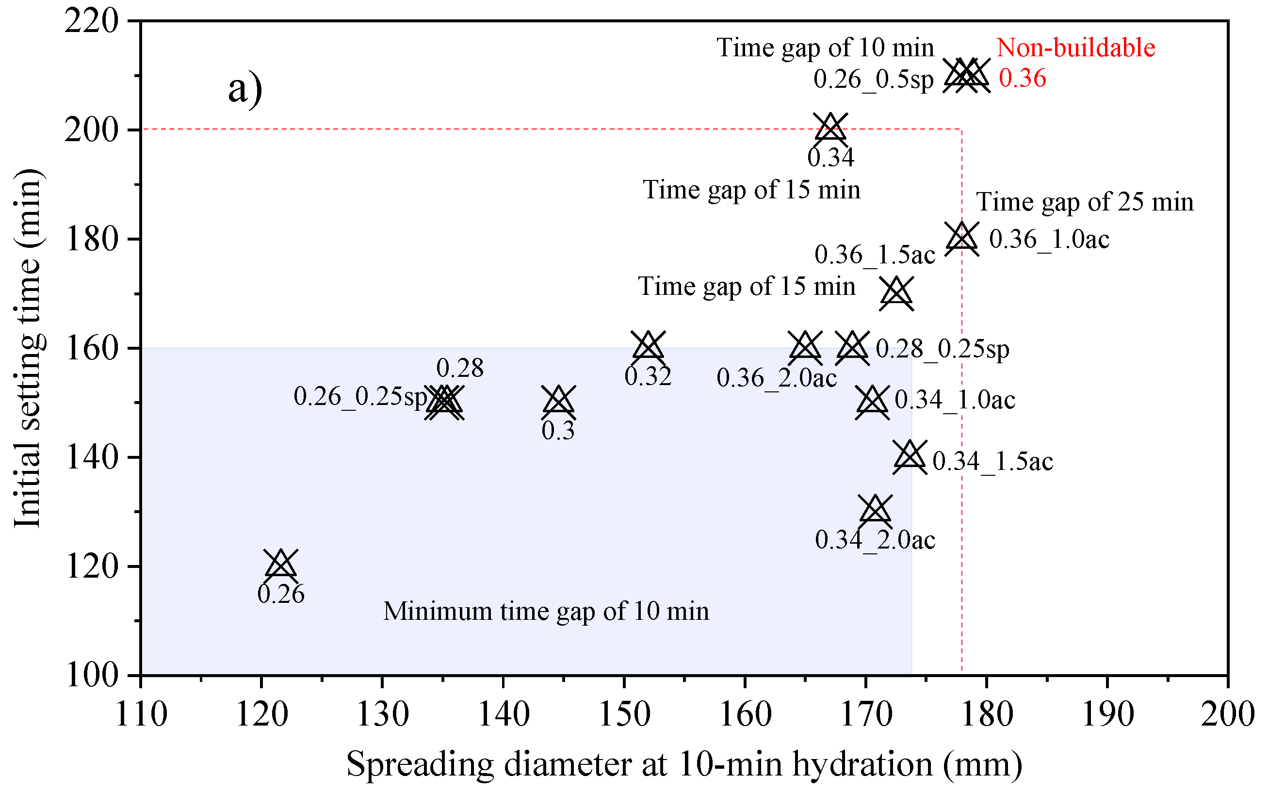
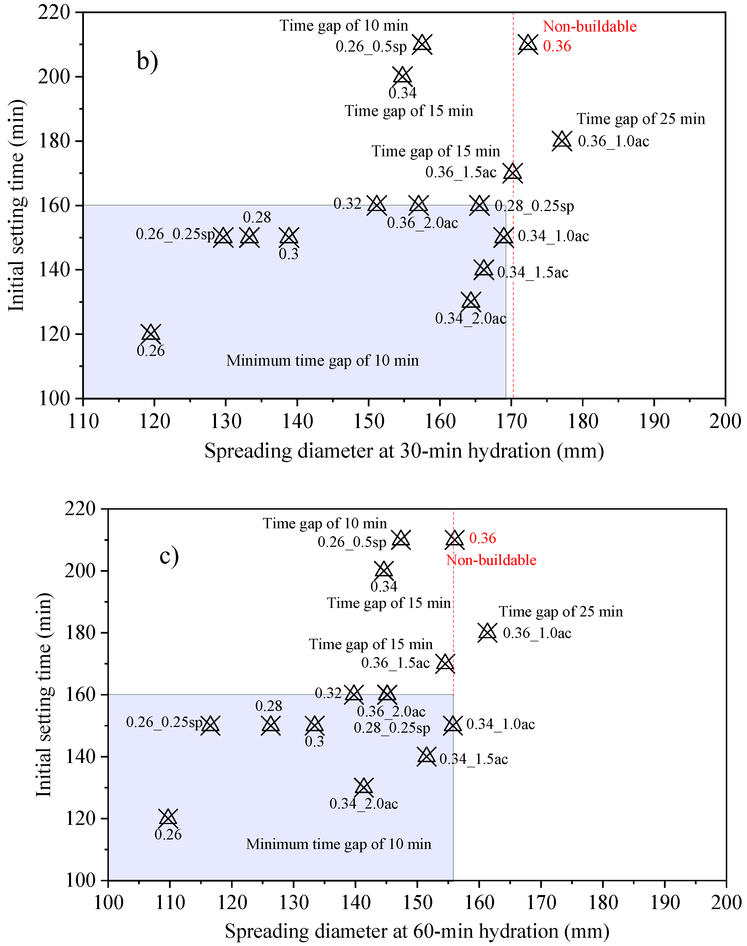
Figure 9 shows the correlation between the initial setting time and spreading diameter of all pastes (with and without additives) measured at 10 min, 30 min, and 60 min of hydration. It is observed that pastes with a spreading diameter below 173 mm at 10 min of hydration and an initial setting time of up to 160 mm (blue zone) exhibited buildability with time gaps of 10 min or more (Figure 9a). Samples with spreading diameters up to 178 mm and initial setting times of up to 200 min demonstrated buildability across varying time gaps ranging from 15 to 25 min (dashed lines). It can also be noted that the mixtures with a w/c ratio of 0.26 and a 0.5 wt.% of superplasticizer and with a w/c ratio of 0.36 without any additive have similar initial setting times and spreading diameters, but they exhibit significantly different buildability characteristics. While the former demonstrates excellent buildability with a time gap of 10 min between layers, the latter is deemed non-buildable for time gaps less than 30 min.
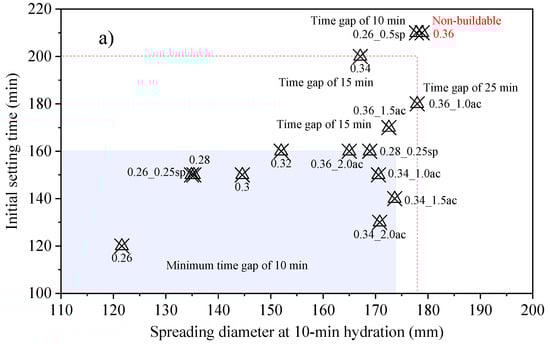
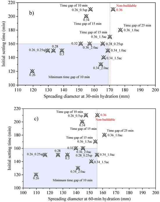
Figure 9.
Correlation between initial setting times and spreading diameter measured after (a) 10 min, (b) 30 min, and (c) 60 min of hydration.
When the spreading diameter was evaluated at 30 min of hydration, the maximum spreading of the mixtures that were buildable with time gaps from 10 min decreased from 174 mm (at 10 min) to 169 mm. There is also a distinction between the 0.26_0.5sp and 0.36 samples. While the spreading diameter of the former reduced from 178 mm (at 10 min) to 157 mm (at 30 min), the reduction for the latter was from 179 mm to 172 mm, respectively. With a larger difference in spreading diameter between these mentioned pastes, a new limit of 170 mm could be established for the spreading diameter to ensure buildability with time gaps of 10 or 15 min. For spread measurements at 60 min of hydration, the limit would be a spreading of 156 mm. However, the same spreading measurement was obtained for the non-buildable sample with a w/c ratio of 0.36. The assessment of buildability becomes more accurate when considering both the spreading diameter and initial setting time. However, it is important to note that there may be cases where certain samples fall outside the ideal range but still demonstrate satisfactory buildability.
Numerous studies have aimed to establish a correlation between the outcomes of flow table tests and the performance of concrete or mortar in the 3D printing process, with the objective of defining appropriate parameters for buildability. However, comparing these studies is challenging due to variations in the standards followed, resulting in differences in mold specifications and the number of drops (refer to Table 1). Tay et al. [5] conducted their study based on American standard specifications and identified an acceptable range of spreading diameters between 150 and 190 mm for 3D printing. In contrast, Sun et al. [30], who followed the Chinese standard, suggested a suitable range of 160 to 190 mm for printing. Another study by Ma et al. [12], also using the Chinese standard as a reference, found a slightly different result with an appropriate spreading diameter range of 174 to 210 mm. These studies highlight the importance of determining suitable ranges of spreading diameters to ensure the necessary fluidity of the mixture for the 3D printing process. However, it should be noted that these ranges may vary depending on the specific characteristics of the mixture, the equipment used, and, as emphasized in this study, the chosen time gap.

Table 1.
Standards and specifications for flow table tests vary across different countries.
3.5. Relationship between Time Gap and Printing Speed for Different Residential Constructions
As mentioned above, the time gap between layers is a crucial parameter in 3D printing for construction, and it is affected by both the printing speed and the size of the structure. A faster printing speed allows the printer nozzle to move quickly across the printing area, reducing the time required for each layer to be printed. However, it can also compromise the structural integrity of the printed object, as each layer may not have enough time to achieve strength before the next layer is printed. In contrast, a slower printing speed can lead to better load-bearing capacity, but it can also result in cold joints between layers with excessively long time gaps, reducing the overall strength of the wall. Moreover, a slower printing speed increases the time required to complete the printing process, reducing the efficiency of the construction process. Therefore, finding the optimal printing speed is critical to achieving a balance between speed and structural integrity. The optimal printing speed varies depending on various factors, such as the structuration rate of the material, the size and complexity of the building being printed, and the desired level of precision and finishing.
While certain printers can achieve maximum speeds of up to 1000 mm/s, most companies in the 3D printing industry for construction typically do not exceed 250 mm/s. Table 2 provides a comprehensive overview of leading companies in the industry, showcasing their respective printing speed ranges, along with other relevant details about their technology and construction methodologies.
Table 2.
Information on companies capable of constructing large-scale printed buildings and the specifications of their printers.
While 3D printers have the potential to operate at high speeds, it is common for construction processes to adhere to a maximum speed of 150 mm/s. This limitation arises from various factors, including the rheological properties of the printing materials and safety considerations. Notably, in the United States of America (USA), the Occupational Safety and Health Administration (OSHA) has recommended a speed limit of 250 mm/s for manually controlled robotic structures with operators in close proximity to the equipment. This safety guideline, issued by the United States Department of Labor between 2019 and 2021, emphasizes the importance of maintaining a controlled and safe operating environment.
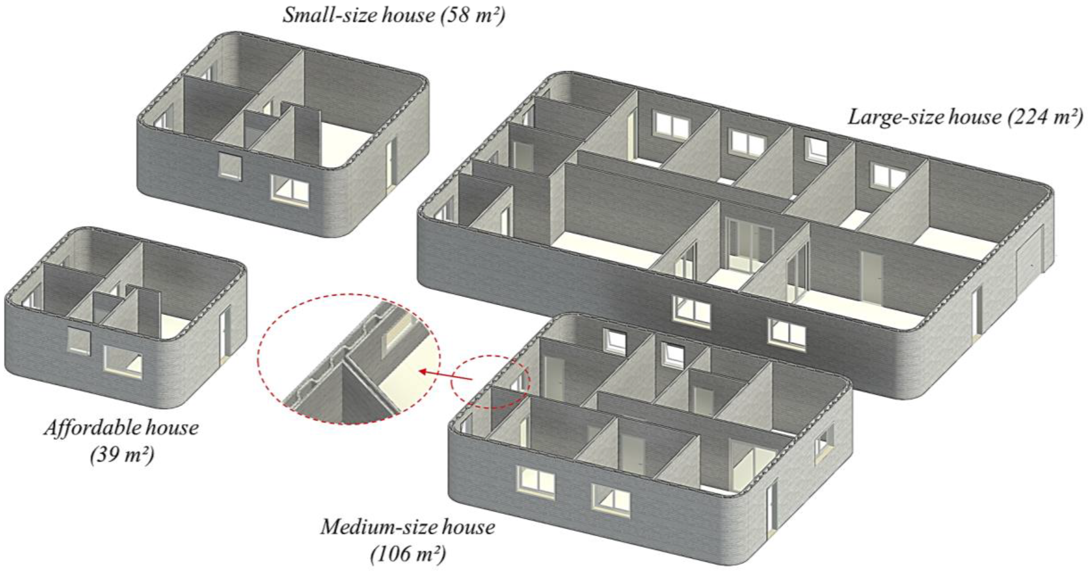
The printing speed and size of the construction significantly impact the time gap between filaments, which is influenced by the printer’s capacity and the rheological properties of the printing mixture. To illustrate the relationship between time intervals, printer speed, and building size, we’ve devised four distinct 3D-printed residential construction projects, each with varying dimensions. These projects encompass a large-size house of 224 m2 with a printing perimeter of 316.8 m, a medium-size house of 106 m2 with a printing perimeter of 230.8 mm, a small-size house with 58 m2 and a printing perimeter of 133.1 mm, and an affordable house with 39 m2 and a printing perimeter of 110.2 mm (see Figure 10). The architectural design incorporates double walls, with exterior walls connected by internal concrete filaments arranged in a zigzag pattern. Detailed floor plans are available in the Supplementary Material. The inspiration for these building designs derives from a study conducted by the Apis Cor company, which evaluated the structural integrity of 3D-printed walls in comparison to conventional concrete masonry walls [30]. It is worth mentioning that the company used a similar filament width as utilized in this study. The gaps between the internal filaments can be filled with insulating materials or alternatively with reinforced concrete to create load-bearing columns.
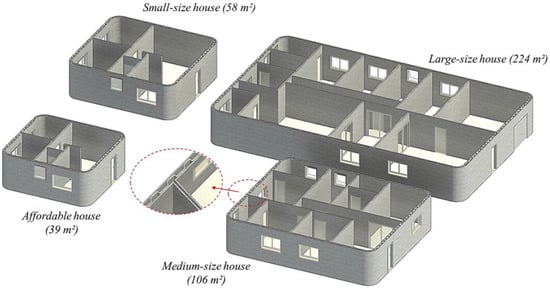
Figure 10.
Visualization of residential building projects for 3D printing.
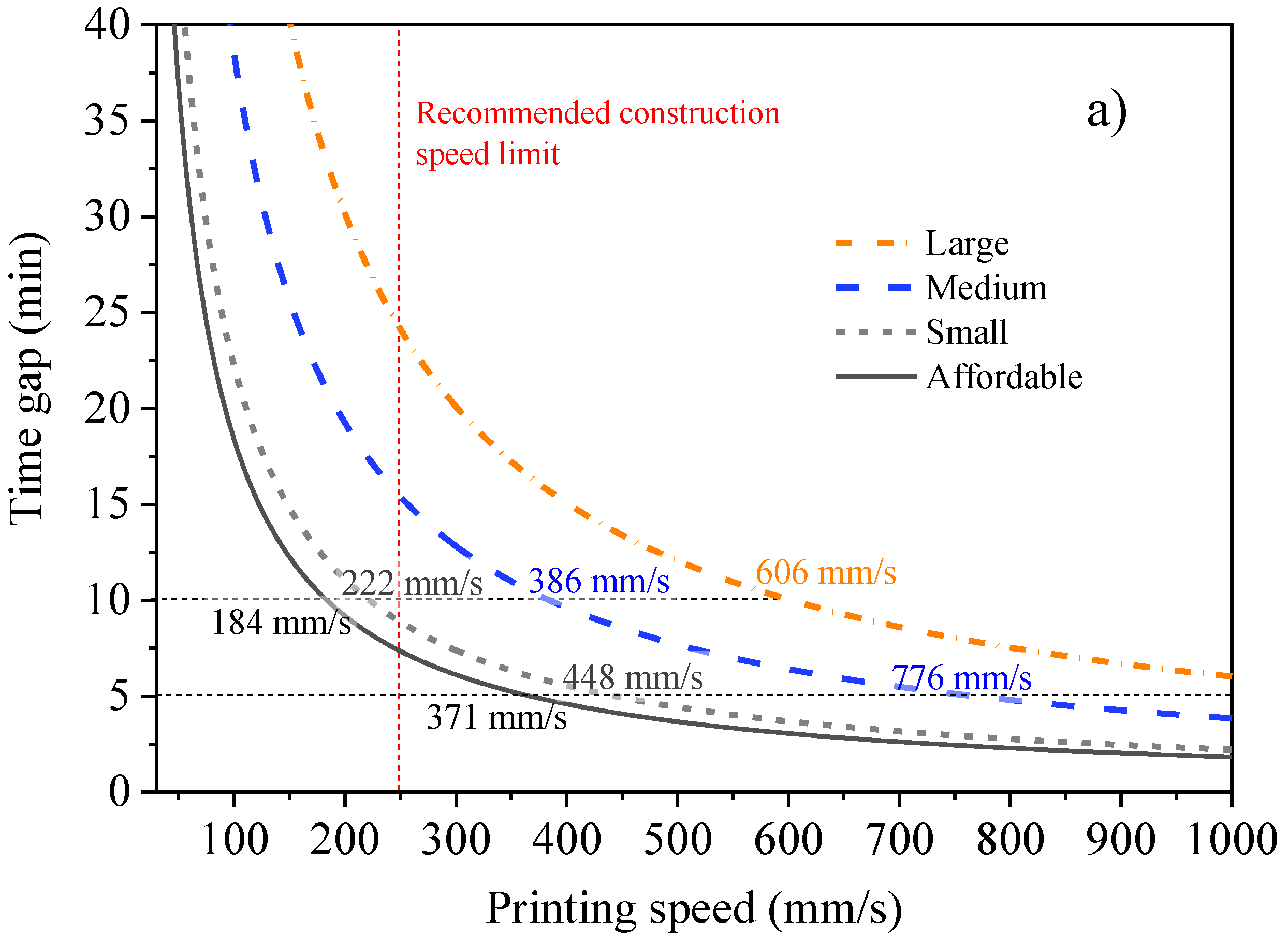
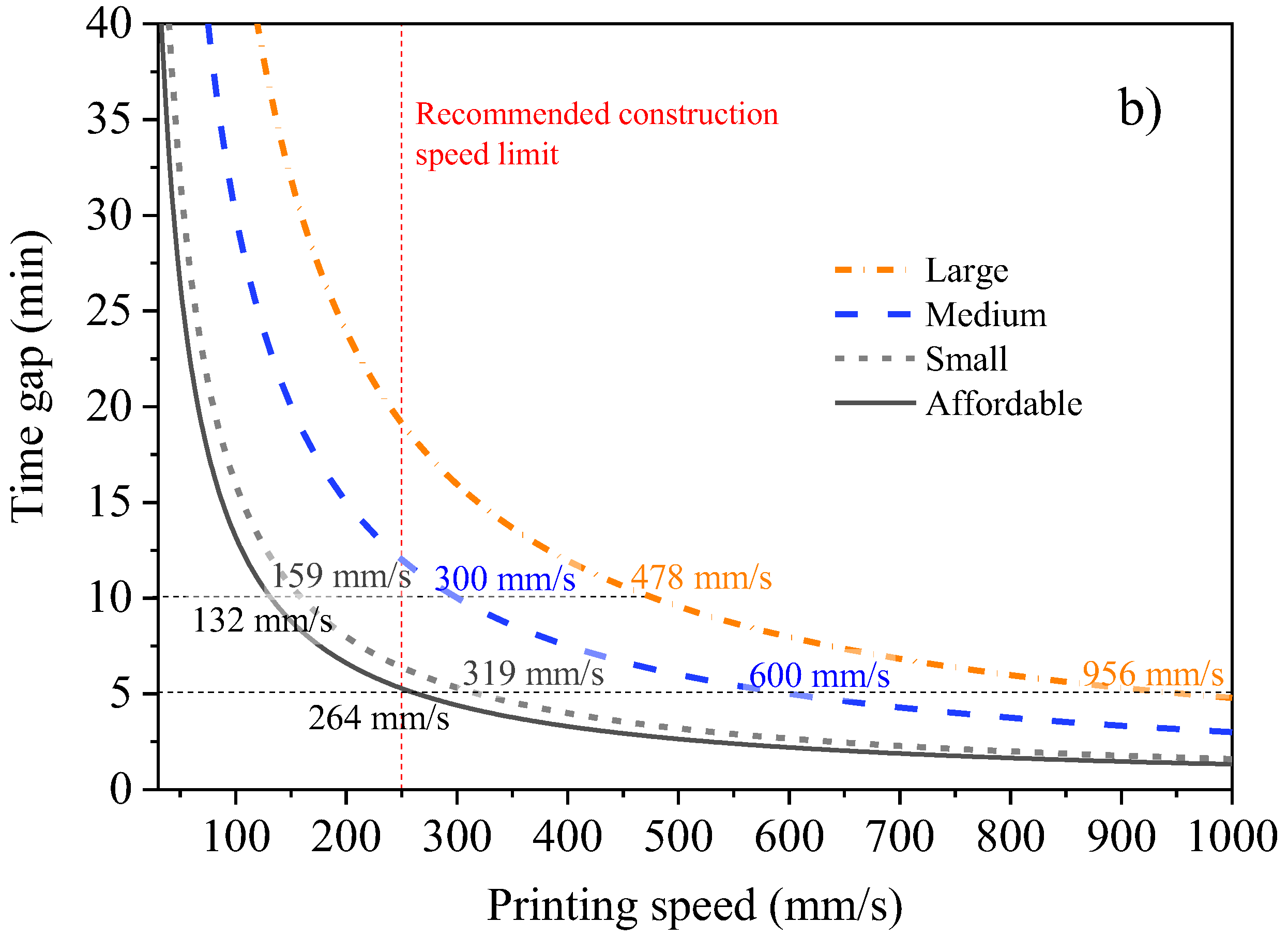
Based on the designs of the residential buildings, the required printing speed for various construction scenarios and time intervals could be estimated (see Figure 11). The curves were derived from the print path length, including the connecting filaments of the outer walls in Figure 11a and excluding the connecting filaments in Figure 11b. The time necessary for the printer to complete one full revolution (time gap) was also calculated as a function of the printing speed. It is important to note that some 3D-printed building designs utilize horizontal metal bars and/or wire screens for wall connections, resulting in a significant reduction in the building’s perimeter. In this study, it was observed that the removal of connection filaments led to a reduction in print path length of approximately ~28% for the two smaller buildings and ~21% for the two larger buildings.
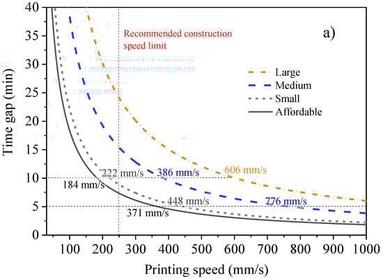
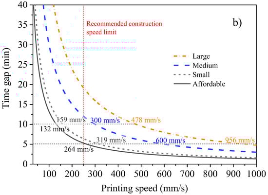
Figure 11.
Relationship between time gap and printing speed for different residential constructions, including relationships (a) incorporating and (b) excluding the internal filament in perimeter calculations.
For a 10 min time gap, during which most of the previously reported mixtures are considered buildable, it is recommended to set the printing speeds at approximately 184 mm/s for the affordable house, 222 mm/s for the small-sized house, 386 mm/s for the medium-sized house, and 606 mm/s for the large-sized house (Figure 11a). If there are no wall connection filaments, the printing speed is also reduced in the same proportion, between 21% and 28%. For time gaps approaching 5 min, it becomes necessary to double the printing speed, as well as to use a low w/c ratio mixture with a setting accelerator to ensure load-bearing capacity, along with a superplasticizer to enhance the flowability of the mixture, facilitating its smooth passage through the printing nozzle. Table 3 presents the speeds for time gaps between 5 and 25 min, as well as the estimated construction time for each building, assuming uninterrupted construction and negligible layer deformation.
Table 3.
Printing speed and path length for walls connected and not connected with internal layers for each time gap. The construction time for each time gap was estimated based on a 2.5 m high wall with 4 cm high filaments. The calculation assumed uninterrupted construction and negligible layer deformation.
Constructing larger buildings (above 200 m2) with short time gaps (around 5 min) poses significant challenges. It demands meticulous control of the rheological properties of the mixtures and the deployment of the fastest printers. Notably, adhering to the Occupational Safety and Health Administration (OSHA) recommendation to limit printing speeds to 250 mm/s for safety reasons, none of the buildings with connecting filaments can be constructed within 5 min time gaps. This is because the printing speed exceeds the maximum recommended limit. For time gaps of 10 min, only smaller buildings, such as affordable and small-sized houses, meet the safety criteria.
Therefore, it is important to consider the balance between printing speed, time gap, and the rheological properties of the printing mixture to ensure the structural integrity of the structure. The specific printing speeds mentioned in this work are general guidelines based on the given time gap requirements and printing perimeters, but adjustments may be necessary based on the printer’s capabilities and the specific characteristics of the construction project. Construction projects using single-layer printing, as documented in [42], can significantly vary in time gaps for large-scale applications. The authors contended that their single-layered wall printed panel resulted in a reduction of material usage and time spent. In the instance of their printed guardhouse, this concept could save up to approximately 11% of the total material used and 10% of the total printing time. Thus, by understanding the relationship between printing speed and time gap, it becomes possible to select the appropriate parameters to achieve efficient and reliable 3D-printed residential structures.
Lastly, it is worth mentioning the reported impact of time gap on the formation of weak interface strengths, commonly known as “cold joints”, between printed layers, even though it is not the primary focus of this study. These weak joints pose a significant challenge to the widespread adoption of 3D printing technology, as they introduce pronounced anisotropy and have a detrimental effect on the mechanical performance and durability of 3D-printed objects. The impact of cold joints may become more significant in larger-scale constructions, where extended time gaps are common.
There are conflicting findings regarding the effect of time gaps on interlayer bond strength. Chen et al. [43] studied the bond strength of 3D-printed concrete with different time intervals (20 sec, 1 min, and 10 min) between successive layers. A reduction in strength of 4% and 13% for samples with time gaps of 1 min and 10 min was identified, respectively, when compared to cast samples. Similarly, Nerella et al. [44] found moderate reductions in flexural strength (9.9%, 14.1%, and 23.1%) for specimens produced with time intervals of 2 min, 10 min, and 1 day, respectively. Tay et al. [19] and Panda et al. [7] also reported significant reductions in filament tensile strength as time gaps increased from 1 to 5 min (ranging from 10% to 30%), with greater effects observed for longer time gaps. These reductions were attributed to increased porosity at the interfaces, leading to the formation of cavities and voids. On the contrary, Wolfs et al. [17] found minimal impact on flexural tensile strength and tensile splitting strength when comparing time gaps ranging from 15 s to 4 h. Marchment et al. [45] observed improved inter-bonding and flexural strength for time gaps of 10 min and 30 min, while the strength was lower for a time gap of 20 min. Notably, they also analyzed the surface moisture content for different time gaps and found higher humidity levels for gaps of 10 min and 30 min, and lower humidity for a 20 min gap. Similar findings were reported by Sanjayan et al. [46], who found that moisture content could be reduced up to a certain time gap (0 to 20 min), but beyond that, it started to increase again, reaching maximum levels at 30 min. Regardless of the reasons behind these findings, surface moisture content played a significant role in determining the bond strength between layers, even with longer time gaps.
Several researchers have investigated different approaches to enhance interlayer adhesion in 3D printing [47]. These include methods like manipulating surface roughness [48,49], employing interlocking geometries [50], and utilizing interlayer bond layers or agents [45,51,52]. However, due to the significant influence of moisture on interlayer bonding, there is a need for further exploration of moisture control strategies. One potential solution could involve incorporating a water sprayer attached to the printing nozzle, allowing for controlled water flow based on environmental conditions and the desired time gap between layers. This strategy could help minimize water evaporation and bleeding from the printed filaments, thereby improving interlayer bonding. Additionally, by reducing material shrinkage, another factor that impacts interlayer connections, this approach may contribute to overall print quality and structural integrity.
4. Practical Implications of Buildability against Time Gap
Although the impact of time intervals between cold joints has been extensively studied, the load-carrying capacity of cement composites at different time gaps has not been thoroughly investigated. This relationship is of great practical importance and constitutes the main contribution of this work.
The rheological properties of mixtures intended for smaller structural elements, such as pillars or walls, may differ significantly from those intended for entire residential buildings. Mixtures formulated for long deposition intervals may prove unsuitable for small structural elements with short time gaps due to their increased fluidity and lower structuring rate. Conversely, more viscous mixtures, designed for printing smaller elements, may be adaptable to larger buildings but could incur higher costs due to factors such as a lower water/cement ratio, increased additive concentration, and potential adverse effects on cold joints.
Therefore, mixture design, particularly concerning the type and quantity of additives, must account for the layer deposition interval. This interval is influenced by the printer’s characteristics (speed and pumping capacity) and the size and complexity of the printed structure. Developing a catalogue of mixture compositions for different deposition intervals could serve as a valuable reference for designing 3D printed concretes.
Constructing structures with short time gaps, particularly those less than 5 min, necessitates a higher structuring rate for mixtures. This underscores the importance of employing a synergistic blend of chemical admixtures, including setting accelerators, viscosity modifiers, and superplasticizers, to enhance the structuring rate, ensure underlying layer integrity, and improve mixture fluidity during pumping.
As illustrated in this study, employing setting accelerators can effectively reduce the deposition interval between layers, thereby accelerating construction or enabling the construction of smaller buildings within the same time gap. Similarly, superplasticizers can enhance mixture fluidity without compromising buildability, facilitating increased construction speed. It is essential to highlight that the interaction between different additives can influence their effectiveness and requisite quantities, as evidenced in [6].
The methodology outlined in this study can be extrapolated to various mixtures or serve as a blueprint for devising alternative analysis methods that account for buildability and time gap as interdependent variables, along with the influence of different additives and concentrations. This research aligns with the broader initiatives of RILEM, which, since 2021, have focused on formulating and standardizing tests and specifications for cement-based materials used in 3D printing, with the aim of establishing quality benchmarks for printing systems [53].
5. Final Remarks
This study aimed to investigate the impact of time gap between layers on the buildability of cement pastes blended with different chemical admixtures. The buildability was assessed through two commonly used tests for rheological characterization: the flow table test and Vicat test. The key findings can be summarized as follows:
- Pastes with a spreading diameter exceeding 180 mm (measured after 10 min of hydration) are not considered buildable within time gaps of up to 25 min. However, below this threshold, pastes become buildable at varying time gaps. By correlating the spreading diameter with the setting time, it was possible to predict buildability more accurately for different time gaps. All pastes with spreading diameters up to 173 mm and setting times of up to 160 min exhibited minimum buildability for time gaps starting from 10 min, except for the paste with a w/c ratio of 0.26 and 0.5% superplasticizer.
- Chemical admixtures play a crucial role in extending the range of water concentrations and optimizing rheological properties to achieve the desired buildability at different time gaps. Accelerators, by increasing the structuration rate of hydrating cements, can effectively reduce the time gap between layers during printing. Superplasticizers, when used within appropriate dosage limits, enhance workability without compromising load-bearing capacity. Both accelerators and superplasticizers are essential for establishing the rheological properties and buildability of cementitious materials in the context of 3D printing.
- This study also highlights the effect of time gap, which has been extensively studied in terms of interlayer bond strength but has received limited attention concerning buildability. Less consistent mixtures may exhibit reduced load-bearing capacity for short time gaps, such as up to 10 min, but they can still be buildable for longer time gaps of 15 or 20 min. Furthermore, mixtures with higher water contents can contribute to costs reduction.
The findings of this research can serve as a roadmap for determining the necessary characteristics of cementitious mixtures to achieve buildability in 3D printing through layer extrusion. From a practical standpoint, cementitious mixtures designed for longer deposition intervals tend to be more cost-effective due to lower required structuring rates, which necessitate lower concentrations of additives and allow for the use of higher water-to-cement ratios. Literature indicates a decrease in interlayer adhesion as the time gap increases, a phenomenon consistent across various tested mixtures. However, it is crucial for future studies to examine interlayer adhesion in mixtures tailored for shorter deposition intervals compared to those designed for longer intervals. It is hypothesized that mixtures with higher water content and lower structuring rates may experience less impact on interlayer bonding with longer time gaps. Furthermore, investigating the rheological properties, load-bearing capacity, and deformation behavior of filaments with larger geometries and wider walls could provide valuable insights, particularly for structures exceeding 10 cm. Exploring mixtures compatible with deposition intervals of 5 min or less would benefit the construction of smaller structures like studios or specific components such as pillars and decorative objects. Moreover, further research into the synergistic effects of chemical admixtures is warranted to optimize formulations and improve 3D printing capabilities.
Supplementary Materials
The following supporting information can be downloaded at: https://www.mdpi.com/article/10.3390/buildings14041070/s1, Printed floor plans for residential housing projects.
Author Contributions
Conceptualization, J.G.d.S.J. and M.T.S.; Methodology, J.G.d.S.J., K.d.M.C. and M.T.S.; Validation, R.C.d.A.M., P.R.d.M., E.D.R., J.R.d.C.P. and M.T.S.; Formal analysis, K.d.M.C., R.C.d.A.M., P.R.d.M., E.D.R., J.R.d.C.P. and M.T.S.; Investigation, J.G.d.S.J., K.d.M.C. and M.T.S.; Resources, R.C.d.A.M. and M.T.S.; Data curation, J.G.d.S.J., P.R.d.M. and J.R.d.C.P.; Writing—original draft, J.G.d.S.J. and M.T.S.; Writing—review & editing, R.C.d.A.M., P.R.d.M., E.D.R. and J.R.d.C.P.; Visualization, K.d.M.C., P.R.d.M. and E.D.R.; Supervision, M.T.S. All authors have read and agreed to the published version of the manuscript.
Funding
This research received no external funding.
Data Availability Statement
The original contributions presented in the study are included in the article, further inquiries can be directed to the corresponding author.
Acknowledgments
We acknowledge the following Brazilian institutions: Foundation for Research Support of the State of Bahia (FAPESB), National Council for Scientific and Technological Development (CNPq), and the Coordination for the Improvement of Higher Education Personnel (CAPES).
Conflicts of Interest
The authors declare no conflict of interest.
References
- Hager, I.; Golonka, A.; Putanowicz, R. 3D Printing of Buildings and Building Components as the Future of Sustainable Construction? Procedia Eng. 2016, 151, 292–299. [Google Scholar] [CrossRef]
- Souza, M.T.; Ferreira, I.M.; de Moraes, E.G.; Senff, L.; de Oliveira, A.P.N. 3D printed concrete for large-scale buildings: An overview of rheology, printing parameters, chemical admixtures, reinforcements, and economic and environmental prospects. J. Build. Eng. 2020, 32, 101833. [Google Scholar] [CrossRef]
- Zhang, Y.; Jiang, Z.; Zhu, Y.; Zhang, J.; Ren, Q.; Huang, T. Effects of redispersible polymer powders on the structural build-up of 3D printing cement paste with and without hydroxypropyl methylcellulose. Constr. Build. Mater. 2021, 267, 120551. [Google Scholar] [CrossRef]
- Jayathilakage, R.; Rajeev, P.; Sanjayan, J. Rheometry for Concrete 3D Printing: A Review and an Experimental Comparison. Buildings 2022, 12, 1190. [Google Scholar] [CrossRef]
- Tay, Y.W.D.; Qian, Y.; Tan, M.J. Printability region for 3D concrete printing using slump and slump flow test. Compos. Part B Eng. 2019, 174, 106968. [Google Scholar] [CrossRef]
- Souza, M.T.; Ferreira, I.M.; de Moraes, E.G.; Senff, L.; Arcaro, S.; Pessôa, J.R.C.; Ribeiro, M.J.; de Oliveira, A.P.N. Role of chemical admixtures on 3D printed Portland cement: Assessing rheology and buildability. Constr. Build. Mater. 2022, 314, 125666. [Google Scholar] [CrossRef]
- Panda, B.; Mohamed, N.A.N.; Paul, S.C.; Singh, G.B.; Tan, M.J.; Šavija, B. The Effect of Material Fresh Properties and Process Parameters on Buildability and Interlayer Adhesion of 3D Printed Concrete. Materials 2019, 12, 2149. [Google Scholar] [CrossRef]
- Le, T.T.; Austin, S.A.; Lim, S.; Buswell, R.A.; Law, R.; Gibb, A.G.F.; Thorpe, T. Hardened properties of high-performance printing concrete. Cem. Concr. Res. 2012, 42, 558–566. [Google Scholar] [CrossRef]
- Malaeb, Z.; Hachem, H.; Tourbah, A.; Maalouf, T.; El Zarwi, N.; Hamzeh, F. 3D Concrete Printing: Machine and Mix Design. Int. J. Civ. Eng. Technol. 2015, 6, 14–22. [Google Scholar]
- Kazemian, A.; Yuan, X.; Cochran, E.; Khoshnevis, B. Cementitious materials for construction-scale 3D printing: Laboratory testing of fresh printing mixture. Constr. Build. Mater. 2017, 145, 639–647. [Google Scholar] [CrossRef]
- Kazemian, A.; Yuan, X.; Meier, R. A Framework for Performance-Based Testing of Fresh Mixtures for Construction-Scale 3D Printing; Springer International Publishing: Berlin/Heidelberg, Germany, 2018. [Google Scholar] [CrossRef]
- Ma, G.; Li, Z.; Wang, L. Printable properties of cementitious material containing copper tailings for extrusion based 3D printing. Constr. Build. Mater. 2018, 162, 613–627. [Google Scholar] [CrossRef]
- Zhang, Y.; Zhang, Y.; She, W.; Yang, L.; Liu, G.; Yang, Y. Rheological and harden properties of the high-thixotropy 3D printing concrete. Constr. Build. Mater. 2019, 201, 278–285. [Google Scholar] [CrossRef]
- Zhang, Y.; Zhang, Y.; Liu, G.; Yang, Y.; Wu, M.; Pang, B. Fresh properties of a novel 3D printing concrete ink. Constr. Build. Mater. 2018, 174, 263–271. [Google Scholar] [CrossRef]
- Babafemi, A.J.; Kolawole, J.T.; Miah, M.J.; Paul, S.C.; Panda, B. A Concise Review on Interlayer Bond Strength in 3D Concrete Printing. Sustainability 2021, 13, 7137. [Google Scholar] [CrossRef]
- Marchment, T.; Xia, M.; Dodd, E.; Sanjayan, J.; Nematollahi, B. Effect of Delay Time on the Mechanical Properties of Extrusion-Based 3D Printed Concrete. In Proceedings of the 34th International Symposium on Automation and Robotics in Construction (ISARC 2017), Taipei, Taiwan, 28 June–1 July 2017; IAARC Publications: Cambridge, UK, 2017. [Google Scholar] [CrossRef]
- Wolfs, R.J.M.; Bos, F.P.; Salet, T.A.M. Hardened properties of 3D printed concrete: The influence of process parameters on interlayer adhesion. Cem. Concr. Res. 2019, 119, 132–140. [Google Scholar] [CrossRef]
- Keita, E.; Bessaies-Bey, H.; Zuo, W.; Belin, P.; Roussel, N. Weak bond strength between successive layers in extrusion-based additive manufacturing: Measurement and physical origin. Cem. Concr. Res. 2019, 123, 105787. [Google Scholar] [CrossRef]
- Tay, Y.W.D.; Ting, G.H.A.; Qian, Y.; Panda, B.; He, L.; Tan, M.J. Time gap effect on bond strength of 3D-printed concrete. Virtual Phys. Prototyp. 2019, 14, 104–113. [Google Scholar] [CrossRef]
- Joh, C.; Lee, J.; Bui, T.Q.; Park, J.; Yang, I.H. Buildability and mechanical properties of 3d printed concrete. Materials 2020, 13, 4919. [Google Scholar] [CrossRef]
- ABNT NBR 16697; Cimento Portland—Requisitos (Portland cement—Requirements). ABNT: Rio de Janeiro, Brazil, 2018.
- EN 197-1; Cement Part 1: Composition, Specifications and Conformity Criteria for Common Cements. European Standard: Brussels, Belgium, 2011.
- ABNT NBR 13276; Argamassa Para Assentamento e Revestimento de Paredes e Tetos—Determinação do Índice de Consistência (Mortars Applied on Walls and Ceilings—Determination of the Consistence Index). ABNT: Rio de Janeiro, Brazil, 2016.
- NBR NM 65; Cimento Portland—Determinação do Tempo de Pega. (Portland Cement—Determination of Setting Time). ABNT: Rio de Janeiro, Brazil, 2003.
- Wolfs, R.J.M.; Bos, F.P.; van Strien, E.C.F.; Salet, T.A.M. A Real-Time Height Measurement and Feedback System for 3D Concrete Printing. In High Tech Concrete: Where Technology and Engineering Meet; Springer International Publishing: Cham, Switzerland, 2018; pp. 2474–2483. [Google Scholar] [CrossRef]
- Mendřický, R.; Keller, P. Analysis of Object Deformations Printed by Extrusion of Concrete Mixtures Using 3D Scanning. Buildings 2023, 13, 191. [Google Scholar] [CrossRef]
- Souza, M.T.; Sakata, R.D.; Onghero, L.; Magalhães, L.C.; de Campos, C.E.M.; de Oliveira, A.P.N.; Repette, W.L. Insights into the “accelerating effect” of sucrose on cement pastes. J. Build. Eng. 2022, 59, 1–6. [Google Scholar] [CrossRef]
- Souza, M.T.; Onghero, L.; Dors, R.; Cavilha, F.; Eduardo, C.; De Campos, M.; Repette, L.; de Oliveira, A.P.N. Insights into the acting mechanism of ettringite in expansive Portland cement. Mater. Lett. 2023, 345, 5–9. [Google Scholar] [CrossRef]
- Bohac, M.; Novotný, R. Rheological and Calorimetric Characterization of the Role of CaCl2 on Portland Cement Early Hydration. Mater. Sci. Forum. 2016, 865, 17–21. [Google Scholar] [CrossRef]
- Sun, X.; Wang, Q.; Wang, H.; Chen, L. Influence of multi-walled nanotubes on the fresh and hardened properties of a 3D printing PVA mortar ink. Constr. Build. Mater. 2020, 247, 118590. [Google Scholar] [CrossRef]
- ABNT NBR 7215; Cimento Portland—Determinação da Resistência à Compressão de Corpos de Prova Cilíndricos (Portland Cement—Determination of Compressive Strength of Cylindrical Test Specimens). ABNT: Rio de Janeiro, Brazil, 2019.
- ASTM C230; Standard Specification for Flow Table for Use in Tests of Hydraulic Cement. American Society of Testing Materials: West Conshohocken, PA, USA, 2020.
- ASTM C1437; Standard Test Method for Flow of Hydraulic Cement Mortar. American Society of Testing Materials: West Conshohocken, PA, USA, 2020.
- EN 459-2; Building Lime—Part 2: Test Methods. European Standard: Brussels, Belgium, 2010.
- EN 1015-3; Methods of Test for Mortar for Masonry—Part 3: Determination of Consistence of Fresh Mortar (by Flow Table). European Standard: Brussels, Belgium, 2006.
- GB/T 2419; Test Method for Fluidity of Cement Mortar. National Standards of the People’s Republic of China: Beijing, China, 2005.
- ICON. Vulcan Construction System, (n.d.). Available online: https://www.iconbuild.com/technology (accessed on 20 June 2023).
- COBOD. Bod2 Especifications. (n.d.). Available online: https://cobod.com/solution/bod2/specifications/ (accessed on 20 June 2023).
- Cybe. 3D Concrete Printer Specifications, (n.d.). Available online: https://lybrary.cybe.eu/wp-content/uploads/dlm_uploads/2021/07/3D-Specifications.pdf (accessed on 20 June 2023).
- Apis Cor Inc. News: Investor Webinars. (n.d.). Available online: https://apis-cor.com/blog/ (accessed on 20 June 2023).
- Black Buffalo 3D Corporation. The NEXCON Printer Family, (n.d.). Available online: https://bb3d.io/products-services/#specs (accessed on 20 June 2023).
- Prasittisopin, L.; Jiramarootapong, P.; Pongpaisanseree, K.; Snguanyat, C. Lean manufacturing and thermal enhancement of single-layer wall with an additive manufacturing (AM) structure. ZKG Int. 2019, 72, 64–74. [Google Scholar]
- Chen, Y.; Jansen, K.; Zhang, H.; Rodriguez, C.R.; Gan, Y.; Çopuroğlu, O.; Schlangen, E. Effect of printing parameters on interlayer bond strength of 3D printed limestone-calcined clay-based cementitious materials: An experimental and numerical study. Constr. Build. Mater. 2020, 262, 120094. [Google Scholar] [CrossRef]
- Nerella, V.N.; Hempel, S.; Mechtcherine, V. Effects of layer-interface properties on mechanical performance of concrete elements produced by extrusion-based 3D-printing. Constr. Build. Mater. 2019, 205, 586–601. [Google Scholar] [CrossRef]
- Marchment, T.; Sanjayan, J.; Xia, M. Method of enhancing interlayer bond strength in construction scale 3D printing with mortar by effective bond area amplification. Mater. Des. 2019, 169, 107684. [Google Scholar] [CrossRef]
- Sanjayan, J.G.; Nematollahi, B.; Xia, M.; Marchment, T. Effect of surface moisture on inter-layer strength of 3D printed concrete. Constr. Build. Mater. 2018, 172, 468–475. [Google Scholar] [CrossRef]
- Baduge, S.K.; Navaratnam, S.; Abu-Zidan, Y.; McCormack, T.; Nguyen, K.; Mendis, P.; Zhang, G.; Aye, L. Improving performance of additive manufactured (3D printed) concrete: A review on material mix design, processing, interlayer bonding, and reinforcing methods. Structures 2021, 29, 1597–1609. [Google Scholar] [CrossRef]
- Farina, I.; Fabbrocino, F.; Carpentieri, G.; Modano, M.; Amendola, A.; Goodall, R.; Feo, L.; Fraternali, F. On the reinforcement of cement mortars through 3D printed polymeric and metallic fibers. Compos. Part B Eng. 2016, 90, 76–85. [Google Scholar] [CrossRef]
- Van Der Putten, J.; De Schutter, G.; Van Tittelboom, K. Surface modification as a technique to improve inter - layer bonding strength in 3D printed cementitious materials. RILEM Tech. Lett. 2019, 4, 33–38. [Google Scholar] [CrossRef]
- Zareiyan, B.; Khoshnevis, B. Effects of interlocking on interlayer adhesion and strength of structures in 3D printing of concrete. Autom. Constr. 2017, 83, 212–221. [Google Scholar] [CrossRef]
- Wang, L.; Tian, Z.; Ma, G.; Zhang, M. Interlayer bonding improvement of 3D printed concrete with polymer modified mortar: Experiments and molecular dynamics studies. Cem. Concr. Compos. 2020, 110, 103571. [Google Scholar] [CrossRef]
- Luo, S.; Lin, Q.; Xu, W.; Wang, D. Effects of interval time and interfacial agents on the mechanical characteristics of ultra-high toughnessnn cementitious composites under 3D-printed technology. Constr. Build. Mater. 2023, 374, 130936. [Google Scholar] [CrossRef]
- Technical Committee 303-PFC. Performance Requirements and Testing of Fresh Printable Cement-Based Materials, (n.d.). Available online: https://www.rilem.net/groupe/303-pfc-performance-requirements-and-testing-of-fresh-printable-cement-based-materials-427 (accessed on 14 March 2024).
Disclaimer/Publisher’s Note: The statements, opinions and data contained in all publications are solely those of the individual author(s) and contributor(s) and not of MDPI and/or the editor(s). MDPI and/or the editor(s) disclaim responsibility for any injury to people or property resulting from any ideas, methods, instructions or products referred to in the content. |
© 2024 by the authors. Licensee MDPI, Basel, Switzerland. This article is an open access article distributed under the terms and conditions of the Creative Commons Attribution (CC BY) license (https://creativecommons.org/licenses/by/4.0/).