1. Introduction
Cross-laminated timber (CLT) has gained significant traction in the building construction industry for several reasons, ranging from environmental benefits to structural performance. There are multifaceted reasons behind the increasing popularity of CLT in building construction, such as its sustainability, efficiency, versatility, and positive impact on the construction process and the built environment. The prefabrication of CLT panels off-site allows for quicker assembly times on construction sites, significantly reducing the overall build time of projects. This efficiency translates to cost savings and minimizes the environmental impact and disruption typically associated with construction activities. Compared to traditional construction materials, the lightweight nature of CLT further reduces transportation and handling costs, contributing to the economic and environmental efficiency of construction projects. This paper discusses an innovative product that further reduces construction times while providing a compact, thermally insulated CLT panel.
In April 2024, the U.S. Department of Energy released the first-ever federal blueprint to decarbonize America’s buildings sector [
1]. The blueprint is designed to cut greenhouse gas emissions from U.S. buildings by 65% by 2035 and by 90% by 2050, compared to levels in 2005, focusing on fairness and community advantages. It establishes three overarching goals related to fairness, cost-effectiveness, and resilience, aimed at ensuring that the transition to low-carbon buildings aids underserved communities, lowers energy expenses, and enhances the resilience of communities to stressors. Additionally, the blueprint outlines four key strategic objectives, each with defined performance goals, to facilitate the overall reduction in emissions: Increase building energy efficiency, accelerate onsite emissions reductions, transform the grid edge, and minimize embodied life cycle emissions. Compared with steel and concrete construction, CLT is a low-impact material with a much lower carbon footprint. Using a material such as CLT offers carbon benefits through the sequestered carbon throughout the lifetime of the timber, and unlike concrete and steel, it is a regenerative material.
In their comprehensive literature review, Cabral and Blanchet [
2] highlight the significant energy efficiency advantages of mass timber and hybrid construction systems, despite the current scarcity of specific design codes and standards for these innovative building methods. They particularly emphasize the potential of Cross-Laminated Timber (CLT) to outperform traditional construction materials like concrete and light steel frames, with possible energy savings reaching up to 40%. A notable advantage of CLT lies in its ability to minimize thermal bridging, thereby facilitating achieving stringent energy performance benchmarks. Moreover, the inherent airtightness of CLT structures contributes to further energy conservation by reducing uncontrolled ventilation and enhancing the operational energy efficiency of buildings. Salonvaara et al. [
3] studied the benefits of mass timber in buildings, demonstrating notable reductions in annual energy use and peak demand, alongside improved thermal comfort, compared to conventional lightweight wall systems. The laboratory tests and simulation research revealed mass timber’s ability to shift heating and cooling energy demand away from peak hours, resulting in a 30–50% reduction in peak demand and enhancing thermal comfort by reducing uncomfortable hours by up to 46%. The thermal mass of CLT contributes to energy efficiency, maintaining stable indoor temperatures and reducing the need for mechanical heating and cooling. Setter et al. [
4] showed a 38% reduction in annual heating energy in Minneapolis, MN, and a 17% reduction in annual cooling energy in Phoenix, AZ, with simulations. These findings advocate for integrating mass timber as an effective energy efficiency and thermal management strategy in various climate zones. In their comprehensive review within the context of Cross-Laminated Timber (CLT) development and application, Ren et al. [
5] assert that CLT emerges as a superior building material when evaluated against criteria such as energy consumption, environmental impact, and structural integrity as corroborated by the majority of sources referenced in their study. They forecast that future research in CLT could pivot around several areas, such as the innovation of non-adhesive CLT solutions to eliminate reliance on chemical binders, enhancements in CLT logistics aimed at optimizing energy efficiency, advancements in the design and functionality of edge connections, mass CLT elements, and the investigation into the airtightness of CLT structures and their energy performance.
Past research on combining insulation with CLT panels is available. Santos et al. [
6] focused on a sandwich wall-panel solution based on CLT, aiming to improve thermal insulation and reduce weight by combining wood with a low-density core layer. They presented a Life-Cycle Analysis (LCA) study about the product’s environmental impact. The layout of the new panel is like that of a five-layer CLT panel, but they replaced the inner layer with rigid polyurethane foam. In a follow-up paper [
7], they explored the new panel layout named Cross-Insulated Timber (CIT), which uses polyurethane (PUR) rigid foam instead of timber for the inner layer to improve thermal insulation and reduce weight for acoustic and thermal behavior. The CIT panel included four layers of solid wood lamellae with one solid rigid insulation layer in the middle.
Reducing wood content inside the CLT panels impacts its acoustical and structural performance and fire rating. Huang et al. [
8] showed that the hollow cores have little effect on the static bending stiffness of the CLT panels. However, there were indications that the hollow cores could degrade the floor dynamic bending stiffness.
This manuscript’s investigation exclusively concentrates on thermal performance aspects. The novel method, replacing pieces of wood boards inside the CLT panel in a staggered fashion, provides a compact, readily insulated CLT panel. The paper constitutes a preliminary analysis, emphasizing the steady-state thermal behavior and the thermal delay characteristics of heat flow through the assembly. Should this foundational examination prove satisfactory, subsequent investigations will encompass fire safety, structural integrity, and other pertinent parameters.
2. Materials and Methods
In this study, we enhanced the thermal performance of Cross-Laminated Timber (CLT) by integrating insulation within its structure and devising an innovative insulated CLT panel. Traditional CLT comprises multiple layers of lumber, with each layer’s wood grain oriented perpendicularly to adjacent ones. Our modification involved substituting a portion of the wood with insulation material in two or three layers, thereby creating partially insulated lamellae within the CLT matrix.
The standard configuration of the CLT used in our experiments was a five-ply structure, with each ply measuring 34.9 mm in thickness, culminating in a total panel thickness of 174.6 mm. To assess the impact of varying insulation properties, we experimented with insulation materials offering a range of thermal conductivity, including 0.0036 W/m·K (vacuum insulation panel) and extending up to 0.11 W/m·K (typical of wood), representing a broad spectrum of thermal conductivity.
A key variable in our study was the ‘insulation ratio’, which refers to the proportion of insulation substituted for wood in the partially insulated layers. Values range from 30% to 70%. This parameter allowed us to explore the structural integrity and thermal performance balance.
We compared the thermal efficiency of our modified CLT panels against a conventional insulation strategy, termed the ‘1D-assembly’. This conventional model consists of a solid wood panel paired with a continuous layer of insulation, maintaining the same overall thickness but lacking the integrated approach of the insulated CLT. The volumes of the wood and insulation materials are identical in the 1D assembly and the insulated CLT.
Our analysis included two configurations: (1) one with insulation replacing wood in two CLT layers and (2) another with three middle layers substituted with insulation. We employed the COMSOL Multiphysics
® software v6.2 [
9] for our simulations, enabling detailed modeling and calculating the effective surface-to-surface R-value, thereby quantifying the thermal performance enhancements achieved through our insulated CLT design.
3. Results
The simulations for heat transfer through the CLT panels with varying degrees of insulation were carried out for a panel size mimicking one that would be used in a heat flow meter apparatus. The panel size was 0.61 m × 0.61 m with an overall thickness of 175 mm for a five-ply CLT with 35 mm layers.
The thermal properties of the wood used in the simulations for the CLT were
Staggering the insulation layers in the CLT was created in the test sample by placing the insulation layers at 0.61 m on-center distance from each other, creating a symmetric boundary condition on the sides.
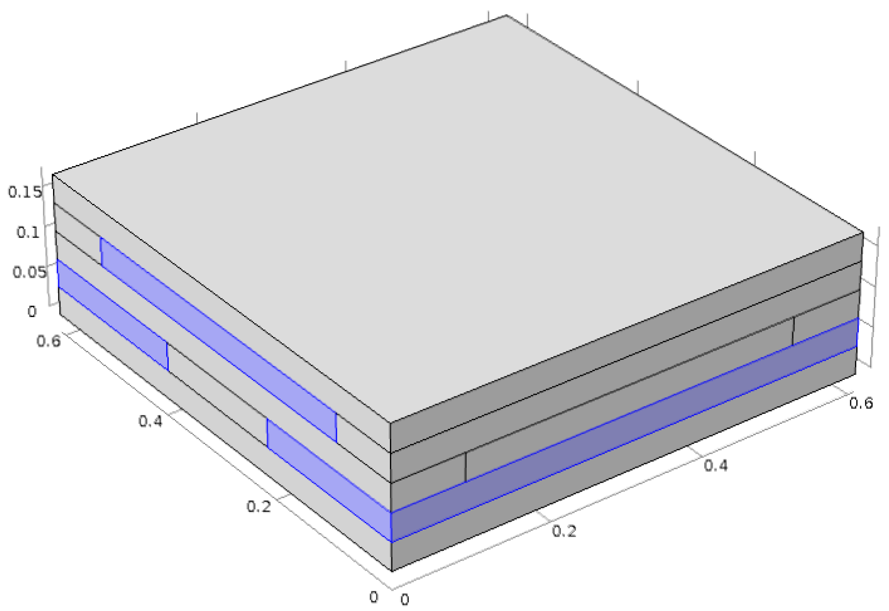
3.1. Staggered Insulation in Two Lamellae of CLT
An insulated CLT assembly was created by replacing some pieces of wood in two layers of a CLT assembly with insulation (
Figure 1). Both layers had the same percentage of insulation in the total area.
The assembly is a five-ply CLT with the layers listed in
Table 1.
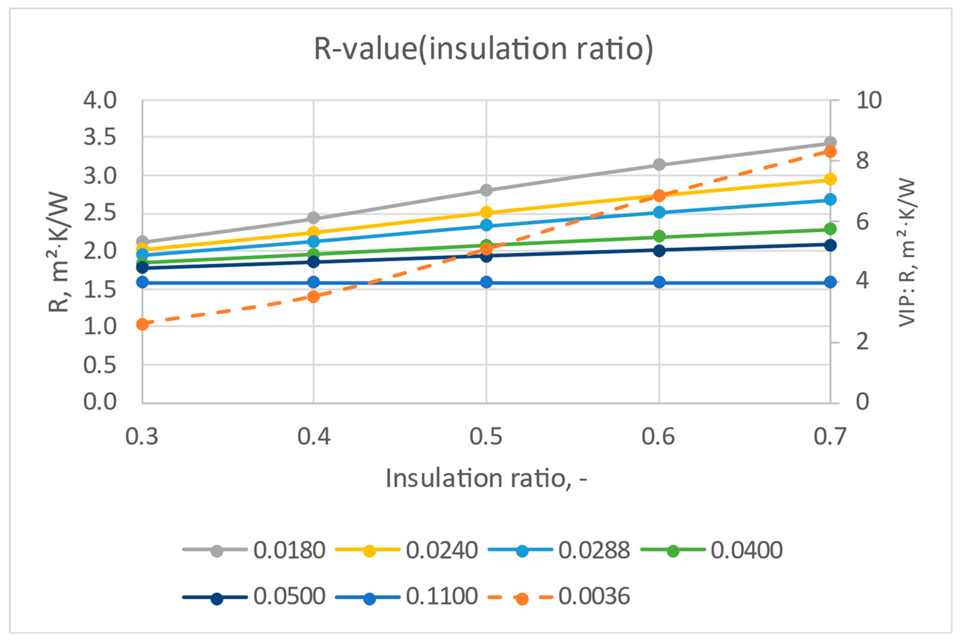
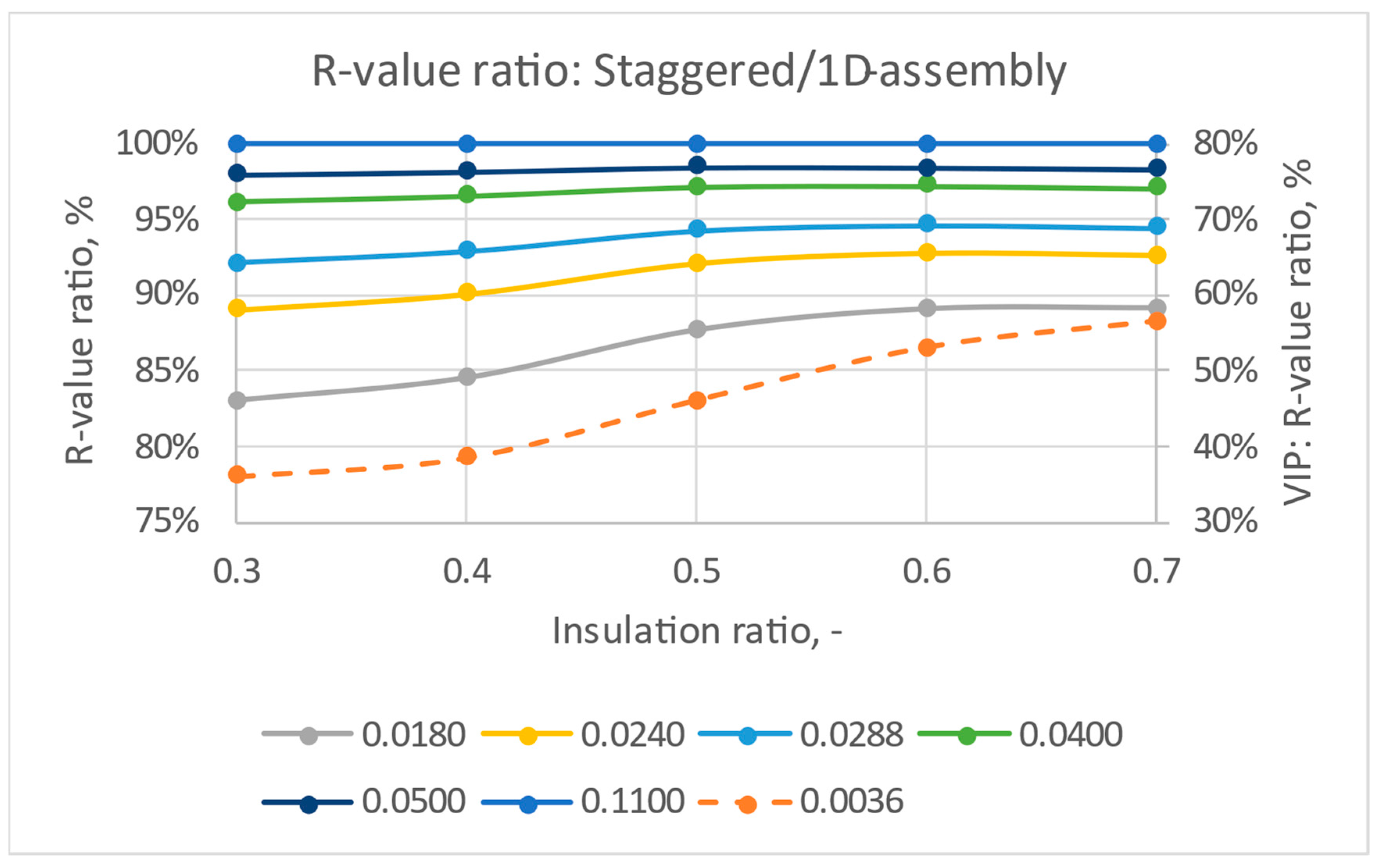
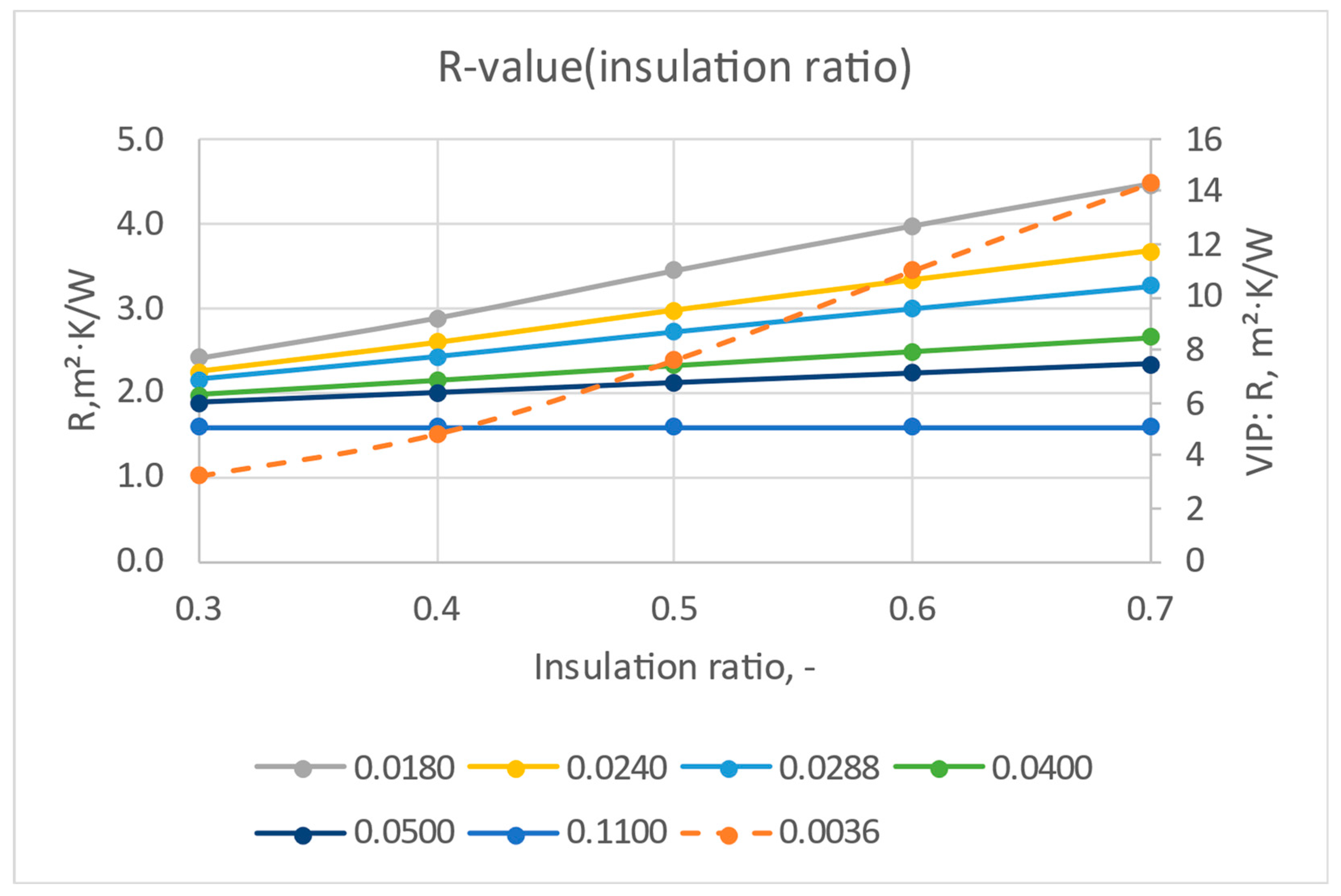
The resulting effective R-values as a function of insulation’s R-value and area coverage are shown in
Table 2. The insulation ratio is the same for each partially insulated layer (2 and 4).
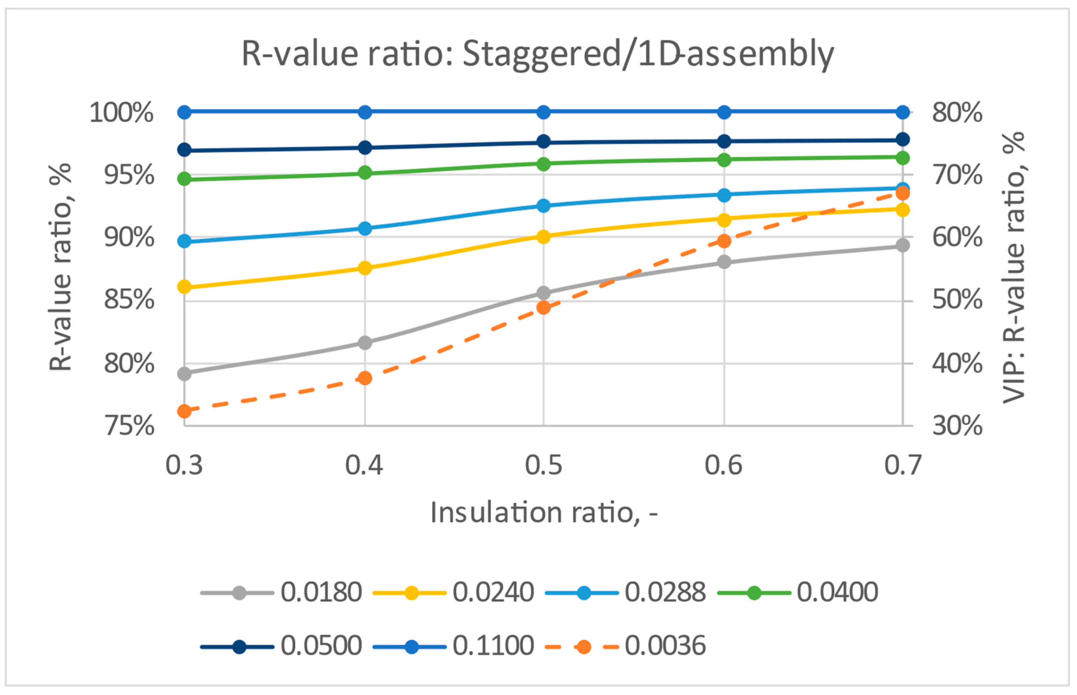
Figure 2 and
Figure 3 demonstrate that the overall R-value of the partially insulated CLT panel depends linearly on the insulation ratio in the two-layer staggered system. The impact of thermal bridging between the insulation layers is less than 12% when the insulation’s thermal conductivity is higher or equal to 0.018 W/m·K. The thermal bypasses in the system with vacuum insulation, 0.0036 W/m·K, reduce the overall R-value to half that of a system with continuous insulation when the insulation ratio is 0.3 and the volume of the insulation material is the same. The higher the insulation ratio, the smaller the impact of thermal bridging on the overall R-value.
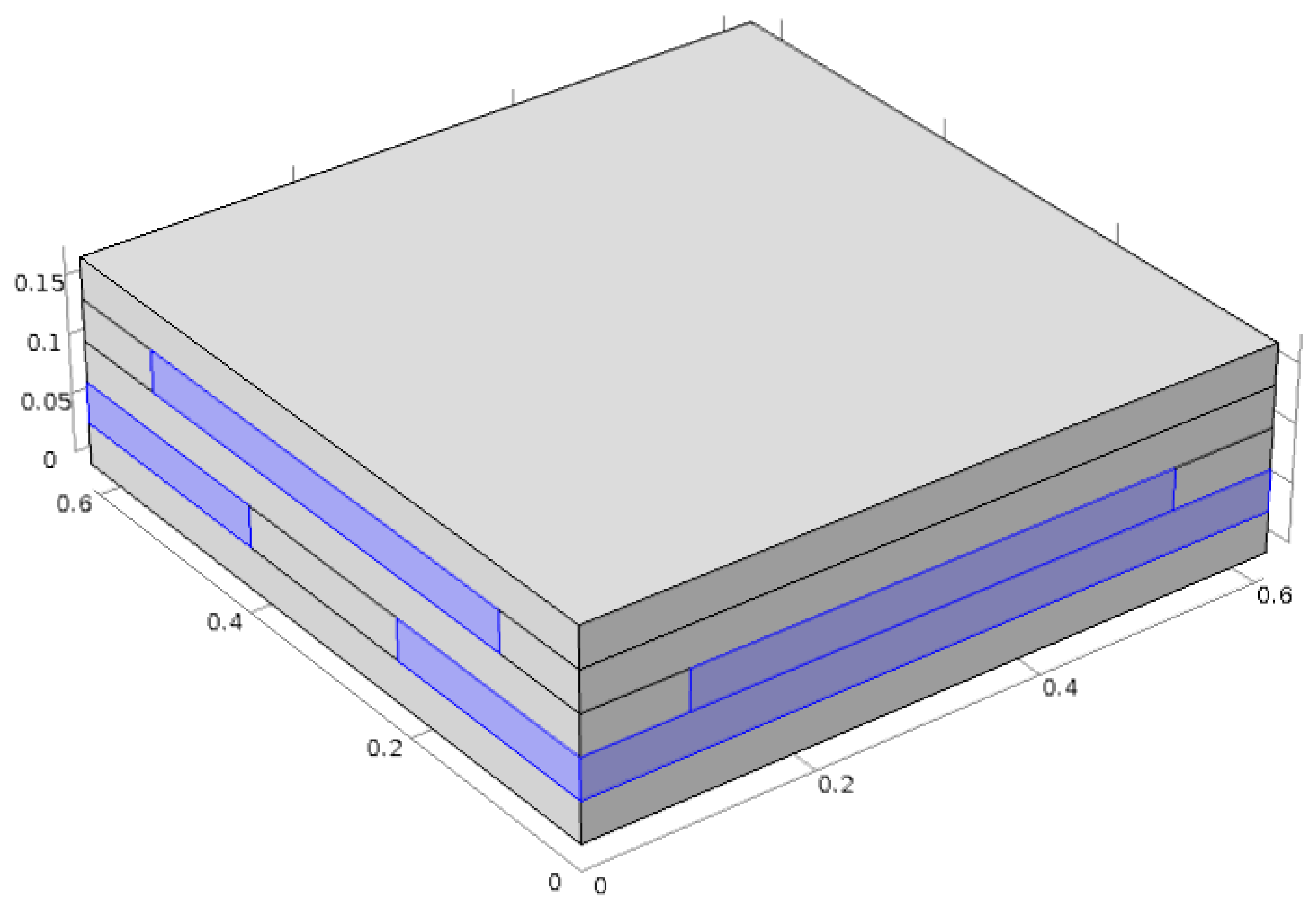
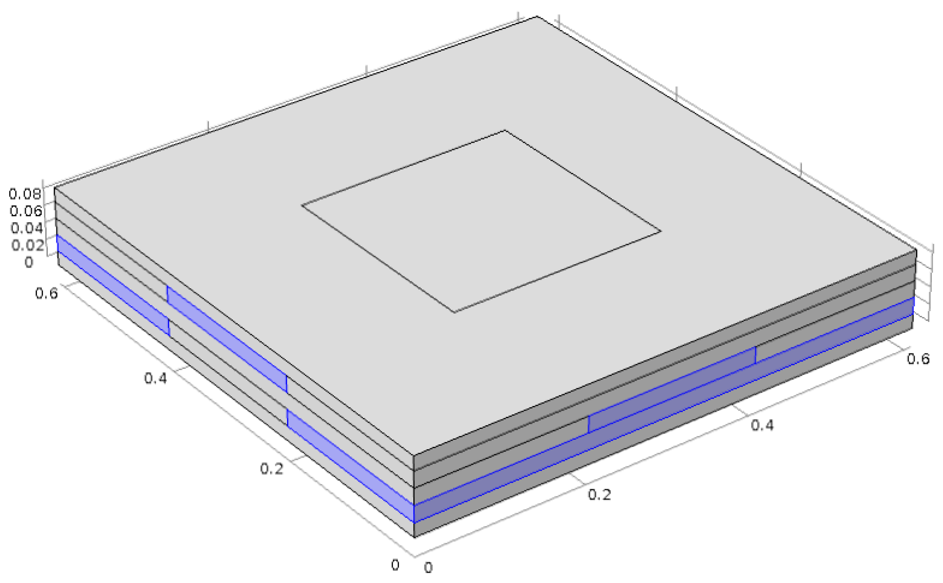
3.2. Staggered Insulation in Three Lamellae of CLT
The insulated CLT system with insulation in two lamellas of CLT was further improved by adding insulation in the third lamellae (
Figure 4). This layer runs perpendicular to the other two layers with insulation. All three layers had the same percentage of insulation in the total area.
The assembly is a five-ply CLT with the lamellae listed in
Table 3.
The resulting effective R-values as a function of the insulation’s R-value and area coverage are shown in
Table 4. The insulation ratio is the same for each partially insulated layer (2, 3, and 4).
Figure 5 and
Figure 6 demonstrate that the overall R-value of the partially insulated CLT panel depends linearly on the insulation ratio in the two-layer staggered system.
In a two-layer insulated system, the impact of thermal bridging between the insulation layers is less than 17% when the insulation’s thermal conductivity is equal to or higher than 0.018 W/m·K. The thermal bypasses in the system with vacuum insulation, 0.0036 W/m·K, reduce the overall R-value by 64% of that of a system with continuous insulation when the insulation ratio is 0.3 and the volume of the insulation material is the same. Comparing these results to the three-layer insulation system, we notice that the impact of thermal bridges is higher in the three-layer system, up to 21% with k = 0.018 W/m·K insulation and 68% with k = 0.0036 W/m·K. The higher the insulation ratio, the smaller the impact of thermal bridging on the overall R-value.
3.3. Comparing the Two- and Three-Layer Staggered Insulation CLTs
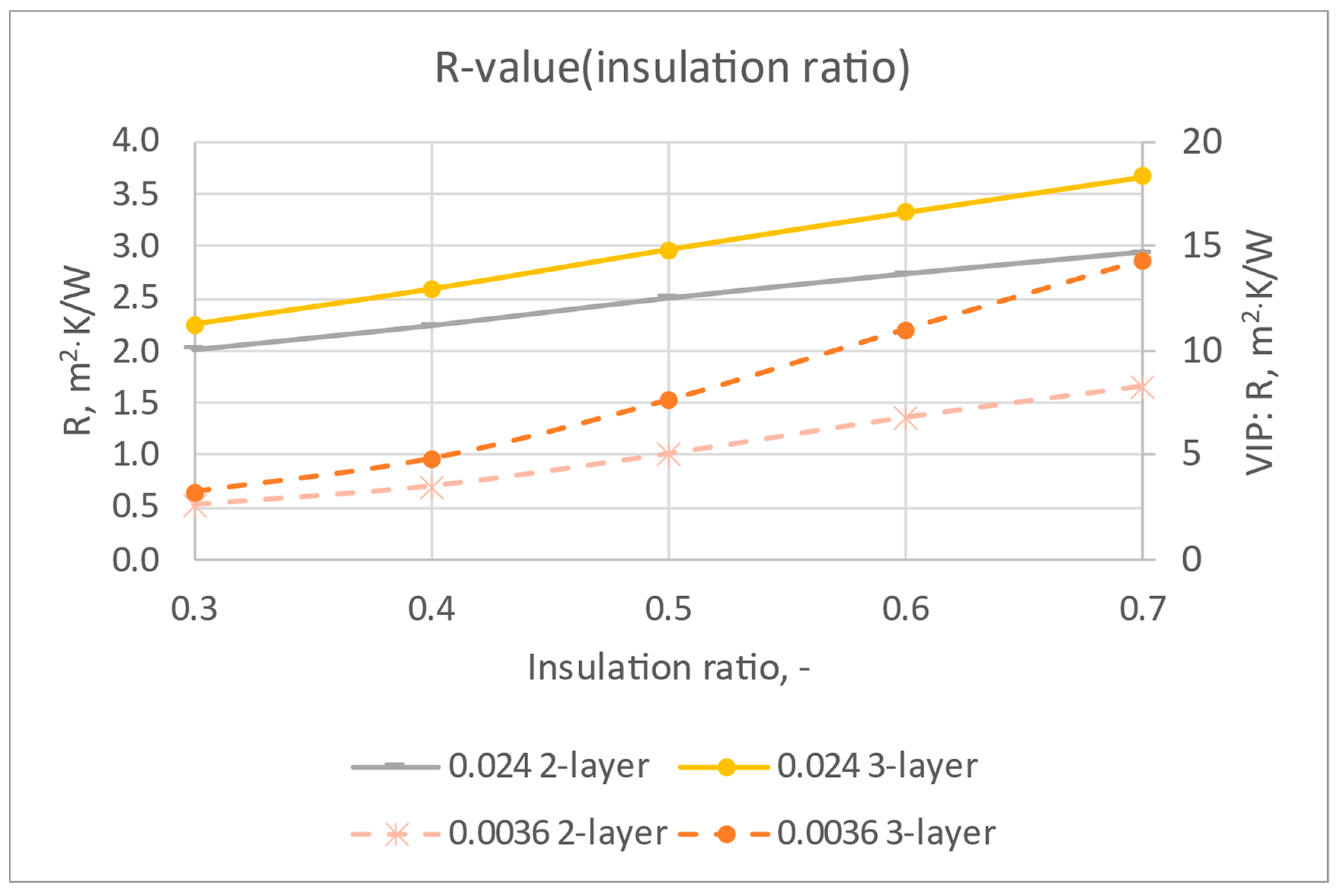
Figure 7 compares the two- and three-layer staggered insulated systems with thermal conductivity values of 0.0036 and 0.024 for the insulation. The three-layer staggered system provides a better R-value than the two-layer system with the same insulation ratio. However, the three-layer insulation system uses more insulation at the same ratio.
Table 5 shows the volume percentage of insulation when the insulation is placed in two or three layers of the CLT. Comparing the two systems at the same volume of insulation used, we can take, for example, an insulation ratio of 0.5 for the two-layer system and 0.33 for the three-layer system. In this case, both systems have one full layer of insulation out of five in the CLT. The two-layer system with R-40 per inch insulation (k = 0.0036 W/m·K) achieves an R-value of 5.1 m
2K/W, whereas the three-layer system achieves only 3.8 m
2/K/W. Therefore, the arrangement in the two-layer system is more efficient in recovering the R-value of a continuous insulation layer.
3.4. Validating Simulations with an Experimental Test
Simulations can provide theoretical values that are not necessarily replicated in real assemblies due to imperfections such as gaps between components. To validate that the simulations mimic reality, we tested one assembly with insulation in three lamellae of a five-ply CLT in a heat flow meter apparatus for a sample size of 610 mm × 610 mm. The assembly had three solid 203 mm wide wood layers of 16.7 mm thick on top and bottom. Out of the three 19.1 mm middle layers, the top and middle layers had 33% insulation in a staggered fashion (insulation ratio = 0.33) (
Figure 8). The bottom 19.1 mm layer has 2/3 insulation of the total area. The total thickness of the assembly was 90.5 mm.
The insulation’s thermal conductivity was measured in the heat flow meter and was found to be 0.033 W/m·K. The thermal conductivity of the wood was not measured but assumed to be 0.11 W/m·K. The materials and assembly were tested using a FOX 600 heat flow meter with an absolute thermal conductivity accuracy of ±1% and reproducibility of ±0.5%. The heat flow meter measures the heat flow in the center of the surfaces in an area of 254 mm × 254 mm (
Figure 8). The tested and simulated steady-state results are shown in
Table 6 for a temperature difference of 22.2 K at an average temperature of 23.9 °C. The difference between the simulated and tested results is small, less than 2%, indicating that the simulations provide accurate predictions.
3.5. Dynamic Calculations
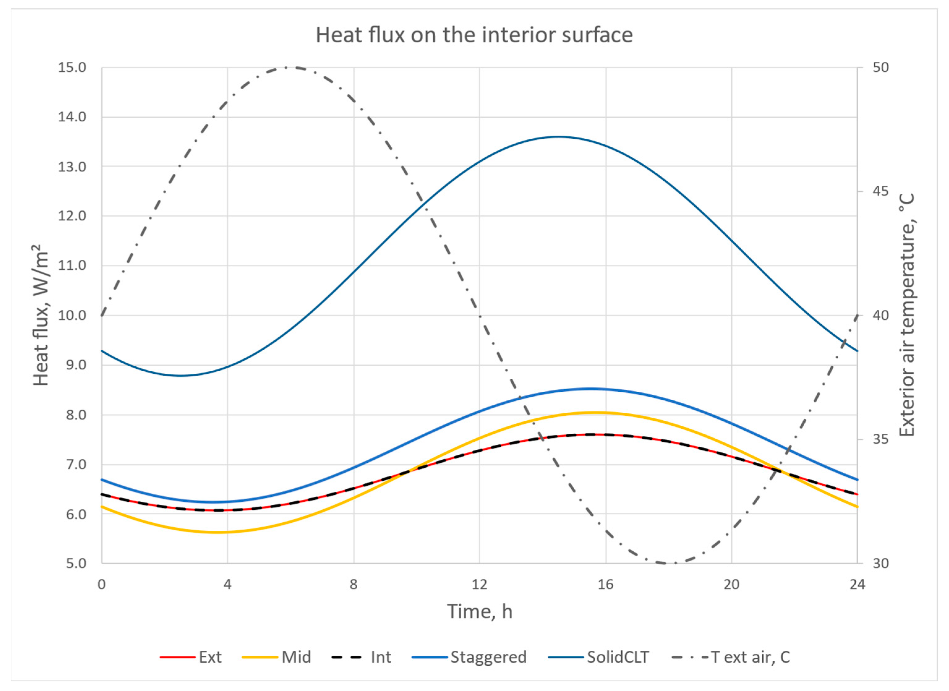
The thermal mass inherent in construction materials facilitates the absorption and storage of heat, adapting to fluctuating environmental conditions. The integration of heat capacity and thermal conductivity modulates the heat transfer rate through the material, thereby attenuating the intensity of peak thermal fluxes. The effect of thermal mass is well characterized in homogeneous material layers. The insulated CLT panels have staggered internal layers, and the dynamic performance is not as easy to estimate without advanced modeling. We simulated the transient response of the uninsulated and insulated CLT panels of the same thickness to show the impact of the insulation on the time delay and magnitude of the heat flux on the interior side when the panel was exposed to sine wave temperature on the exterior side. The sine wave had a 24 h cycle, which could be expected in natural weather exposure in buildings. The exterior and interior surface had a convection heat transfer coefficient of 10 W/m2K.
The simulations were conducted for the staggered two-layer insulation system with an insulation ratio of 0.5 and a thermal conductivity of insulation 0.024 W/m·K. Five systems were simulated with the same overall thickness of 175 mm:
Solid CLT panel
Staggered two-layer insulated CLT panel
CLT panel with continuous insulation on the exterior side
CLT panel with continuous insulation in the middle of the panel
CLT panel with continuous insulation on the interior side
Figure 9 shows how the insulation layers in the CLT panel lower the heat flux through the panel while still providing the same long time delay for the peak (~12 h). Shifting the peak heat flux from the daytime to night reduces energy use during peak demand hours, typically in the afternoon and evening hours for cooling climates.
3.6. Targeted Thermal Performance
The integration of insulation within Cross-Laminated Timber (CLT) panels represents a significant advancement in construction technology. It aligns with rigorous building codes for thermal performance without necessitating additional insulation applications on-site. Our study evaluates the compatibility of these innovative hybrid CLT panels with the 2021 International Residential Code (IRC) [
10], focusing on the mandated insulation R-value and U-value requirements across diverse International Energy Conservation Code (IECC) climate zones (
Table 7).
According to the IRC, walls possessing a thermal mass exceeding 123 kJ/m2·K are classified as mass walls within the thermal envelope of a building. The IECC standards for commercial buildings set this threshold at 103 kJ/m2·K for materials weighing under 1900 kg/m3. Our analysis indicates that 175 mm thick CLT panels, comprised of solid wood, have a thermal mass of 164 kJ/m2·K, qualifying them as mass walls. Notably, embedding insulation up to 25% by volume within these panels does not affect their classification as mass walls in residential constructions. However, this percentage might vary depending on the wood used in the CLT panels.
From a thermal performance standpoint, a 175 mm thick uninsulated CLT panel, with a thermal conductivity of 0.11 W/m·K, achieves an R-value of 1.6 m2·K/W. This results in a U-value of 0.63 W/m2·K, meeting the IECC requirements for climate zones 0 to 2. Thus, the superior thermal efficiency of wood is underscored.
Further analysis of insulated CLT configurations, such as a two-layer staggered arrangement with 20% insulation volume of k = 0.024 W/m·K insulation, revealed an R-value of 2.5 m2·K/W. A similar three-layer configuration yielded an R-value of 2.4 m2·K/W, with the two-layer system’s improved thermal efficiency mainly due to reduced thermal bridging. The U-value for the two-layer insulated system was calculated at 0.40 W/m2·K, demonstrating that hybrid CLT panels can meet building code requirements across a broad range of climate zones.
Including additional layers, such as gypsum boards and exterior sidings, along with surface resistances, can further enhance thermal resistance by at least R-0.35 m2·K/W, leading to a U-value of 0.34 W/m2·K. This is adequate for meeting the thermal requirements of climate zone 6 for mass walls and zones 0 to 3 for frame walls. Increasing the insulation ratio to 28% of the total volume, with an insulation thermal conductivity of 0.024 W/m·K, results in a U-value of approximately 0.30 W/m2·K, fulfilling the insulation criteria for all climate zones for mass walls.
While traditional rigid foam insulations provide thermal conductivity down to 0.024 W/m·K, advanced materials like vacuum insulation panels offer higher insulation properties. However, these materials require protection from mechanical damage to maintain their insulating effectiveness. Embedding such panels within CLT structures can safeguard them, ensuring the durability and performance of the insulation.
3.7. Impact of CLT on Peak Demand
The impact of thermal mass on peak demand and annual energy use for heating and cooling was predicted by using a whole-building simulation model, EnergyPlus [
12]. EnergyPlus
TM is a comprehensive building energy simulation program developed with contributions from several national labs and organizations under the funding and guidance of the U.S. Department of Energy (DOE). Since its inception in 1997, EnergyPlus has been subject to continuous updates and enhancements, reflecting the latest in building energy modeling research and technology.
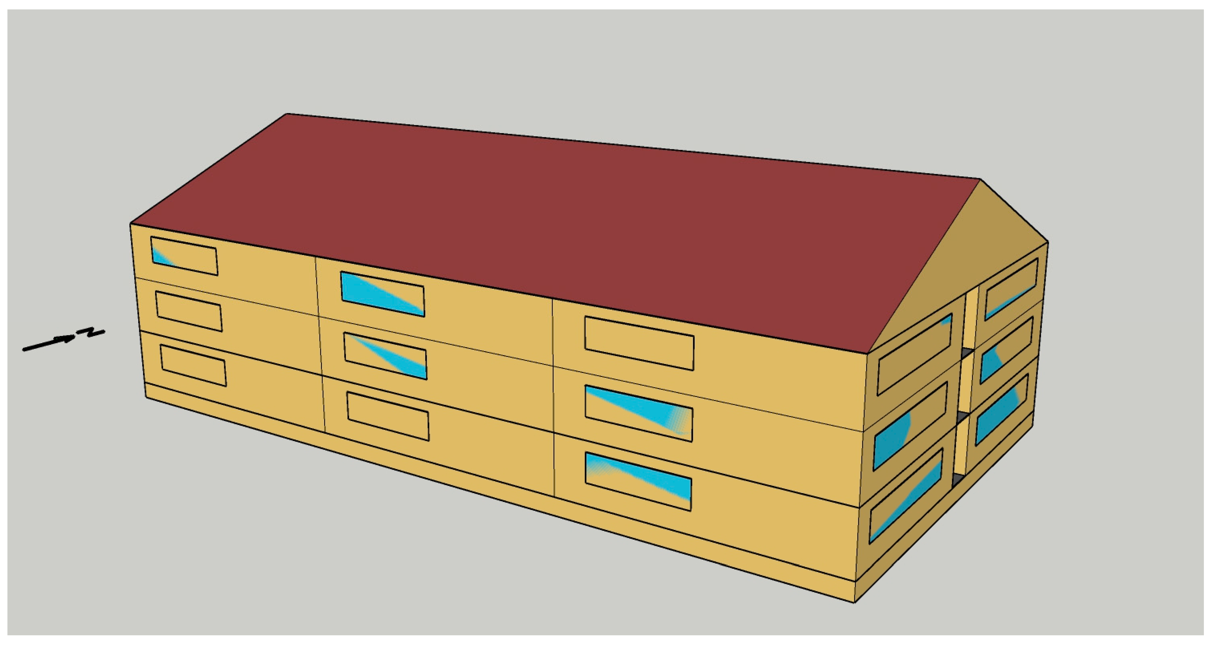
DOE has created prototype building models for EnergyPlus for different types of buildings [
13]. For the simulations, we chose a three-story multifamily building (
Figure 10) with a heat pump for heating and cooling in Knoxville, TN. Of the total building area, 3623 m
2, 2007 m
2 is conditioned. The base model has features, such as the exterior wall construction, per the International Energy Conservation Code 2021. The base model with the lightweight wall assembly was modified by replacing the wood-frame structure with an insulated CLT assembly while maintaining the U-value of 0.271 W/m
2·K. No other changes were made to the model inputs except changing the location and weather file to Knoxville, TN. Thus, all the equipment, internal loads, occupancy schedules, and set points were preserved. The wall layers and their properties are listed in
Table 8. Note that EnergyPlus treats wall assemblies as one-dimensional components. The two-dimensional staggered system must be simplified to a three-layer setup with half the thickness of CLT on each side of an insulation layer. Columns LW and CLT show which layers are part of the lightweight and CLT wall assemblies.
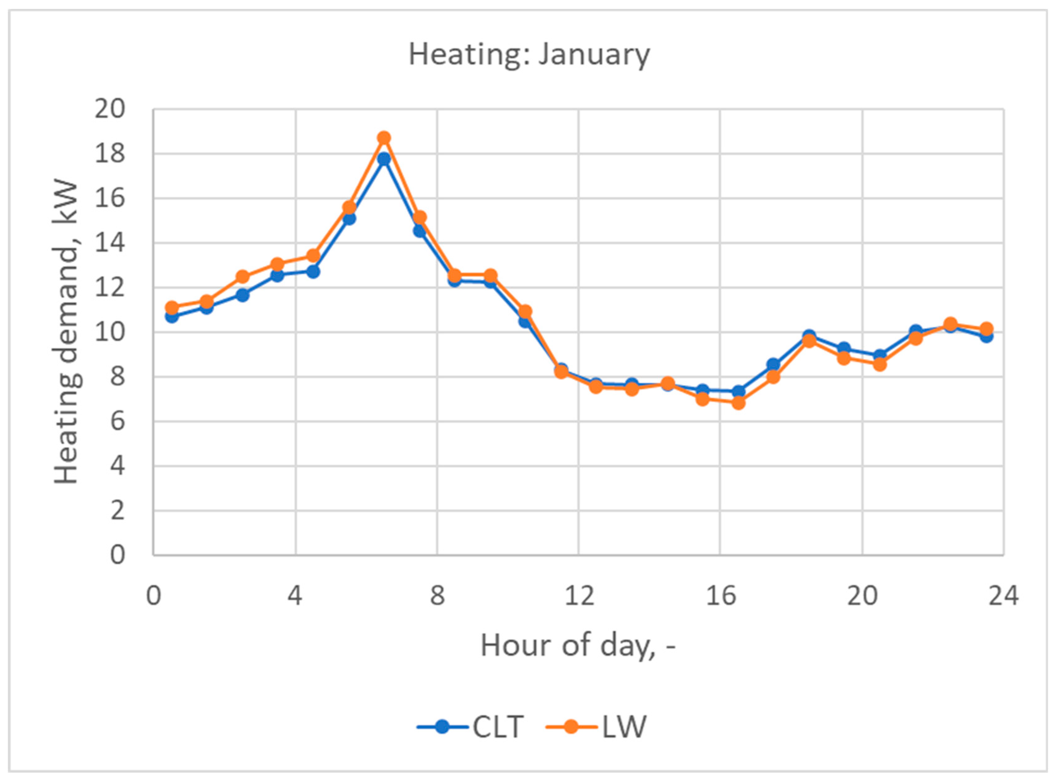
The annual energy consumption for heating and cooling exhibited a reduction of 2.4% when employing the Cross-Laminated Timber (CLT) wall assembly, compared to the lightweight construction. Specifically, the building outfitted with CLT walls recorded an electricity usage of 53,215 kWh, whereas the structure with lightweight walls accounted for 54,500 kWh.
Figure 11 delineates the diurnal heating demand, identifying a morning peak where the CLT wall assembly facilitates a 5.2% decrease in heating requirements compared to its lightweight counterpart.
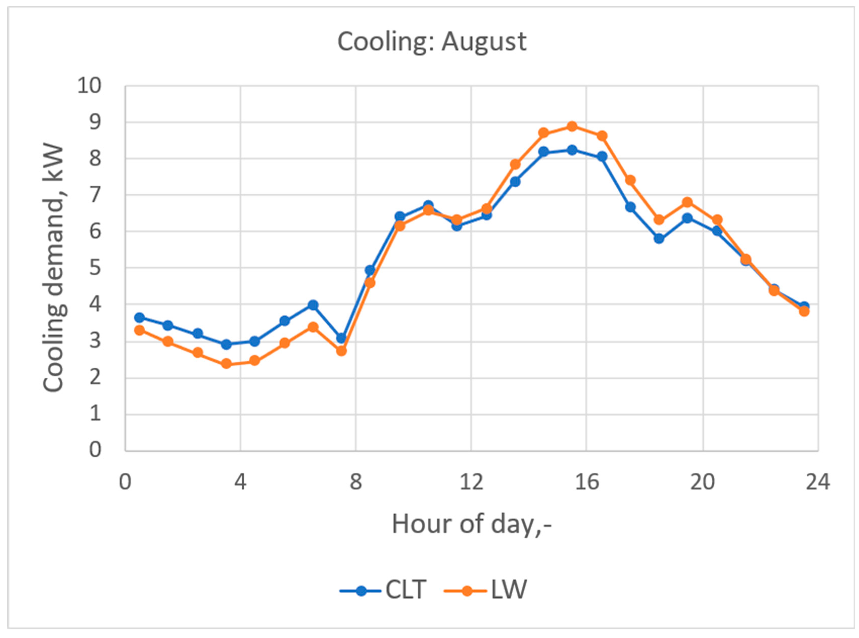
Figure 12 illustrates the cooling demand patterns during August, pinpointing the peak cooling load. Notably, in August, the CLT wall assembly demonstrated a 7.1% reduction in peak cooling demand relative to the lightweight construction, underscoring its efficiency in thermal management.
The results show that the CLT wall assembly dampens the heat flows through the exterior wall and flattens the heating and cooling demand between night and day. For example, the CLT building has higher cooling demand at night but lower in the afternoon and evening.
3.8. Carbon Benefits of the Insulated CLT
Considering sequestered carbon in the embodied carbon calculations for mass timber and Cross-Laminated Timber (CLT) is a topic of ongoing debate within the sustainability and construction communities. Trees absorb carbon dioxide from the atmosphere as they grow, known as carbon sequestration. When trees are harvested and used in building materials like mass timber and CLT, that carbon is effectively stored in the built environment, potentially for decades or centuries. Including sequestered carbon in embodied carbon calculations acknowledges this benefit and can show mass timber and CLT as more sustainable options than materials like steel or concrete, which have higher embodied carbon and do not sequester carbon.
Accounting for sequestered carbon adds complexity to embodied carbon calculations due to the need to consider factors like the source of the timber, forest management practices, and the likelihood of the carbon being released back into the atmosphere at the end of the product’s life (e.g., through decay or combustion). These factors can vary widely and introduce uncertainty into the calculations. There is a risk that the same sequestered carbon could be counted multiple times in different products or accounting systems, leading to overestimating the actual carbon benefits. For example, if the carbon sequestered by a forest is counted in national carbon inventories, counting it again in the embodied carbon of timber products could lead to double counting. The carbon stored in mass timber and CLT will eventually be released back into the atmosphere when the material decomposes or is burned at the end of its life. Unless there are guarantees that the material will be reused, recycled, or permanently sequestered, including sequestered carbon in embodied calculations could give a misleading impression of the material’s long-term environmental impact.
The impact of internally insulated CLT on carbon released to the atmosphere is multifaceted, involving considerations of operational and embodied carbon, carbon sequestration, construction efficiency, and end-of-life scenarios. The overall impact will depend on factors such as the choice of insulation materials, the energy sources used during the building’s operation, and the practices for managing the building materials at the end of their life. Substituting some wood layers with insulation material will alter the embodied carbon of the CLT panels. The net effect on embodied carbon will depend on the type of insulation material used. If the insulation is made from materials with low embodied carbon, the overall embodied carbon of the insulated CLT panels may be lower than standard CLT panels. Conversely, if the insulation material has high embodied carbon (e.g., certain foams or plastics), it could increase the total embodied carbon of the panels. The pre-installation of water-resistive barriers and the integration of insulation can streamline the construction process, reducing the time and potentially the energy required on-site. This efficiency can lead to lower carbon emissions associated with construction activities.
Improved energy efficiency in buildings can reduce the overall energy demand, potentially leading to decreased carbon emissions at a larger scale within the energy grid, assuming a mix of fossil fuels and renewable energy sources.
On a negative note, non-wood materials (like insulation and water-resistive barriers) within the CLT panels could complicate recycling or reuse at the end of the building’s life, potentially leading to higher carbon emissions associated with waste processing or disposal. However, the impact could be mitigated if these materials are selected for recyclability or systems are in place for recovery.


