

Experimental Study to Determine the Development of Axial Stiffness of Wood Screws with Increasing Load Cycles

Abstract
:1. Introduction and State of Knowledge
2. Research Objectives
3. Experimental Investigation
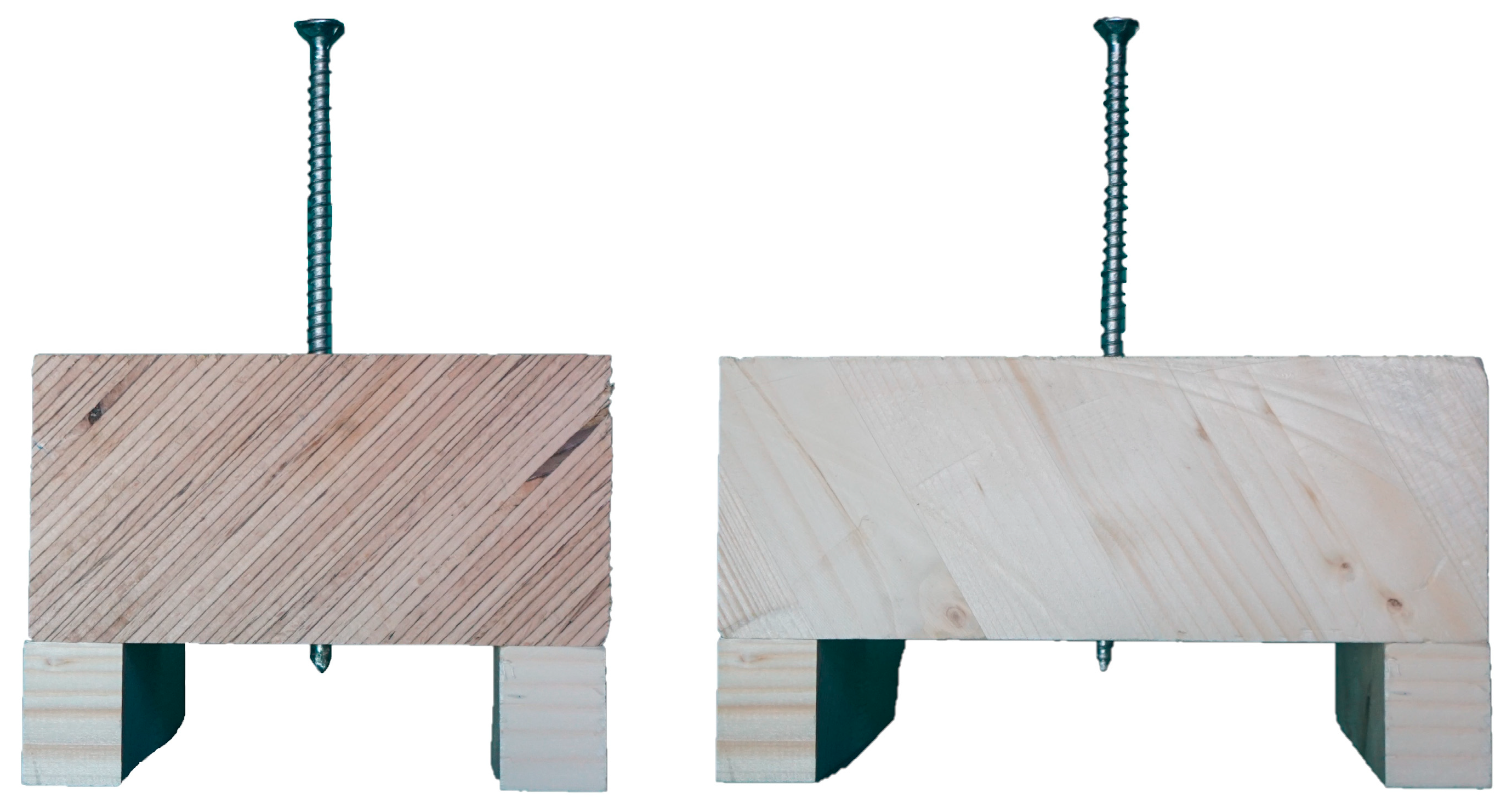
3.1. Material
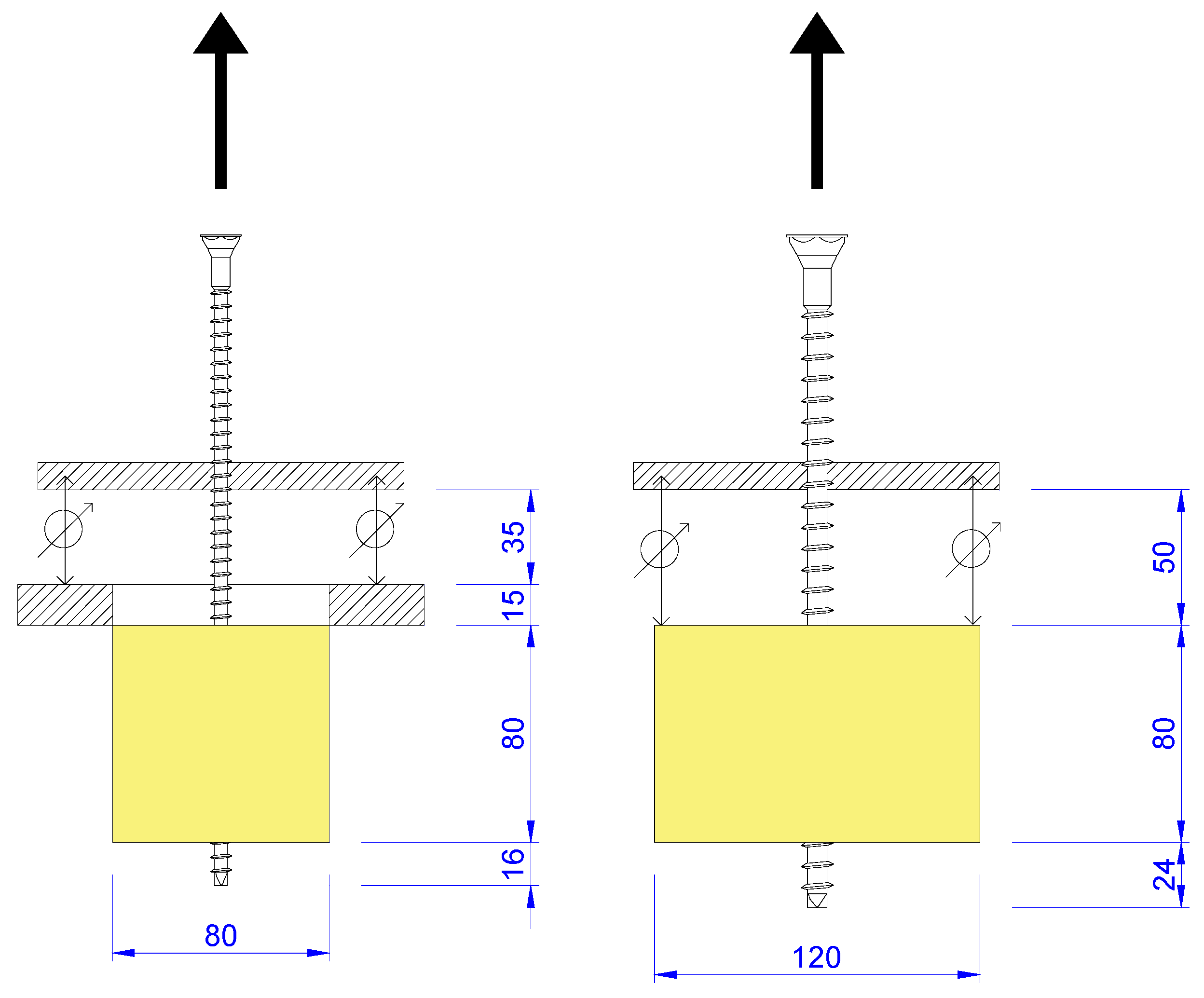
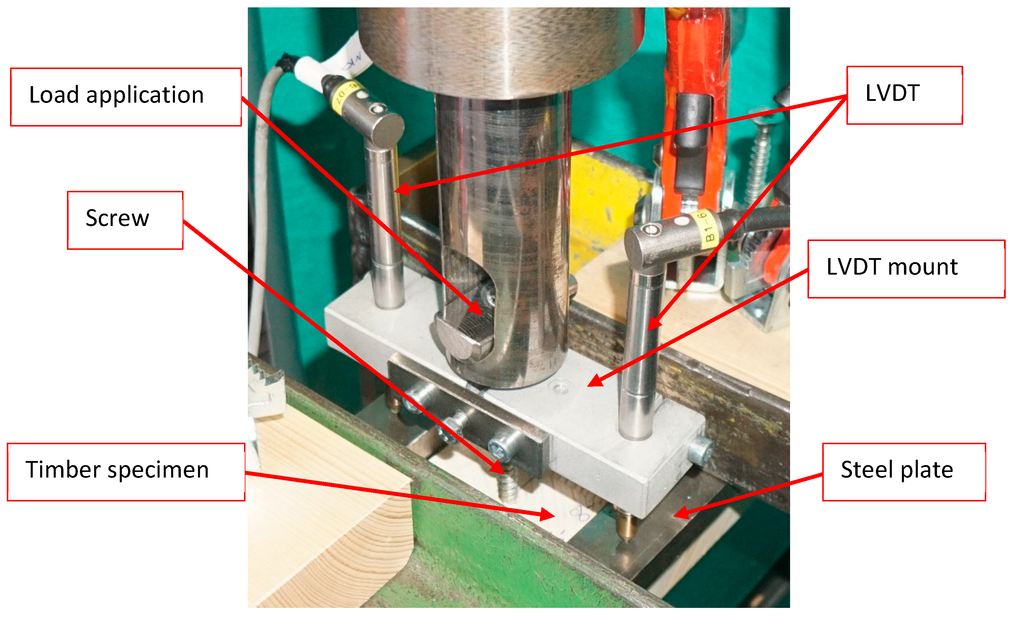
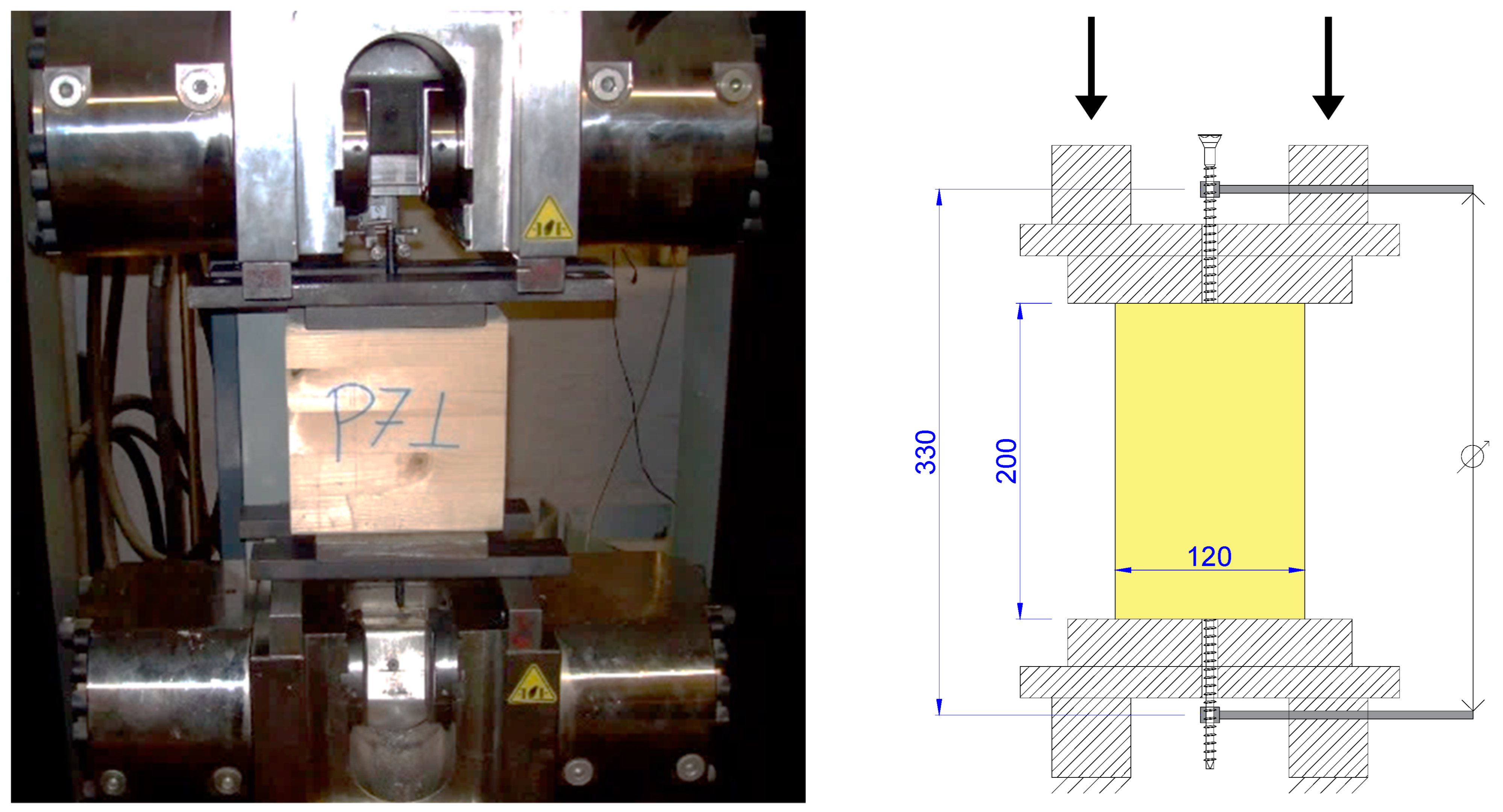
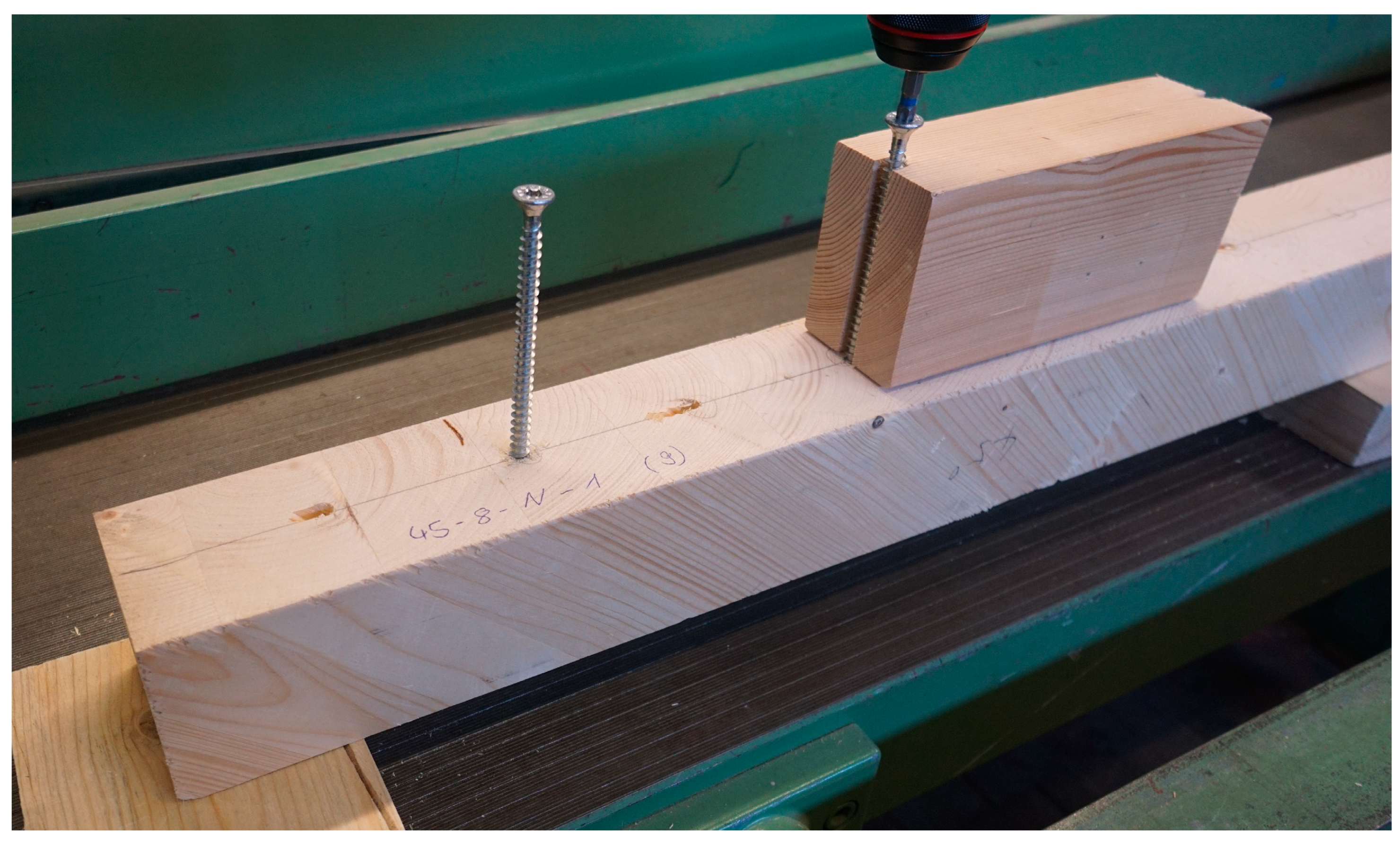
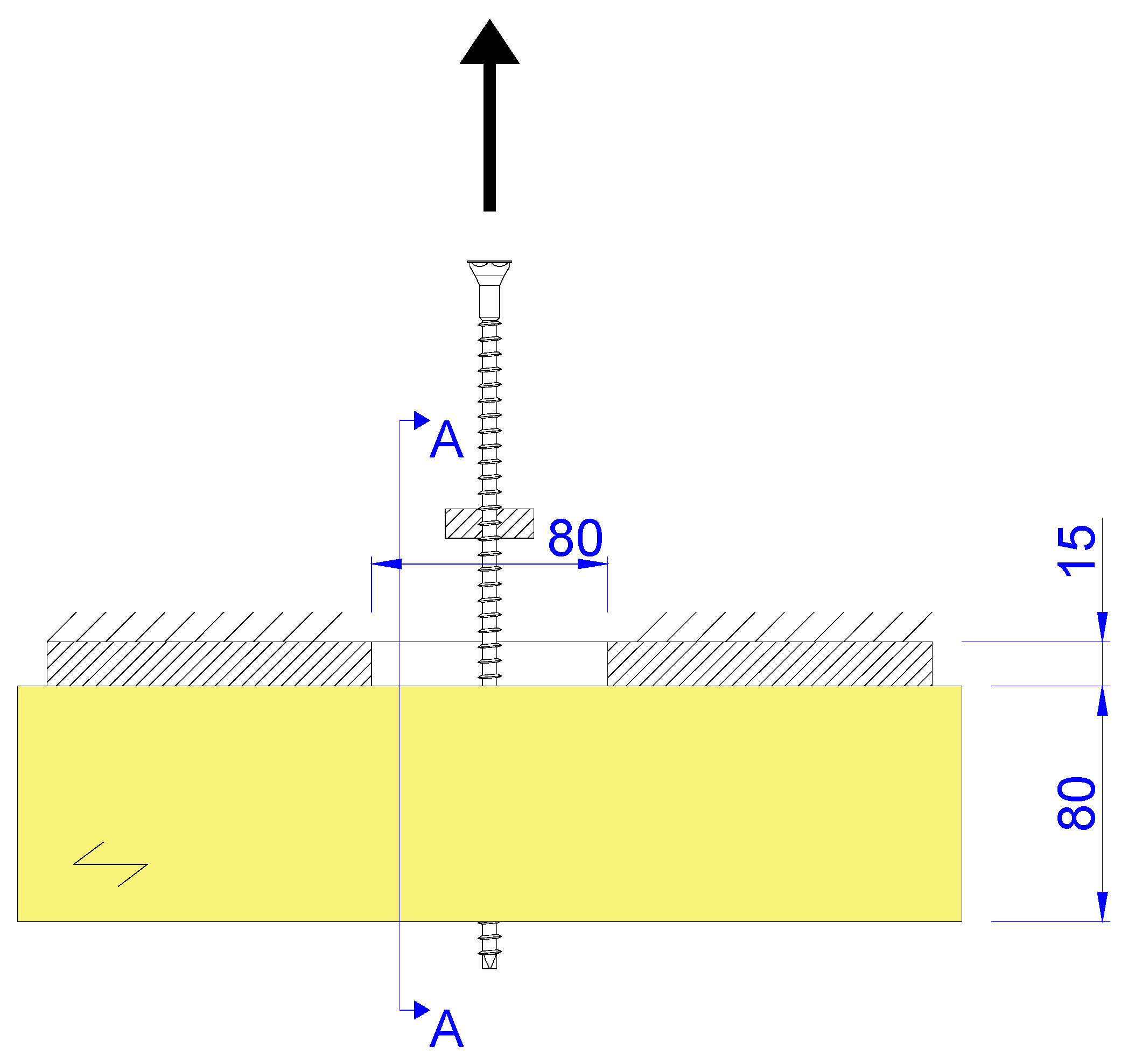
3.2. Test Setup
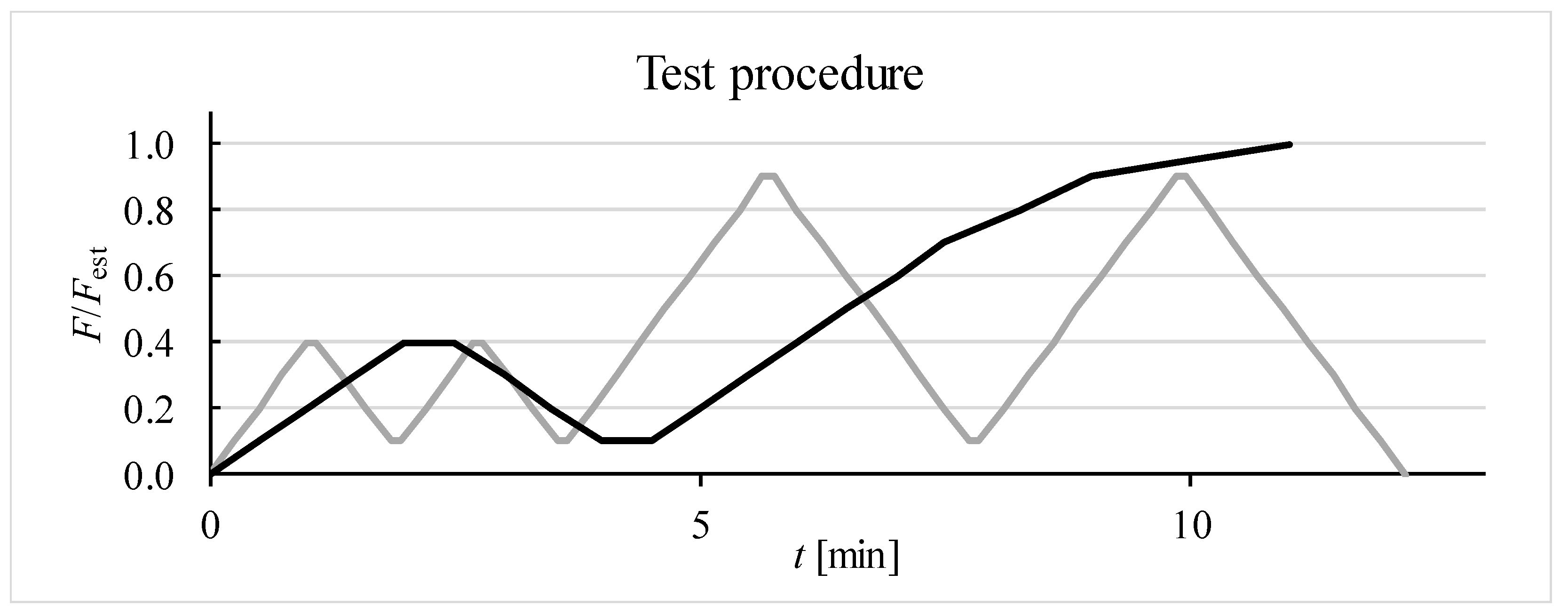
3.3. Test Procedure
3.4. Test Observations
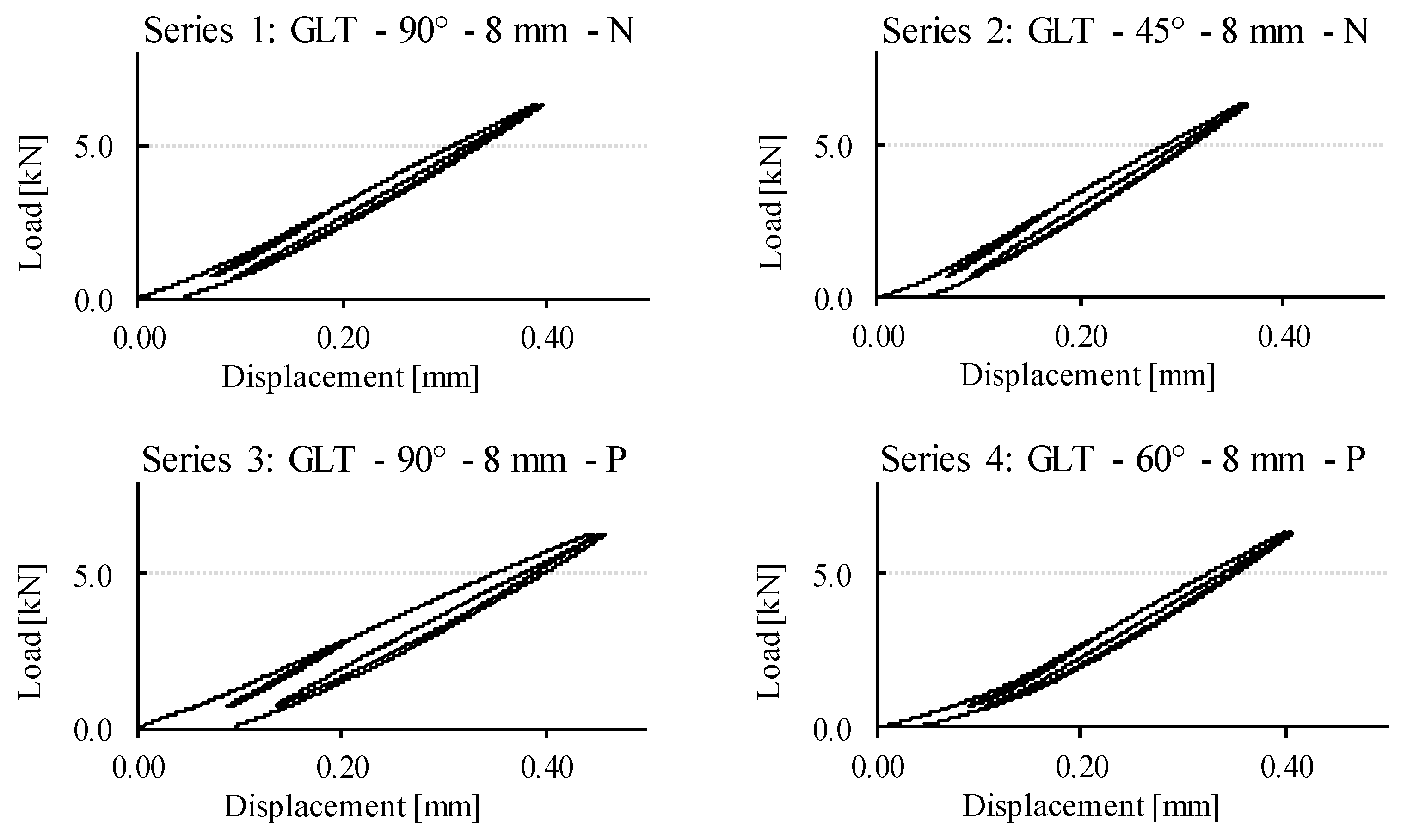
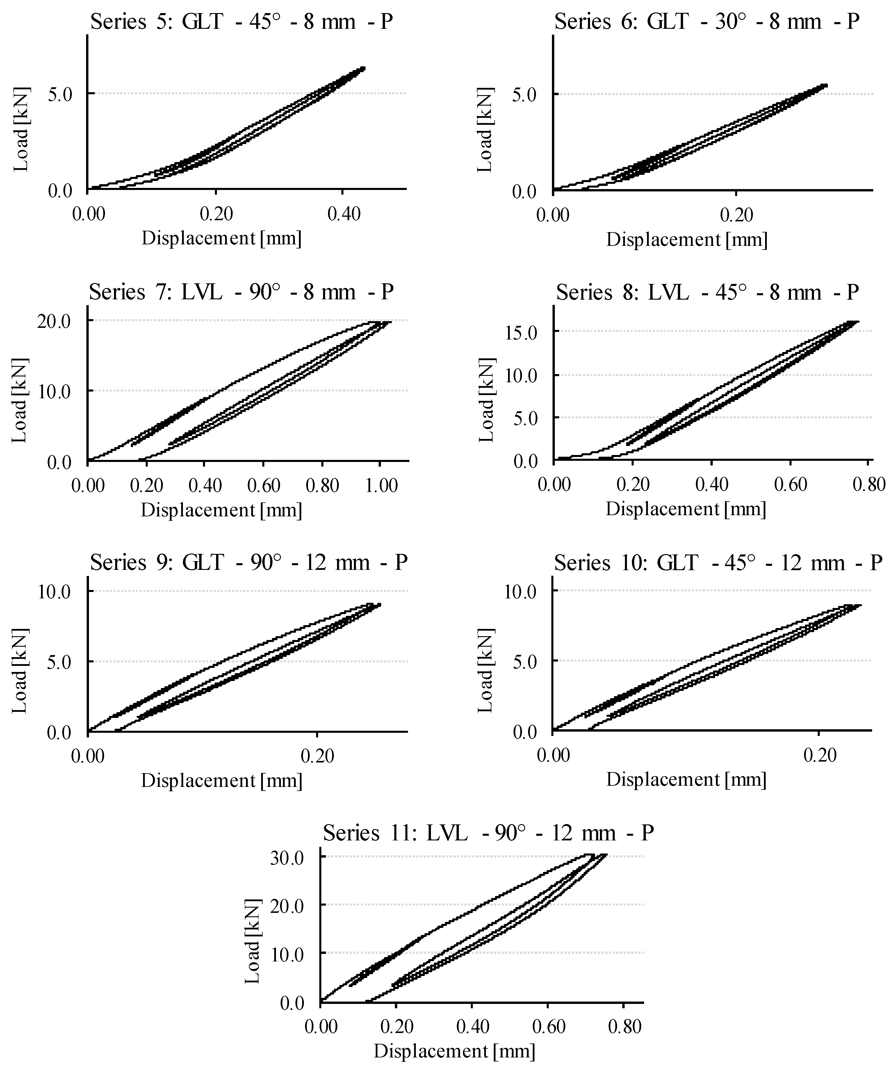
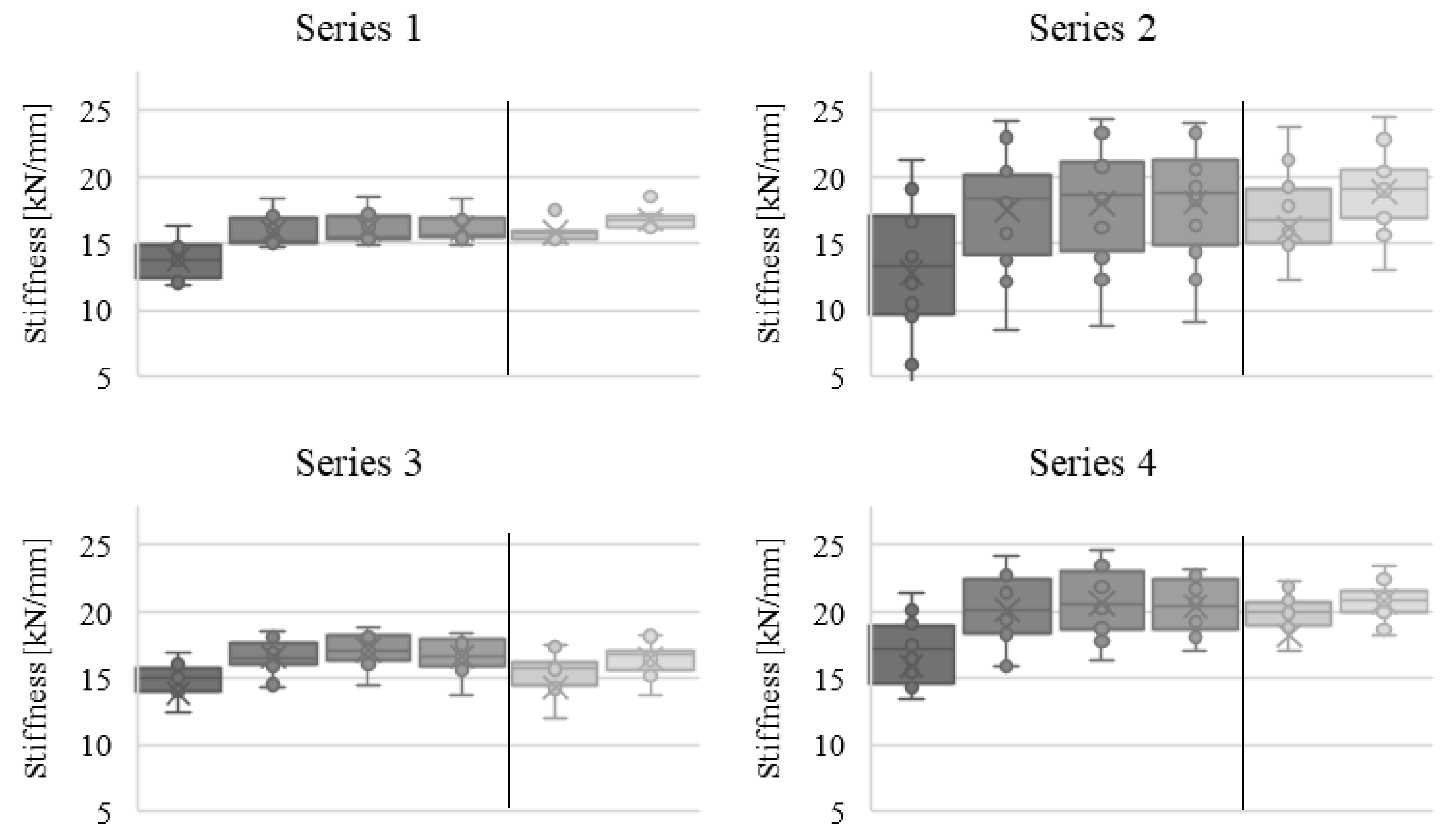
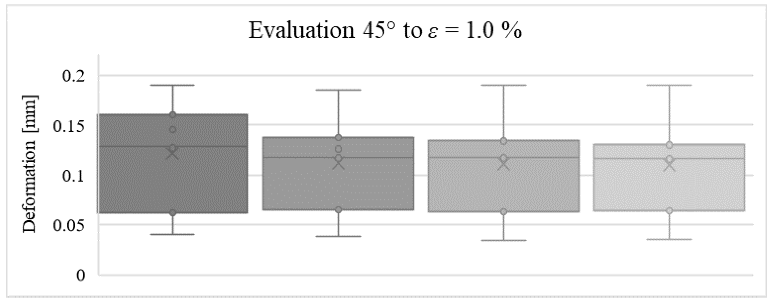
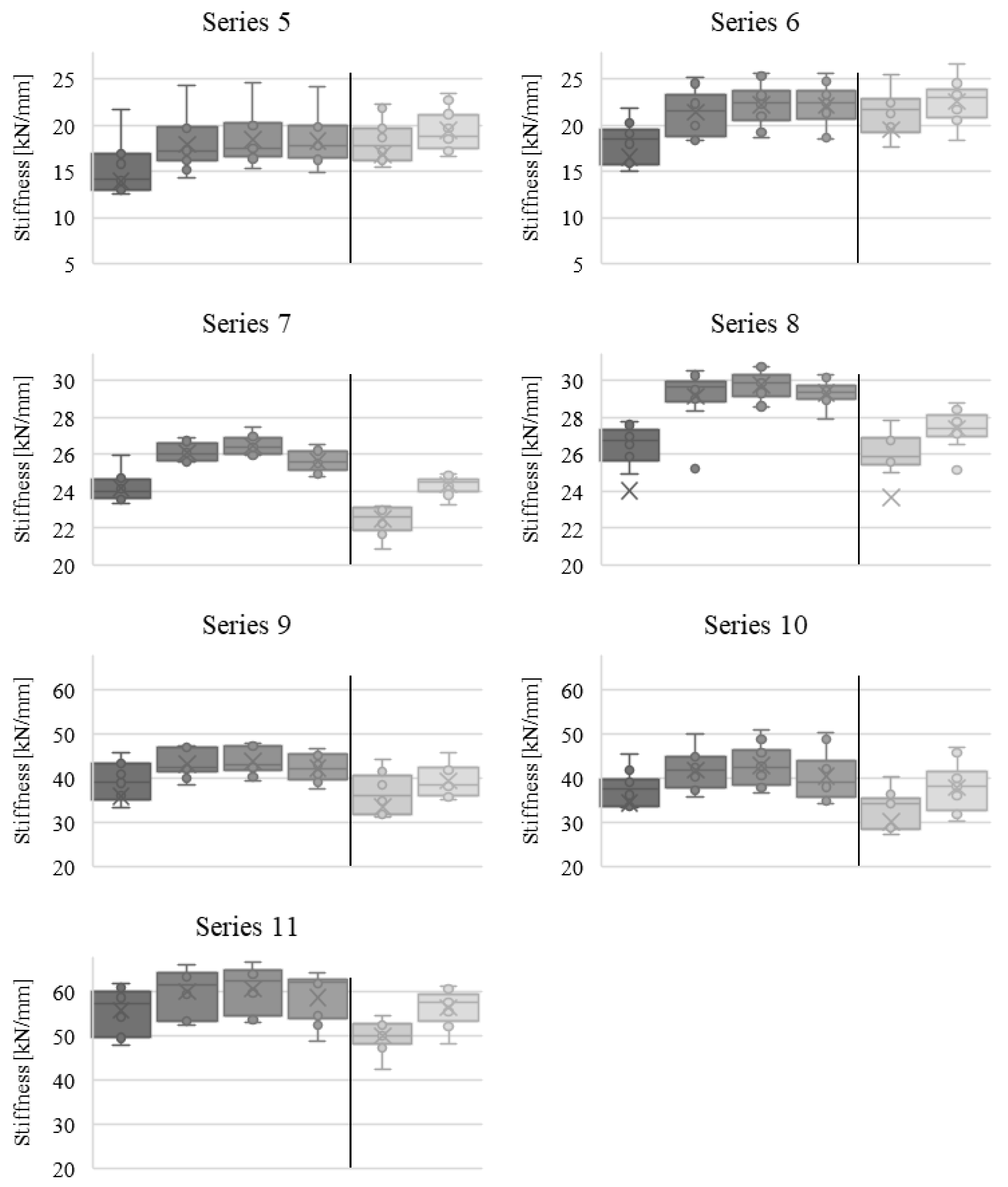
3.5. Results and Analysis
3.6. Discussion of Test Results
3.6.1. Influence of Pre-Drilling
3.6.2. Influence of Timber Product
3.6.3. Influence of Insertion Angle
3.6.4. Influence of Screw Diameter
3.6.5. Influence of Load Level
4. Comparison with Existing Experimental Results
5. Conclusions
- The tests carried out show that repeated loading will increase the axial stiffness of an axially loaded screw in timber products as long as the load is within the elastic range of the connection. The average increase is around 11% from first to second loading.
- Possible influencing factors such as screw geometry, axis-to-grain angle, pre-drilling, or type of timber product have no significant influence on the development of axial stiffness under cyclic loading.
- Only the load level has a significant influence. If plastic deformation occurs during high loading, the axial stiffness will be reduced by up to −12%.
- It can therefore be assumed that the axial stiffness generally increases when reloading in the elastic range. This is also consistent with the tests previously carried out by Dietsch [14]. As the same effect was observed despite fundamentally different test setups, it is evident that an increase in axial stiffness is a basic phenomenon that is independent of the applied test setup.
- This specific behaviour of connections has positive implications for practical design situations. Cyclic loading does not lead to significantly higher deformations in connections with axially loaded screws. Therefore, it can be assumed that the development of axial stiffness does not have a negative influence on long-term deformations.
- Loads leading to plastic deformation would cause a significant reduction in axial stiffness. However, with the exception of accidental design situations, it is unlikely that such high loads will occur in structures in practice. Even after loading close to the characteristic load capacity, the reduction in axial stiffness is only slightly below the level at initial loading.
- It should be pointed out that increased connection stiffness could lead to a possible increase in undesired secondary stresses. However, this effect is mitigated by the specific material behaviour of timber product such as the relaxation behaviour.
Author Contributions
Funding
Data Availability Statement
Conflicts of Interest
References
- Ringhofer, A. Axially Loaded Self-Tapping Screws in Solid Timber and Laminated Timber Products. Ph.D. Thesis, Graz University of Technology, Graz, Austria, 2017. [Google Scholar]
- Jockwer, R.; Steiger, R.; Frangi, A. Design model for inclined screws under varying load to grain angles. In Proceedings of the International Network on Timber Engineering Research INTER, Meeting 47, Bath, UK, 1–4 September 2014. [Google Scholar]
- Blaß, H.J.; Bejtka, I.; Uibel, T. Tragfähigkeit von Verbindungen mit Selbstbohrenden Holzschrauben mit Vollgewinde; Universitätsverlag Karlsruhe: Karlsruhe, Germany, 2006. [Google Scholar]
- Blaß, H.J.; Steige, Y. Steifigkeit Axial Beanspruchter Vollgewindeschrauben; KIT Scientific Publishing: Karlsruhe, Germany, 2016. [Google Scholar]
- Tomasi, R.; Crosatti, A.; Piazza, M. Theoretical and experimental analysis of timber-to-timber joints connected with inclined screws. Constr. Build. Mater. 2010, 24, 1560–1571. [Google Scholar] [CrossRef]
- Brandner, R.; Ringhofer, A.; Reichinger, T. Performance of axially-loaded self-tapping screws in hardwood: Properties and design. Eng. Struct. 2019, 188, 677–699. [Google Scholar] [CrossRef]
- Ringhofer, A.; Brandner, R.; Schickhofer, G. A Universal Approach for Withdrawal Properties of Self-Tapping Screws in Solid Timber and Laminated Timber Products. In Proceedings of the International Network on Timber Engineering Research INTER, Meeting 48, Šibenik, Croatia, 24–27 August 2015. [Google Scholar]
- Azinovic, B.; Frese, M. FE modelling of timber connections with inclined and cross-wise arranged screws—Few findings on testing the shear stiffness. In Proceedings of the International Network on Timber Engineering Research INTER, Meeting 53, Online, 17–19 August 2020. [Google Scholar]
- De Santis, Y.; Fragiacomo, M. Slip modulus formulas for timber-to-timber inclined screw connections. Comparison with other simplified models. In Proceedings of the International Network on Timber Engineering Research INTER, Meeting 54, Online, 16–19 August 2021. [Google Scholar]
- Girhammar, U.A.; Jacquier, N.; Källsner, B. Stiffness model for inclined screws in shear-tension mode in timber-to-timber joints. Eng. Struct. 2017, 136, 580–595. [Google Scholar] [CrossRef]
- Ringhofer, A.; Burtschner, M.; Sieder, R.; Gstettner, M. Self-tapping Timber Screws Subjected to Combined Axial and Lateral Loading. In Proceedings of the International Network on Timber Engineering Research INTER, Meeting 54, Online, 16–19 August 2021. [Google Scholar]
- Hu, W.; Liu, Y.; Konukcu, A.C. Study on Withdrawal Load Resistance of Screw in Wood-Based Materials: Experimental and Numerical. Wood Mater. Sci. Eng. 2023, 18, 334–343. [Google Scholar] [CrossRef]
- Piazza, M.; Polastri, A.; Tomasi, R. Ductility of timber joints under static and cyclic loads. Proc. Inst. Civ. Eng. Struct. Build. 2011, 164, 79–90. [Google Scholar] [CrossRef]
- Dietsch, P. Einsatz und Berechnung von Schubverstärkungen für Brettschichtholz. Ph.D. Thesis, Technische Universität München, Munich, Germany, 2012. [Google Scholar]
- ETA-11/0190; Würth Self-Tapping Screws for Use in Timber Constructions. Adolf Würth GmbH & Co. KG: Künzelsau, Germany; DIBt: Berlin, Germany, 2018.
- DIN EN 14592:2012-07; Holzbauwerke—Stiftförmige Verbindungsmittel—Anforderungen. Beuth Verlag: Berlin, Germany, 2012.
- DIN EN 26891:1991-07; Holzbauwerke—Verbindungen mit Mechanischen Verbindungsmitteln—Allgemeine Grundsätze für die Ermittlung der Tragfähigkeit und des Verformungsverhaltens. Beuth Verlag: Berlin, Germany, 1991.


| Series | Number of Tests | Timber Product | Mean Density | COV | Screw Diameter | Load-to-Grain Angle | Pre-Drilling | Fest |
|---|---|---|---|---|---|---|---|---|
| [kg/m3] | [%] | [mm] | [°] | [kN] | ||||
| 1 | 9 | GLT spruce | 449 | 0.0 | 8 | 90 | no | 7.5 |
| 2 | 12 | GLT spruce | 457 | 2.7 | 8 | 45 | no | 7.5 |
| 3 | 13 | GLT spruce | 389 | 1.0 | 8 | 90 | yes | 7.5 |
| 4 | 12 | GLT spruce | 487 | 0.0 | 8 | 60 | yes | 7.5 |
| 5 | 11 | GLT spruce | 451 | 0.0 | 8 | 45 | yes | 7.5 |
| 6 | 10 | GLT spruce | 462 | 4.8 | 8 | 30 | yes | 5.8 |
| 7 | 12 | Beech-LVL | 813 | 0.0 | 8 | 90 | yes | 22.4 |
| 8 | 10 | Beech-LVL | 795 | 0.0 | 8 | 45 | yes | 17.9 |
| 9 | 10 | GLT spruce | 456 | 3.6 | 12 | 90 | yes | 10.3 |
| 10 | 10 | GLT spruce | 419 | 1.1 | 12 | 45 | yes | 10.3 |
| 11 | 10 | Beech-LVL | 805 | 1.1 | 12 | 90 | yes | 33.6 |
| Series | 1. Loading 0–40% | 1. Loading 10–40% | 2. Loading 10–40% | 3. Loading 10–40% | 4. Loading 10–40% | ||||||||
|---|---|---|---|---|---|---|---|---|---|---|---|---|---|
| [kN/mm] | COV [%] | [kN/mm] | COV [%] | [kN/ mm] | COV [%] | Change [%] | [kN/mm] | COV [%] | Change [%] | [kN/mm] | COV [%] | Change [%] | |
| 1 | 10.9 | 19.2 | 13.8 | 10.5 | 15.9 | 7.2 | +15.7 | 16.1 | 7.0 | +17.2 | 16.1 | 6.5 | +17.1 |
| 2 | 11.4 | 35.3 | 14.3 | 30.1 | 17.7 | 24.6 | +23.5 | 18.0 | 24.2 | +25.6 | 18.0 | 23.5 | +25.9 |
| 3 | 13.2 | 10.2 | 15.0 | 7.6 | 16.9 | 6.9 | +12.5 | 17.1 | 6.8 | +14.2 | 16.6 | 7.5 | +10.9 |
| 4 | 14.4 | 21.9 | 17.2 | 13.0 | 20.2 | 11.5 | +17.6 | 20.7 | 11.7 | +20.0 | 20.3 | 10.1 | +18.1 |
| 5 | 13.5 | 17.3 | 15.2 | 16.4 | 18.2 | 13.7 | +19.3 | 18.4 | 13.6 | +21.1 | 18.3 | 13.7 | +20.3 |
| 6 | 14.8 | 18.3 | 18.4 | 10.7 | 21.8 | 9.8 | +18.7 | 22.3 | 9.9 | +21.4 | 22.1 | 9.9 | +20.1 |
| 7 | 21.6 | 4.1 | 24.2 | 2.9 | 26.1 | 1.8 | +8.0 | 26.5 | 1.9 | +9.4 | 25.6 | 2.1 | +6.0 |
| 8 | 19.9 | 16.2 | 26.5 | 3.5 | 29.5 | 2.3 | +11.1 | 29.8 | 2.2 | +12.3 | 29.3 | 2.3 | +10.3 |
| 9 | 40.9 | 7.7 | 40.1 | 9.0 | 43.4 | 6.6 | +8.2 | 43.8 | 6.4 | +9.2 | 42.0 | 7.2 | +4.6 |
| 10 | 39.6 | 11.7 | 38.9 | 10.2 | 42.3 | 10.6 | +8.7 | 42.9 | 10.4 | +10.3 | 40.3 | 12.1 | +3.6 |
| 11 | 56.0 | 7.2 | 55.7 | 8.7 | 60.1 | 8.3 | +7.7 | 60.7 | 8.0 | +8.9 | 58.6 | 8.9 | +5.2 |
| Mean | -- | 15.4 | -- | 11.2 | -- | 9.4 | +13.7 | -- | 9.3 | +15.4 | -- | 9.4 | +12.9 |
| Series | 3. Loading 10–90% | 4. Loading 10–90% | ||||
|---|---|---|---|---|---|---|
| [kN/mm] | COV [%] | Change [%] | [kN/mm] | COV [%] | Change [%] | |
| 1 | 15.8 | 4.2 | +14.8 | 16.8 | 4.2 | +22.0 |
| 2 | 17.8 | 16.6 | +23.9 | 19.0 | 15.9 | +32.3 |
| 3 | 15.5 | 8.8 | +3.6 | 16.6 | 7.0 | +10.6 |
| 4 | 19.8 | 7.1 | +14.8 | 20.8 | 6.5 | +20.7 |
| 5 | 18.4 | 11.2 | +20.8 | 19.5 | 10.4 | +28.2 |
| 6 | 21.6 | 9.3 | +17.6 | 22.7 | 9.4 | +23.4 |
| 7 | 22.5 | 3.1 | −7.0 | 24.4 | 1.9 | +0.7 |
| 8 | 26.2 | 3.3 | −1.3 | 27.5 | 2.5 | +3.8 |
| 9 | 37.0 | 10.6 | −7.7 | 39.6 | 8.4 | −1.3 |
| 10 | 34.2 | 12.0 | −12.1 | 38.2 | 14.0 | −1.8 |
| 11 | 50.0 | 6.8 | −10.3 | 56.4 | 6.7 | +1.1 |
| Mean | -- | 8.5 | +5.2 | -- | 7.9 | +12.7 |
Disclaimer/Publisher’s Note: The statements, opinions and data contained in all publications are solely those of the individual author(s) and contributor(s) and not of MDPI and/or the editor(s). MDPI and/or the editor(s) disclaim responsibility for any injury to people or property resulting from any ideas, methods, instructions or products referred to in the content. |
© 2024 by the authors. Licensee MDPI, Basel, Switzerland. This article is an open access article distributed under the terms and conditions of the Creative Commons Attribution (CC BY) license (https://creativecommons.org/licenses/by/4.0/).
Share and Cite
Egner, S.; Dietsch, P. Experimental Study to Determine the Development of Axial Stiffness of Wood Screws with Increasing Load Cycles. Buildings 2024, 14, 1109. https://doi.org/10.3390/buildings14041109
Egner S, Dietsch P. Experimental Study to Determine the Development of Axial Stiffness of Wood Screws with Increasing Load Cycles. Buildings. 2024; 14(4):1109. https://doi.org/10.3390/buildings14041109
Chicago/Turabian StyleEgner, Sebastian, and Philipp Dietsch. 2024. "Experimental Study to Determine the Development of Axial Stiffness of Wood Screws with Increasing Load Cycles" Buildings 14, no. 4: 1109. https://doi.org/10.3390/buildings14041109
APA StyleEgner, S., & Dietsch, P. (2024). Experimental Study to Determine the Development of Axial Stiffness of Wood Screws with Increasing Load Cycles. Buildings, 14(4), 1109. https://doi.org/10.3390/buildings14041109