Article

A Framework for Auditing Robot-Inclusivity of Indoor Environments Based on Lighting Condition

by
Zimou Zeng
1,
Matthew S. K. Yeo
1,
Charan Satya Chandra Sairam Borusu
1,
M. A. Viraj J. Muthugala
1,*,
Michael Budig
1,
Mohan Rajesh Elara
1 and
Yixiao Wang
2
1
Engineering Product Development Pillar, Singapore University of Technology and Design, Singapore 487372, Singapore
2
School of Industrial Design, Georgia Institute of Technology, Atlanta, GA 30332, USA
*
Author to whom correspondence should be addressed.
Buildings 2024, 14(4), 1110; https://doi.org/10.3390/buildings14041110
Submission received: 29 February 2024 / Revised: 1 April 2024 / Accepted: 10 April 2024 / Published: 16 April 2024
(This article belongs to the Section Building Energy, Physics, Environment, and Systems)

Abstract

:
Mobile service robots employ vision systems to discern objects in their workspaces for navigation or object detection. The lighting conditions of the surroundings affect a robot’s ability to discern and navigate in its work environment. Robot inclusivity principles can be used to determine the suitability of a site’s lighting condition for robot performance. This paper proposes a novel framework for autonomously auditing the Robot Inclusivity Index of indoor environments based on the lighting condition (RII-lux). The framework considers the factors of light intensity and the presence of glare to define the RII-Lux of a particular location in an environment. The auditing framework is implemented on a robot to autonomously generate a heatmap visually representing the variation in RII-Lux of an environment. The applicability of the proposed framework for generating true-to-life RII-Lux heatmaps has been validated through experimental results.

1. Introduction

Over the past few years, there has been a notable increase in the use of mobile robots in indoor spaces for tasks that were previously confined to typical industrial applications [1]. Among these, robotic cleaning systems have become particularly popular, exhibiting not only efficiency but also adaptability to intricate surroundings [2]. These systems are especially renowned for their sophisticated navigation, debris detection, and cleanup capabilities. In the field of elder care, robots have become indispensable companions and providers of physical support [3]. They are transforming care, particularly by improving the standard of living for elderly people with cognitive or mobility impairments. Additionally, robotic technology has revolutionized inventory management and warehouse operations in the logistics industry through automation [4]. These robots significantly optimize logistics workflows. Lastly, in tour guiding, robots are increasingly used in museums and other cultural venues to provide engaging and educational experiences [5]. These robotic guides enhance visitor engagement and learning in such environments.
The ability of a robot to perceive its environment is a crucial component of its operation across many applications [6,7]. Robotic vision systems are critical to allow a robot to perceive its surroundings, which are increasingly important in the field of robotics [8,9]. These vision systems in robots employ a combination of cameras, sensors, and advanced algorithms to interpret their surroundings. This approach has become a fundamental aspect of contemporary robotic design.
Object detection in robotics is the process of recognizing and locating objects within the robot’s visual field, an essential function for numerous applications. The development of systems like YOLOv8, an advanced neural network model among other object detection models, is typically used for object detection. YOLOv8’s ability to process images with high speed and accuracy makes it a benchmark in robotic vision technology [10]. For example, in cleaning robots, vision systems powered by algorithms similar to YOLOv8 enable the identification of obstacles or targeted cleaning areas.
However, the effectiveness of these vision systems can be compromised by lighting conditions, with factors such as reflections, conflicting background colors, and vibrations during operation [11,12,13]. Variations in lighting can affect the system’s ability to detect and classify objects accurately. Reflections and background colors can create visual noise [14,15], leading to incorrect interpretations by the vision system. These limitations highlight the vulnerability of robots to environmental factors, potentially leading to operational failures in certain situations with regards to lighting conditions. The robustness of vision systems under varying conditions is, therefore, a critical area of research, one that continues to evolve with the development of more sophisticated technologies and algorithms [14,16].
Other advances in hazard perception and its relation to workplace lighting conditions include designing complex systems for human-following robots under varying lighting conditions [17], methods to reduce the impact of changing lighting conditions on robotic operation through advanced sensor systems [18,19], and complicated operational algorithms [20]. These methods are mostly computationally or resource-intensive, hindering robotic adoption for service tasks. Moreover, these papers discuss the difficulties of having varying lighting conditions for robots but do not provide ways to quantify and rate the work environments in terms of robot inclusivity for mobile robotic deployments.
The concept of ’Design for Robot’ (DfR) represents a burgeoning field in robotic research, aimed at creating environments more conducive to robotic operation by adapting infrastructural elements to enhance robot inclusivity [21,22]. This concept refers to optimizing environments to support the efficient functioning of robots while ensuring human requirements. DfR employs a multidisciplinary approach, integrating insights from robotics, architecture, and human-robot interaction studies, with the goal of designing spaces that are accommodating for both humans and robots [23,24,25].
Key considerations for DfR include modifying spatial layouts, surface materials, and lighting conditions, along with specific navigational aids to assist robot navigation and task execution, such as using specialized markings in hospital hallways to improve the efficiency of robots transporting supplies [26]. Additionally, DfR addresses the dynamics of human-robot interaction, which is especially vital in environments where they coexist and collaborate, like manufacturing plants or service industries. In these settings, DfR focuses on ensuring safety, efficiency, and harmony, which may involve redefining workspace layouts [27] or introducing new operational protocols [28,29] to enable seamless integration of robotic systems into the human work environment [30]. However, a notable research gap exists in assessing how environmental factors such as lighting conditions would impact robot inclusivity, and no autonomous system has been developed yet to evaluate the inclusivity of building infrastructure for robots.
This paper aims to establish a correlation between these measures and a robot’s vision system performance metrics and how the various lighting conditions would impact robotic operations. In this regard, this paper introduces a novel auditing framework, the ‘Robot-Inclusivity Index based on Lighting’ (RII-Lux), to autonomously quantify the influence of lighting conditions in an environment on robotic performance. This framework would enable better demarcation of zones with low robot inclusivity due to lighting conditions. This demarcation could prompt measures on modifying the zone’s lighting conditions to improve robot performance and mark a substantial advancement in the field of DfR. Section 2 details the factors being considered for evaluating robot inclusivity in terms of environmental lighting. Section 3 outlines the process for automating the map generation for RII-Lux, along with specifications for the audit robot used in the experiment. Section 4 discusses the experiment and validation of the RII-Lux framework. Lastly, Section 5 concludes this paper.

2. Evaluating Robot-Inclusivity

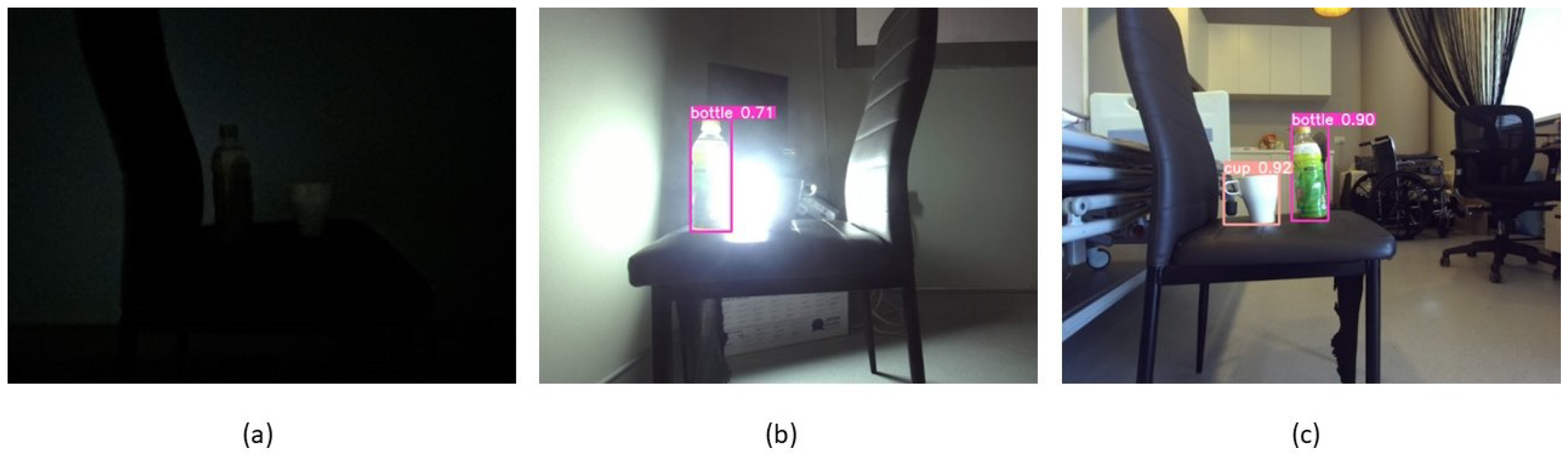
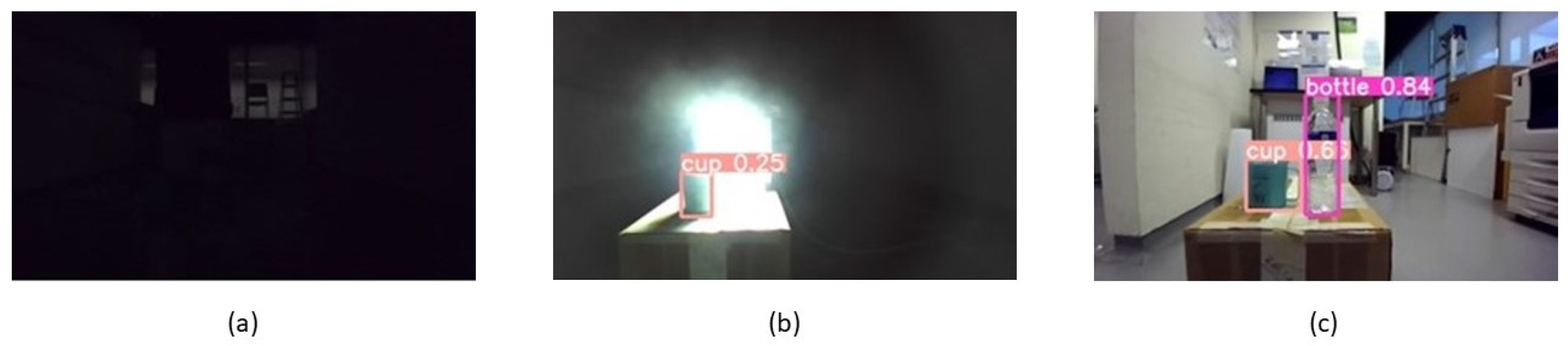
2.1. Effect of Lighting Condition on Object Detection

Robotic cameras require ideal lighting conditions for accurate functioning [31], much like human eyesight, which depends on a well-balanced lighting environment to operate well [32].
Under low light conditions, humans have trouble seeing details, identifying people, or navigating through environments, as human eyes are not designed to see well in the dark. Similarly, robot vision systems can have poor image quality due to inadequate lighting, which may hinder their ability to recognize shapes, identify objects, and navigate efficiently. Little or no illumination hinders the human or robot’s ability to perceive objects when solely relying on visual capabilities.
On the other hand, intense brightness or glare can be blinding and impede visual capabilities even for robotic cameras [33]. This behavior resembles how people squint or turn away from bright light or glare. Overexposure to light from glare or very bright light sources can cause washed-out photos or even momentary “blindness” in which the camera is unable to properly process any visual data due to a loss in visual definition caused by bright lights.
Therefore, the similarity between the lighting needs of humans and robot cameras encompasses both extremes of the lighting range. Robot cameras and human eyes have difficulties in environments that are either too bright or too dark, highlighting the necessity of well-balanced lighting settings for both natural and artificial vision systems to function optimally.
Given that mobile robots work in environments under a myriad of lighting conditions, they ought to be categorized to provide a basis for the RII scoring under the lux parameter (RII-Lux). The main categories for lighting conditions in various work environments defined for human comfort and requirements can be seen in Table 1. These lux values were referenced from international standards such as the ISO CIE 8995 [34] and its related documents relating to environmental lighting [35], along with BSI BS EN 17037:2018+A1:2021 [36].
Another factor to consider for hampering robotic vision performance would be glare. Glare is often caused by direct line-of-sight to bright lights or reflected off shiny surfaces, leading to whitened areas in the camera’s field of vision and causing diminished visual definition. Glare or intense brightness can negatively impact robotic visual capabilities by hindering the camera’s perception of object outlines, reducing visibility and tracking of certain landmarks or objects. Glare also results in the washing out of object details or outlines, causing robots to have navigational or localization issues due to loss of visual information or erroneous detection.
An overview of the proposed process for evaluating robot inclusivity based on lighting conditions is shown in Figure 1. Lux sensor data and camera input are used with the localization system to collect the illumination and glare data. The scoring and glare detection algorithm is then applied to analyze the collected data and generate three heatmaps, which would then show the lux distribution, glare, and RII-Lux, for a given site.

2.2. Measuring Light Intensity

To evaluate the lighting condition of an indoor site using a robot, we use the BH1750 light sensor (ywrobot, Tianjin, China) to determine illuminance levels in terms of lux. As part of our process, we identify a specific location and assess light intensity within the zone in a methodical manner to determine if they are suitable for robotic activities.
A BH1750 light sensor was affixed facing forward beside the robot’s camera to measure lux values. The forward-facing sensor would collect the indirect lux values as viewed by the robot’s camera. This setup is designed to provide a more accurate representation of the ambient light conditions during the robot’s motion.
The post-processed lux values would provide information to create a heatmap of the site’s light intensity. This data is required for the lux heatmap generation when evaluating the diversity of illumination conditions and their effects on robot inclusivity.

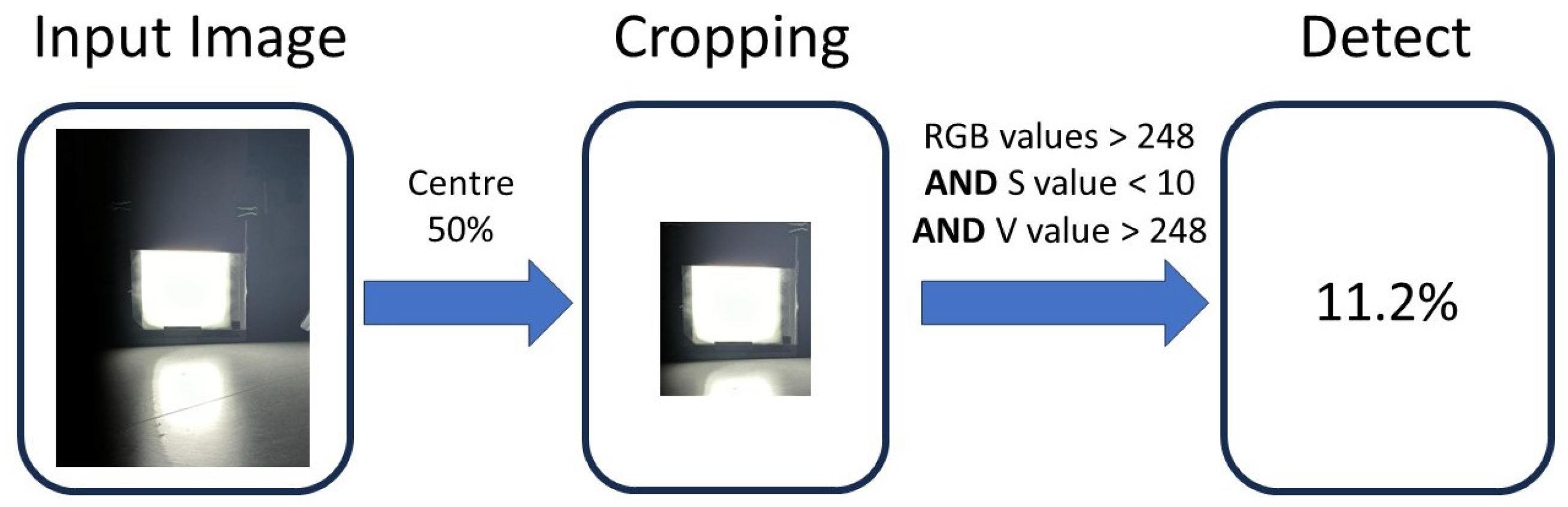
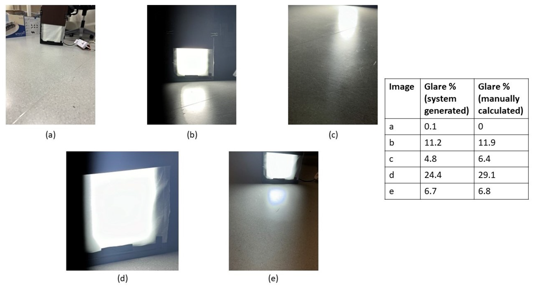
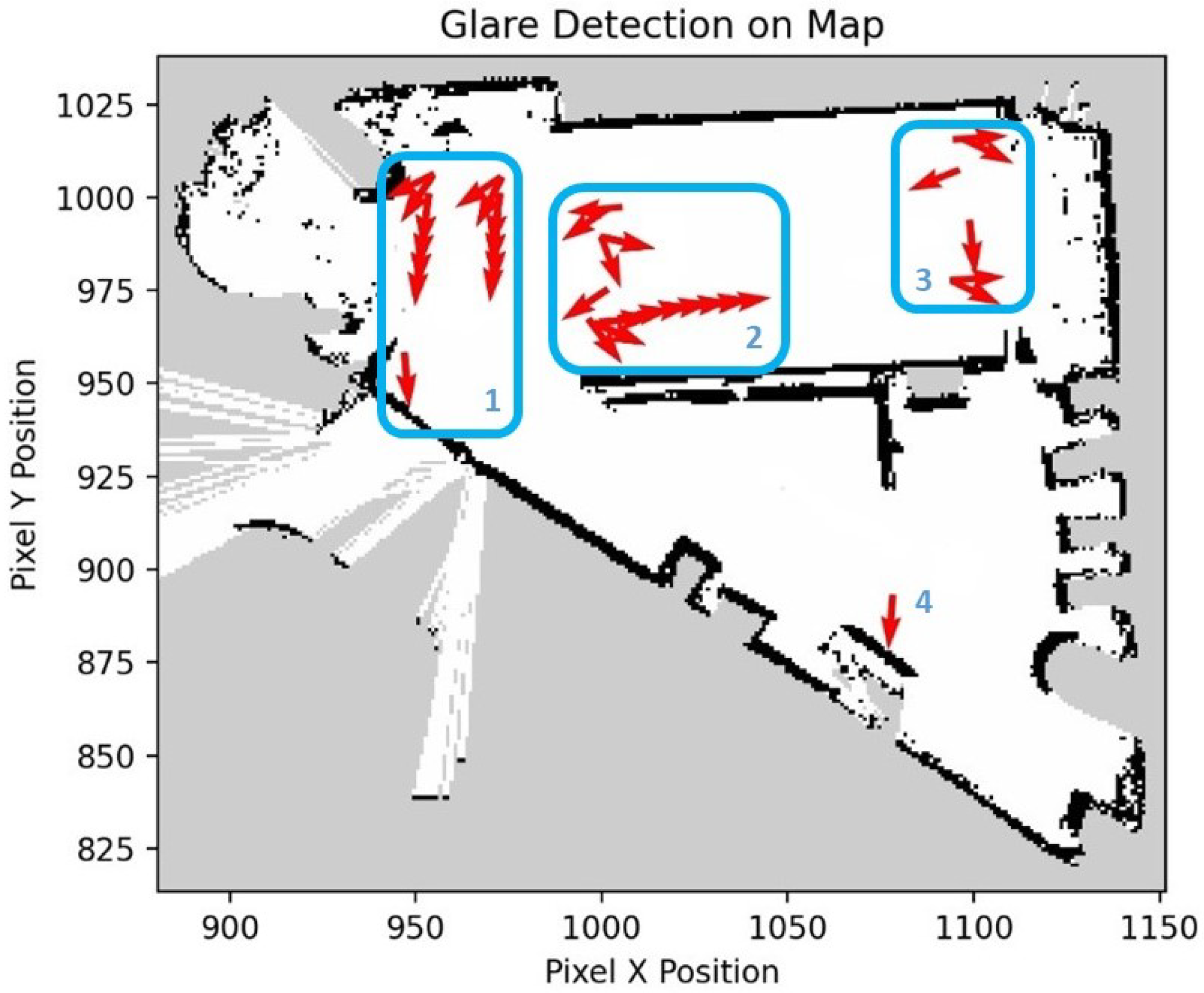
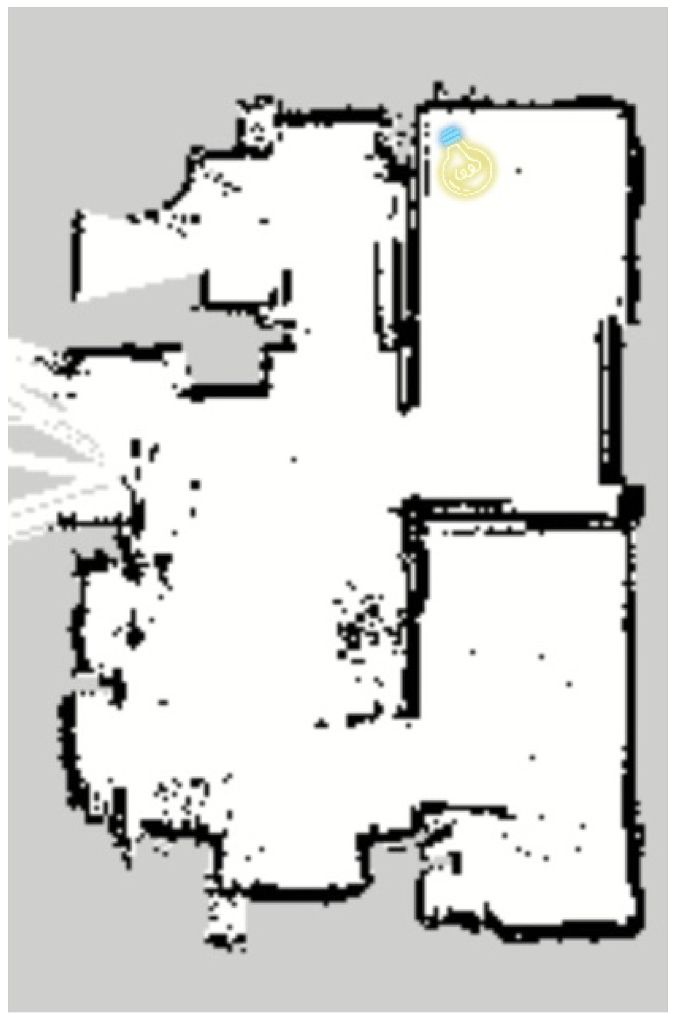
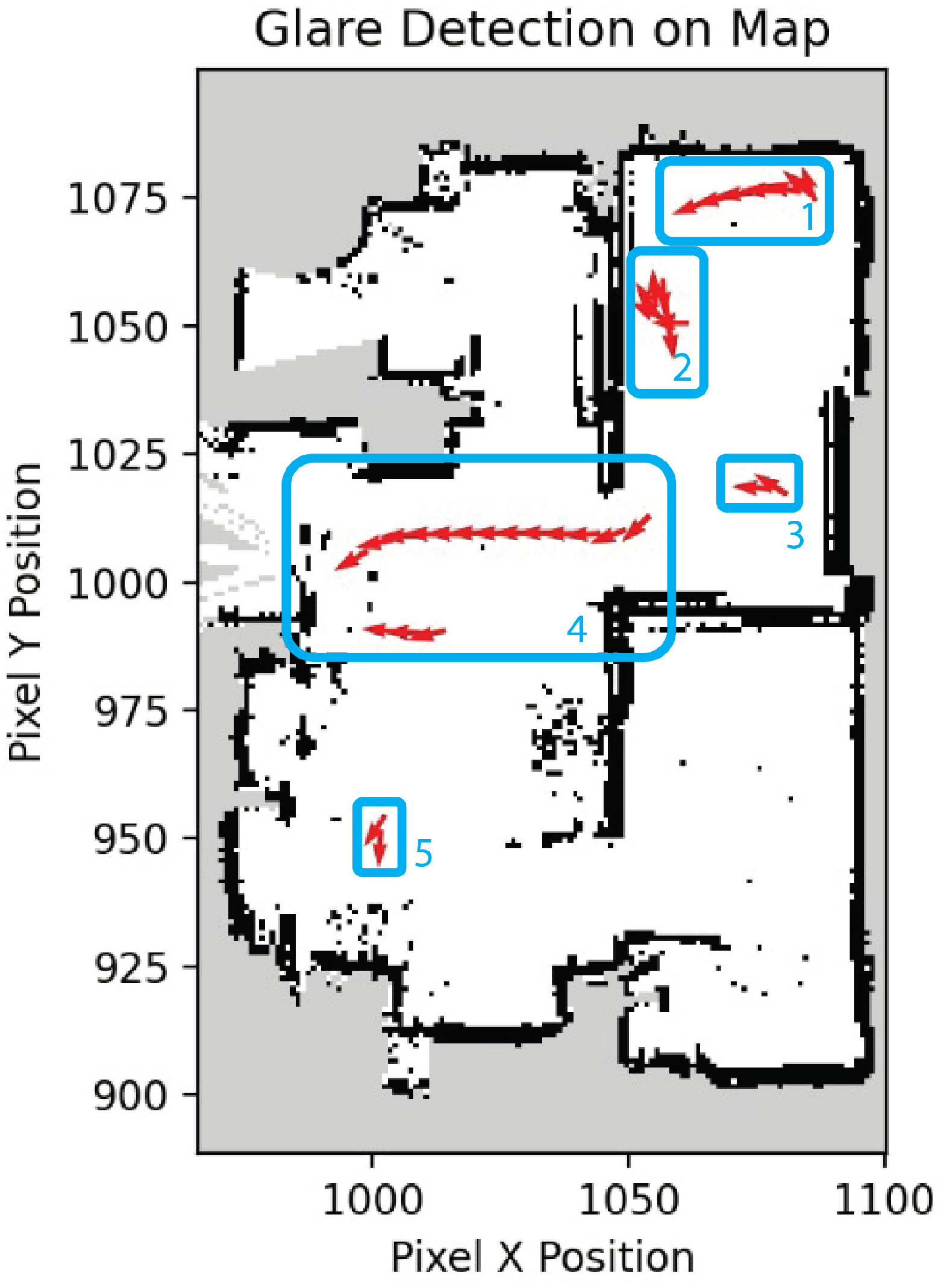
2.3. Identifying Glare

The camera of the robot is used to determine if glare is present during the robot’s operation. The livestream or recording of the camera view would be checked for instances of glare or lens flare. If there are instances of glare or any visual loss due to bright lighting, the location of the occurrences would be tagged on the site map. The algorithm for detecting the areas with glare through the audit robot’s point of view is described as pseudo-code in Algorithm 1.
Firstly, a video frame in full Red, Green, and Blue (RGB) color format is taken using a camera mounted on the robot. In scenarios where glare is concentrated on a specific segment of the image, cropping may be used to prevent a false detection because of the peripheral views from the camera. It would affect the object detection performance only when the glare is in the middle of the field of view. Thus, the algorithm would only focus on the central 50% of the camera view by applying the cropping method through the OpenCV library.
The RGB image is converted to Hue, Saturation, Value (HSV) color space. The image in HSV color space is also used to identify areas in the image with anomalous readings of brightness and color saturation. High values in the ‘Value’ channel denote brightness, while low values in the ‘Saturation’ channel indicate color washout.
Detecting glare within the image involves analyzing both the RGB and HSV components. Since glare typically manifests as bright, near-white pixels, a threshold R G B T of 248 (out of 256 maximum value indicating white color) for the RGB value was used. Pixels displaying values above this threshold in all three channels are identified as potential glare pixels. Similarly, in the HSV space, a threshold of 10 for the ‘Saturation’ component (defined as S T ) was used; pixels with values above 248 in the ‘Value’ channel (defined as V T ) and below S T in the ‘Saturation’ channel would thus indicate the presence of glare.
A binary glare mask is created based on these identified glare-affected pixels. This mask categorizes each pixel as either 0 (no glare) or 1 (glare). The percentage of the image affected by glare is calculated by determining the proportion of glare-marked pixels relative to the total pixel count of the image. This proportion is then multiplied by 100% to determine the final glare percentage. This process is visualized in Figure 2. Figure 3 shows example images and their corresponding glare value after the images were analyzed by the above algorithm before cropping. The glare percentages detected by the proposed method for glare detection and the manually calculated glare values are given in the figure for comparison. In general, the manually calculated glare percentage is slightly larger than the system-generated glare percentage because the calculation is performed based on the assumption that all the glare shapes are regular polygons. This comparison indicates that the glare detected by the method is accurate (average difference is about 1.5%). The glare detection algorithm runs at 30 frames per second. This run speed is sufficient for real-time operation.
Algorithm 1 Calculate Glare Percentage
  • Input: Image
  • Output: glarePercentage
  • if croppingNeeded then
  •      i m a g e CropCenter( i m a g e )
  • end if
  • h s v I m a g e ConvertToHSV( i m a g e )
  • g l a r e M a s k CreateEmptyMask(size of i m a g e )
  • for each p i x e l in i m a g e  do
  •     if IsBright( p i x e l ) and IsLowSaturation( p i x e l ) then
  •         MarkGlare( g l a r e M a s k , p i x e l )
  •     end if
  • end for
  • G l a r e P i x e l s     CountGlarePixels( g l a r e M a s k )
  • T o t a l P i x e l s     TotalPixels( i m a g e )
  • g l a r e P e r c e n t a g e     G l a r e P i x e l T o t a l P i x e l s   ×   100 %    
  • function IsBright( p i x e l )
  •     return  p i x e l . R G B   >   R G B _ T
  • end function   
  •  
  • function IsLowSaturation( p i x e l )
  •     return  p i x e l . S   <   S _ T and p i x e l . V   >   V _ T
  • end function

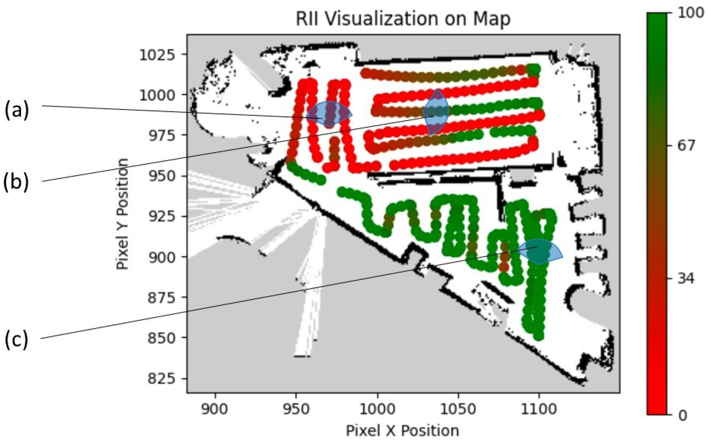
2.4. Quantifying the Robot-Inclusivity

To remove extreme lux sensor values, the raw lux readings would be normalized into a range of 0–100%, with the values exceeding 100 lux to be considered as 100%. This is to cap the lux values for areas that already have sufficient lux for typical indoor environments, as seen in Table 1.
As seen in Algorithm 2, the range of scoring is 0 to 100; we define the point system into three tiers. Areas of low light of 0–5 lux are categorized as ‘poor’, while environmental lux values of above 100 lux (as referenced by the minimum lux required for indoor office spaces in Table 1) would be categorized as ‘ideal’. Lux sensor inputs between these two threshold values would be considered as ‘acceptable’.
If glare is detected, the score for that grid cell’s RII-Lux score is given a penalty factor of 34 (100 divided by 3 and rounded up) to quantify the reduction in robotic performance caused by visual loss from glare and drop-down a RII-lux tier. Negative values after the glare score penalty would be changed to have a score of 0 instead. This process is detailed in Algorithm 2. The remapped values are then used to color code the grid. The areas with RII-Lux close to 100 are colored green, while values close to 0 (i.e., extremely dark/bright zones or areas with glare) are colored red. This color coding would help in visually representing the auditing results for the sake of understanding and possible use for robot path planning.
Algorithm 2 Calculate RII-Lux
  • Input:  l u x v a l u e , glare, position
  • output: RII-Lux, position tagging for robot inclusivity    
  •  
  • if  l u x v a l u e 5   then
  •     Map( l u x v a l u e , 0 5 , 0 33 , g l a r e , p o s i t i o n )
  • else if  6 l u x v a l u e 99   then
  •     Map( l u x v a l u e , 6 99 , 34 66 , g l a r e , p o s i t i o n )
  • else
  •     Map( l u x v a l u e , 100 l u x . M a x , 67 100 , g l a r e , p o s i t i o n )
  • end if   
  •  
  • function Map( l u x v a l u e , R O , R N , g l a r e )
  •     RII-Lux = ( l u x v a l u e R O . M i n ) ( R O . M a x R O . M i n ) ( R N . M a x R N . M i n ) + R N . M i n
  •     if  g l a r e = Yes then
  •         RII-Lux = R I I 34
  •     end if
  •     Tagged RII-Lux on p o s i t i o n
  • end function

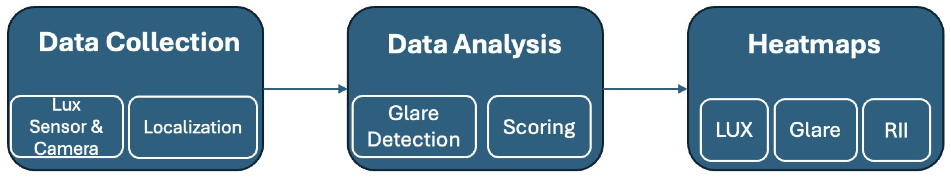
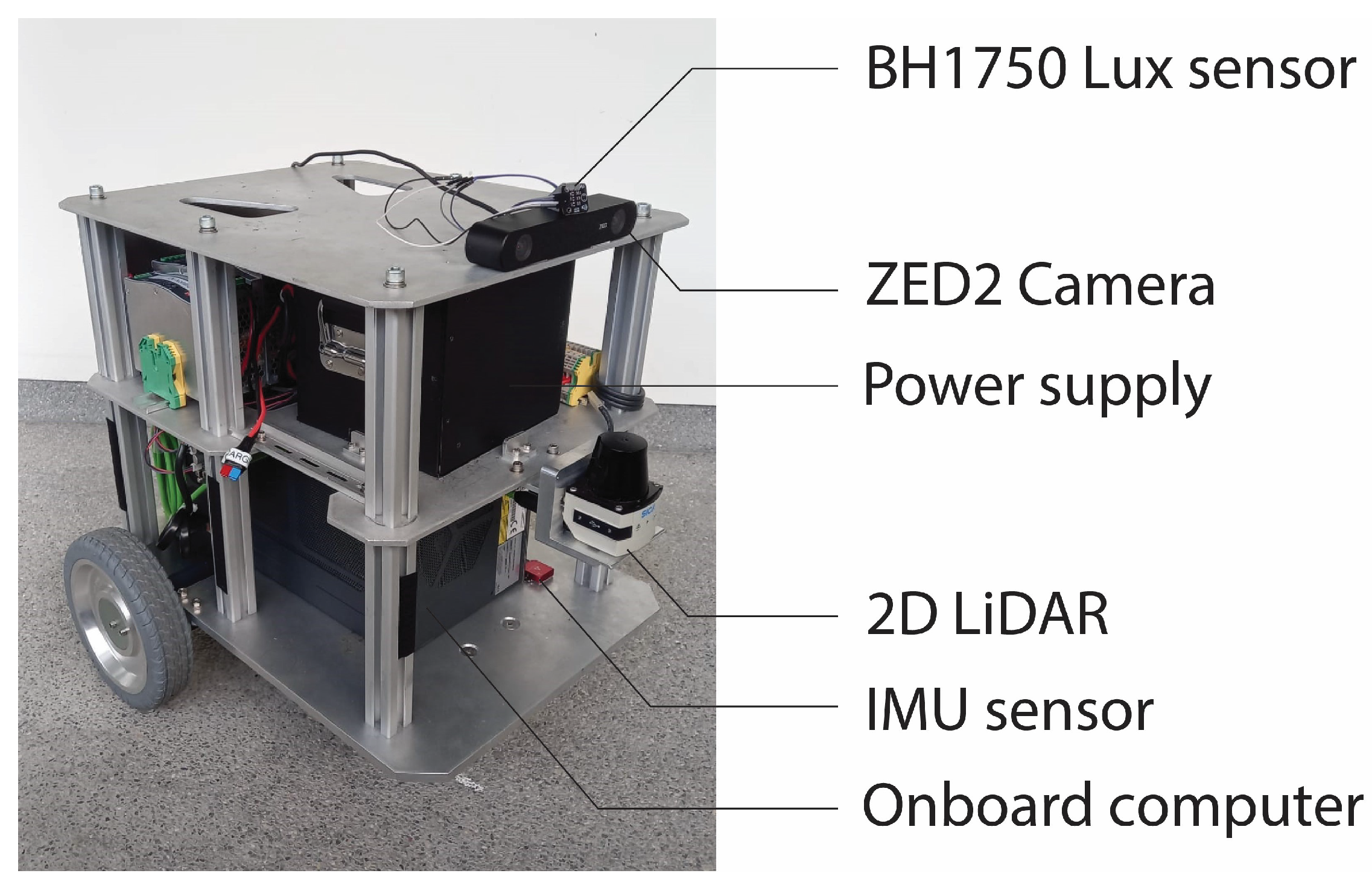
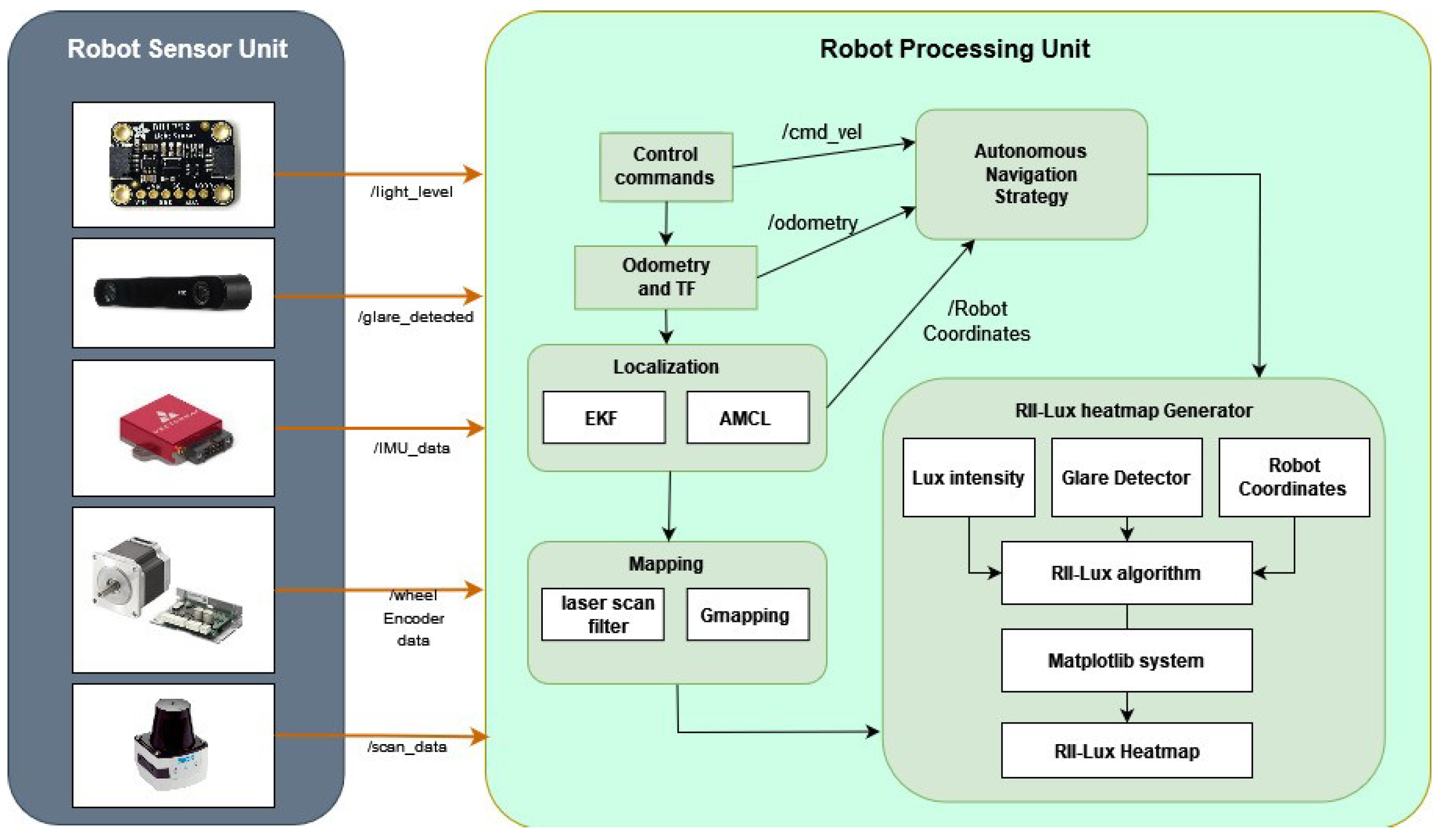
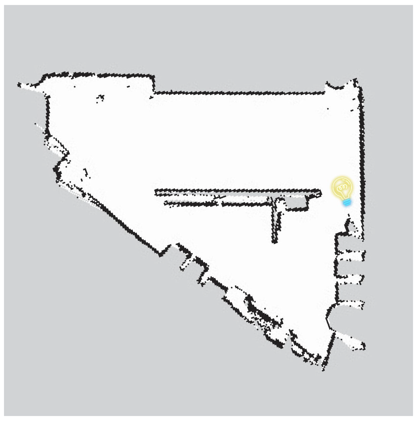
3. Automated RII Map Generation

The Meerkat robot is used to implement the autonomous auditing process for RII-Lux in a given environment. The robot was made to pass through the area in a zigzag area coverage method to cover the site to obtain the lux values as thoroughly as possible, while enabling the robot to detect and tagging the existing glare. This movement pattern is chosen to maximize area coverage while maintaining an efficient path for the robot. The Meerkat possesses basic navigation and obstacle avoidance capabilities and has differential-drive locomotion as the means of travel. The components of the Meerkat robot are shown in Figure 4.
The BH1750 lux sensor is mounted on the Meerkat robot facing forward near its optical camera to better emulate the lux values obtained by the camera during operation. The averaged lux sensor readings are tagged onto the map generated by the 2D LIDAR (SICK, Singapore) when the robot passes over the locations determined by the grid cell centers. The minimum and maximum lux values of an audited site are used to generate a lux value range. The lux value range is then normalized into a linear scale for color coding of the heatmap.
A ZED2 camera is mounted at the front of the robot for object detection and glare identification. A real-time glare detection program is executed on the robot as outlined in Algorithm 1. When glare exceeds a threshold of 10% (as determined by the cutoff value in Section 2.3), the robot’s current orientation and position values are used to tag an arrow on the map to indicate where the source of glare is detected.
To ensure accuracy in glare detection, especially in scenarios where the robot’s wide camera view might differ from the actual glare source, only the central 50% of the camera’s view is utilized for this purpose by using the cropping process described in Section 2.3. This selective focus enhances the precision of the detection mechanism.
With the lux sensor, ZED stereo-vision camera (Stereolabs, San Francisco, CA, USA), Inertial Measurement Unit (IMU), motor encoders, and 2D LIDAR, the robot is able to measure the lux value of the environment and detect the existing glare with high accuracy of localization. Robot Operating System (ROS) is used for data communication, mapping, and localization (see the software architecture of the robot depicted in Figure 5). The localization data and input from the sensors are collected to quantify and create the heatmap via the Matplot-lib library.

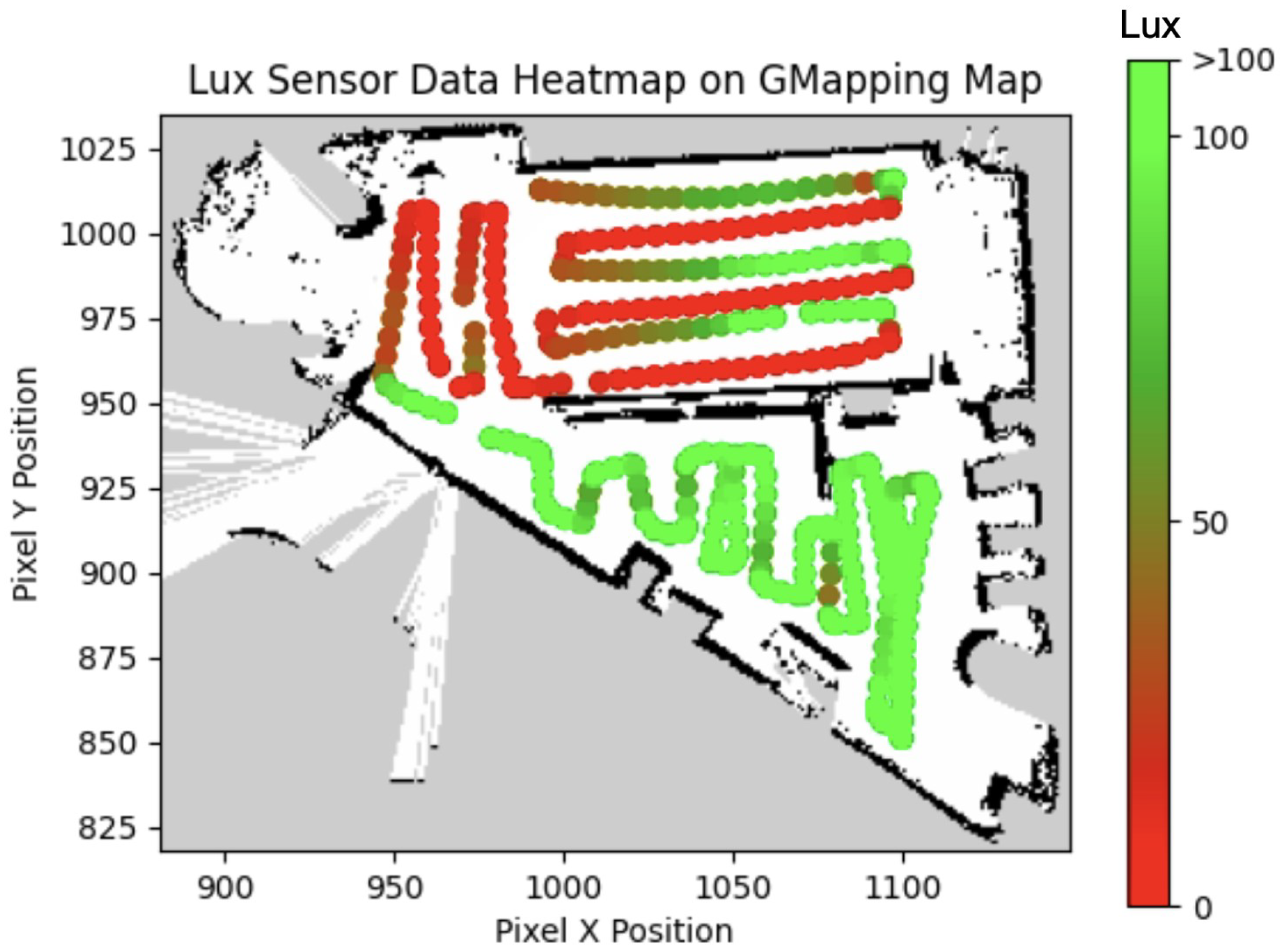
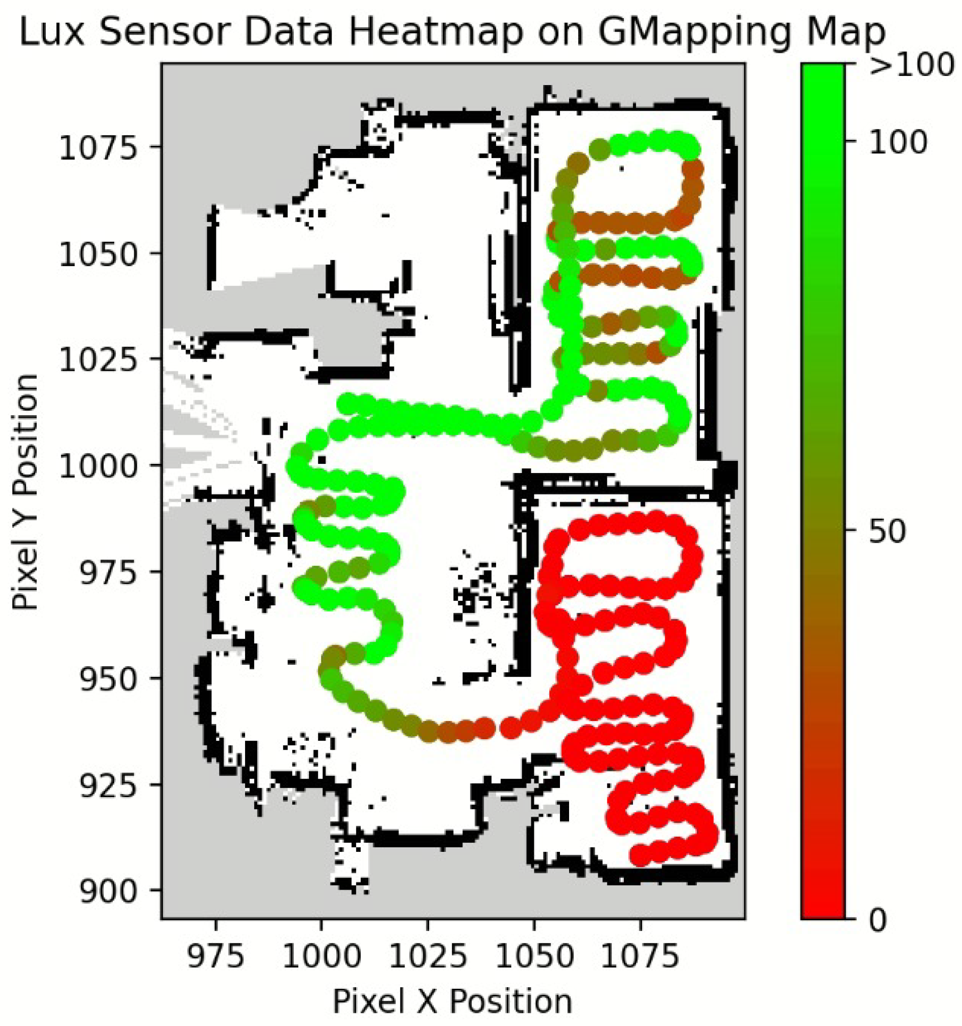
4. Experimental Validation

Two sites with distinct characteristics were chosen to evaluate the proposed auditing framework.

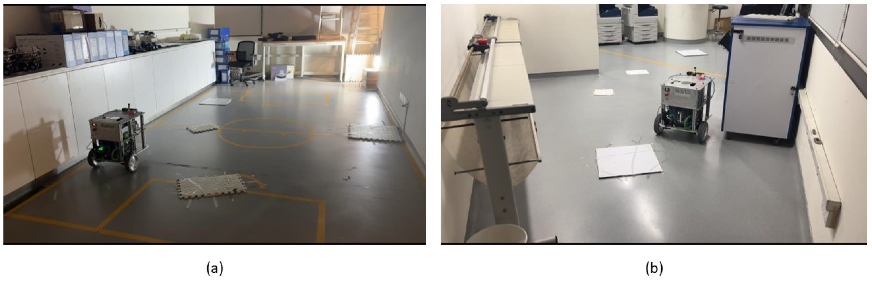
4.1. Site 1: Printing Room

A fabrication/printing room within the Singapore University of Technology and Design (SUTD) campus was chosen as the first site. The obtained LIDAR map (from the robot’s 2D LIDAR) is shown in Figure 6. Figure 7 shows images taken from the site layout for our experiment. The site had two different lighting conditions; the top half of the site plan image with reference to Figure 6 was made dark, while the area for the bottom half had lights turned on. The two zones were separated by a center divider wall in the room. A spotlight of LED array 100 W was placed at the intersection between the darkened and lit areas of the room represented by the lightbulb in Figure 6. Obstacles were placed on the floor to introduce ground obstacles. The audit robot was operated on this site to collect the data and generate the RII-Lux heatmap.
The colored grid for the lux values recorded by the robot is shown in Figure 8, while the glare map is given in Figure 9. The information of the two maps is then fused to generate the RII-Lux heatmap shown in Figure 10. This map is generated based on the lux sensor values as a visual representation for RII-lux.
According to the lux value heatmap in Figure 8, most of the upper half of the site recorded values below 100 lux, while some parts near the spotlight recorded values above 100 lux. The upper half of the site map has its ceiling lights turned off and is only partially lit by the spotlight and its reflection. Therefore, lower lux values are expected. As the reflection of the spotlight is unable to reach the center of the room, locations with very low lux would be tagged on the map. These spots are also visible in the lux value heatmap as a few red data points in the middle. The bottom half of the site was illuminated by fluorescent ceiling lights. Thus, most areas are under good lighting conditions yielding to above 100 lux, and only a few places are slightly below 100 due to the shadows.
Figure 9 shows the generated heatmap based on the camera glare detection. Cluster 1 of the red arrows resulted from the glare caused by external light entering from the corridor through the room’s glass doors. Clusters 2 and 3 were caused by the spotlight. Arrow 4 was due to stray light coming in from the window. Therefore, the glare detection map is agreeable with the environment setting. The marked locations, where glare is detected, lead to RII-Lux score deduction from the mapped RII score from lux values.
The generated RII-Lux heatmap shown in Figure 10 matches the lighting conditions of the printing room site per the manual observations. An object detection test setup was also used to access the correlation between the RII-Lux heatmap generated by the proposed framework and the accuracy of computer vision-based object detection. This process provided an objective assessment for the validation. In this regard, three distinct locations from the RII-Lux map were selected as samples (marked as ‘a’, ‘b’, and ‘c’ in Figure 10). A cup and bottle were used as objects to be detected, and the same objects were placed on these locations. Then, the detection rates of those objects were analyzed. YOLOv8 pretrained with COCO image dataset [37] was used in this regard. ZED2 camera was used to capture the images. The captured images at these locations are shown in Figure 11 with corresponding detection results.
The view from the camera, along with the detection results at the location ‘a’, is shown in Figure 11a. The detection system could not detect the objects in this instance, suggesting the unsuitability of the lighting conditions. According to the heat map, the RII-Lux corresponding to this location is 0, which agrees with the detection results. Figure 11b shows the detection results at location ‘b’. Here, the system correctly detected only one object out of two, suggesting the partial suitability of lighting. The corresponding RII-Lux value is 53, which matches the detection accuracy. The location ‘c’ has an RII-Lux of 98, suggesting that the lighting at the location is perfect for detection. Similar results were obtained from the detection test as shown in Figure 11c, where both objects were correctly detected with reasonable confidence. These results show that the RII-Lux heatmap generated by the proposed auditing framework positively correlates with object detection accuracy.

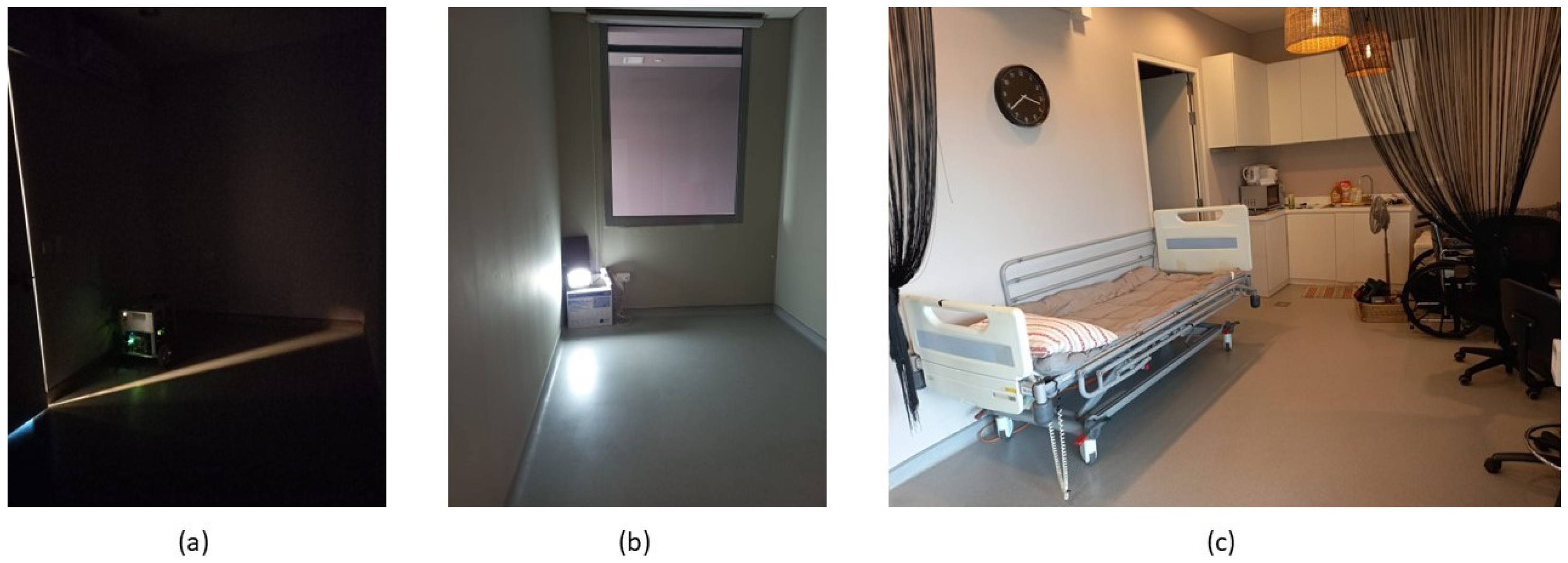
4.2. Site 2: Mock Living Space

The second site used for testing the proposed auditing framework was a mock-up living space. The zone consists of a living room that connects to three other smaller rooms, as seen in Figure 12. With reference to Figure 13, one room was made to be as dark as possible to provide different lighting conditions (Figure 13a), while another was made to include the spotlight for glare (Figure 13b). The living room was used to provide a control lighting condition for a normally lit indoor environment (Figure 13c). The location of the spotlight is represented by the lightbulb icon in the LIDAR map.
The variation in the lux data perceived by the robot is visualized in Figure 14. Figure 15 shows the results of the detected glare within the mock living space site. Arrow clusters 1 and 2 correspond to the glare detected from the spotlight and doorway. Arrow clusters 3 and 4 show the glare detected from the main doorway, while arrow cluster 5 depicts glare reflected from furniture parts in the living room. The RII-Lux heatmap generated by the proposed framework by combining the results from both the lux data and glare detection is shown in Figure 16. This heatmap agrees with the variation in lux values and the glare locations per the observations.
Similar to test site 1 above, the same object detection test setup was used to assess the validity of the generated RII-Lux heatmap of site 2. Three locations were selected (labeled as ‘a’, ‘b’, and ‘c’ in Figure 16) for this assessment.
The object detection results are given in Figure 17. In location ‘a’, the RII-Lux value is 0, indicating unsuitability for the robot vision system (see Figure 16). The detection test failed to accurately recognize any object in this location (see Figure 17a), demonstrating the unsuitability of the location for the robot operation. Figure 17b shows the detection results at the zone with spotlight glare (i.e., ‘b’), and the system correctly detected only one object out of two, suggesting the partial suitability of the lighting conditions where the RII-Lux is 45. According to Figure 17c, both objects were correctly detected with reasonable confidence in location ‘c’, indicating the suitability of the lighting condition. Here, the RII-Lux is 97, which indicates the suitability of the lighting condition for the operation of a robot with a vision system. These results show that the RII-Lux heatmap generated by the proposed auditing framework positively correlates with object detection accuracy in site 2 as well.

5. Conclusions

This paper proposed a novel framework for auditing the Robot Inclusivity Index (RII) of indoor environments based on lighting conditions. This framework measures the light intensity using a sensor and the presence of glare using a camera. The DfR principles were used to establish a quantifiable relationship between RII and environment lighting conditions (defined as RII-Lux). This relationship is applied to convert the perceived light conditions to RII-Lux values. The proposed framework has been implemented on the Meerkat robot for autonomous auditing and generating RII-Lux heatmaps for indoor environments.
The experimental results validated that the proposed framework can autonomously audit a given environment and generate the corresponding RII-Lux heatmap. Furthermore, the RII-Lux values determined by the system positively correlate with the object detection accuracy. This lux heatmap would inform building owners of the zones not optimal for a robot’s operation due to the poor lighting conditions for avoidance or rectification to enable robots to work safely in them.
To improve lighting conditions for humans and robots alike, one has to consider the feasibility of an even distribution of lighting in the environment for robot deployments to reduce incidents of glare or strong beams of light. Some methods can include implementing shades to moderate the amount of direct sunlight entering the building or using optic diffusers to redistribute light around the zone for better visibility by robot visual cameras and visual comfort to the human eye. However, attention to human comfort and requirements should be properly traded off with a robot’s requirements.
The current work only takes illumination into consideration apart from glare, while object detection is also affected by other lighting factors, such as color temperature and background colors. Therefore, the extension of the proposed framework to include other influential parameters is proposed for future work for RII-Lux calculation. Furthermore, the scope of this work considers only static environmental conditions. The consideration of dynamic changes in lighting factors for auditing the robot inclusivity is also proposed for future work.

Author Contributions

Conceptualization: M.R.E., Z.Z. and M.A.V.J.M.; Data curation: Z.Z., C.S.C.S.B. and M.S.K.Y.; Formal analysis: Z.Z., M.A.V.J.M., M.B. and Y.W.; Funding acquisition: M.R.E.; Investigation: Z.Z., C.S.C.S.B. and M.S.K.Y.; Methodology: M.S.K.Y., Z.Z. and M.A.V.J.M.; Project administration: M.R.E.; Resources: M.R.E.; Software: Z.Z. and C.S.C.S.B.; Supervision: M.R.E. and M.A.V.J.M.; Validation: Z.Z. and C.S.C.S.B.; Visualization: M.S.K.Y. and Z.Z.; Writing—original draft: Z.Z. and M.S.K.Y.; Writing—review and editing: M.A.V.J.M., M.B. and Y.W. All authors have read and agreed to the published version of the manuscript.

Funding

This research is supported by the National Robotics Programme under its National Robotics Programme (NRP) BAU, Ermine III: Deployable Reconfigurable Robots, Award No. M22NBK0054 and also supported by A*STAR under its “RIE2025 IAF-PP Advanced ROS2-native Platform Technologies for Cross-sectorial Robotics Adoption (M21K1a0104)” programme.

Data Availability Statement

The original contributions presented in the study are included in the article, further inquiries can be directed to the corresponding authors.

Conflicts of Interest

The authors declare no conflicts of interest.

Abbreviations

The following abbreviations are used in this manuscript:
DfRDesign for Robot
RII-LuxRobot-Inclusivity Index based on Lighting
RGBRed-Green-Blue
HSVHue, Saturation, Value
ROSRobot Operating System

References

  1. Chibani, A.; Amirat, Y.; Mohammed, S.; Matson, E.; Hagita, N.; Barreto, M. Ubiquitous robotics: Recent challenges and future trends. Robot. Auton. Syst. 2013, 61, 1162–1172. [Google Scholar] [CrossRef]
  2. Wijegunawardana, I.D.; Muthugala, M.A.V.J.; Samarakoon, S.M.B.P.; Hua, O.J.; Padmanabha, S.G.A.; Elara, M.R. Insights from autonomy trials of a self-reconfigurable floor-cleaning robot in a public food court. J. Field Robot. 2024, 41, 811–822. [Google Scholar] [CrossRef]
  3. Santhanaraj, K.K.; MM, R. A survey of assistive robots and systems for elderly care. J. Enabling Technol. 2021, 15, 66–72. [Google Scholar] [CrossRef]
  4. Bernardo, R.; Sousa, J.M.; Gonçalves, P.J. Survey on robotic systems for internal logistics. J. Manuf. Syst. 2022, 65, 339–350. [Google Scholar] [CrossRef]
  5. Vásquez, B.P.E.A.; Matía, F. A tour-guide robot: Moving towards interaction with humans. Eng. Appl. Artif. Intell. 2020, 88, 103356. [Google Scholar] [CrossRef]
  6. Thotakuri, A.; Kalyani, T.; Vucha, M.; Chinnaaiah, M.; Nagarjuna, T. Survey on robot vision: Techniques, tools and methodologies. Int. J. Appl. Eng. Res. 2017, 12, 6887–6896. [Google Scholar]
  7. Premebida, C.; Ambrus, R.; Marton, Z.C. Intelligent robotic perception systems. In Applications of Mobile Robots; IntechOpen: London, UK, 2018; pp. 111–127. [Google Scholar]
  8. Asadi, K.; Ramshankar, H.; Pullagurla, H.; Bhandare, A.; Shanbhag, S.; Mehta, P.; Kundu, S.; Han, K.; Lobaton, E.; Wu, T. Vision-based integrated mobile robotic system for real-time applications in construction. Autom. Constr. 2018, 96, 470–482. [Google Scholar] [CrossRef]
  9. Bodenhagen, L.; Fugl, A.R.; Jordt, A.; Willatzen, M.; Andersen, K.A.; Olsen, M.M.; Koch, R.; Petersen, H.G.; Krüger, N. An adaptable robot vision system performing manipulation actions with flexible objects. IEEE Trans. Autom. Sci. Eng. 2014, 11, 749–765. [Google Scholar] [CrossRef]
  10. Davison, A.J. Mobile Robot Navigation Using Active Vision. 1999. Available online: https://www.robots.ox.ac.uk/ActiveVision/Papers/davison_dphil1998/davison_dphil1998.pdf (accessed on 10 January 2024).
  11. Steffens, C.R.; Messias, L.R.V.; Drews, P.J.L., Jr.; da Costa Botelho, S.S. On Robustness of Robotic and Autonomous Systems Perception. J. Intell. Robot. Syst. 2021, 101, 61. [Google Scholar] [CrossRef]
  12. Amanatiadis, A.; Gasteratos, A.; Papadakis, S.; Kaburlasos, V. Image stabilization in active robot vision. In Robot Vision; Intech Open: London, UK, 2010; pp. 261–274. [Google Scholar]
  13. Tung, C.; Kelleher, M.R.; Schlueter, R.J.; Xu, B.; Lu, Y.H.; Thiruvathukal, G.K.; Chen, Y.K.; Lu, Y. Large-scale object detection of images from network cameras in variable ambient lighting conditions. In Proceedings of the 2019 IEEE Conference on Multimedia Information Processing and Retrieval (MIPR), San Jose, CA, USA, 28–30 March 2019; pp. 393–398. [Google Scholar]
  14. Ali, I.; Suominen, O.; Gotchev, A.; Morales, E.R. Methods for simultaneous robot-world-hand–eye calibration: A comparative study. Sensors 2019, 19, 2837. [Google Scholar] [CrossRef]
  15. Se, S.; Lowe, D.; Little, J. Local and global localization for mobile robots using visual landmarks. In Proceedings of the 2001 IEEE/RSJ International Conference on Intelligent Robots and Systems, Expanding the Societal Role of Robotics in the the Next Millennium (Cat. No. 01CH37180), Maui, HI, USA, 29 October–3 November 2001; Volume 1, pp. 414–420. [Google Scholar]
  16. Zhang, T.; Cong, Y.; Dong, J.; Hou, D. Partial visual-tactile fused learning for robotic object recognition. IEEE Trans. Syst. Man Cybern. Syst. 2021, 52, 4349–4361. [Google Scholar] [CrossRef]
  17. Tarokh, M.; Merloti, P. Vision-based robotic person following under light variations and difficult walking maneuvers. J. Field Robot. 2010, 27, 387–398. [Google Scholar] [CrossRef]
  18. Grift, T.; Zhang, Q.; Kondo, N.; Ting, K. A review of automation and robotics for the bio-industry. J. Biomechatron. Eng. 2008, 1, 37–54. [Google Scholar]
  19. Ge, W.; Chen, S.; Hu, H.; Zheng, T.; Fang, Z.; Zhang, C.; Yang, G. Detection and localization strategy based on YOLO for robot sorting under complex lighting conditions. Int. J. Intell. Robot. Appl. 2023, 7, 589–601. [Google Scholar] [CrossRef]
  20. Skinner, J.; Garg, S.; Sünderhauf, N.; Corke, P.; Upcroft, B.; Milford, M. High-fidelity simulation for evaluating robotic vision performance. In Proceedings of the 2016 IEEE/RSJ International Conference on Intelligent Robots and Systems (IROS), Daejeon, Republic of Korea, 9–14 October 2016; pp. 2737–2744. [Google Scholar]
  21. Yeo, M.S.K.; Samarakoon, S.M.B.P.; Ng, Q.B.; Ng, Y.J.; Muthugala, M.A.V.J.; Elara, M.R.; Yeong, R.W.W. Robot-Inclusive False Ceiling Design Guidelines. Buildings 2021, 11, 600. [Google Scholar] [CrossRef]
  22. Mohan, R.E.; Tan, N.; Tjoelsen, K.; Sosa, R. Designing the robot inclusive space challenge. Digit. Commun. Netw. 2015, 1, 267–274. [Google Scholar] [CrossRef]
  23. Kiat Yeo, M.S.; Boon Ng, A.Q.; Jin Ng, T.Y.; Mudiyanselage, S.; Samarakoon, B.P.; Muthugala, M.A.V.J.; Mohan, R.E.; Ng, D.T. Robot-Inclusive Guidelines for Drain Inspection. In Proceedings of the 2021 8th International Conference on Information Technology, Computer and Electrical Engineering (ICITACEE), Semarang, Indonesia, 23–24 September 2021; pp. 7–12. [Google Scholar] [CrossRef]
  24. Yeo, M.S.K.; Samarakoon, S.M.B.P.; Ng, Q.B.; Muthugala, M.A.V.J.; Elara, M.R. Design of Robot-Inclusive Vertical Green Landscape. Buildings 2021, 11, 203. [Google Scholar] [CrossRef]
  25. Verne, G.B. Adapting to a robot: Adapting gardening and the garden to fit a robot lawn mower. In Proceedings of the Companion of the 2020 ACM/IEEE International Conference on Human-Robot Interaction, Cambridge, UK, 23–26 March 2020; pp. 34–42. [Google Scholar]
  26. Tan, N.; Mohan, R.E.; Watanabe, A. Toward a framework for robot-inclusive environments. Autom. Constr. 2016, 69, 68–78. [Google Scholar] [CrossRef]
  27. Jocelyn, S.; Burlet-Vienney, D.; Giraud, L.; Sghaier, A. Collaborative Robotics: Assessment of Safety Functions and Feedback from Workers, Users and Integrators in Quebec. 2019. Available online: https://www.irsst.qc.ca/media/documents/PubIRSST/R-1030.pdf?v=2021-10-02 (accessed on 10 January 2024).
  28. Hippertt, M.P.; Junior, M.L.; Szejka, A.L.; Junior, O.C.; Loures, E.R.; Santos, E.A.P. Towards safety level definition based on the HRN approach for industrial robots in collaborative activities. Procedia Manuf. 2019, 38, 1481–1490. [Google Scholar] [CrossRef]
  29. Saenz, J.; Behrens, R.; Schulenburg, E.; Petersen, H.; Gibaru, O.; Neto, P.; Elkmann, N. Methods for considering safety in design of robotics applications featuring human-robot collaboration. Int. J. Adv. Manuf. Technol. 2020, 107, 2313–2331. [Google Scholar] [CrossRef]
  30. Sandoval, E.B.; Sosa, R.; Montiel, M. Robot-Ergonomics: A proposal for a framework in HRI. In Proceedings of the Companion of the 2018 ACM/IEEE International Conference on Human-Robot Interaction, Chicago, IL, USA, 5–8 March 2018; pp. 233–234. [Google Scholar]
  31. Chen, S.; Zhang, J.; Zhang, H.; Kwok, N.; Li, Y.F. Intelligent lighting control for vision-based robotic manipulation. IEEE Trans. Ind. Electron. 2011, 59, 3254–3263. [Google Scholar] [CrossRef]
  32. Konstantzos, I.; Sadeghi, S.A.; Kim, M.; Xiong, J.; Tzempelikos, A. The effect of lighting environment on task performance in buildings—A review. Energy Build. 2020, 226, 110394. [Google Scholar] [CrossRef]
  33. Chen, S.; Zhang, J.; Zhang, H.; Wang, W.; Li, Y. Active illumination for robot vision. In Proceedings of the 2007 IEEE International Conference on Robotics and Automation, Rome, Italy, 10–14 April 2007; pp. 411–416. [Google Scholar]
  34. ISO/CIE 8995-3:2018; Lighting of Work Places. ISO: Geneva, Switzerland, 2018. Available online: https://www.iso.org/standard/70593.html (accessed on 10 January 2024).
  35. ISO/TC 274; Light and Lighting. DIN: Berlin, Germany, 2023.
  36. BS EN 17037:2018+A1:2021; Daylight in Buildings. BSI: London, UK, 2021.
  37. Sohan, M.; Sai Ram, T.; Reddy, R.; Venkata, C. A Review on YOLOv8 and Its Advancements. In Proceedings of the International Conference on Data Intelligence and Cognitive Informatics; Springer: Berlin/Heidelberg, Germany, 2024; pp. 529–545. [Google Scholar]
Figure 1. Overview of RII-Lux process.
Buildings 14 01110 g001
Figure 2. The process of glare detection.
Buildings 14 01110 g002
Figure 3. (ae) are sample images used and their corresponding glare values before cropping. The manual calculations for each image’s glare percentages are also given here for comparison.
Buildings 14 01110 g003
Figure 4. Meerkat audit robot and its specifications.
Buildings 14 01110 g004
Figure 5. Meerkat software architecture.
Buildings 14 01110 g005
Figure 6. 2D Lidar map of the site 1: printing room site. The location and orientation of the LED spotlight is depicted by the lightbulb symbol at right of diagram.
Buildings 14 01110 g006
Figure 7. View of the site 1: printing room. (a) dark area (b) illuminated area.
Buildings 14 01110 g007
Figure 8. Lux heatmap for site 1.
Buildings 14 01110 g008
Figure 9. Glare map for site 1. Arrows indicate the glare detected instances and the direction.
Buildings 14 01110 g009
Figure 10. Generated RII-Lux heatmap. (ac) annotate the location chosen for object-detection test setup.
Buildings 14 01110 g010
Figure 11. Detection results during the validation of site 1; (ac) are the locations ‘a’, ‘b’, and ‘c’ in Figure 10.
Buildings 14 01110 g011
Figure 12. 2D Lidar map of site 2: Mock Living Space, location and orientation of the spotlight depicted by the lightbulb symbol.
Buildings 14 01110 g012
Figure 13. Views of the site 2: mock living space site. (a) darkened room; (b) room with spotlight; (c) living room with typical lighting conditions.
Buildings 14 01110 g013
Figure 14. Lux heatmap for site 2.
Buildings 14 01110 g014
Figure 15. Glare map for site 2. Arrowheads indicate the glare-detected instances and the direction. Arrowheads are grouped together into the numbered arrow clusters for reference in text.
Buildings 14 01110 g015
Figure 16. Generated RII-lux heatmap for site 2. (ac) annotate the location chosen for object-detection test setup.
Buildings 14 01110 g016
Figure 17. Detection results during the validation in site 2; (a) darkened room, (b) objects backlit by LED spotlight, (c) typical indoor lighting conditions.
Buildings 14 01110 g017
Table 1. Typical lux levels for common robotic workspaces.
Lighting EnvironmentLux Level Range (Lux)Conditions
OutdoorsMorning/Evening: 10–1000 Noon: 10000 Overcast/cloudy: 1000Outdoors, varying levels/colours due to position of sun in the sky
Office100–300Indoors, batch/area control
Retail200–500Indoors, area control, may have uneven lighting
Residential200–300Indoors, individual control, point/linear/cove lighting
Industrial300–700Indoors, batch control, spotlight lighting, evenly-distributed lighting
Disclaimer/Publisher’s Note: The statements, opinions and data contained in all publications are solely those of the individual author(s) and contributor(s) and not of MDPI and/or the editor(s). MDPI and/or the editor(s) disclaim responsibility for any injury to people or property resulting from any ideas, methods, instructions or products referred to in the content.

