
Design and Simulation for Technological Integration of Bio-Based Components in Façade System Modules

 ,
,  ,
,  , ,
, ,  , ,
, ,
Abstract
:1. Introduction
- Design bio-composed pultruded bar for profiles for the frame of façade system modules.
- Validate the bio-composed pultruded profile for the frame of façade system modules with mechanical simulations.
- Define alternative materials and components to support the introduction of eco-friendly solutions replacing conventional ones in prefabricated façade systems for insulation and tightness systems.
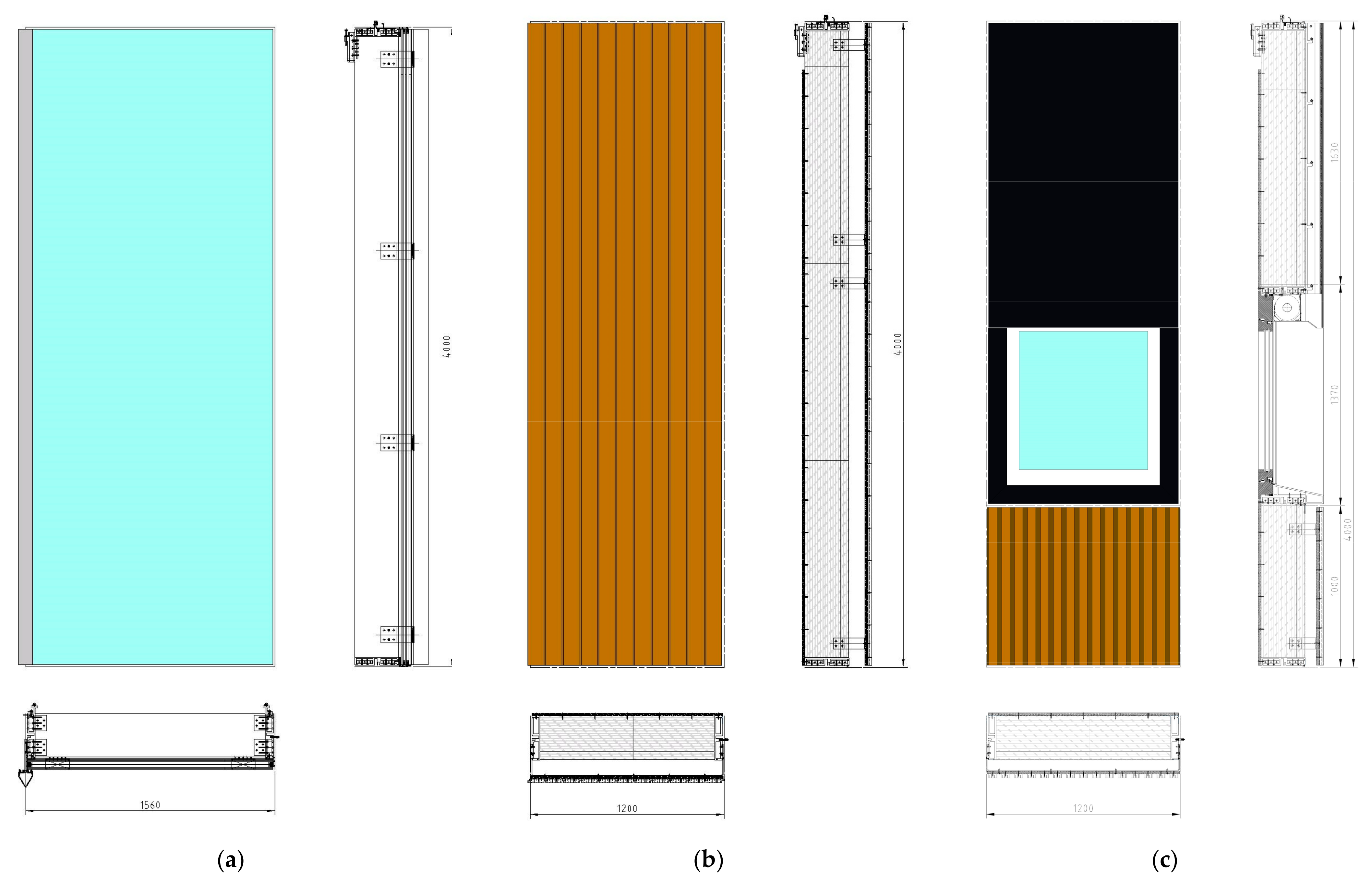
- Design a bio composite-based curtain wall façade system based on technical and normative requirements for real-case applicability in line with the current building envelope standard for curtain wall façade solutions. The design should support the development of multiple façade module typologies with different building envelope targets: (1) vision façade module, (2) opaque façade module, (3) window/opaque façade module.
- Validate with mechanical, thermal, and acoustic simulations the bio-based façade system modules to demonstrate compliance with the normative.
- Identify testing activities in manufacturing and lab environments to validate the feasibility of manufacturing and integrating components in façade system modules.
2. Materials and Methods
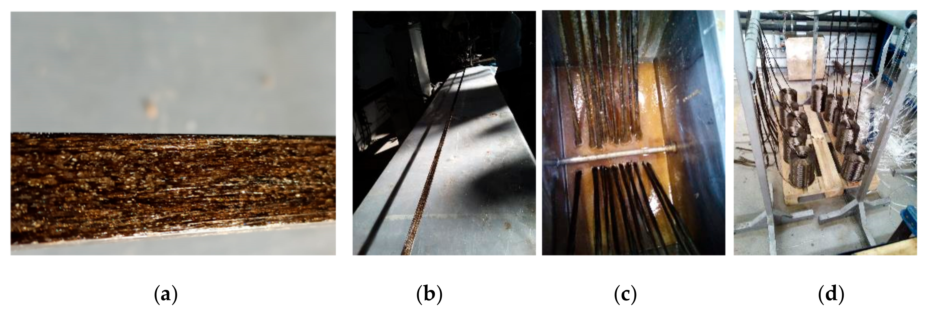
- Analysis for the selection of bio-based and alternative components for façade system module—Bio-based and less environmentally impactful alternative technologies were identified for their potential to meet façade design objectives and minimize carbon footprint. Components with the most significant environmental impact, such as frame profiles, insulation, and tightness system, were evaluated. The rise in eco-conscious practices has promoted the substantial research, development, and commercialization of bio-composites as sustainable alternatives [34]. To work for the Basajaun façade system, bio-composite materials must have advanced mechanical properties through the use of eco-friendly elements like bio-resin and wood. This progression encompasses meticulous raw material analysis, balanced composition, and comprehensive testing. The process involves the selection and evaluation of bio-based polyester and resin, preparation of fibers, pultrusion trials, initial flame retardancy tests, and mechanical characterization. Pultrusion emerges as a cost-effective and competitive method, transforming thermoset matrix and reinforcement into a consistent composite profile. The process involves die definition, impregnated fibers, curing, and cutting, ensuring a competitive edge in composite manufacturing [35,36]. The design supports the standardization and industrialization of multiple façade typologies. The following activities were conducted to achieve the result of designing a bio-based profile for the façade module system.
- ⚬
- Selection and evaluation of bio-based polyester,
- ⚬
- Resin selection and preparation,
- ⚬
- Preparation of fibers,
- ⚬
- Pultrusion trials,
- ⚬
- First flame retardancy tests,
- ⚬
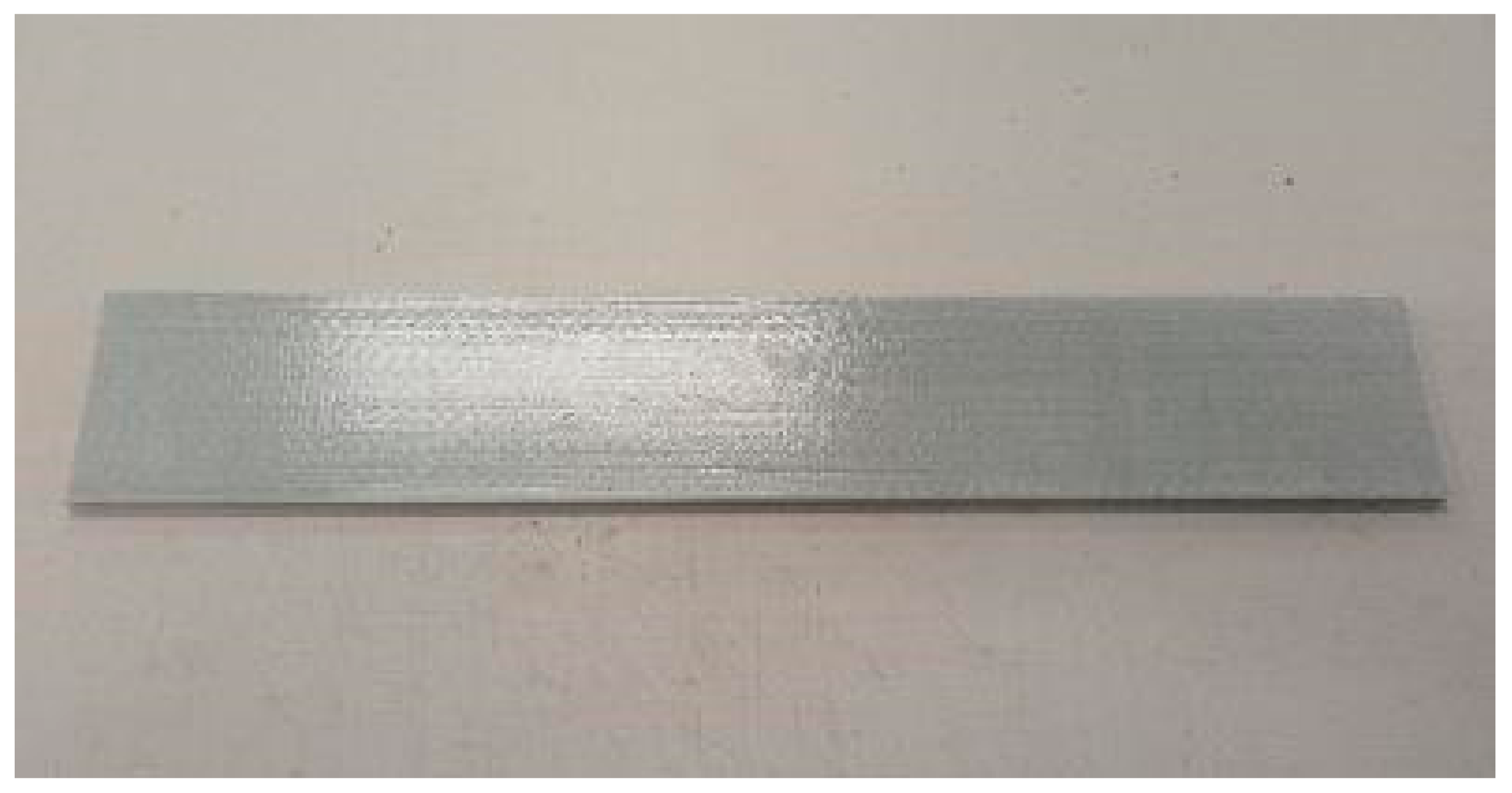
- Mechanical characterization profiles obtained,
- ⚬
- Bio-composite profile for façade system design.
- Identification of façade requirements—Requirements to design the façade for a real-market application were defined. The requirements were identified based on the normative standards in curtain wall façade and real case studies applications adopted as validation simulations for European applications. Due to the evolution and research conducted in the design phase, the final design of the façade optimized the number of system components, unit typologies, and dimensions. Based on the bio-composite material implementation activities, the bio-composite profile was designed to guide the framework of the Basajaun façade system. While curtain façade technology is a mature market for aluminum profiles, the utilization of pultrusion is far from being adopted for building envelopes, and specific requirements must be considered. Preliminary characteristics were considered to start designing the façade system, and Table 1 summarizes the main aspects to be considered for the utilization of the bio-composite profile. In particular, the primary considerations are as follows:
- ⚬
- Simple shape—The pultrusion process needs a more straightforward shape than other manufacturing processes (e.g., extrusion is a typical manufacturing process for aluminum profile), and this requires the profile to have a standard thickness and the absence of notches for fixing (specific corner connectors are needed).
- ⚬
- Mold cost—molds of a significant dimension for the pultrusion process for each profile (mullion, male transom, female transom) are expensive, and the three profiles should be designed as a single shape with a smaller profile for the male transom.

| Bio-Composite Manufacturing Components | Bio-Composite Profile Requirements | Basajaun Profile Design |
|---|---|---|
| Pultrusion activity | The maximum length of the profile is 4 m | Maximum façade height is 4 m |
| Low tolerance during the pultrusion | Simple and reduced activities for cutting and machining | |
| Sharp or rounded corner for the bio-composite profile | ||
| Thickness and dimensions | ||
| Molds | High time-consumption for the mold creations | Unique mold for multiple profiles and accessories for transoms and connection |
| Expensive mold creation | ||
| A simple mold shape is required | Feasibility of the mold geometry needs to be checked | |
| Impossibility of manufacturing notches | ||
| Bio-composite material | Low UV resistance to be protected by façade components | |
| Test compatibility with silicones and sealants |
- Façade System Design—An iterative design process was implemented to refine the façade system configuration to guarantee component integration, off-site production principles, and reduced on-site activities. From the early stages, the design and requirements for the pilot buildings (test for façade applicability in real building cases) are strategic to satisfy different geo-clustering, architectural design, and project specifications. In particular, the following points are drivers: (1) the façade architectural design is crucial for product acceptability in the market, and requests made by architects, designers, and customers have a relevant role in the overall acceptance. (2) Performance definition: the performances are the key elements that need to be considered and balanced in façade engineering. They are related to local norms (acoustic, thermal) and also related to the overall façade performances to be achieved (air and water tightness, impact resistance). The above considerations address implementing a curtain wall system for both opaque and vision façade module systems by introducing bio-based components. Integrating male/female transoms enhances prefabrication, facilitating efficient on-site installation with improved air and water tightness. Mechanical improvements in the bio-composite profile accommodate higher loads, refining façade, and unit typologies. Moreover, an external off-site fin installation reduces on-site tasks for vision façades, while removable external cladding in opaque façades allows for off-site installation and on-site maintenance or finishing adjustments. Because of this analysis, the Basajaun façade system is defined based on requirements and on market standards for the curtain wall façade related to the specific norms of reference. Indeed, applying the Basajaun façade in demo buildings is the first validation on the market in real buildings with their stakeholders.
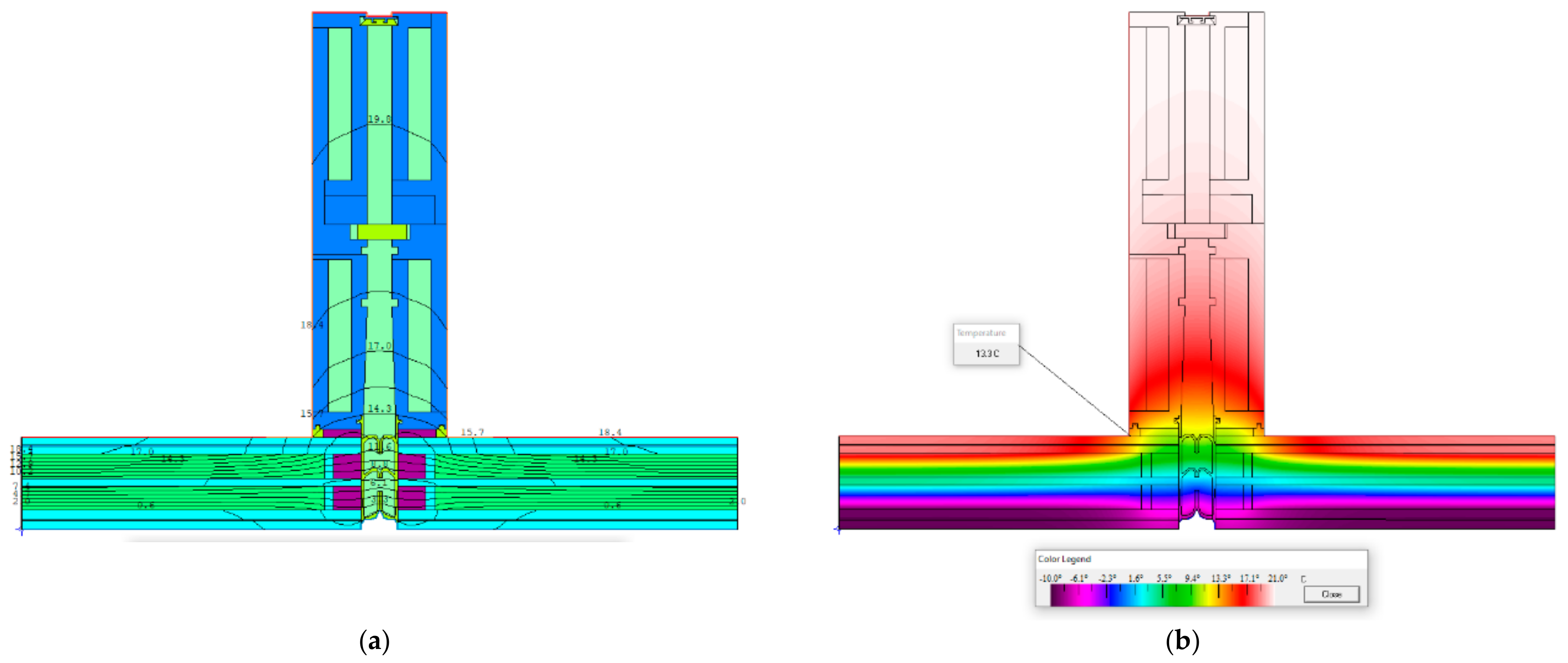
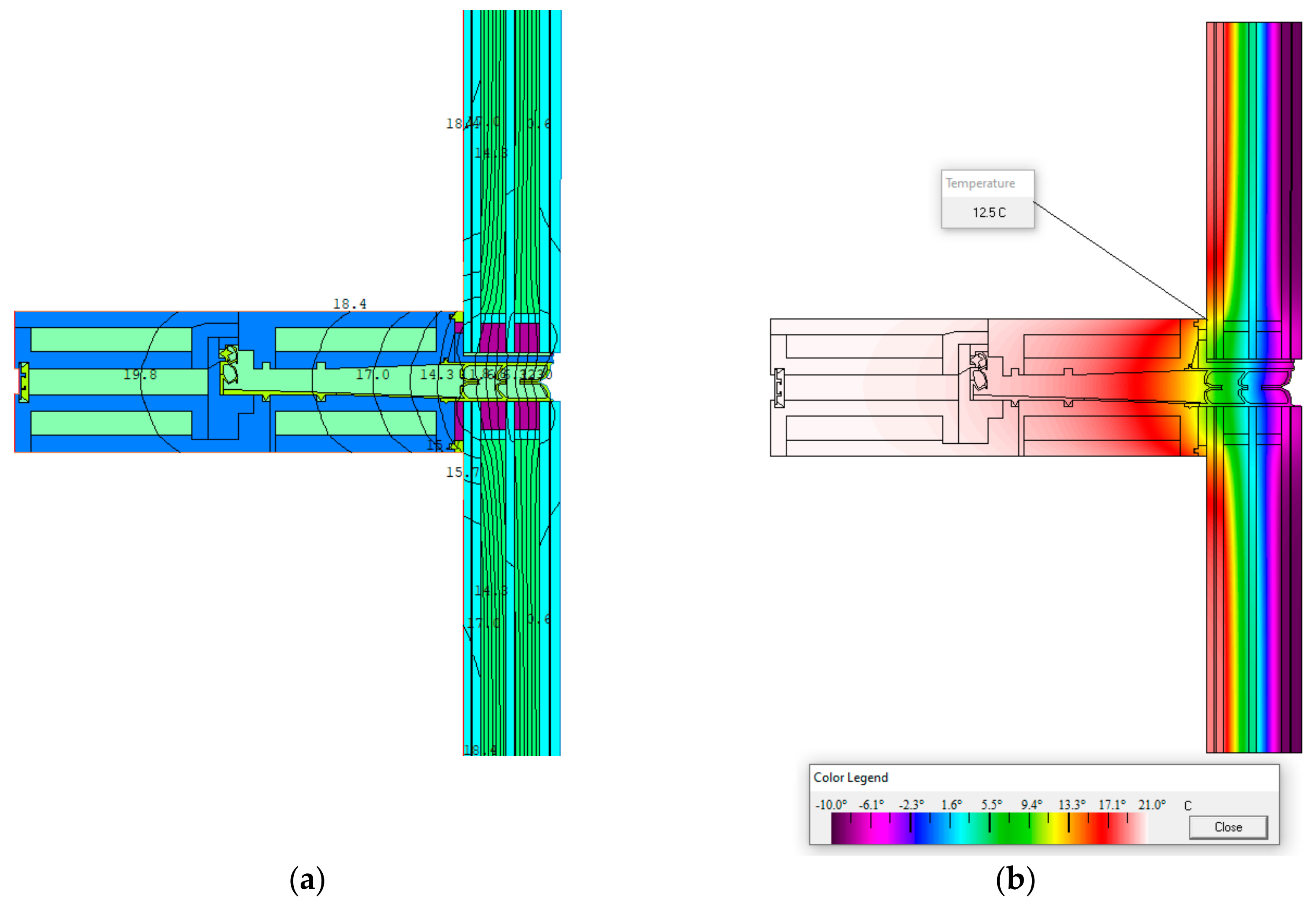
- Façade system design validation—An iterative process to simulate façade behavior to identify mechanical, thermal, and acoustic behaviors. This phase is a desk validation of the façade design and its components before the manufacturing. Based on the identified requirements, a set of validation tests during the integration of the components was defined at different stages of the development of the façade systems. Table 3 outlines the activities deployed for validation during design activities.
| Validation | Test Conducted | |
|---|---|---|
| Thermal behavior (EN 13788) [41] | EN 9869: 2014 [39] | Simulation |
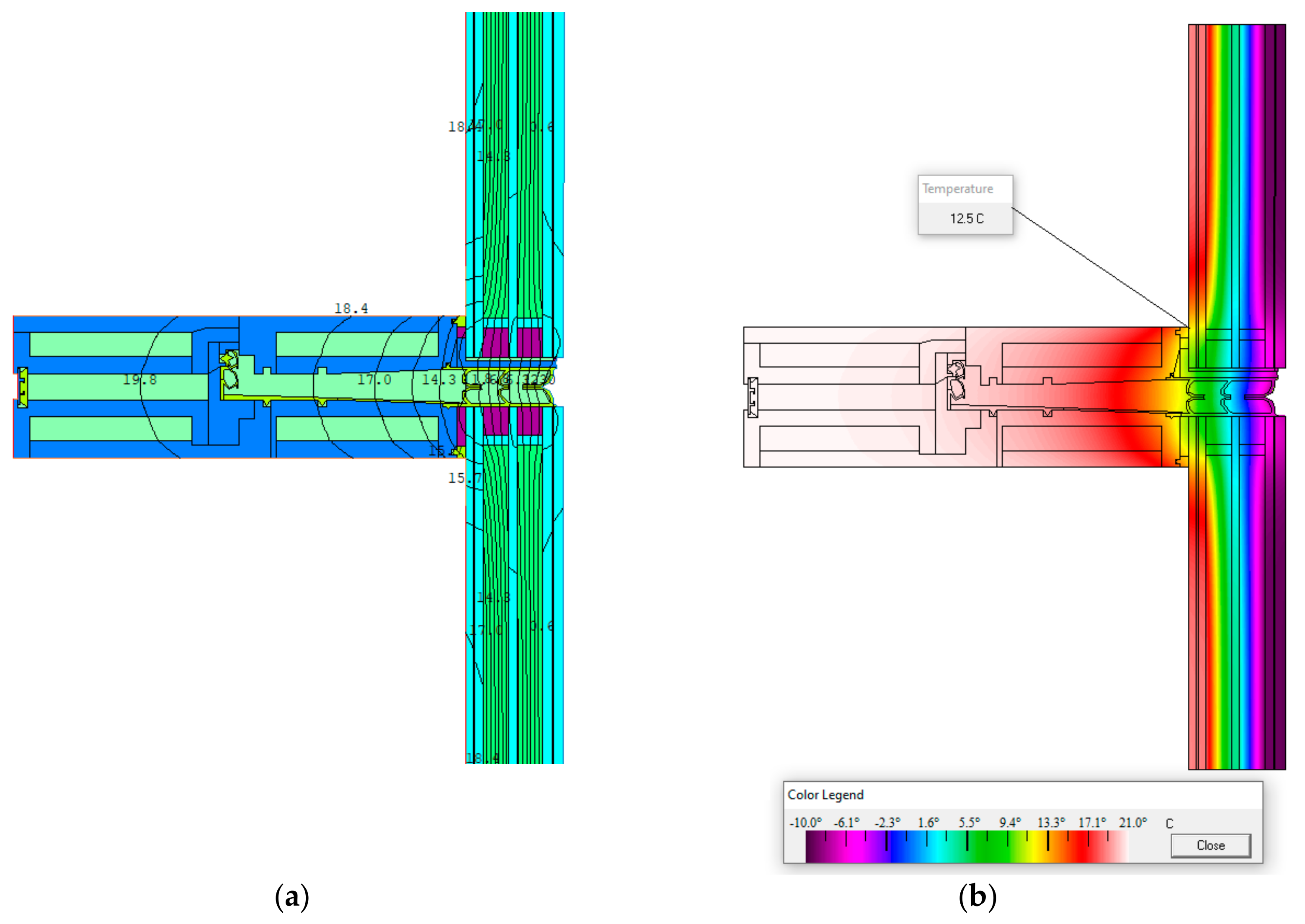
| Heat bridges and condensation risks | EN 15026:2007 [40] | Simulation |
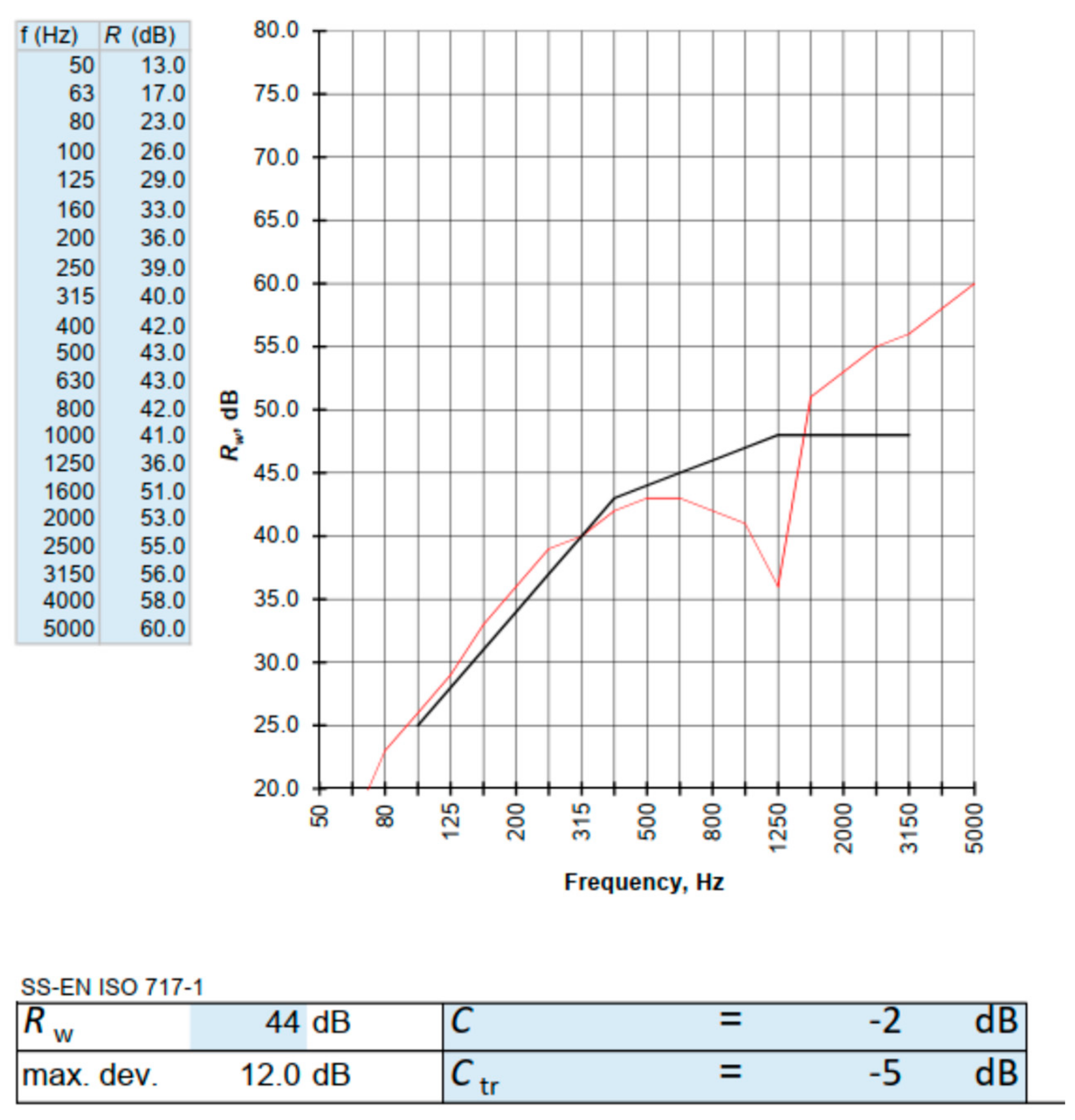
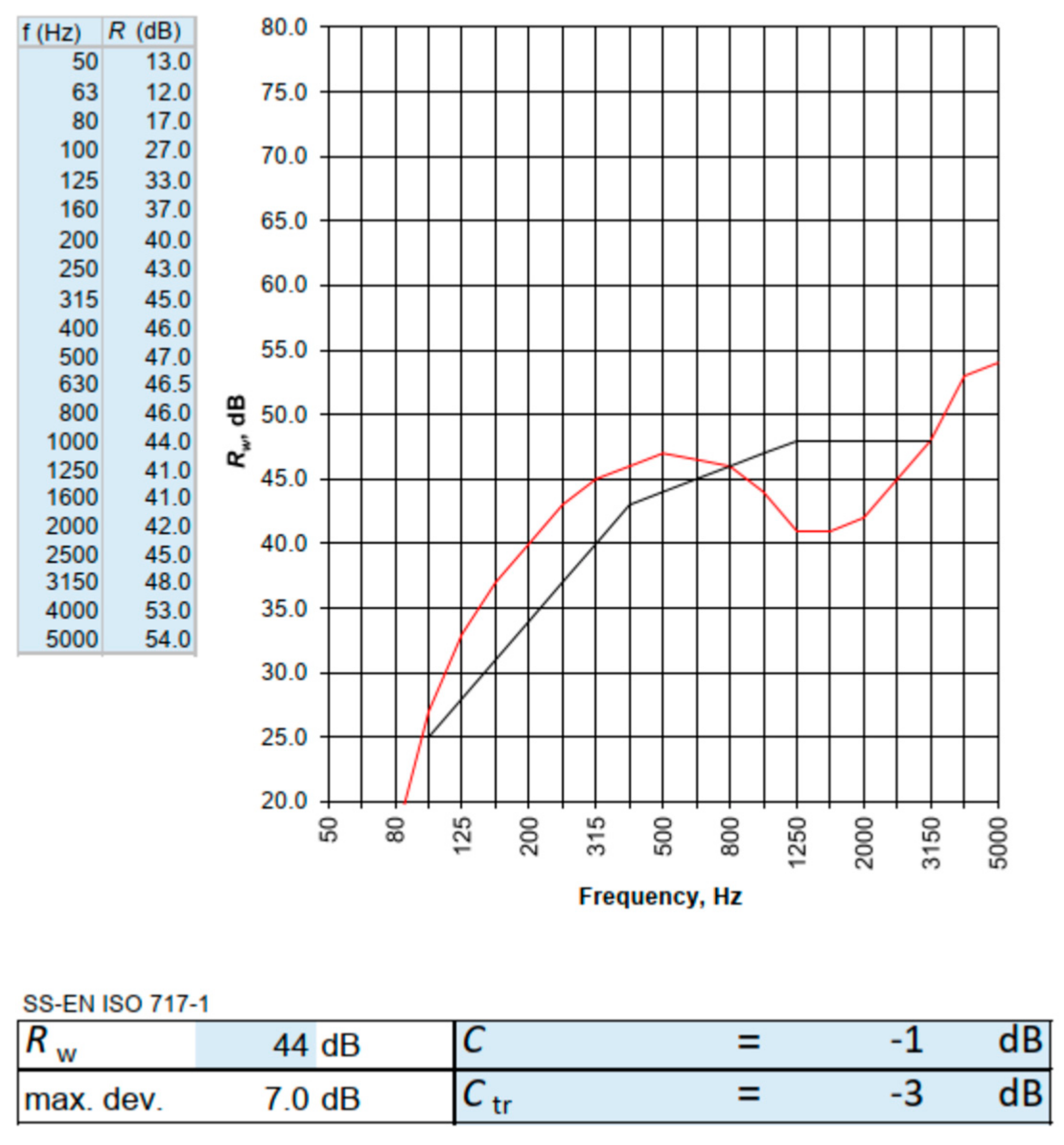
| Acoustic insulation | EN 717-1:2020 [38] | Simulation |
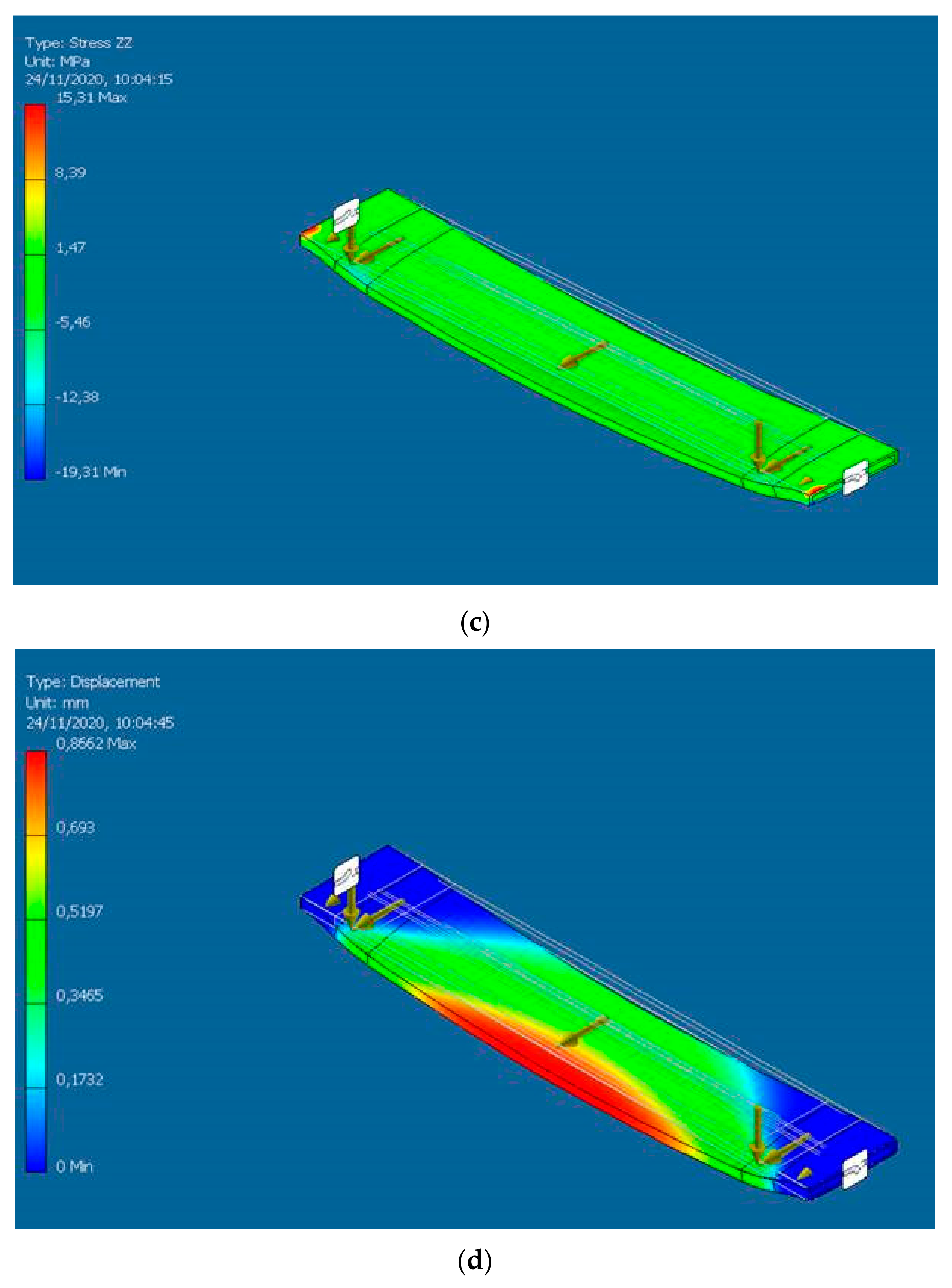
- Glass weight: 25 kN/m3 × 0.029 m × 1.56 m × 3.85 m/2 supports = 2.18 kN at l/10 ends of the bottom transom.
- Façade wind load (suction): −3.5 kN/m2. The wind load is uniformly distributed over the entire glass surface.
- The value of the linear live load is 1.0 kN/m at a 1.20 m height from the bottom edge.
- ULS1 (Ultimate State Limit): 1.35 self-weight load + wind load (suction) × 1.5 + horizontal live load × 1.5 × 0.7.
- ULS2 (Ultimate State Limit): 1.35 self-weight load + wind load (suction) × 1.5 × 0.6 + horizontal live load × 1.5
- SLS1 (serviceability limit state): self-weight load + wind load (suction) + horizontal live load × 0.7.
- SLS2 (serviceability limit state): self-weight load + wind load (suction) × 0.6 + horizontal live load.
- The outcomes of the experimental façades developed in the OSIRYS project [31] were used as a starting point for investigating the bio-composite profiles for façades and the development of an industrialized solution for market integration. On the other hand, the RenoZEB project [43,44] outcomes were used as a starting point for investigating the adoption of membranes and tape alternatives to metal sheets within the curtain wall façade market.
- Real-case demo buildings were adopted, one in Jyväskylä, Finland, and one in Bordeaux, France, to define some pilot cases for façade requirements identification in two climate conditions [45].
- Software adopted for simulations:
- ⚬
- Mechanical simulations with AUTODESK INVENTOR PROFESSIONAL 2020.
- ⚬
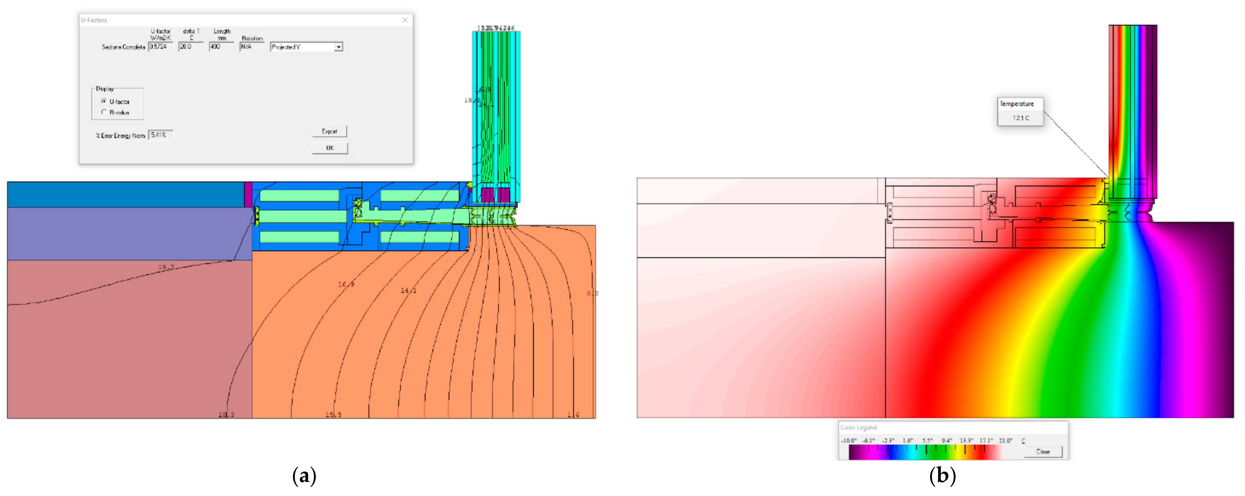
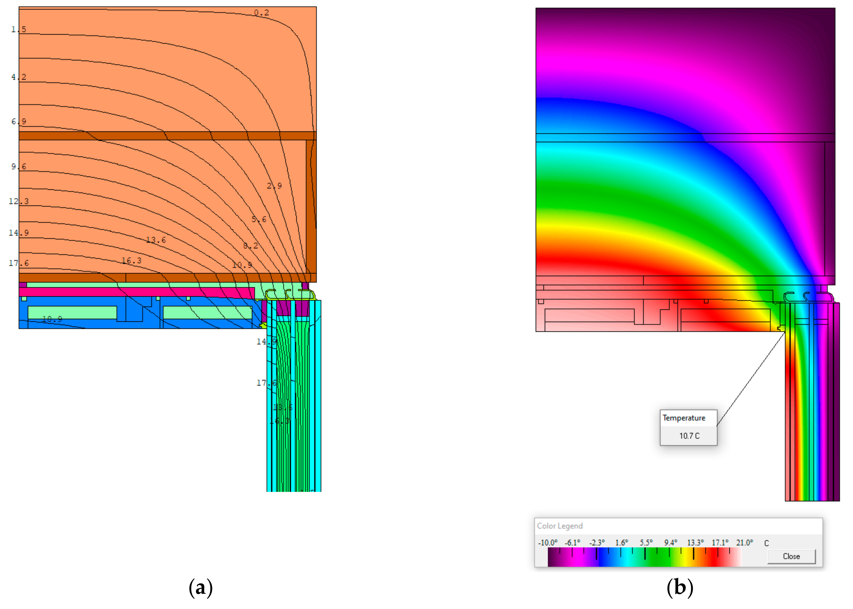
- Thermal simulation with THERM 7.7, following the conventions in EN ISO 10211 [42] and conductivity values as reported in Table A1, reference to Appendix A.
- ⚬
- Acoustic simulation based on EN 717-1 [38].
3. Results
3.1. Bio-Based and Alternative Components for Façade System Module
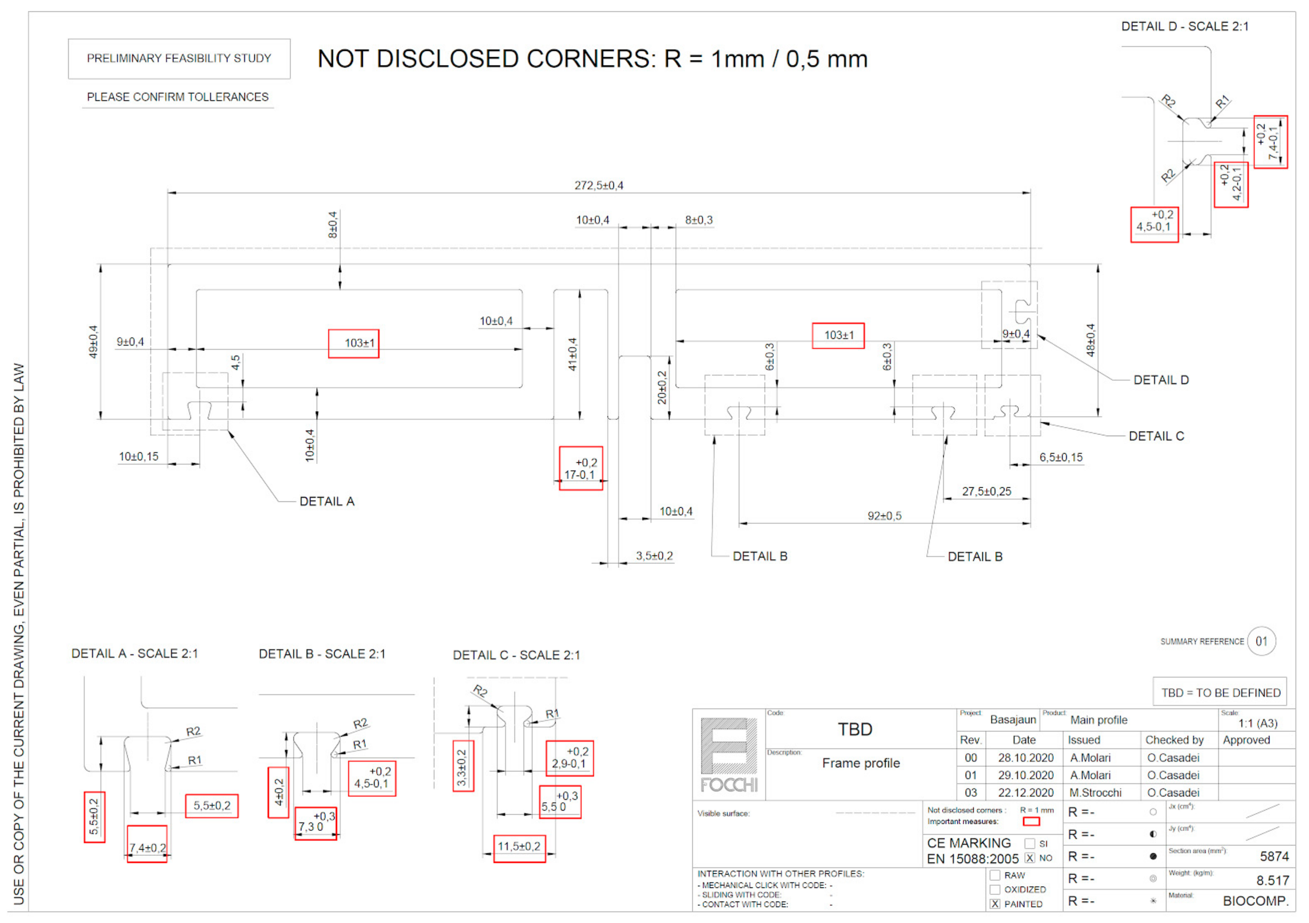
- Frame profile—the conventional on-market curtain wall façade adopts an aluminum profile, with a European average of 36% of recycled content and an embodied carbon of about 44.03 kgCO2eq/mL, while the bio-composite pultruded profile has 26.80 kgCO2eq/mL of embodied carbon.
- Insulation—the conventional on-market curtain wall façade adopts rock wool with an average A1–A5 GWP from EPDs of about 45.00 kgCO2eq/m3, while the wood fiber insulation used in Basajaun has an A1–A5 GWP of 1.63 kgCO2eq/m3 (biogenic carbon = 261.00 kgCO2eq/m3) certified by an EPD [49]. Insulation panels that guarantee the same thermal resistance were compared.
- Tightness layer and stiffness layer—the conventional on-market curtain wall façade adopts silicones, sealants, and aluminum sheets with an estimated embodied carbon of about 37.74 average kgCO2eq/m2 for an opaque façade module, while the membranes, tapes, and plywood implemented have an estimated embodied carbon of about 5.41 kgCO2eq/m2 of an opaque façade module (biogenic carbon = 15.10 average kgCO2eq/m2).
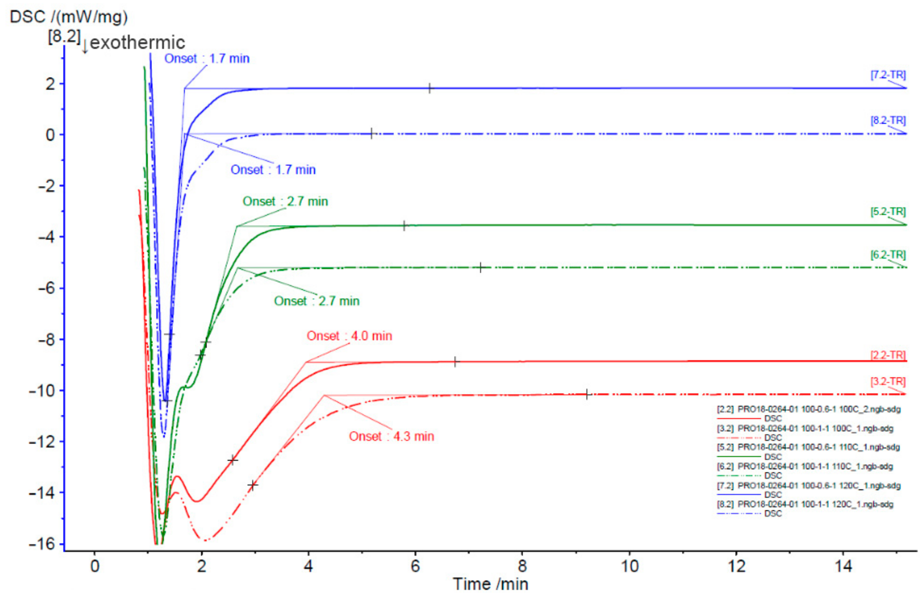
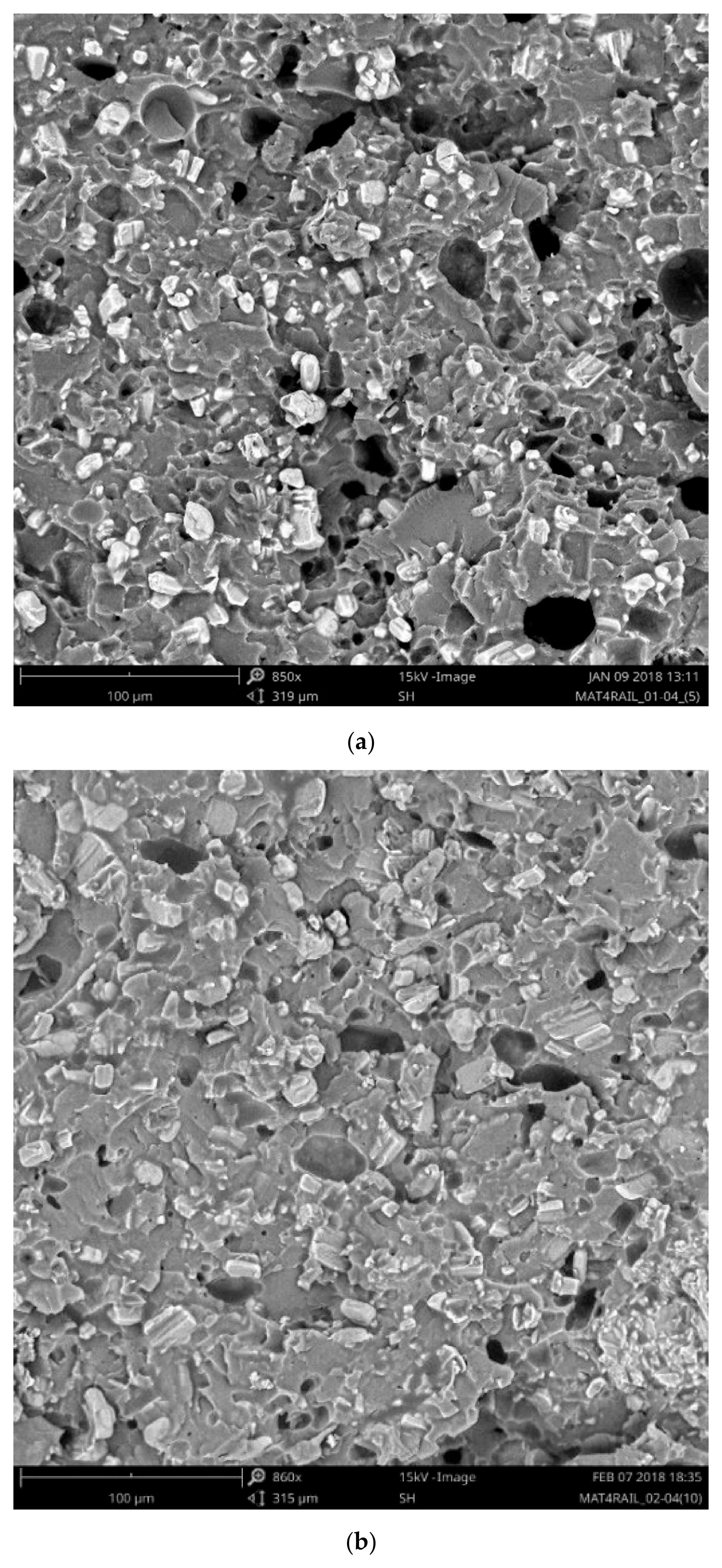
3.1.1. Bio-Composite Frame Profiles
- The catalyst was mixed with resin.
- A hardener and liquid components were added to this mixture.
- Once the mixtures were prepared, they were stirred with the help of a high-speed mixer.
3.1.2. Wood-Based Insulation
3.1.3. Alternatives Seals and Gaskets
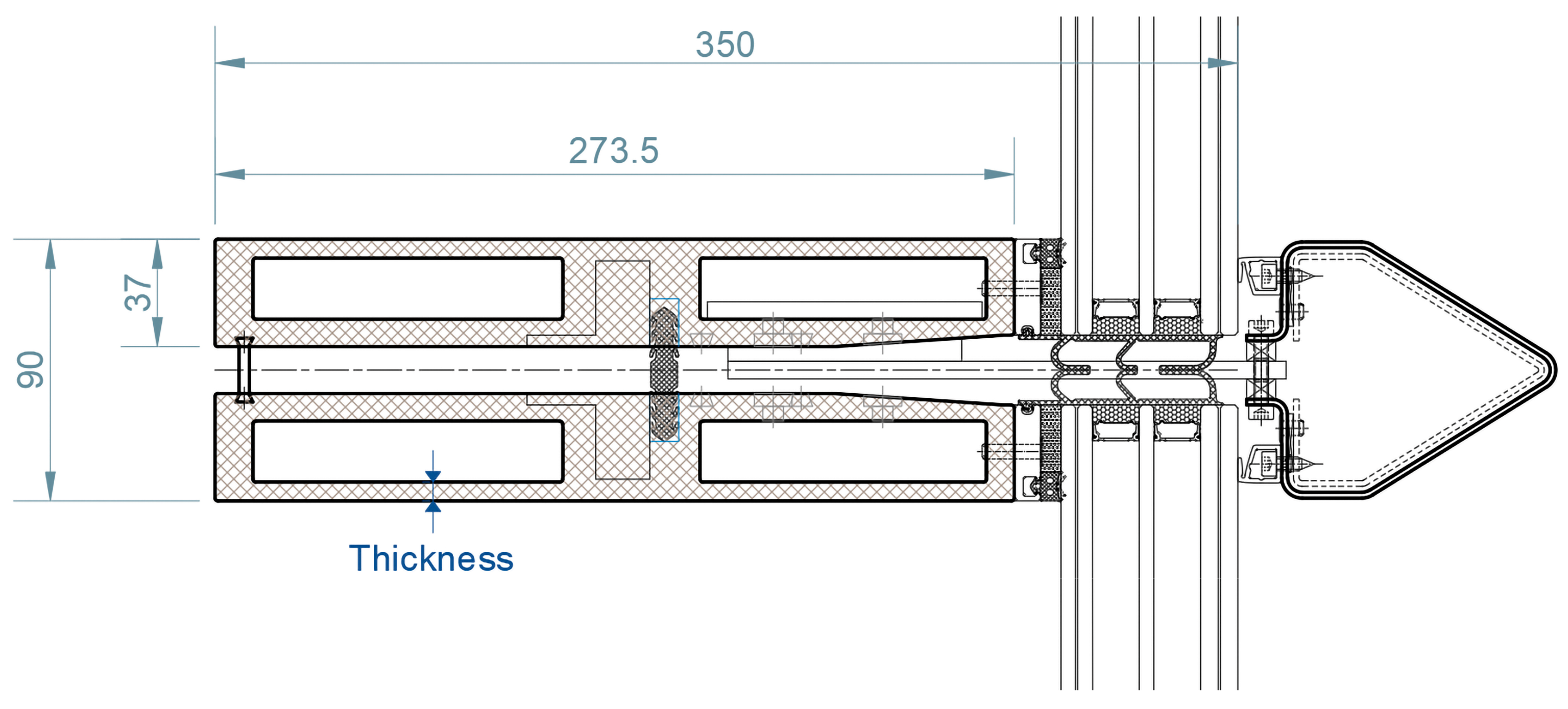
3.2. Bio-Based Façade System Design
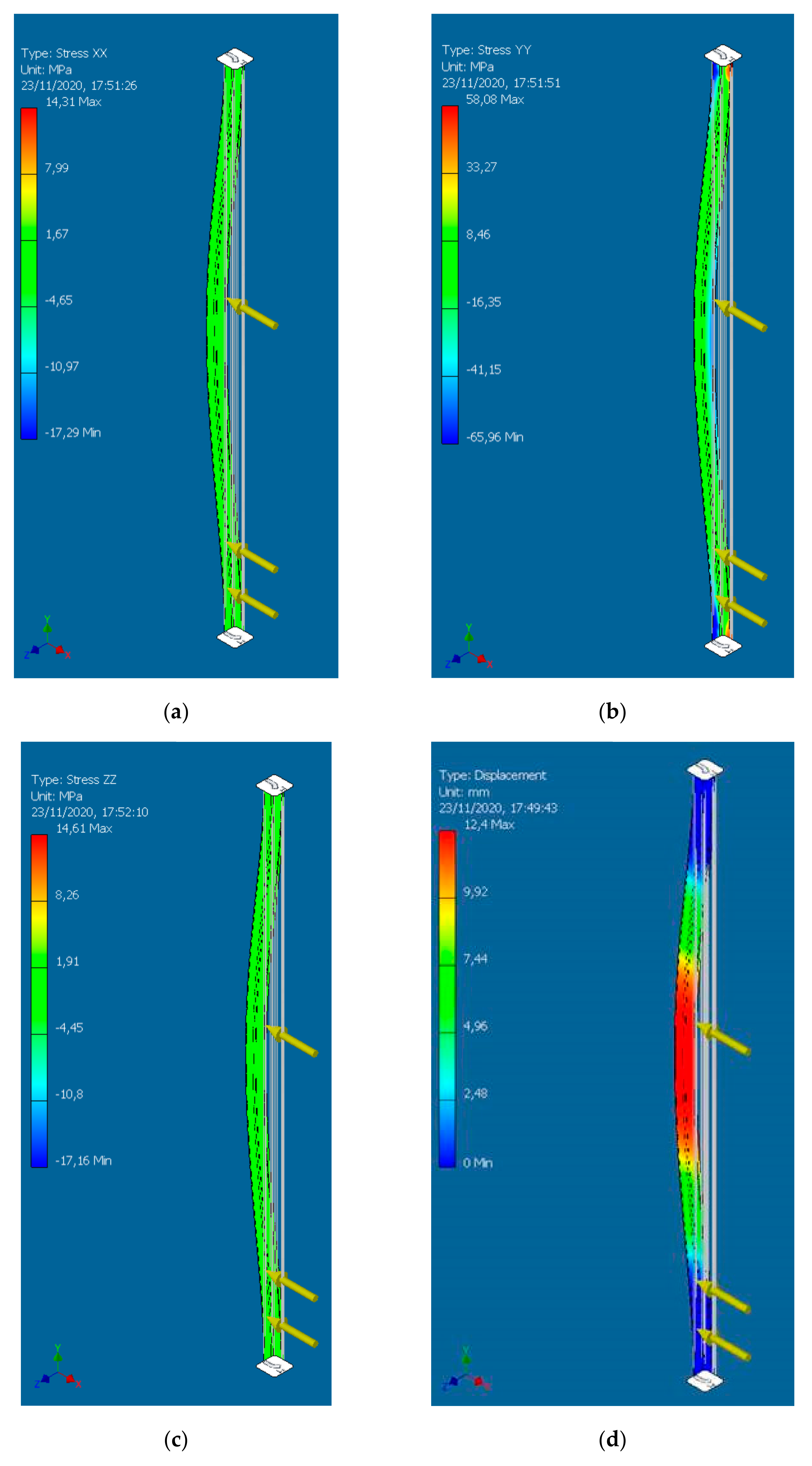
3.2.1. Vision Façade System
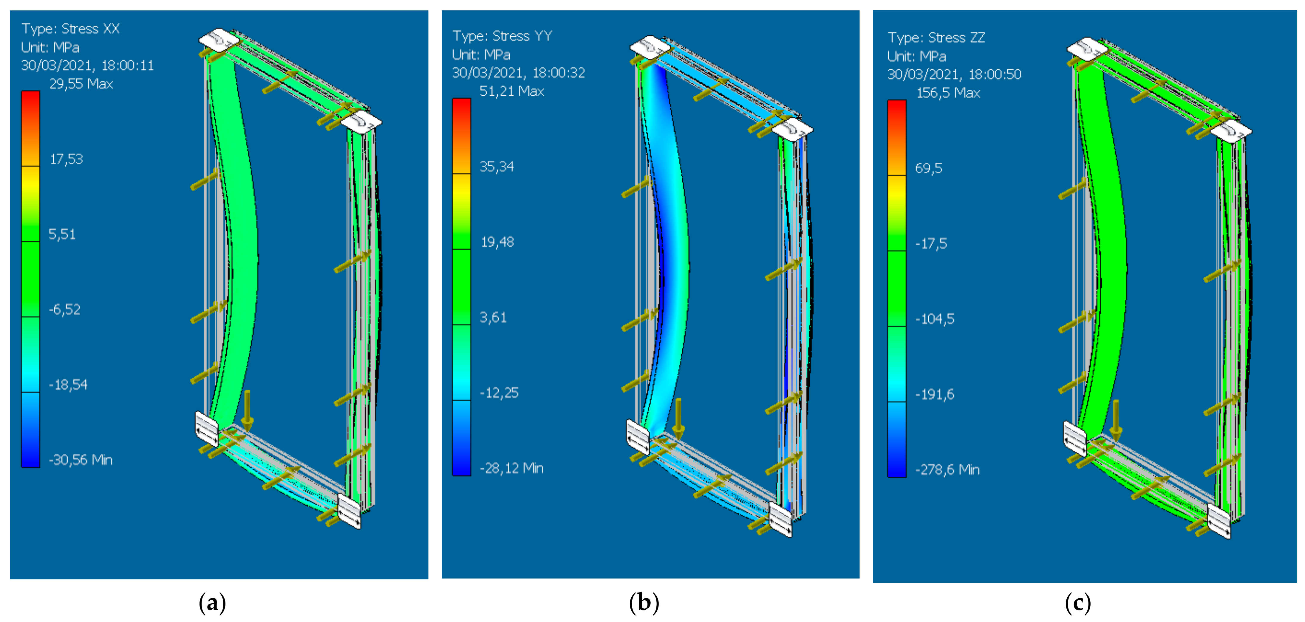
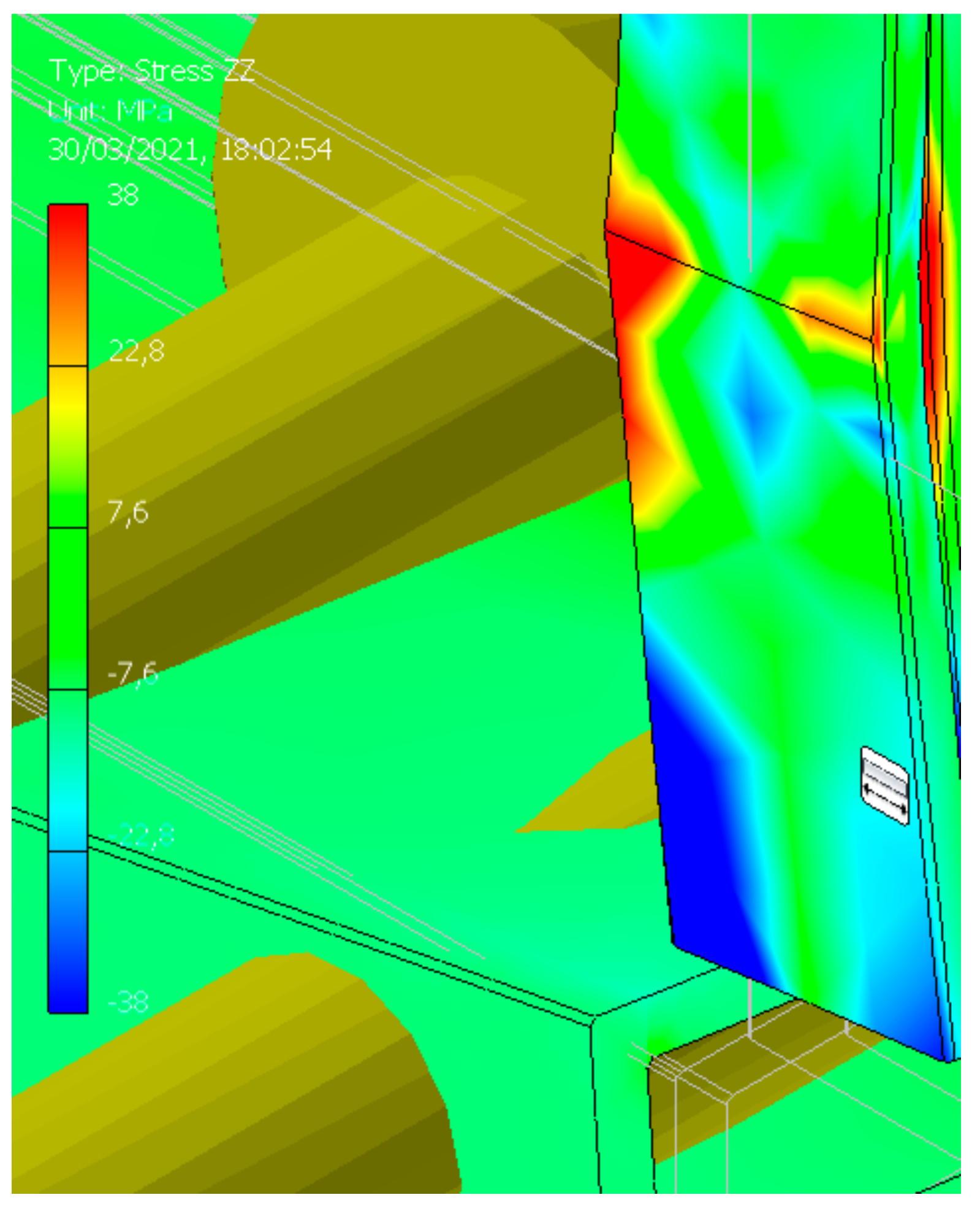
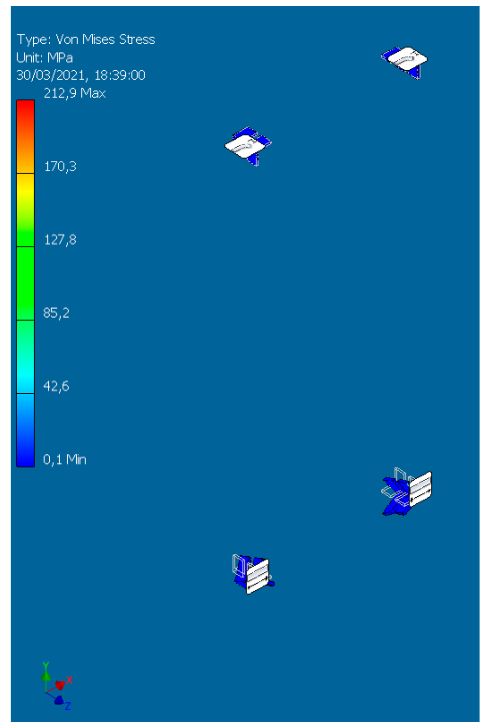
- The perimeter structure stress analysis requested is as follows:
- ⚬
- Stress XX—Permissible Stress: 38 MPa.
- ⚬
- Stress YY—Permissible Stress: 125 MPa.
- ⚬
- Stress ZZ—Permissible Stress: 38 MPa.
- ⚬
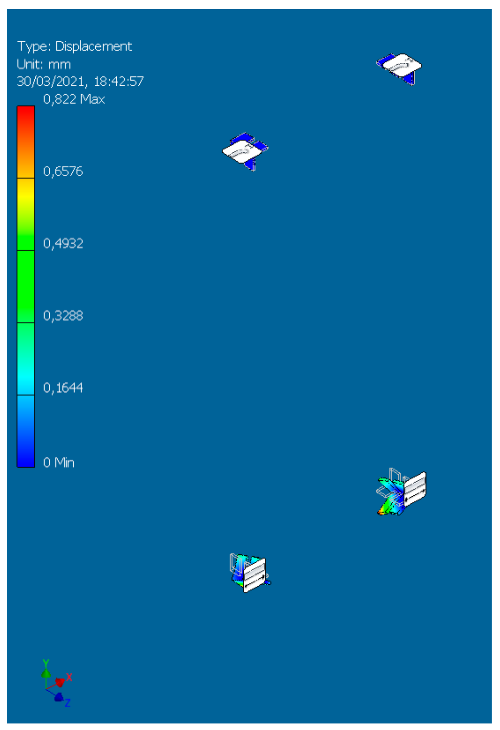
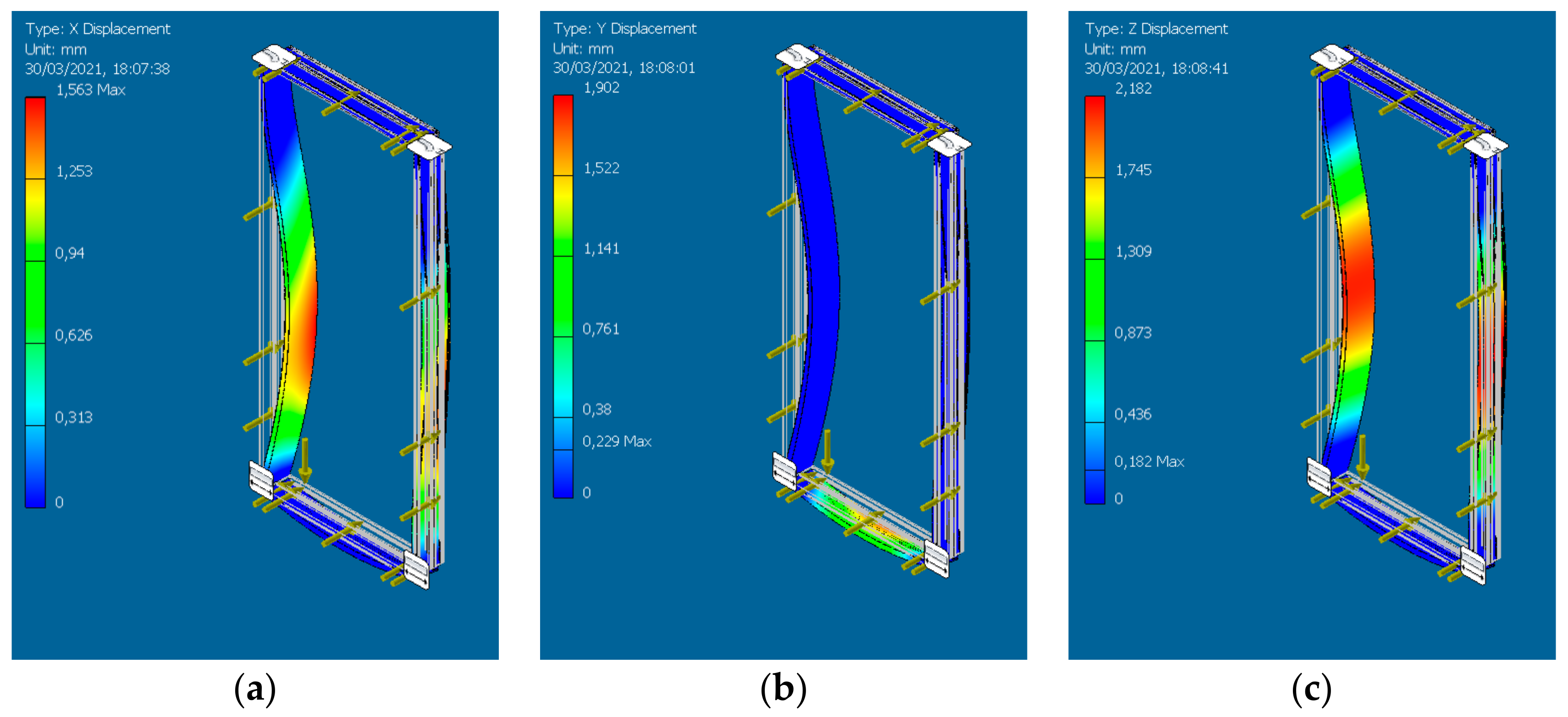
- X Deflection—Max. Deformation < 3850/300 + 5 = 17.83 mm.
- ⚬
- Y Deflection—Max. Deformation < 1560/500 = 3.12 mm.
- ⚬
- Z Deflection—Max. Deformation < 3850/300 + 5 = 17.83 mm.
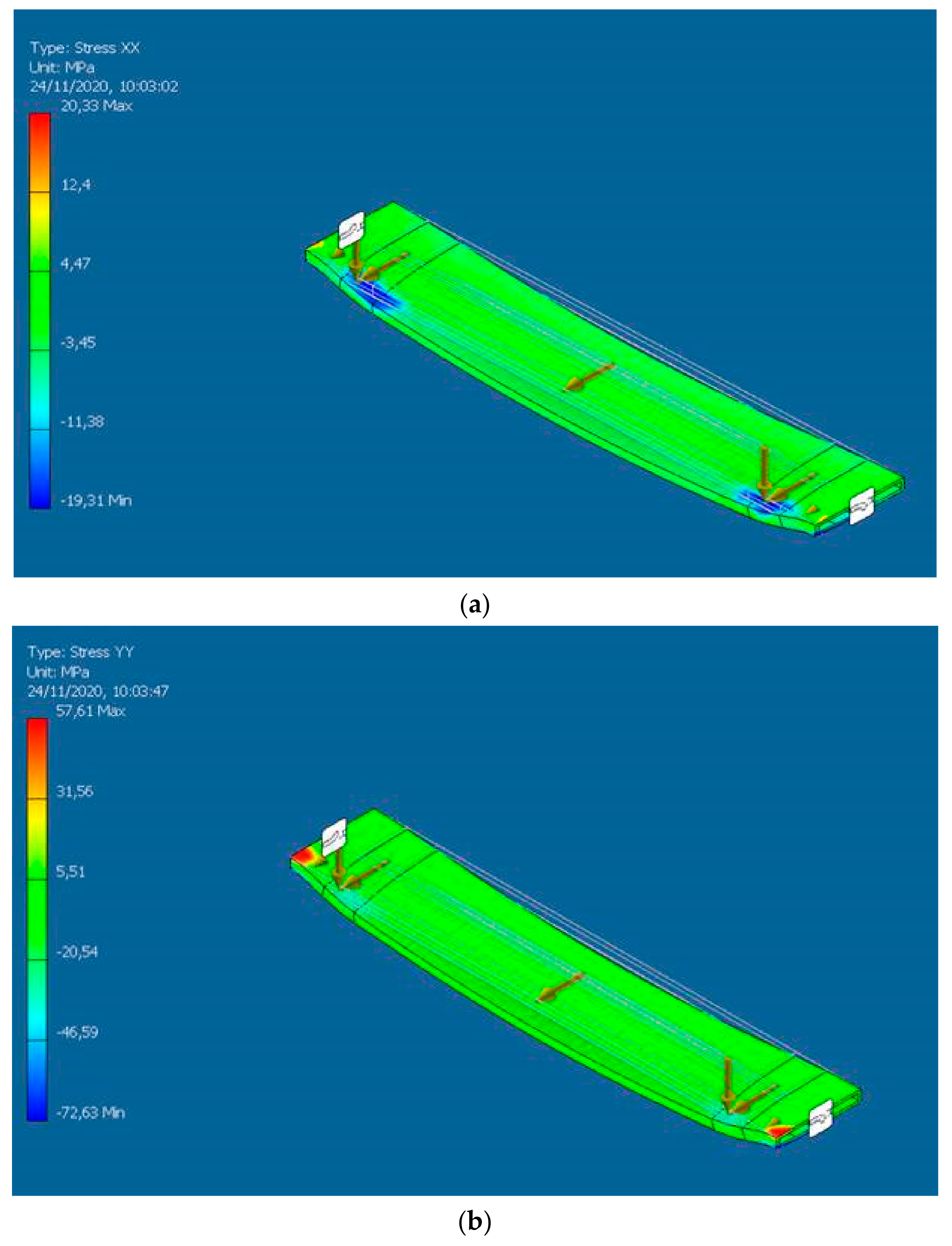
- The cross-member connection stress analysis requested is as follows:
- ⚬
- Stress—Permissible Stress: 227 MPa (250/1.1) Aluminum 6082 T6.
- ⚬
- X Deflection—Max. Deformation < 1 mm.
3.2.2. Opaque Module Façade System
3.2.3. Window/Door Module Façade System
4. Discussion
- Bio-based pultruded profile for curtain wall façade.
- Mechanical characterization: Mechanical characterization in line with curtain wall façade load requirements is achievable. This result is a balance between the formulation of resins and additives adopted, as well as the profile design (minimum thickness of 8 mm).
- Profile shape: The specific design of a profile to comply with the pultrusion process differs from the extrusion adopted in aluminum bars, which can be a critical stage. The profile shapes are acceptable for production, and the grooves make the profile complex in terms of manufacturability, but also, owing to the expertise of the pultruded, it is feasible. Care must be taken when lacing up the rovings for grooves realization in the profile mold.
- Tolerances: Usual tolerances for aluminum profiles are ±0.3/0.4 mm, which is acceptable for the external side but not feasible for internal parts. For bio-composite pultruded profiles, internal cavities require a tolerance of ±1 mm due to the inserts in the mold for their realization. These cavities are prepared with floating inserts, which are not fixed in the tool, and only the material (resin, roving, fabric) keeps them in the right position. Another aspect is the creation of small radii < 1 mm and the lacing up of the rovings to these areas in the profile mold. Notably, larger-curvature radii necessitate simpler gasket designs, which consequently affect the façade system design. The gasket grooves must be carefully designed and validated during initial bar pultrusion activities, and this will be part of the overall validation process for façade bar manufacturing.
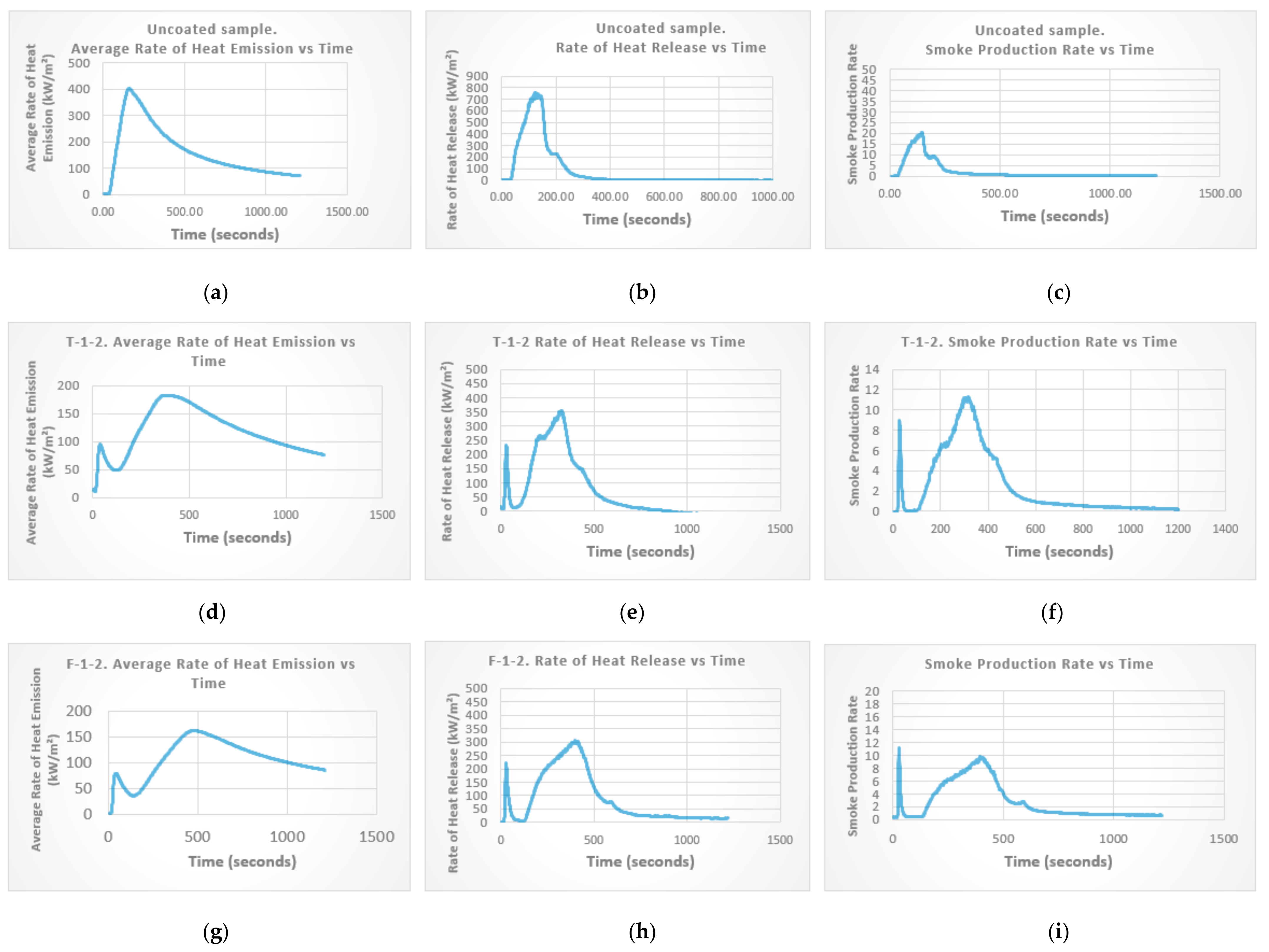
- Fire reaction: Beyond the adoption of fire retardants within the composite solutions, an alternative proposal for an extra coating of one layer of 250 µm or two layers of 650 µm was evaluated. The adoption of this coating would have guaranteed a profile fire reaction in Class A. However, due to the coating dimensions, its adoption needed to be evaluated before the profile design and mold manufacturing to allow for post-pultrusion application.
- Shrinkage: Evaluated by the pultruded manufacturer to have a final profile designed by the façade designer, the adoption of bio-resin replacing conventional resin causes a different material shrinkage. If the shrinkage is significant, the shrinkage value is in the dimension of the production mold.
- Bio-based façade module system design.
- The mechanical simulation for the façade’s bar demonstrates the feasibility of a load stress façade module system. However, the required load capacity of the frame necessitates bars with larger dimensions than extruded aluminum profiles, with limitations on bar lengths. For façade manufacturing reasons, to keep the bar weight below 25 kg, the bar has a maximum length of 4 m. This bar length allows for addressing façade module dimensions. While the longer bar length facilitates façade module design, it also raises issues about its workability during cutting and machining processes for façade manufacturing due to the weight restriction of close to 25 kg. This aspect is a potential limitation for manufacturability and should be investigated during façade manufacturing.
- The results achieved demonstrate that the curtain wall façade system’s alternative components with lower environmental impacts [48] can also be technologically integrated into façade systems. Bio-based profiles, membranes, and tapes for tightness systems have emerged as technological alternatives to metal sheets and sealant systems in façade design. Membranes offer valuable alternatives due to their Class A fire reaction as well as for vapor barrier, water resistance, and wind load capability. However, bio-based profile and wood insulation are not in fire reaction in Class A, and this raises issues on specific market adoption where, as usual, practice or specific norms have request on Class A material. Further investigation is needed into market applications, particularly in markets like the UK, where only Class A insulation is permitted. This limitation, especially following recent tragic fire events in multistorey buildings, warrants further discussion.
- Despite achieving the required thermal transmittance, using a 70 mm insulation layer in the internal wall raises concerns about adopting wood fiber insulation in curtain wall façades. To maintain the same thermal resistance, wider façades must be designed, impacting system size.
- Bio-composite-based curtain walls can be designed to comply with technical and normative requirements for real-world applicability. Additionally, multiple façade system typologies can be designed with the same profile. The overall system design appears to be in line with the requirements of the pilot references. Indeed, based on mechanical, thermal, and acoustic simulations, the bio-based façade system modules demonstrate compliance with the norms.
- The design results only partially validate the façade system, and specific tests are necessary to confirm the adoption of the bio-based profile. Tests must be conducted to verify the adhesion between tape/membrane systems and bio-based profiles. The tests should confirm the compatibility of structural silicone in direct contact with the bio-composite profile for the vision façade module system. This opportunity requires investigation into the adhesion behavior of the bio-composite profile with structural silicone and other sealants to be used in façade manufacturing (vision façade module) and during the installation stage (tightness sealing for curtain wall façade). For a comprehensive demonstration of the façade system in line with the European certification for façade testing, compliance with EN13830 will confirm the air- and water-tightness, wind load resistance, and impact resistance of the façade. Only through these tests can the validation of the designed technological system be confirmed.
5. Conclusions
- Enhancing the proportion of bio-based components in the profiles, with a specific emphasis on the resin content, to contribute to a more sustainable and environmentally friendly product.
- Conducting specific prototyping and test validation to demonstrate how the bio-based façade system achieves the normative standards based on established procedures. The results of the testing activities are published [59].
- Validate the Basajaun façade system design to demonstrate its applicability in pilot buildings with the development of the pilot detail design to investigate the consequences of a real-case design for manufacturing.
- Validate in the production line the façade manufacturing process to demonstrate the feasibility and cost-effectiveness of the tapes/membrane system replacing the metal sheet and sealant as well as to understand the critical aspect for the cutting and machining of pultruded profiles with basalt fibers and their movement operations due to their higher weight than usual aluminum profile.
- Investigate the cost of bio-based façade modules, understand their competitiveness compared to conventional curtain wall façade systems, and determine any potential premium pricing for their adoption.
Author Contributions
Funding
Data Availability Statement
Acknowledgments
Conflicts of Interest
Appendix A
| Material | Thermal Conductivity | Source |
|---|---|---|
| Wood fiber insulation | 0.038 W/mK | Manufacturer |
| Plywood, timber | 0.13 W/mK | EN ISO 10456 [60] |
| Gypsum plasterboard | 0.25 W/mK | EN ISO 10456 [60] |
| Bio-composite | 0.35 W/mK | Assumed |
| EPDM gasket | 0.25 W/mK | EN ISO 10456 [60] |
| Internal seal | 0.35 W/mK | EN ISO 10456 [60] |
| Air cavity (unventilated) | Geometry-dependent | EN ISO 10211 [42] |
References
- Pörtner, H.-O.; Roberts, D.C.; Poloczanska, E.S.; Mintenbeck, K.; Tignor, M.; Craig, M.; Langsdorf, S.; Löschke, S.; Möller, V. Okem IPCC, 2022: Summary for Policymakers. In Climate Change 2022: Impacts, Adaptation and Vulnerability; Contribution of Working Group II to the Sixth Assessment Report of the Intergovernmental Panel on Climate Change; Cambridge University Press: Cambridge, UK; New York, NY, USA, 2022; pp. 3–33. [Google Scholar]
- Adams, M.; Burrows, V.; Richardson, S.; Drinkwater, J.; Gamboa, C.; Collin, C.; Ostenfeld Riemann, L.; Porteron, S.; Qvist Secher, A. Bringing Embodied Carbon Upfront: Coordinated Action for the Building and Construction Sector to Tackle Embodied Carbon; World Green Building Council: Toronto, ON, Canada, 2019. [Google Scholar]
- Ratiarisoa, R.; Magniont, C.; Ginestet, S.; Oms, C.; Escadeillas, G. Assessment of Distilled Lavender Stalks as Bioaggregate for Building Materials: Hygrothermal Properties, Mechanical Performance and Chemical Interactions with Mineral Pozzolanic Binder. Constr. Build. Mater. 2016, 124, 801–815. [Google Scholar] [CrossRef]
- Vinod, A.; Sanjay, M.; Suchart, S.; Jyotishkumar, P. Renewable and Sustainable Biobased Materials: An Assessment on Biofibers, Biofilms, Biopolymers and Biocomposites. J. Clean. Prod. 2020, 258, 120978. [Google Scholar] [CrossRef]
- Jones, D.; Ormondroyd, G.O.; Curling, S.F.; Popescu, C.-M.; Popescu, M.-C. 2—Chemical Compositions of Natural Fibres. In Advanced High Strength Natural Fibre Composites in Construction; Fan, M., Fu, F., Eds.; Woodhead Publishing: Cambridge, UK, 2017; pp. 23–58. ISBN 978-0-08-100411-1. [Google Scholar]
- Leszczyszyn, E.; Heräjärvi, H.; Verkasalo, E.; Garcia-Jaca, J.; Araya-Letelier, G.; Lanvin, J.-D.; Bidzińska, G.; Augustyniak-Wysocka, D.; Kies, U.; Calvillo, A.; et al. The Future of Wood Construction: Opportunities and Barriers Based on Surveys in Europe and Chile. Sustainability 2022, 14, 4358. [Google Scholar] [CrossRef]
- Carcassi, O.B.; Paoletti, I.; Malighetti, L.E. Reasoned Catalogue of Biogenic Products in Europe. An Anticipatory Vision between Technical Potentials and Availability. TECHNE-J. Technol. Archit. Environ. 2021, 22, 63–70. [Google Scholar] [CrossRef]
- Pimponi, D.; Porcari, A.; Airi—Associazione Italiana per la Ricerca Industriale. In Circular Economy in The Building and Construction Sector in Italy: Towards Sustainable Production and Consumption; Mapping of Key Enabling Technologies Innovation Eco-Systems. 2020. Available online: https://www.airi.it/airi2020/wp-content/uploads/2021/06/SocKETs_D1.1_Report_Airi_Final_Website.pdf (accessed on 7 March 2024).
- Fernández Fortunato, E.; Jiménez-Sáez, F.; Hontoria, E. Can Industry Counteract the Ecological Crisis? An Approach for the Development of a New Circular Bioeconomic Model Based on Biocomposite Materials. Sustainability 2023, 15, 3382. [Google Scholar] [CrossRef]
- Kutnik, M.; Suttie, E.; Brischke, C. 10—Durability, Efficacy and Performance of Bio-Based Construction Materials: Standardisation Background and Systems of Evaluation and Authorisation for the European Market. In Performance of Bio-Based Building Materials; Jones, D., Brischke, C., Eds.; Woodhead Publishing: Cambridge, UK, 2017; pp. 593–610. ISBN 978-0-08-100982-6. [Google Scholar]
- Winandy, J.E.; Morrell, J.J. Improving the Utility, Performance, and Durability of Wood- and Bio-Based Composites. Ann. For. Sci. 2017, 74, 25. [Google Scholar] [CrossRef]
- Pokharel, A.; Falua, K.J.; Babaei-Ghazvini, A.; Acharya, B. Biobased Polymer Composites: A Review. J. Compos. Sci. 2022, 6, 255. [Google Scholar] [CrossRef]
- Haraguchi, K. Biocomposites. In Encyclopedia of Polymeric Nanomaterials; Kobayashi, S., Müllen, K., Eds.; Springer: Berlin/Heidelberg, Germany, 2021; pp. 1–8. ISBN 978-3-642-36199-9. [Google Scholar]
- Ahmad, H.; Chhipi-Shrestha, G.; Hewage, K.; Sadiq, R. A Comprehensive Review on Construction Applications and Life Cycle Sustainability of Natural Fiber Biocomposites. Sustainability 2022, 14, 15905. [Google Scholar] [CrossRef]
- Sunthonrvarabhas, J.; Sriroth, K.; Kim, H.-J. Polysaccharide Bio-Based Composites: Nanofiber Fabrication and Application. In Bio-Based Composites for High-Performance Materials; CRC Press: Boca Raton, FL, USA, 2014; ISBN 978-0-429-15616-8. [Google Scholar]
- Zechmeister, C.; Gil Pérez, M.; Dambrosio, N.; Knippers, J.; Menges, A. Extension of Computational Co-Design Methods for Modular, Prefabricated Composite Building Components Using Bio-Based Material Systems. Sustainability 2023, 15, 12189. [Google Scholar] [CrossRef]
- Sandak, A.; Sandak, J.; Brzezicki, M.; Kutnar, A. Biomaterials for Building Skins. In Bio-Based Building Skin; Sandak, A., Sandak, J., Brzezicki, M., Kutnar, A., Eds.; Environmental Footprints and Eco-design of Products and Processes; Springer: Singapore, 2019; pp. 27–64. [Google Scholar]
- Fernando, D.; Navaratnam, S.; Rajeev, P.; Sanjayan, J. Study of Technological Advancement and Challenges of Façade System for Sustainable Building: Current Design Practice. Sustainability 2023, 15, 14319. [Google Scholar] [CrossRef]
- Sandak, A.; Sandak, J.; Brzezicki, M.; Kutnar, A. Designing Building Skins with Biomaterials. In Bio-Based Building Skin; Sandak, A., Sandak, J., Brzezicki, M., Kutnar, A., Eds.; Environmental Footprints and Eco-design of Products and Processes; Springer: Singapore, 2019; pp. 65–97. [Google Scholar]
- EN 13830:2015; Curtain Walling—Product Standard. European Committee for Standardization: Brussels, Belgium, 2015.
- ISO 10077-2:2017; Thermal Performance of Windows, Doors and Shutters—Calculation of Thermal Transmittance—Part 2: Numerical Method for Frames. ISO: Geneva, Switzerland, 2017.
- Juaristi, M.; Sebastiani, I.; Avesani, S. Timber-Based Façades with Different Connections and Claddings: Assessing Materials’ Reusability, Water Use and Global Warming Potential. J. Facade Des. Eng. 2022, 10, 71–86. [Google Scholar] [CrossRef]
- Li, Y.; Chen, L. Investigation of European Modular Façade System Utilizing Renewable Energy. Int. J. Low-Carbon Technol. 2022, 17, 279–299. [Google Scholar] [CrossRef]
- Machado, N.; Morioka, S.N. Contributions of Modularity to the Circular Economy: A Systematic Review of Literature. J. Build. Eng. 2021, 44, 103322. [Google Scholar] [CrossRef]
- Roxas, C.L.C.; Bautista, C.R.; Dela Cruz, O.G.; Dela Cruz, R.L.C.; De Pedro, J.P.Q.; Dungca, J.R.; Lejano, B.A.; Ongpeng, J.M.C. Design for Manufacturing and Assembly (DfMA) and Design for Deconstruction (DfD) in the Construction Industry: Challenges, Trends and Developments. Buildings 2023, 13, 1164. [Google Scholar] [CrossRef]
- López-Guerrero, R.E.; Vera, S.; Carpio, M. A Quantitative and Qualitative Evaluation of the Sustainability of Industrialised Building Systems: A Bibliographic Review and Analysis of Case Studies. Renew. Sustain. Energy Rev. 2022, 157, 112034. [Google Scholar] [CrossRef]
- Savoja, G. Experimentation of Composites Materials Reinforced with Vegetable Fibres for the Construction Sector. TECHNE-J. Technol. Archit. Environ. 2018, 16, 317–324. [Google Scholar] [CrossRef]
- EEB. Circular Economy Principles for the Design of Buildings; EEB Response to Survey; The European Environmental Bureau (EEB): Brussels, Belgium, 2020. [Google Scholar]
- European Parliament and Council. Directive 2010/75/EU of the European Parliament and of the Council of 24 November 2010 on Industrial Emissions (Integrated Pollution Prevention and Control) (Recast) (Text with EEA Relevance); European Union: Brussels, Belgium, 2010. [Google Scholar]
- BASAJAUN. Building A SustainAble Joint between rurAl and UrbaN Areas through Circular and Innovative Wood Construction Value Chains|BASAJAUN Project|Fact Sheet|H2020. Available online: https://cordis.europa.eu/project/id/862942/it (accessed on 11 January 2024).
- Forest Based Composites for Façades and Interior Partitions to Improve Indoor Air Quality in New Builds and Restoration|Osirys Project|Fact Sheet|FP7. Available online: https://cordis.europa.eu/project/id/609067 (accessed on 11 January 2024).
- Arregi, B.; Garay-Martinez, R.; Astudillo, J.; García, M.; Ramos, J.C. Experimental and Numerical Thermal Performance Assessment of a Multi-Layer Building Envelope Component Made of Biocomposite Materials. Energy Build. 2020, 214, 109846. [Google Scholar] [CrossRef]
- Astudillo, J.; González, M.G.; Sacristán, J.; Uranga, N.; Leivo, M.; Mueller, M.; Roig, I.; Langer, S.; Gemignani, G.; Vilkki, M.; et al. New Biocomposites for Innovative Construction Facades and Interior Partitions. J. Facade Des. Eng. 2018, 6, 065–083. [Google Scholar] [CrossRef]
- Zwawi, M. A Review on Natural Fiber Bio-Composites, Surface Modifications and Applications. Molecules 2021, 26, 404. [Google Scholar] [CrossRef]
- Joshi, S.; Chen, X. Time-Variant Simulation of Multi-Material Thermal Pultrusion. Appl. Compos. Mater. 2011, 18, 283–296. [Google Scholar] [CrossRef]
- Jeswani, A.; Roux, J. Modeling of Processing for Slot and Discrete Port Tapered Resin Injection Pultrusion. J. Thermophys. Heat Transf. 2008, 22, 749–757. [Google Scholar] [CrossRef]
- EPD International Library. International EPD System, Stockholm, Sweden. Available online: https://environdec.com/home (accessed on 13 February 2024).
- ISO 717-1:2020; Acoustics—Rating of Sound Insulation in Buildings and of Building Elements—Part 1: Airborne Sound Insulation. ISO: Geneva, Switzerland, 2020.
- ISO 9869-1:2014; Thermal Insulation—Building Elements—In-Situ Measurement of Thermal Resistance and Thermal Transmittance—Part 1: Heat Flow Meter Method. ISO: Geneva, Switzerland, 2014.
- EN 15026:2007; Hygrothermal Performance of Building Components and Building Elements—Assessment of Moisture Transfer by Numerical Simulation. CEN-CENELEC Management Centre: Brussels, Belgium, 2007.
- EN ISO 13788:2012; Hygrothermal Performance of Building Components and Building Elements—Internal Surface Temperature to Avoid Critical Surface Humidity and Interstitial Condensation—Calculation Methods (ISO 13788:2012, Corrected version 2020-05). ISO: Brussels, Belgium, 2012.
- ISO 10211:2017; Thermal Bridges in Building Construction. ISO: Geneva, Switzerland, 2017.
- Pracucci, A.; Vandi, L.; Magnani, S.; Baietta, A.; Casadei, O.; Uriarte, A.; Vavallo, M. Prefabricated Plug-and-Play Unitized Façade System for Deep Retrofitting: The RenoZEB Case Study. Environ. Sci. Proc. 2021, 11, 9. [Google Scholar] [CrossRef]
- Pracucci, A.; Magnani, S.; Vandi, L.; Casadei, O.; Uriarte, A.; Bueno, B.; Vavallo, M. An Analytical Approach for the Selection of Technologies to Be Integrated in a Plug&play Façade Unit: The RenoZEB Case Study. Proceedings 2020, 65, 29. [Google Scholar] [CrossRef]
- Objectives and Impacts. Basajaun-Horizoneu. 2020. Available online: https://basajaun-horizon.eu/ (accessed on 7 March 2024).
- EN 14019:2016; Curtain Walling—Impact Resistance—Performance Requirements. British Standards Institution: London, UK, 2016.
- CWCT Embodied Carbon Committee. Sustainability Guide 01: An Introduction to Sustainability in Façades; Centre for Window and Cladding Technology: Bath, UK, 2021; pp. 1–62. [Google Scholar]
- Morganti, L.; Vandi, L.; Astudillo Larraz, J.; García-Jaca, J.; Navarro Muedra, A.; Pracucci, A. A1–A5 Embodied Carbon Assessment to Evaluate Bio-Based Components in Façade System Modules. Sustainability 2024, 16, 1190. [Google Scholar] [CrossRef]
- Pavatex, S. A/PAVAFLEX Flexible Woodfibre Insulation Material (EPD), Institut Bauen und Umwelt e.V. (IBU): Berlin, Germany, 2014. EPD-PAV-20150043-IBA2-EN. Available online: https://www.lifepanels.com/wp-content/uploads/2022/08/2.-PAVAFLEX-PLUS-Environmental-Product-Declaration-EPD.pdf (accessed on 7 March 2024).
- ISO 137:1975; Wool—Determination of Fibre Diameter—Projection Microscope Method. ISO: Brussels, Belgium, 1973.
- ISO 1889:1987; Textile Glass—Continuous Filament Yarns, Staple Fibre Yarns, Textured Yarns and Rovings (Packages). ISO: Brussels, Belgium, 1987.
- EN ISO 10618:2004; Carbon fibre—Determination of Tensile Properties of Resin-Impregnated Yarn (ISO 10618:2004). ISO: Brussels, Belgium, 2004.
- EN ISO 14125:1998/A1:2011; Fibre-Reinforced Plastic Composites—Determination of Flexural Properties—Amendment 1 (ISO 14125:1998/Amd 1:2011). ISO: Brussels, Belgium, 2011.
- EN 1602:2013; Thermal Insulating Products for Building Applications—Determination of the Apparent Density. ISO: Brussels, Belgium, 2013.
- EN 13171:2012+A1:2015; Thermal Insulation Products for Buildings—Factory Made Wood Fibre (WF) Products—Specification. ISO: Brussels, Belgium, 2015.
- EN 13501-1:2018; Fire Classification of Construction Products and Building Elements—Part 1: Classification Using Data from Reaction to Fire Tests. ISO: Brussels, Belgium, 2019.
- EN 12667:2001; Thermal Performance of Building Materials and Products—Determination of Thermal Resistance by Means of Guarded Hot Plate and Heat Flow Meter Methods—Products of High and Medium Thermal Resistance. ISO: Brussels, Belgium, 2001.
- EN 12086:2013; Thermal Insulating Products for Building Applications—Determination of Water Vapour Transmission Properties. ISO: Brussels, Belgium, 2013.
- Vandi, L.; Navarro Muedra, A.; Larraz, J.A.; Escudero, S.L.D.A.; Pracucci, A.A. Testing Activities for Technological and Normative Validation of Bio-Based Components in Facade System Modules. Preprints 2024, 2024031536. [Google Scholar] [CrossRef]
- EN ISO 10456:2007; Building Materials and Products—Hygrothermal Properties—Tabulated Design Values and Procedures for Determining Declared and Design Thermal Values (ISO 10456:2007). ISO: Brussels, Belgium, 2007.


| Requirement | Vision Module Façade System (Finland) | Opaque and Window Module Façade (France) | Basajaun Façade System Simulation/Test |
|---|---|---|---|
| Airborne sound insulation | Sound insulation R′w ≥ 30 dB. SFS-EN ISO 717-1 [38]. | Acoustic reduction index RA = 31 | RA = 31 Simulation under EN 717-1:2020 [38] |
| Thermal transmittance | U Value of wall/façade: ≤0.17 W/m2K U value of window: ≤1.0 W/m2K | U Value of opaque: = 0.20 W/m2K U Value window: ≤1.3 W/m2K U Value door: ≤0.80 W/m2K | Simulation under EN ISO 10077-2:2017 [21] EN 9869: 2014 [39] EN 15026:2007 [40] |
| Air permeability | A building envelope’s air permeability rate (q50) may be a maximum of 4.0 m3/(h m2). | Air permeability < 0.4 m3(h/.m2) | Air permeability: <0.4 m3(h m2) Test under EN ISO 13830:2005 [20] |
| Liquid Resin Properties | Units | Specifications |
|---|---|---|
| Viscosity (cone and plate @ 25 °C) | dPa.s | 3.9–4.7 |
| Specific Gravity (25 °C) | 1.08 | |
| Volatile Content | % | 35–40 |
| Acid Value | mg KOH/g | 16–20 |
| Stability ¥ when stored in accordance with recommended limits | months | 9 |
| Gel time at 25 °C (1% Catalyst M and 1% Accelerator G) | minutes | 9 to 12 |
| Cast Resin Properties | Units | Specification |
|---|---|---|
| Barcol Hardness (Model GYZJ 934-1) | 36 | |
| Deflection Temperature under load † (1.80 MPa) | °C | 72 |
| Tensile Modulus | GPa | 2.7 |
| Tensile Stress | MPa | 88 |
| Tensile Elongation at break | % | 4.8 |
| Flexural Modulus | GPa | 2.6 |
| Flexural Stress | MPa | 54 |
| Basalt Fibers Properties | Units | Specification |
|---|---|---|
| Single filament diameters:(±1) acc. ISO 137:1975 [50] | [μm] | 13 to 17 |
| Density: | [g/m3] | 2.6 to 2.8 |
| Linear density acc. ISO 1889:1987 [51] | [tex] | 4800 ± 5% |
| Specific tensile strength: acc. DIN ISO EN 10618 [52] | [cN/tex] | 104.6 ± 5% |
| E-Modul acc. DIN ISO EN 10618 [52] | [GPa] | 84.2 ± 5% |
| Linear expansion coeff. | [×10−7/K] | 6 |
| Moisture content: | less than 0.1% | |
| Size content | [%] | 1.0 ± 0.1 |
| Weight of the coil | [kg] | 5 to 10 |
| Stability at tension (20 °C) | [%] | 100 |
| Stability at tension (200 °C) | [%] | 95 |
| Stability at tension (400 °C) | [%] | 82 |
| Thermal limit application | [°C] | 440 |
| Vitrification temperature | [°C] | 1050 |
| Description | Rovings | Mat or Fabric | Fiber | ||||||
|---|---|---|---|---|---|---|---|---|---|
| Tex (gr/km) | No. of Threads or Layers | Gramagge (g/m2) | Effective Width (m) | Weight (g/m) | Density (g/cm3) | Volume (cm3/m) | Fraction V. Local | Occupied Section (cm2) | |
| Roving (basalt fiber) | 4800 | 20 | 96 | 2.65 | 36.23 | 0.55 | 0.66 | ||
| Total | 96 | 36.23 | 0.66 | ||||||
| Percentage of mold filling: occupied section/mold section × 100 | Total | 87.82 | |||||||
| Description | Rovings | Mat or Fabric | Fiber | ||||||
|---|---|---|---|---|---|---|---|---|---|
| Tex (gr/km) | No. of Threads or Layers | Gramagge (g/m2) | Effective Width (m) | Weight (g/m) | Density (g/cm3) | Volume (cm3/m) | Fraction V. Local | Occupied Section (cm2) | |
| Fabric (Glass Fiber) | 2 | 500 | 0.1 | 100 | 2.55 | 39.22 | 0.28 | 500 | |
| Roving (Basalt Fiber) | 4800 | 80 | 384 | 2.55 | 150.59 | 0.55 | 2.74 | ||
| Total | 384 | 150.59 | 4.14 | ||||||
| Percentage of mold filling: occupied section/mold section × 100 | Total | 51.73 | |||||||
| Flammability Rating UL 94 | |||
|---|---|---|---|
| V-0 | V-1 | V-2 | |
| Burning time after flame application (s) | ≤10 | ≤30 | ≤30 |
| Total burning time (s) (10 flame applications) | ≤50 | ≤250 | ≤250 |
| Burning and afterglow times of specimen after second flame application (s) | ≤30 | ≤60 | ≤60 |
| Dripping of burning specimens (ignition of cotton batting) | No | No | Yes |
| Specimens completely burned | No | No | No |
| Description | Classification UL94 |
|---|---|
| Bio-based resin Only resin | Not classifiable |
| Bio-based resin + FR 1 20% | V2 |
| Bio-based resin + FR 1 30% | V0 |
| Bio-based resin + FR 1 40% | V0 |
| Bio-based resin + FR 2 30% | Not classifiable |
| Bio-based resin + FR 2 40% | Not classifiable |
| Bio-based resin + FR 2 50% | Not classifiable |
| Bio-based resin + FR 1 20%+ FR 2 40% | V2 |
| Sample | E | SD | R | SD | %R | SD | Poisson Ratio | SD | Apparent ILSS | SD | Break Mode |
|---|---|---|---|---|---|---|---|---|---|---|---|
| MPa | MPa | % | µ | MPa | |||||||
| Resin with glass fiber cured (2 h 70 °C) | 38,400 | 1920 | 584 | 2.7 | 1.44 | 0.14 | 0.25 | 0.04 | |||
| Resin with basalt fibers with cured cycle (2 h 70 °C) | 39,200 | 1500 | 431 | 73 | 1.11 | 0.16 | 0.07 | 0.06 | 10.7 | 0.8 | simple shear |
| Resin with basalt fibers without cured cycle (20 rovings) | 38,600 | 852 | 378 | 9 | 1.01 | 0.03 | 0.16 | 0.25 | 10.5 | 0.6 | simple shear |
| Resin with basalt fibers and wood particles without cured cycle (13 rovings) | 26,700 | 837 | 426 | 1.6 | 1.6 | 0.08 | 0.24 | 0.14 | |||
| OMIKRON sample (longitudinal direction) | 30,500 [ANM3] | 244 | 453 | 26.1 | 1.5 | 0.1 | −0.04 | 0,05 | |||
| Bio-based resin (Only Resin) | 1870 | 410 | 45.5 | 8.6 | 2.6 | 0.7 | 0.22 | 0.21 | |||
| Bio-based resin (Only Resin) + FR 1 20% | 2160 | 270 | 25.9 | 2.7 | 1.5 | 0.2 | 0.26 | 0.32 | |||
| Bio-based resin (Only resin) + FR 1 30% | 2060 | 319 | 22.1 | 1.3 | 1.6 | 0.4 | 0.35 | 0.14 | |||
| Bio-based resin (Only resin) + FR 1 40% | 2380 | 730 | 18.1 | 1.1 | 0.96 | 0.2 | 0.23 | 0.33 | |||
| Bio-based resin (Only resin) + FR 2 30% | 2750 | 1130 | 13.7 | 3.4 | 0.4 | 0.06 | −0.12 | 0.28 | |||
| Bio-based resin (Only resin) + FR 2 40% | 3000 | 1020 | 17.1 | 2.7 | 0.51 | 0.03 | 0.22 | 0.06 | |||
| Bio-based resin (Only resin) + FR 2 50% | 4160 | 1100 | 20 | 1.6 | 0.43 | 0.01 | 0.74 | 0.17 | |||
| Bio-based resin + FR 1 20% + FR 2 40% | 3550 | 128 | 19.3 | 1.5 | 0.55 | 0.07 | 0.72 | 0.25 | |||
| Test | Flexural Modulus | SD | Flexural Strength | SD | Deflection at Flexural Strength | SD |
|---|---|---|---|---|---|---|
| MPa | MPa | % | ||||
| Flexural properties according to EN ISO 14125 [53] | 32,100 | 792 | 572 | 26 | 6.9 | 0.4 |
| Flexural properties in longitudinal direction (non-standardized tests) | 18,800 | 1580 | 409 | 35 | 2.0 | 0.4 |
| Flexural properties in cross direction (non-standardized tests) | 8790 | 985 | 125 | 4 | 1.6 | 0.2 |
| Maximum Wind Load = 2.00 kN/m2 | |
|---|---|
| Loads: | |
| WL = 2 kN/m2 × 0.79 m × 7.65 m = | 12.1 kN |
| WLult = 1.5 × 12.1 = | 18.13 kN |
| E = 1 kN/m × 0.79 m = | 0.79 kN |
| Eult = 1.05 × 0.79 kN = | 0.83 kN |
| E2 = 1 kN/m × 0.79 m × 0.7 = | 0.553 kN |
| Maximum Wind Load = 2.00 kN/m2 | |
|---|---|
| Loads: | |
| WL = 2 kN/m2 × 0.79 m × 1.58 m = | 2.5 kN |
| WLult= 1.5 × 2.5 = | 3.75 kN |
| DL = 25 kN/m3 × 0.027 m × 7.65 m × 1.58 m/2 Blocks = | 4.1 kN |
| DLult= 1.35 × 4.1 = | 5.51 kN |
| Wood Fiber Insulation Used in Basajuan | Average Rock Wool Products from Supplier A | Average Rock Wool Products from Supplier B | |
|---|---|---|---|
| Gross density (EN 1602) [54] | 55.00 kg/m3 | 72.33 kg/m3 | 80.00 kg/m3 |
| Thermal conductivity (EN 13171) [55] | 0.038 W/(mK) | 0.034 W/(mK) | 0.035 W/(mK) |
| Fire classification (EN 13501-1) [56] | Class E | Euroclass A1 | Euroclass A1 |
| Water vapor resistance | 5 (EN 12667) [57] | Not specified | 1 (EN 12086) [58] |
| Reflective Fire Reaction Vapor Barrier Screen Used in Basajuan | Example of an Average Sheet as Conventional per Façade Module Type A | Example of an Average Sheet as Conventional per Façade Module Type B | |
|---|---|---|---|
| Material | Aluminum—PE-Glass fiber | PET | PUR.PP |
| Fire classification (EN 13501-1) [56] | Class A2-s1, d0 | B-s1, d0 | Class E |
| UV resistance | ✔ | ✔ | ✔ |
| Water impermeability | Class W1 | Class W1 | Class W1 |
| Water vapor transmission (Sd) [m] | 0.08 | 0.02 | 0.14 |
| Tensile strength [N/5 cm] | 3000/3200 | 250/210 | 210/205 |
| Thermal conductivity [W/(m∗k)] | 0.0007 | 0.17 | 0.22 |
| Vapor resistance factor [μ] | 185 | 40 | 200 |
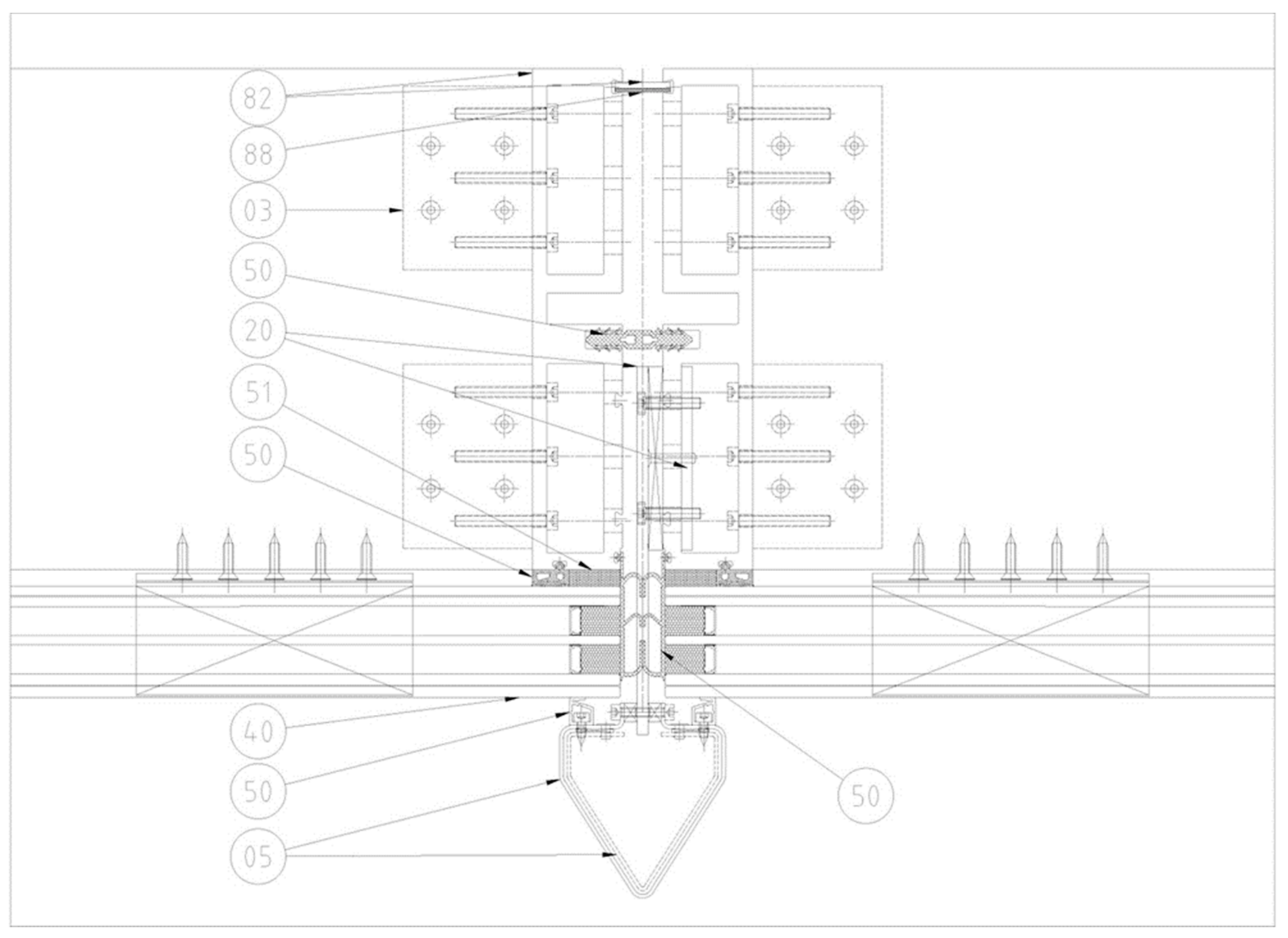
| Figure Code | Layer | Objectives | Characteristics |
|---|---|---|---|
| 03 | Aluminum bracket mill finish | To connect the transoms to the mullions | Structural part |
| 05 | Aluminum sheet | External finishing | - |
| 20 | Stainless steel sheet AISI316 | To connect the external fin to the frame | Structural part |
| 20 | Stainless steel sheet AISI316 | Internal support | Structural part |
| 40 | GL-1 TGU | - | Triple glass unit |
| 50 | EPDM gasket | Second water barrier | - |
| 50 | EPDM gasket | Glass support | - |
| 50 | EPDM gasket | First water barrier | - |
| 50 | EPDM gasket | Finishing gasket | - |
| 51 | Structural silicone black color | To join the glass to the frame | Structural part 9 mm × 27 mm |
| 82 | Bio-composite profile—internal key | To join two units | Thickness 3.5 mm |
| 82 | Bio-composite profile—mullions | To bead the unit load and connect it with the structural slab | Thickness 8/10 mm |
| 88 | Foam rubber | To not vibrate the internal key | - |
| Node | Length m | Area m2 | UTJ W/m2K | UTJ × A W/K |
|---|---|---|---|---|
| Node 1 | 0.9 | 2.498 | 2.253 | 5.630 |
| Node 2 | 0.9 | 0.614 | 2.331 | 1.431 |
| Node 3 | 0.36 | 2.525 | 0.556 | 1.404 |
| Node 4 | 0.30 | 2.304 | 0.521 | 1.201 |
| Node 5 | 0.24 | 2.732 | 0.852 | 2.328 |
| Glass | 44.894 | 0.650 | 29.181 |
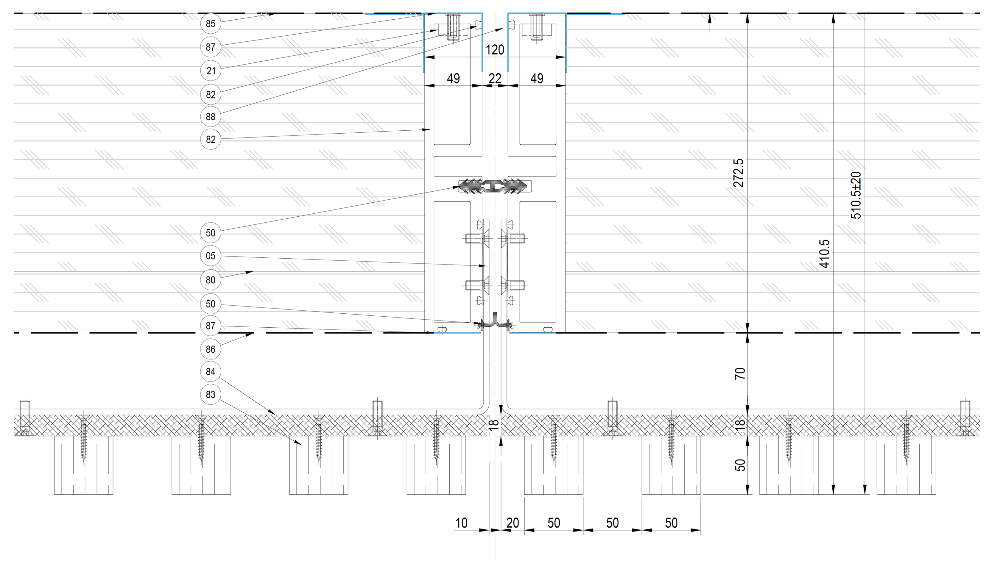
| Figure Code | Layer | Objectives | Characteristics |
|---|---|---|---|
| 05 | Stainless steel sheet AISI 316 | To connect the external cladding to the frame | Structural part |
| 21 | Stainless steel accessory | To connect the anchor to the profile | Structural part |
| 32 | Galvanized steel bracket | - | - |
| 50 | EPDM gasket | Second water barrier | - |
| 50 | EPDM gasket | First water barrier | - |
| 80 | Insulated panel—fiber wood | Insulation | 0.036 W/m2K transmittance |
| 82 | Bio-composite profile- Mullions | To bead the unit load and connect it with the structural slab | To bead the unit load and connect it with the structural slab |
| 83 | Wooden Lamellas | External finishing | Reaction to fire class B1, s0-d0 |
| 84 | Plywood | Internal plywood for false wall | Reaction to fire class B1, s0-d0 |
| 85 | Internal membrane | Vapor barrier | Reaction to fire class A2, s1-d0 |
| 86 | External membrane | Water barrier, wind load resistance | Reaction to fire class A2, s1-d0 |
| 87 | Tape bioadhesive | To stick the membrane to the frame | - |
| 88 | Foam rubber | To not vibrate the internal key | - |
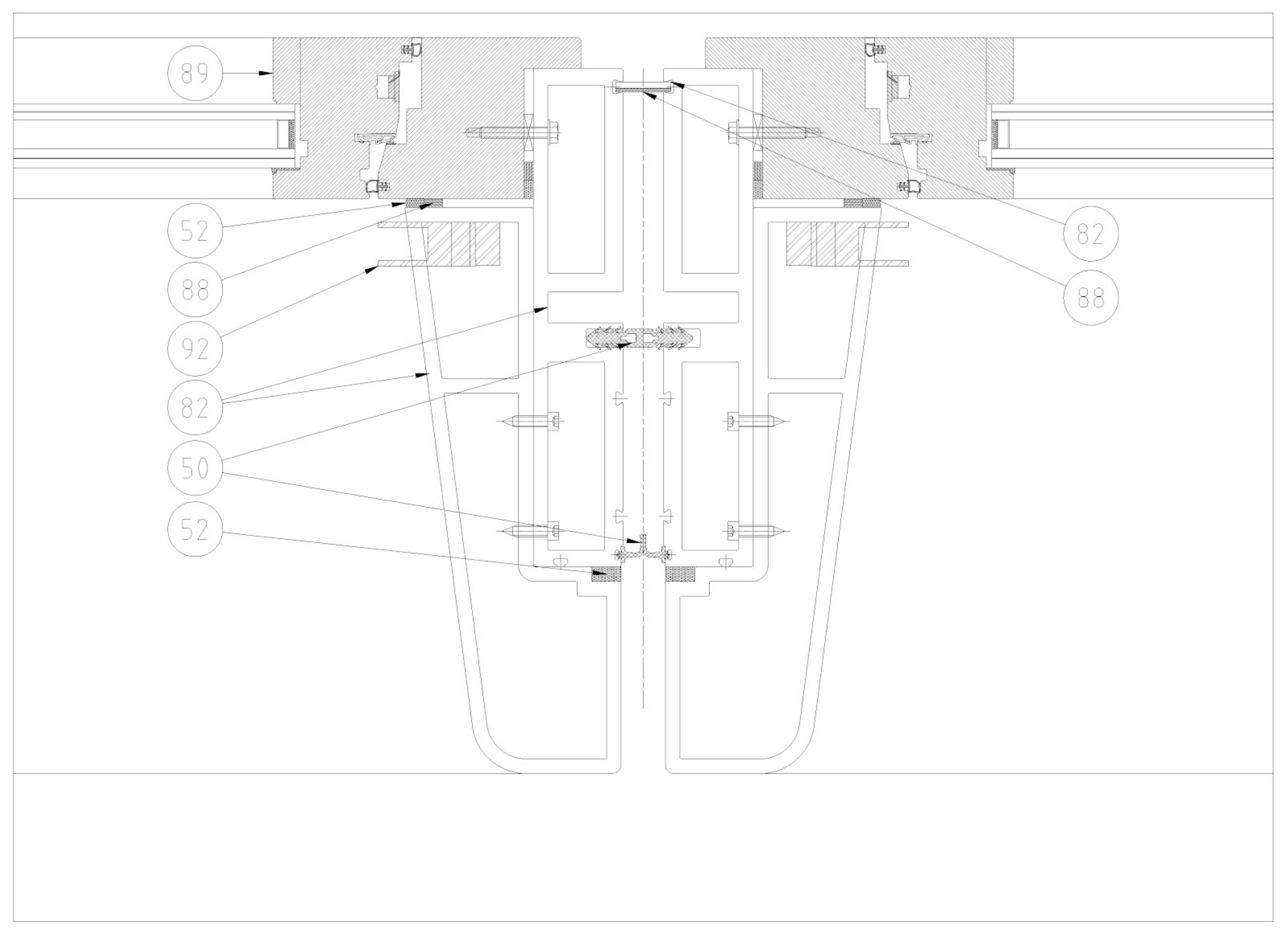
| Code | Layer | Objectives | Characteristics |
|---|---|---|---|
| 9 | Openable | Natural ventilation | - |
| 50 | EPDM gasket | Second water barrier | - |
| 50 | EPDM gasket | First water barrier | - |
| 52 | Water seal silicone black color | To join the external frame to the internal frame | - |
| 52 | Water seal silicone black color | To join the openable to the frame | - |
| 82 | Bio-composite profile–internal key | To join two units | Thickness 3.5 mm |
| 82 | Bio-composite profile–mullions | To bead the unit load and connect it with the structural slab | Thickness 8/10 mm |
| 82 | Bio-composite profile–external frame | To cover the bio-composite profile—aesthetical aim | - |
| 88 | Foam rubber | To not vibrate the internal key | - |
| 88 | Foam rubber | To not drop the silicone | - |
| 92 | Roller shutter | to guarantee shading elements | - |
Disclaimer/Publisher’s Note: The statements, opinions and data contained in all publications are solely those of the individual author(s) and contributor(s) and not of MDPI and/or the editor(s). MDPI and/or the editor(s) disclaim responsibility for any injury to people or property resulting from any ideas, methods, instructions or products referred to in the content. |
© 2024 by the authors. Licensee MDPI, Basel, Switzerland. This article is an open access article distributed under the terms and conditions of the Creative Commons Attribution (CC BY) license (https://creativecommons.org/licenses/by/4.0/).
Share and Cite
Pracucci, A.; Vandi, L.; Morganti, L.; Fernández, A.G.; Nunez Diaz, M.; Navarro Muedra, A.; Győri, V.; Kouyoumji, J.-L.; Astudillo Larraz, J. Design and Simulation for Technological Integration of Bio-Based Components in Façade System Modules. Buildings 2024, 14, 1114. https://doi.org/10.3390/buildings14041114
Pracucci A, Vandi L, Morganti L, Fernández AG, Nunez Diaz M, Navarro Muedra A, Győri V, Kouyoumji J-L, Astudillo Larraz J. Design and Simulation for Technological Integration of Bio-Based Components in Façade System Modules. Buildings. 2024; 14(4):1114. https://doi.org/10.3390/buildings14041114
Chicago/Turabian StylePracucci, Alessandro, Laura Vandi, Luca Morganti, Ana Gallego Fernández, Miguel Nunez Diaz, Arsenio Navarro Muedra, Viktor Győri, Jean-Luc Kouyoumji, and Julen Astudillo Larraz. 2024. "Design and Simulation for Technological Integration of Bio-Based Components in Façade System Modules" Buildings 14, no. 4: 1114. https://doi.org/10.3390/buildings14041114