Article

Study on the Mechanical Properties and Design Method of Frame-Unit Bamboo Culm Members Based on Semi-Rigid Joints

1
Center for Balance Architecture, Zhejiang University, Hangzhou 310028, China
2
Department of Civil Engineering, Zhejiang University, Hangzhou 310058, China
3
Architectural Design & Research Institute of Zhejiang University Co., Ltd., Hangzhou 310028, China
*
Author to whom correspondence should be addressed.
Buildings 2024, 14(4), 991; https://doi.org/10.3390/buildings14040991
Submission received: 5 March 2024 / Revised: 27 March 2024 / Accepted: 29 March 2024 / Published: 3 April 2024

Abstract

:
The frame-unit bamboo culm structure system offers a novel approach to bamboo structure, combining advantages like reduced construction times and simplified joint designs. Despite its benefits, there is limited research on its mechanical properties and computational methodologies. This study conducted bending performance tests on simply supported frame-unit bamboo culm structures, revealing that the bending stiffness of the structure increases with the number of bolts in the edge joints, though with diminishing efficiency. Based on the experimental observations, a calculation model for this type of structure was established, proposing formulas to describe the stiffness relationships between the corner joints, edge joint, and the overall structure. Numerical simulations calculated the stiffness of the edge joint as a function of the number and placement of bolts, indicating that positioning bolts closer to the outer side enhances edge joint stiffness. By inputting the various rotational stiffness values of corner joints into the simulations and stiffness formulas, consistent total stiffness values were obtained, validating the proposed stiffness relationship formulas. The average stiffness values of the corner joints were derived from these formulas and experimental data, and the rotational stiffness of other types of corner points can also be obtained using this method. Furthermore, a finite element computational method tailored for this structural system was introduced, converting the actual structure into a beam element model for calculation. The equivalent joint forces can be distributed to various components of the actual structure, resulting in the internal force distribution of bamboo culms and bolts in the actual structure, thus achieving the design of the components. The calculated displacement values obtained from this method are close to the displacement values in the experiment, proving the feasibility of this method.

1. Introduction

The production process of building materials such as steel bars and cement generates a large amount of carbon and harmful gas emissions [1], exacerbating global climate issues such as climate change and environmental pollution. Promoting natural building materials can help alleviate these problems. Bamboo and wood are two common natural building materials that have been widely used in construction projects, where bamboo has higher carbon sequestration efficiency [1] and better mechanical properties than wood [2,3]. A series of studies and engineering examples have proved the feasibility of bamboo as a building material [4,5]. Compared with engineered bamboo, raw bamboo culms do not require the use of adhesives and are more environmentally friendly as a building material.
The different cross-sectional geometries of natural bamboo culms, the anisotropy of bamboo materials, the different mechanical properties of different types of bamboo [6,7], the different mechanical properties of different parts of the same bamboo culm [8], and the different orientations of different joints connecting different bamboo tubes in the bamboo tube structure constrain the standardization of the design of the bamboo tube structures and bring difficulties to the promotion of the bamboo tube structure. Amede et al. [9] found that current standards for bamboo structures are inadequate for its full use as a structural material, indicating a need for a universally applicable design and construction specification to overcome design and construction challenges of bamboo structures. Ma et al. [10] proposed a method for grading based on the minimum outer diameter of bamboo. They measured and analyzed the geometric, physical, and mechanical properties of multiple bamboo culms, and graded the bamboo culms with different processing techniques based on the measurement data. This study contributes to the standardization design of bamboo tube structures.
Joint design is an important part of bamboo tube structure design. Hong et al. [11] divided the common bamboo tube connection joints into two categories of traditional joints and modern joints, where the traditional joints include tied connections and mortise and tenon connections, and the modern joints include types such as bolts, steel components, and fillers. In the German–Chinese House at the Shanghai World Expo 2010 [12], the joints are made of prefabricated steel parts with grouting, and the prefabricated steel components are capable of connecting bamboo tubes in different directions. Huang et al. [13] proposed a bamboo tube joint using grouting and built-in steel sheet connection, and the tests showed that this type of joint has high load-bearing capacity. These improved grouted joints showed better mechanical properties, but the grouting significantly increased the self-weight of the structure and could not take advantage of the light weight of the bamboo tube structure. Richard et al. [14] proposed a new type of joint, connecting bamboo tubes with steel rings and pieces, and the stiffness and strength of this type of joint were proved to be more than that of the traditional grouted bamboo tube joint through tests. Benoit et al. [15] proposed a bamboo tube joint using a combination of wood plugs and metal clamps, and demonstrated through experiments and numerical simulations that the joint could be used for the longitudinal extension of bamboo tubes with good strength, providing a new idea for lightweight joints of bamboo tube structures.
Bolt connection is one of the most practical metal connectors, which has the advantages of simple construction and low cost. It is widely used for connecting round bamboo joints and specimens. Bolts can be used to assemble scattered bamboo tubes into a bamboo tube bundle column with a strong axial compression ability. For instance, in the studies by Nie [16] and Yang [17], long bolts were used to laterally connect multiple parallel bamboo tubes into a bamboo tube column specimen, which demonstrated a strong axial compression performance in tests. Bolts can also be used as embedded parts to form bolted-mortar infill connections (BMIs). Correal et al. [18] proposed a new model to calculate this type of joint, and this model has been validated through experimentation. This research has contributed to the improvement of design procedures and national regulations for BMI connections in Guadua Angustifolia Kunth and other bamboo species.
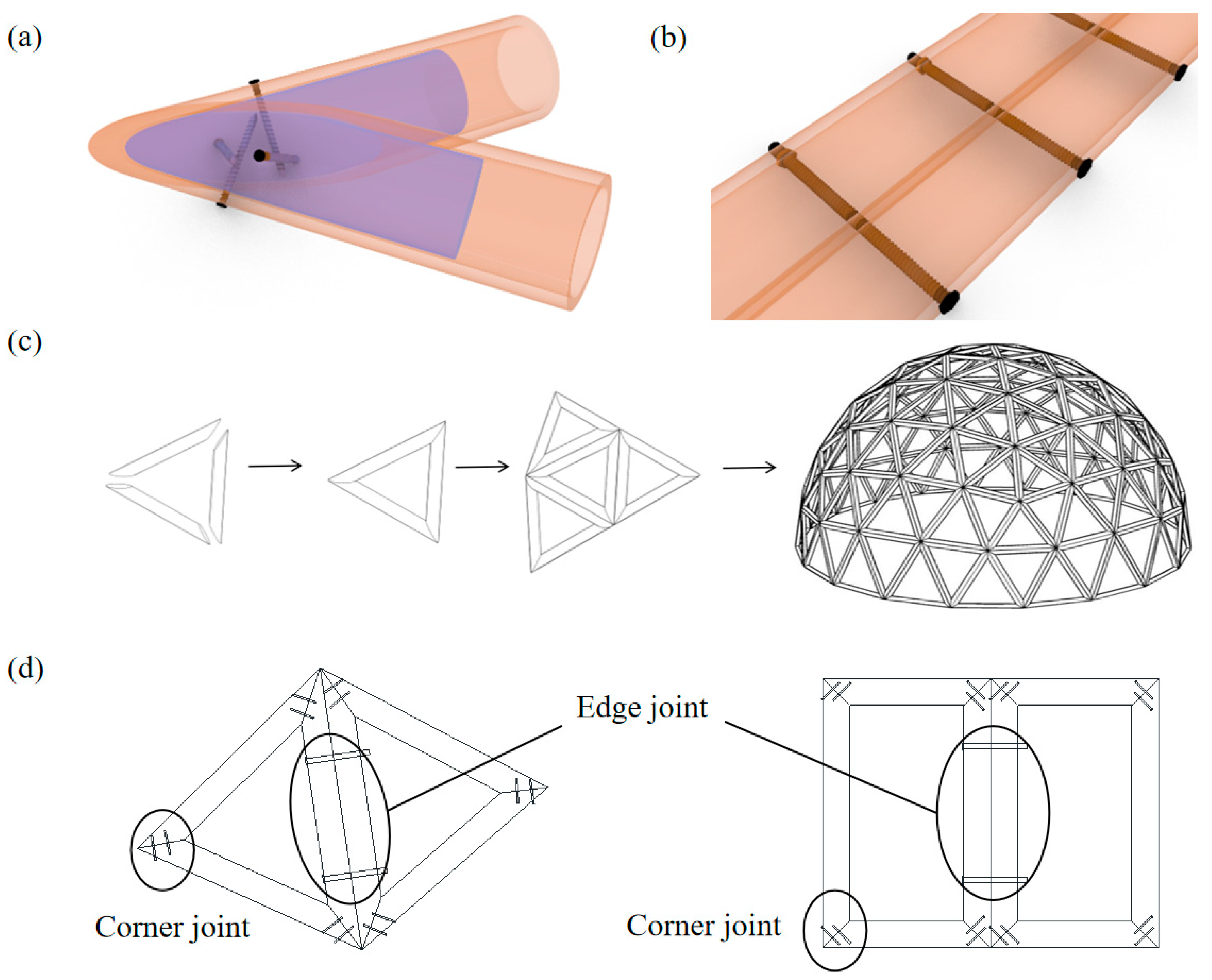
In this paper, a lightweight joint for the cross-connection of bamboo tubes is proposed, as shown in Figure 1a, where wood plugs are embedded in each of the two sides of the bamboo tubes, and each screw is screwed from the outside of one side of the bamboo tube into the wood plug inside the other side of the bamboo tube, and the bamboo tube and the wood plugs are cut at the same angle in the joint part. The joint has the advantages of being of light weight, easy production, and low cost.
The existing bamboo tube space structures can be divided into two types: [19,20] bamboo tube arch structure and bamboo tube lattice structure. Bending and connecting one or more long bamboo tubes forms a large-span bamboo tube arch structure, the disadvantage being that the bending process uses manual labor which makes it difficult to control processing accuracy. The bamboo tube lattice structure uses straight bamboo tubes, which are easy to process and low in cost, but the processing difficulty of multi-directional joints and the customization cost is high. Zhuo et al. [21,22] proposed a framed bamboo culm grid structure system (a frame-unit prefabricated bamboo culm structure), the formation principle of which is shown in Figure 1c,d. Straight bamboo culms are assembled into bamboo culm frame units, which can be in polygonal geometries such as triangles, rectangles, trapezoids, hexagons, and other polygonal geometries; the joints of neighboring culms are called corner joints, which can be connected by a combination of grouting, screws, and wood plugs (Figure 1a), and the joints between neighboring bamboo culm frames are called edge joints, which use bolts as connectors (Figure 1b).
After all the bamboo culm frame units are connected, the overall structure can be formed. This paper employs experimental, numerical simulation and theoretical analysis to investigate the flexural performance of frame-unit bamboo culm joints. The focus is on studying the semi-rigid bearing mechanism and calculation method for joints when materials are in the elastic phase at edge and corner joints. The research process of this paper is illustrated in Figure 2.

2. Bamboo Culm Frame Specimen Bending Performance Test

2.1. Overview of the Test

Moso bamboo is one of the most widely distributed bamboo species in China, mainly found in the southern regions of China. It is extensively used in bamboo architectural structures [23].
The bamboo used for the experiment is Moso bamboo grown in the southern mountainous areas of China. It has a growth age of about 4 years, with internode spacing between 20–40 cm and a wall thickness between 7.5–8.5 mm. The outer diameter of the bamboo culm was measured using a vernier caliper and ranged from 75 mm to 95 mm.
The specimen in this study is composed of two adjacent rectangular bamboo culm frames (Figure 3a). Each bamboo culm frame is handmade, and wooden plugs are inserted into the ends of the bamboo culms. Screws with a diameter of 4 mm are driven into the exterior wall of one side of the bamboo culm, penetrating through to the wooden plug located within the bamboo culm on the opposite side; a single corner joint is formed using four screws (Figure 3b). The experiment was conducted in an environment with a temperature of 25 °C and an air humidity of about 45%. Place two bamboo culm frames side by side. After drilling, use long bolts to connect the adjacent bamboo culms placed in parallel to form a test specimen. (The diameter of the holes in the bamboo culms and the diameter of the long bolts are the same, at 10 mm. The long bolts are made of Q235 steel, with a length of approximately 200 mm.)
The specimens were rested in a simply supported manner on the bull legs of the steel frame test rig (shown in Figure 4).
The positions of bolt holes are marked as A, B, C, B’, and A’, respectively. The dimensions of the assembled specimens are shown in Figure 5. The loading position is in the middle of the specimen (Figure 4). Loading is performed by stacking sandbags, with each sandbag weighing 10 kg (±0.5 kg). When the sixth sandbag was placed, the structure experienced significant displacement and could no longer continue to accommodate more sandbags. For safety reasons, the load at this point is considered the maximum load. Loading tests were conducted on specimens with 2, 3, and 5 bolts connected to the edge joints; the experimental parameters for each model are shown in Table 1. The specimen number “Sn” indicates that the number of bolts in the edge joint is n.

2.2. Experimental Process and Result Analysis

The two bamboo culm frames of the specimen are in the same plane when unloaded. Vertical displacement occurs at the edge joint positions of the specimen, gradually increasing with the number of sandbags (Figure 6a), and there is a gap between the two bamboo culms at the corner joint (Figure 6b). The measuring point for vertical displacement is at the midpoint of the lower edge of the edge joint bamboo culm (Figure 4), measured using a laser distance detector with an accuracy of 0.1 mm. During loading, sandbags are placed one by one, and data from the displacement detector are read only after the vertical displacement stabilizes after placing a sandbag (and the unloading stage is similar). The deflection of the measuring point under each stage of loading is:
u i = w i w 0
where w i is the reading at stage i, and w 0 is the reading without load. The data recorded at each loading step are used to create the load–displacement relationship shown in Figure 7.
Before loading, due to the presence of bamboo nodes, it is impossible to achieve a complete fit between the outer walls of adjacent bamboo culms. In addition, it is also impossible to achieve a complete fit between the bamboo culm bolt hole wall and the bolt thread, so the deformation during the loading process includes measurement errors caused by these factors. In contrast, the unloading process has achieved close contact between different materials, and the corresponding load–displacement relationship can better reflect the true mechanical properties of the specimens.
The total bending linear stiffness K l (hereafter referred to as total linear stiffness) of the bamboo culm frame in the elastic phase is defined as the ratio of the out-of-plane load at the edge joints to the vertical displacement occurring in the direction of action:
K l = F d
where ΔF and Δd are the incremental load and the displacement of the measuring point.
The test data from the unloading stage were selected for linear fitting (using the polyfit function in MATLAB.R2020b) to obtain the fitted values of total linear stiffness K l , f i t (Figure 7). This shows that the total bending linear stiffness is positively correlated with the number of bolts. However, as the number of bolts increases, the efficiency of stiffness increases decreases gradually.

2.3. Synergistic Relationship between Corner Joints and Edge Joints

During the loading process, no visible bending occurred in each bamboo culm, while vertical displacement occurred at the edge joints. At the same time, the gap at the corner joints gradually widened with the increase of the load (Figure 6b), indicating that the corner joints and edge joints are not completely rigid (semi-rigid). Define k s a and k c a as the rotational stiffness of the edge joints and corner joints, respectively:
k s a = def Δ M s Δ θ s
k c a = def Δ M c Δ θ c
where M s , θ s are the bending moments and turning angles of the edge joints, M c ,   θ c are the bending moments and turning angles of the corner joints, and the units of bending moments and turning angles are N · m m , R a d , respectively.
To convert the relationship between force and displacement into the relationship between bending moment and rotation, the various bamboo culms are simplified into rigid members, and a simplified diagram for the internal force calculation of the frame-unit bamboo culm members shown in Figure 8 is established.
In Figure 8, F is the vertical force acting on the upper surface of the edge joint bamboo culms, b is the distance between the axis of the edge joint bamboo culm and the support bamboo culm (hereinafter referred to as the shear span). Under the action of F, both the edge joint and the corner joints produce vertical displacement.
When the corner joints are completely rigid, define the edge joint linear stiffness as follows:
k s l = def Δ F Δ w
When the edge joint is completely rigid, define the corner joint linear stiffness as follows:
k c l = def Δ F Δ w
According to Figure 8:
M s = 0.5 F b θ s = 2 θ
M c = 0.25 F b θ c = θ
When the structural deformation is small:
θ ~ tan θ = w b
The numerator and denominator in Equation (3) are represented by ΔF and Δw, respectively, and the relationship between the edge joint linear stiffness and its rotational stiffness can be obtained:
k s a = 0.5 F b 2 θ = 0.5 F b 2 w b = b 2 4 k s l
Similarly, the relationship between the corner joint linear stiffness and its rotational stiffness can be obtained from Equation (4).
k c a = b 2 4 k c l
The unit of edge and corner joint linear stiffness is N/mm. From Equations (5) and (6), the linear stiffness is not a property of the joint itself, and its value is related to structural parameters such as rotational stiffness and span.
In structural mechanics, the shear distribution method is solved by analyzing the series–parallel relationship and stiffness relationship of the members [24]. In the structure shown in Figure 8, the two corner joints in a bamboo culm single-sided frame structure are in a parallel relationship, and the relationship between the corner joints and the edge joint constitutes a series relationship; the series and parallel relationships of the assembled joints are shown in Figure 9.
According to Figure 9, establish the relationship between the overall rotational stiffness and that of the edge and corner joints.
1 K a = 1 2 k c a + 1 k s a + 1 2 k c a = 1 k c a + 1 k s a
Similarly, the relationship between total linear stiffness and the linear stiffness of the edge and corner joints can be established.
1 K l = 1 k c l + 1 k s l

3. Numerical Simulation

3.1. Overview

3.1.1. Setting of Numerical Simulation

  • The finite element software Abaqus2021 is used for modelling and the calculation of numerical simulation. Since the two neighboring bamboo culm frames have symmetry, in order to improve the computational efficiency, only a single bamboo culm frame is established, and symmetrical constraints are applied to the mid-span cross-sections of truncated bolts;
  • The influence of bamboo nodes is not taken into account;
  • The actual bamboo culm wall has a different elastic modulus along the axial, lateral, and radial directions, which is simplified by setting up bamboo culms as orthotropy material in both axial and lateral directions and ignoring the difference in the mechanical parameters of the bamboo culms along the radial direction;
  • The diameter of the opening of the bamboo culm is the same as the diameter of the bolt, which is taken as 10 mm, ignoring the effect of the thread on the bamboo culm;
  • The loading plate for applying load is set to simulate the sandbag load in the test.

3.1.2. Material Properties

According to the test data of García et al. [25], the mechanical properties of bamboo are shown in Table 2, where direction two is the bamboo culm axis (fiber) direction, and directions one and three are perpendicular to the axis direction (the bamboo culm material property setting direction is the local coordinate system of the bamboo culm). Emn, vmn, and Gmn are the elastic modulus, Poisson’s ratio, and shear modulus. The yield strength of the bolt is 235 MPa, the elastic modulus is 206 GPa, and the Poisson’s ratio v is 0.3. According to the axial compression test conducted by Zhang et al. [26,27], the axial compressive yield strength is 50.3 Mpa, and the shear yield strength is 25 Mpa. The compressive strength σc of the bamboo culm groove is calculated according to the formula proposed by Peng Hui et al. [28]:
F s = 0.8 σ 1 d t
where Fs is the yield load of the bearing compression of the bolt hole, σ1 is the compressive strength of bamboo culm with grain, d is the diameter of the hole, and t is the thickness of the bamboo culm. Rewriting Equation (14) can obtain the compressive strength of bamboo culm at the location of the bolt hole wall:
σ c = F s d t = 0.8 σ 1 = 40.2   M P a

3.1.3. Calculation Model

The friction coefficient between the bolt and the bamboo culm wall is set to 0.3. The loading plate is used solely for loading and is not a component of the structure, so the coefficient of friction between it and the bamboo culm surface is 0. Only compressive forces are transmitted in the normal direction between the loading plate, bolt, and bamboo culm. The locations of the bolts in each model are the same as those in the experimental specimens (Table 1). The components established include bamboo culms and bolts, and the outer diameter and wall thickness of the bamboo culms are 80 mm and 8 mm, respectively. The dimensions of the bamboo culm frames are shown in Figure 5, and the diameter of the bolts is 10 mm. The displacement in the y-direction and z-direction of the lower edge of the support bamboo culm, and the x-direction displacement at various points on the cross-section of each bolt is restrained, forming a semi-span simple supported structure. The mesh consisted of the eight-node hexahedral elements. The loading position on the edge joint bamboo culm does not include the angled region at the ends of the bamboo culm. A linearly increasing concentrated force is applied at the center position of the loading plate (the load remains consistent with the experiment direction: -y, maximum value: 620.3 N).
The assembled structure is shown in Figure 10.

3.2. Semi-Rigid Corner Joint

The spatial relationship between the various materials at corner joint positions is complex, making it difficult to accurately model according to the actual situation. To obtain the average rotational stiffness value of the corner joints of the test specimens, the calculations are first performed assuming the corner joints are completely rigid, to obtain the stiffness values at the edge joint. Then, the corner joints are considered semi-rigid to determine the overall stiffness of the structure. The obtained values are compared with the calculated values obtained from the stiffness relationship formula to validate the accuracy of the formula. Finally, based on the experimental data and the stiffness relationship formula, the average rotational stiffness value of the corner joints of the test specimens is determined.

3.2.1. Set the Corner Joints as Rigid

The points at the ends of both bamboo culms are set as coupling constraints, with the highest point of the side bamboo culm serving as the control point. This ensures that there is no relative displacement between the points at the ends of the bamboo culms, thereby forming a rigid connection (Figure 11).
In the Visualization module, view the step time and corresponding load when the bolt yields (yield load). The three models with two, three, and five bolts, respectively, have yield load values of 245 N, 330 N, and 460 N. When the bolt yields, the Mises stress distribution and the shape of the bending moment for the bolt are shown in Figure 12; the shape of the bending moment diagram is the same for each bolt, but the values differ. The distribution ratios of bolt moments for each model are presented in Table 3.
The displacement measurement point is located at the midpoint of the lower edge of the edge joint bamboo culm, consistent with the experimental setup. The total linear stiffness value K l , s i m , shown in Table 4, is calculated using Equation (16). Here, w50 and w100 represent the vertical displacements at the measurement point under loads of 50 N and 100 N, respectively. Comparing K l , s i m with K l , f i t (Figure 7) reveals that the total stiffness values calculated, assuming fully rigid corner joints, significantly deviate from the experimental results, underscoring the importance of accounting for the semi-rigidity characteristics of the corner joints.
K l , s i m = 2 Δ P Δ w = 100 w 100 w 50
According to Equation (13), the total linear stiffness is the edge joint linear stiffness when the corner joint stiffness is infinite:
lim k cl 1 K l = 1 k s l

3.2.2. Set the Corner Joints as Semi-Rigid

The steps to modify the corner joints to be semi-rigid are as follows (Figure 13):
  • Delete the rigidity constraint from the corner joints.
  • Set coupling constraints between various points at the end of each bamboo culm and its respective highest point (control point). Wire feature was established between control points of adjacent bamboo culms.
  • Create a hinge-type connector and assign different rotational stiffness values.
  • This connector was applied to the wire features, forming a semi-rigid joint.
  • Move the bamboo culm to the starting position.
By incorporating the rotational stiffness values of different corner joints into numerical simulations, combined with Equation (16), the total stiffness value of the structure can be obtained (simulated values K l , s i m ).
These varying rotational stiffness values of corner joints were then converted into linear stiffness values, which were substituted into Equation (13) (the stiffness values of the edge joints are K l , s i m , shown in Table 4) to derive a series of total linear stiffness values (theoretical values K l , e q u ).
By comparing the values of K l , s i m and K l , e q u , it was found that the total linear stiffness values calculated by the two methods are close (Table 5), proving the accuracy of the proposed stiffness relationship formula.
The values of linear stiffness k c l for the considered semi-rigid corner joints can be obtained by bringing the first and second rows of Table 4 into Equation (13) as k s l and K l , respectively. The value of k c l , after substituting into Equation (11), is transformed into the value of k c a , as shown in Table 6. This value is the average rotational stiffness of the four corner joints connecting the edge joints in Figure 7, not the rotational stiffness of the corner joints in a specific certain position.

3.3. Semi-Rigid Edge Joint

To analyze the effect of positions on the stiffness of the edge joint when the number of bolts remains the same, s is defined as the distance from the outermost bolt to the axis of the side bamboo culm (defined as “side distance”, Figure 14), and k s l s is the linear stiffness of the edge joint as a function of s, the bolts arranged at equal distances. Through the numerical simulation method established in this paper, the k s l corresponding to different values of s can be obtained, as shown in Table 7. The linear regression equations of k s l and s are established as follows:
k s l s = A s + B
where A and B are coefficients to be determined.
Matlab.R2020b was used to linearly fit the ( s , k s l ) points of Table 7, according to Equation (18); the k s l s relationship can be obtained for different numbers of bolts (Figure 15). The stiffness values calculated from the fitted relationship equation have an error of less than 3% compared to the stiffness values obtained from the numerical simulation, which indicates that the regression effect is good. It was also found that, under the condition of the same number of bolts, k s l increases linearly with the decrease of s, which indicates that the outer bolt closer to the corner joint is more beneficial for stiffness improvement.
By substituting the fitting equation in Figure 15 and b = 420 mm into Equation (10), the calculation formula for the rotational stiffness of the edge joint can be obtained when the diameter of the bolts in the edge joint is set to 10 mm.
k s a ( s ) = 3797.5 s + 260.2 × 10 4 ,                             n = 2 5071.5 s + 334.3 × 10 4 ,                             n = 3 6933.5 s + 430.7 × 10 4 ,                             n = 5  
From Equations (3) and (4), the rotational stiffness of the joint is the relative angle of rotation produced under the action of unit bending moment, which is a property of the joint itself. Therefore, Equation (19) is a general formula for the rotational stiffness of the corner joint when the diameters of the bolts of the edge joint are 10 mm. Similarly, the rotational stiffness values k c a , in Table 6, are generic values for corner joints in a specific configuration (using four screws combined with wooden plugs). These values and formulas derived from experimental data, numerical simulations, and theoretical derivations provide a basis for the setting of joint semi-stiffness in structural finite element analyses.

4. Finite Element Analysis of Structures and Design Methods for Components

The finite element analysis method of the structure models the components according to the axes and, since the calculation formulas and parameters obtained in Section 3 of this paper are based on solid modelling, a practical method for the finite element analysis and component design of the bamboo culm and frame-unit bamboo culm structure will be presented in this chapter. The equivalent joint forces and joint deformations in the structure are first analyzed according to the computational model in Figure 8, and then the internal forces of the bamboo culm and bolts are calculated in combination with the computational model. Then the allowable stresses and deformations of each component are verified.
Taking the model shown in Figure 5 as an example, the material, size, and number of bolts of the two bamboo culm frame units are the same as those of the S5test in the test, i.e., the outer diameter D of the bamboo culm is 80 mm, the thickness of the bamboo wall t is 8 mm, and the size of the outer frame of the bamboo culm frame: L × H = 800 mm × 500 mm (axial figure: a = 720 mm, b = 420 mm). The edge joint is connected by five bolts with d = 10 mm, the side distance s is 90 mm, and the rest of the bolts are arranged at an equal distance from each other. The corner joints are connected by four screws and wooden plugs. The support bamboo culm is used as the simply supported side. The top of the edge joint bamboo culm is subjected to a uniform load, and the total force F is consistent with the experimental value in Figure 7, which is taken as 413 N.

4.1. Structural Finite Element Analysis Methods

4.1.1. Structural Modelling

The equivalent computational model of each member is shown in Figure 16:
  • Select the axis of each bamboo culm as the position of the equivalent members;
  • An equivalent bolt is set at the midpoint of the edge joint bamboo culm, and the connection between the equivalent bolt and the edge joint bamboo culm is a rigid connection. The middle position of the equivalent bolt is disconnected, and the disconnection is set as a semi-rigid connection;
  • All corner joints are set to semi-rigid connections;
  • The two ends of the support bamboo culms are set as hinged.

4.1.2. Parameter Settings

Since the corner and edge joint stiffnesses studied in this paper already include the deformation of the material itself, to avoid repeated calculations, the members should be set as rigid bodies during the finite element analysis of the structure, i.e., the stiffness and elastic modulus of various materials are set to infinity. The semi-rigid joints are set as follows.
From Table 6, the rotational stiffness of the corner joints is:
k c a = 250.1 × 10 4   N · m m / R a d
From Equation (19), the edge joint rotational stiffness is:
k s a = 6933.5 × 90 + 430.7 × 10 4 = 368.3 × 10 4   N · m m / R a d
Taking the test data at n = 5 in Figure 7 when the load is 413 N, the uniform load on the edge joint bamboo culms is:
q = F 2 L 2 D = 413 2 × 800 2 × 80 = 0.32   N / m m

4.1.3. Calculation Result

The maximum deflection obtained by using Abaqus2021 is 12.2 mm, while the measured value of the test in Figure 7 is 13.0 mm, which indicates that the calculation method in this paper has a good calculation accuracy.

4.2. Design Methods for Components

4.2.1. Internal Force Distribution

The software calculates the maximum bending moment on the equivalent edge joint bolt to be 8.68 × 10 4   N · m m , which is the value of the combined cross-sectional internal force in the mid-span of each bolt in the actual structure. So, this equivalent joint force needs to be assigned to each bolt.
The bending moment at the equivalent edge joint was distributed to each bolt according to the distribution ratio coefficients in Table 3, and the values of bending moments on the five bolts were obtained as 2.24, 1.47, 1.27, 1.47, and 2.24 ( 10 4   N · m m ) , respectively. Substituting these values into the torque calculation sketch in Figure 17a gives the torque on each section of the bamboo culm at the edge joints (Figure 17b).

4.2.2. Strength Calculation of Components

Figure 18 shows the force sketch of the bolt in bending. Due to the thin wall of the bamboo culm, the constraint of the bamboo culm wall on the bolt can be considered as simple support, and the force between the outermost bolt and the walls of the bamboo culm are as follows:
0.5 P = M D = 2.24 × 10 4 80 = 280   N
Calculate the bearing compression stress at the location of the bamboo culm hole wall:
σ x c = 0.5 P d t = 280 10   ×   8 = 3.5   MPa < 40.2   MPa
Calculate the bending strength of the outermost bolt:
σ m a x = M W = 2.24   ×   10 4 π   ×   10 3 32 = 228.2   M P a < 235   M P a
Calculate the torsional strength of the bamboo culm by taking the maximum torque of the bamboo culm:
τ m a x = T W p = 4.34   ×   10 4 π 16   ×   80 80 4 72 4 = 1.3   M P a < 25   M P a

5. Conclusions

This study combined experimental and numerical simulation methods to conduct a comprehensive analysis of the two main types of joints in this structural system, and has successfully established corresponding calculation models. Furthermore, a new finite element calculation method for this structure has been proposed.
Experiments on specimens with bolt diameters of 10 mm and bolt counts of two, three, and five have been conducted, recording the vertical deformation and load relationship curves. Linear fitting of the unloading phase data was performed to obtain the total stiffness. The results indicate that an increase in the number of bolts leads to an increase in total stiffness, but with diminishing efficiency. Observations from the experiments reveal that, despite no visible deformation in the bamboo culms during the loading process, both the corner and edge joints connecting the bamboo culms underwent varying degrees of deformation, indicating that these joints are not completely rigid. Based on these observations, a calculation model for the frame-unit bamboo culm considering the semi-rigidity of the joints has been further proposed. This study has derived formulas for converting linear stiffness to rotational stiffness for both corner and edge joints, as well as a universal stiffness relationship formula between joints.
This study also explores a numerical simulation method for frame-unit bamboo culm structure. By setting the corner joints as fully rigid for numerical simulation, the calculation formulas for edge joints under different bolt configurations were obtained, showing that the placement of outer bolts closer to the corner joints significantly increases the stiffness of the edge joints. By treating corner joints as semi-rigid and incorporating different values of rotational stiffness for corner joints into both numerical simulations and the stiffness relationship formula, the consistency in the total stiffness values obtained from both methods confirms the accuracy of the proposed stiffness relationship formula. By applying the proposed stiffness relationship formula, this study has calculated the average rotational stiffness values for the corner joints of the experimental specimens. This provides a new method for determining the rotational stiffness values of corner joints in various construction forms.
Lastly, based on the calculation model of the frame-unit bamboo culm structure established in this paper, a finite element analysis method for this type of structure based on semi-rigid joints is proposed. This method converts all members into rigid beam elements, and remodels accordingly. Following the principle of equal stiffness, establish equivalent semi-rigid corner and edge joints to connect beam elements. After calculation, the equivalent joint internal force and joint deformation can be obtained. The equivalent joint internal force can be distributed to obtain the distribution of the internal force of the bamboo culms and bolts in the actual structure. The equivalence of the joint deformation values to the experimental values demonstrates the feasibility of this method.

Author Contributions

Conceptualization, G.W. and X.Z.; methodology, G.W. and X.Z.; software, S.Z.; validation, J.W. and S.Z.; experiment, J.W. and S.Z.; formal analysis, G.W.; resources, J.W. and S.Z.; data curation, J.W.; writing—original draft preparation, G.W.; writing—review and editing, G.W. and X.Z.; supervision, X.Z.; project administration, X.Z.; funding acquisition, X.Z. All authors have read and agreed to the published version of the manuscript.

Funding

This research was funded by the National Key Research and Development Program of China, Grant No. 2017YFC0703500.

Data Availability Statement

Data will be made available on request.

Conflicts of Interest

Authors Xin Zhuo, Shenbin Zhang and Jie Wu was employed by the company Architectural Design & Research Institute of Zhejiang University Co., Ltd. The remaining authors declare that the research was conducted in the absence of any commercial or financial relationships that could be construed as a potential conflict of interest.

References

  1. Lorenzo, R.; Mimendi, L. Digitisation of bamboo culms for structural applications. Build. Eng. 2020, 29, 101193. [Google Scholar] [CrossRef]
  2. Escamilla, E.Z.; Habert, G. Environmental impacts of bamboo-based construction materials representing global production diversity. J. Clean. Prod. 2014, 69, 117–127. [Google Scholar] [CrossRef]
  3. Anokye, R.; Bakar, S.E.; Ratnansingam, J.; Awang, B.K. Bamboo properties and suitability as a replacement for wood. Pertanika J. Sch. Res. Rev. 2016, 2, 63–79. [Google Scholar] [CrossRef]
  4. Chung, K.F.; Yu, W.K. Mechanical properties of structural bamboo for bamboo scaffoldings. Eng. Struct. 2002, 24, 429–442. [Google Scholar] [CrossRef]
  5. Adier, M.F.V.; Sevilla, M.E.P.; Valerio, D.N.R.; Ongpeng, J.M.C. Bamboo as Sustainable Building Materials: A Systematic Review of Properties, Treatment Methods, and Standards. Buildings 2023, 13, 2449. [Google Scholar] [CrossRef]
  6. Liu, P.; Zhou, Q.; Fu, F.; Li, W. Effect of bamboo nodes on the mechanical properties of p. Edulis (Phyllostachys edulis) bamboo. Forests 2021, 12, 1309. [Google Scholar] [CrossRef]
  7. Chen, M.; Ye, L.; Li, H.; Wang, G.; Chen, Q.; Fang, C.; Dai, C.; Fei, B. Flexural strength and ductility of moso bamboo. Constr. Build. Mater. 2020, 246, 118418. [Google Scholar] [CrossRef]
  8. Li, R.R.; He, C.J.; Peng, B.; Wang, C.G. Differences in fiber morphology and partial physical properties in different parts of Phyllostachys edulis. J. Zhejiang AF Univ. 2021, 38, 854–860. (In Chinese) [Google Scholar] [CrossRef]
  9. Amede, E.A.; Hailemariama, E.K.; Hailemariam, L.M.; Nuramo, D.A. A Review of Codes and Standards for Bamboo Structural Design. Adv. Mater. Sci. Eng. 2021, 2021, 4788381. [Google Scholar] [CrossRef]
  10. Ma, R.; Chen, Z.; Du, Y.; Jiao, L. Structural Grading and Characteristic Value of the Moso Bamboo Culm Based on Its Minimum External Diameter. Sustainability 2023, 15, 11647. [Google Scholar] [CrossRef]
  11. Hong, C.K.; Li, H.T.; Lorenzo, R.; Wu, G.; Corbi, I.; Corbi, O.; Xiong, Z.H.; Yang, D.; Zhang, H.Z. Review on connections for original bamboo structures. J. Renew. Mater. 2019, 7, 713–730. [Google Scholar] [CrossRef]
  12. Dai, P.Q.; Luo, Z.Y.; He, M.J. Structural design and analysis for shanghai expo special project DuC. Struct. Eng. 2011, 27, 6–11. (In Chinese) [Google Scholar] [CrossRef]
  13. Huang, T.; Zhuo, X. Experimental Study on the Bending Properties of Grouting Butt Joints Reinforced by Steel Plate Embedded in Bamboo Tube. J. Renew. Mater. 2022, 10, 993–1005. [Google Scholar] [CrossRef]
  14. Moran, R.; García, J.J. Bamboo joints with steel clamps capable of transmitting moment. Constr. Build. Mater. 2019, 216, 249–260. [Google Scholar] [CrossRef]
  15. Lefevre, B.; West, R.; O’Reilly, P.; Taylor, D. A new method for joining bamboo culms. Eng. Struct. 2019, 190, 1–8. [Google Scholar] [CrossRef]
  16. Nie, S.D.; Yu, P.; Huang, Y.Z.; Luo, Y.; Wang, J.L.; Liu, M.; Elchalakani, M. Experimental study on compressive performance of the multiple-culm bamboo columns connected by bolts. Eng. Struct. 2024, 303, 117525. [Google Scholar] [CrossRef]
  17. Yang, C.C.; Zhuo, X. Research on the Axial Compressive Experiment of Single Tube and Four-tube Bundle of Moso Bamboo. Chin. Overseas Archit. 2020, 10, 200–203. (In Chinese) [Google Scholar] [CrossRef]
  18. Correal, J.F.; Prada, E.; Suárez, A.; Moreno, D. Bearing capacity of bolted-mortar infill connections in bamboo and yield model formulation. Constr. Build. Mater. 2021, 305, 124597. [Google Scholar] [CrossRef]
  19. Minke, G. Building with Bamboo; Birkhäuser: Basel, Switzerland, 2012; pp. 47–66. [Google Scholar]
  20. Liu, K.W.; Xu, Q.F.; Wang, G.; Chen, F.M.; Leng, Y.B.; Yang, J.; Harries, K.A. Contemporary Bamboo Architecture in China; TsingHua University Press: Beijing, China, 2022; pp. 31–55. [Google Scholar]
  21. Zhuo, X.; Dong, S.L. Bamboo tube bundle spatial lattice structure system and construction technology. Spat. Struct. 2021, 27, 3–8. (In Chinese) [Google Scholar] [CrossRef]
  22. Zhuo, X.; Dong, S.L. Frame-unit prefabricated bamboo culm lattice structure system and engineering practices. J. Build. Struct. 2024, 45, 43–51. (In Chinese) [Google Scholar] [CrossRef]
  23. Yu, L.; Wei, J.; Li, D.; Zhong, Y.; Zhang, Z. Explaining Landscape Levels and Drivers of Chinese Moso Bamboo Forests Based on the Plus Model. Forests 2023, 14, 397. [Google Scholar] [CrossRef]
  24. Zhu, C.M.; Zhang, W.P. Structural Mechanics; Higher Education Press: Beijing, China, 2016; Volume 2, pp. 51–54. (In Chinese) [Google Scholar]
  25. García, J.; Rangel, C.; Ghavami, K. Experiments with rings to determine the anisotropic elastic constants of bamboo. Constr. Build. Mater. 2010, 31, 52–57. [Google Scholar] [CrossRef]
  26. Zhang, X.X.; Yu, Z.X.; Yu, Y.; Wang, H.K.; Li, J.H. Axial compressive behavior of Moso Bamboo and its components with respect to fiber-reinforced composite structure. J. For. Res. 2019, 30, 2371–2377. [Google Scholar] [CrossRef]
  27. Walter Liese; Michael Köhl. Bamboo the Plant and Its Use; Springer International Publishing: Cham, Switzerland, 2015; pp. 251–253. [Google Scholar]
  28. Peng, H.; Zhuo, X. Research on Mechanical Behavior of the Screwed Connection at the End of Bamboo Strip; Zhejiang University: Hangzhou, China, 2022; (In Chinese). [Google Scholar] [CrossRef]
Figure 1. Structural forming principles and two types of joints. (a) corner joint. (b) edge joint. (c) formation of the structure. (d) the positions of the corner joint and edge joint.
Buildings 14 00991 g001
Figure 2. Research process.
Buildings 14 00991 g002
Figure 3. Corner joint and edge joint. (a) edge joint. (b) corner joint.
Buildings 14 00991 g003
Figure 4. Loading device (mm).
Buildings 14 00991 g004
Figure 5. Dimensions of specimens (mm).
Buildings 14 00991 g005
Figure 6. Deformation of test specimen joints after loading. (a) deformation of the edge joint. (b) a gap has occurred in the corner joint.
Buildings 14 00991 g006
Figure 7. Experimental data and fitted values.
Buildings 14 00991 g007
Figure 8. Schematic diagram for structural deformation calculation.
Buildings 14 00991 g008
Figure 9. Series and parallel relationships between the joints.
Buildings 14 00991 g009
Figure 10. Loading surface and boundary conditions.
Buildings 14 00991 g010
Figure 11. Fully rigid corner joints.
Buildings 14 00991 g011
Figure 12. Stress distribution and bending moment diagram of a bolt.
Buildings 14 00991 g012
Figure 13. Set the corner joints to be semi-rigid.
Buildings 14 00991 g013
Figure 14. Side distance s.
Buildings 14 00991 g014
Figure 15. K-s relationship for different number of bolts.
Buildings 14 00991 g015
Figure 16. Equivalent beam element model.
Buildings 14 00991 g016
Figure 17. Torque calculation of edge joint bamboo culm. (a) simplified diagram of torque calculation of bamboo culm with edge joints. (b) torque diagram for edge joint bamboo culm.
Buildings 14 00991 g017
Figure 18. Bolt calculation diagram.
Buildings 14 00991 g018
Table 1. Test variables.
Specimen NumbersS2testS3testS5test
Bolt positionsA, A’A, C, A’A, B, C, B’, A’
Maximum load applied (N)620.3620.3620.3
Table 2. Properties of bamboo materials.
E1E2E3v23v13v12G23G13G12
398147003980.30.140.008581175581
Table 3. Bending moment ratio of each bolt.
Bolt Positionn = 2n = 3n = 5
A0.50.3660.258
B//0.169
C/0.2680.146
Table 4. Linear stiffness values of edge joints obtained by numerical simulation. (N/mm).
n235
K l , s i m 51.866.084.3
K l , f i t 22.628.633.9
Table 5. Comparison between the simulated and theoretical values of total stiffness obtained by substituting different corner joint stiffness (the units of k c a and K l are 10 4   N · m m / R a d and N/mm, respectively).
n = 2n = 3n = 5
k c a K l , s i m K l , e q u k c a K l , s i m K l , e q u k c a K l , s i m K l , e q u
10015.615.810016.716.910017.717.9
20024.024.220026.726.920029.329.5
30029.329.430033.433.530037.537.6
40032.933.040038.138.240043.543.7
Table 6. The average rotational stiffness values of the corner joints obtained by substituting the total stiffness from the experiment into the stiffness relationship formula ( 10 4   N · m m / R a d ).
n235
k c a 176.8222.6250.1
Table 7. Linear stiffness values of edge joints obtained by numerical simulation.
n235
s m m 901802709018027090180270
k s l N / m m 51.842.436.366.054.045.384.367.856.0
Disclaimer/Publisher’s Note: The statements, opinions and data contained in all publications are solely those of the individual author(s) and contributor(s) and not of MDPI and/or the editor(s). MDPI and/or the editor(s) disclaim responsibility for any injury to people or property resulting from any ideas, methods, instructions or products referred to in the content.

