1. Introduction
Reinforced concrete structures, recognized for their exceptional durability and economic efficiency, began to be put to practical use in the world in the 20th century. In Japan, the extensive adoption of reinforced concrete structures was catalyzed by the Great Kanto Earthquake in 1923, the period of rapid economic growth beginning in 1955, and the Tokyo Olympics in 1964. Nowadays, many buildings constructed during these backgrounds have reached the end of their service life due to deterioration.
The critical condition of reinforced concrete structures is defined by losing their alkaline atmosphere due to the carbonation of the cover concrete, and this carbonation reaches the location of the steel bars [
1]. Rebar corrosion depends on the environmental conditions of the building and is strongly observed in areas subject to repetitive dry and wet conditions [
2]. In addition, many buildings have been damaged or deteriorated due to natural disasters that have occurred frequently in recent years. Damaged buildings may not be structurally safe enough to be surveyed from a close distance. Therefore, an inspection method is needed to capture the damaged state of the interior of building materials by non-destructive inspections from a long distance.
Traditional measurement methods for detecting the internal deterioration of reinforced concrete structures, such as hammering methods [
3], percussion acoustic methods represented by ASTM C1383-15 (2022) [
4,
5,
6], ultrasonic methods [
7,
8], and ground penetrating radar (GPR) methods [
9,
10,
11,
12,
13], require direct contact or close proximity to the target object and are constrained by the nature of the target. Infrared thermography is widely used in non-contact diagnoses of the external surfaces of buildings [
14,
15,
16]. However, solar radiation is a necessary condition for the survey. For this method, it is imperative to consider the variations in height, time, and measurement angle relative to the temperature fluctuations of the target building, and the survey timing is limited due to the influence of climatic conditions and the surrounding environment. In addition, the thermography technique makes it difficult to detect delamination as the thickness of the concrete increases. It is impossible to detect cracks or evaluate the environment for accelerated deterioration based on the water content. X-ray methods are promising alternatives with non-contact procedures to inspect the interior of concrete with high resolution [
17,
18,
19]. On the other hand, this method uses high energy that is dangerous to the human body and is not easy to handle in the field.
In this study, measurements were made using low-frequency sub-terahertz (hereafter, sub-THz) waves (8.5 to 12.5 GHz) with a millimeter wave spectrum, which are used in electromagnetic radar techniques for rebar detection and meteorological radar. The sub-THz wave is minimal and safe energy, yet it can penetrate the concrete interior. The high absorption characteristics of the sub-THz wave by water may offer the potential to measure the interior water content of concrete, which has a significant impact on rebar corrosion. To evaluate the water content of concrete, the sub-THz measurement system was developed and applied. This study scrutinized the influence of the measurement conditions of the optical system equipment through a three-step experimental process: first, the measurement distance, area, and angle are determined (STEP1); then, the water content of concrete is determined (SETP2); finally, the condition of the steel bars in reinforced concrete is determined (STEP3). Through this process, we aim to examine the evaluation of water content using sub-THz waves.
2. Outline of Sub-THz Waves
2.1. Definition of Sub-THz Wave
Terahertz (THz) waves are electromagnetic waves characterized by frequencies and wavelengths in the range of 0.3 to 10 THz and 30 μm to 1 mm in a vacuum, respectively. They exhibit high penetration capabilities through non-polar materials, while demonstrating significant absorption characteristics when interacting with polar materials like water. Sub-terahertz waves, with frequencies and wavelengths spanning from 0.03 to 0.3 THz and 1 to 10 mm in a vacuum, respectively, share similar attributes to THz waves but offer superior transmission properties. The frequencies employed in our study, 8.5 to 12.5 GHz, fall slightly below the conventional sub-THz range of 0.1 to 1 THz. However, our research group has been investigating the application potential across a broad frequency spectrum from approximately 0.01 to 10 THz, encompassing frequencies higher than those discussed in this paper [
20,
21,
22,
23,
24,
25]. Based on this foundation, we have classified this spectrum as the “sub-THz” range.
2.2. Sub-THz Wave Optical System
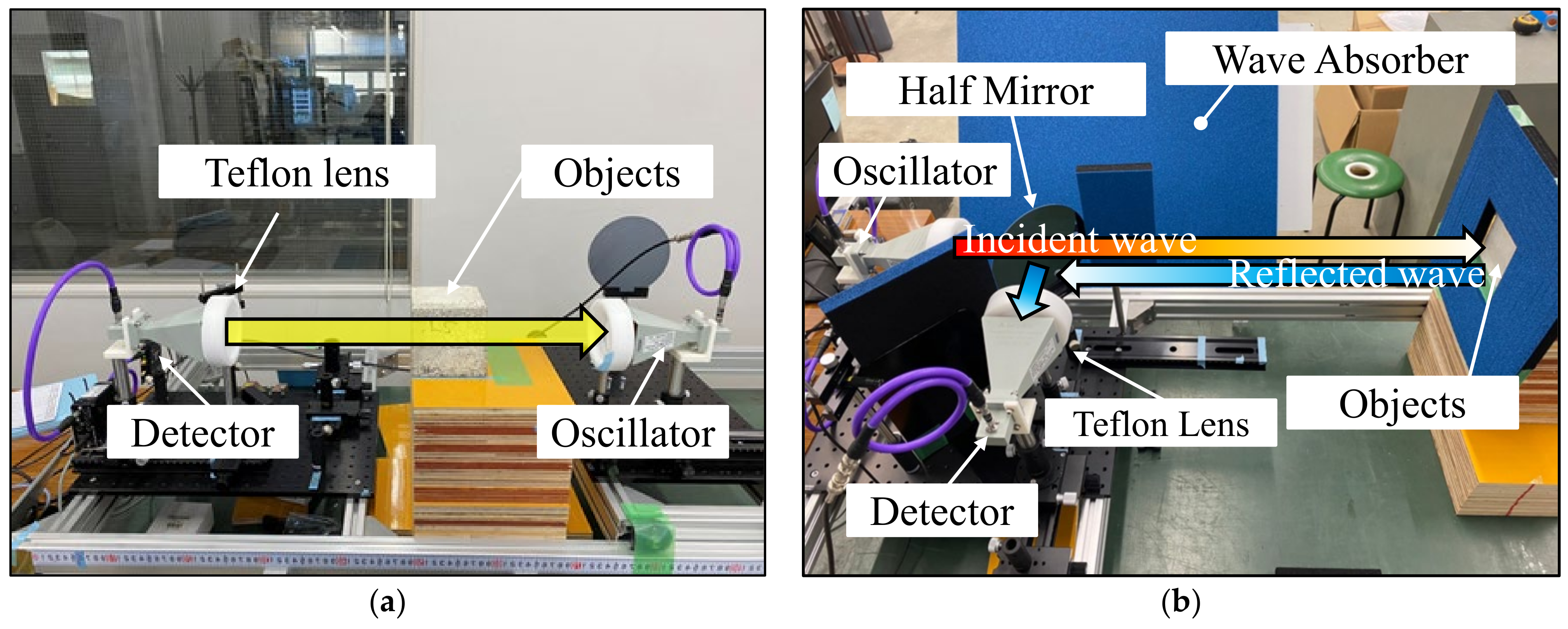
Figure 1 shows schematic diagrams of the (a) transmission and (b) reflection methods in the sub-THz wave optical system. There are two measurement methods for sub-THz wave optics: the transmission method [
20] and the reflection method [
21]. The transmission method requires the oscillator and detector to be placed in a straight line, which is difficult to align in measurements on real structures. Therefore, in this experiment, the reflection method with a half-mirror was mainly employed.
In the reflection method, as shown in
Figure 1b, sub-THz waves emitted from the oscillator with the horn antenna pass through a Teflon lens and a half-mirror. The target object reflects the wave with a specific intensity of reflectance ratio corresponding to the conditions. The detector receives the propagated wave through the half-mirror and Teflon lens. Teflon lenses convert sub-THz waves into collimated beams. The half-mirror plays the role of straight transmitting the incident wave and reflecting to change the angle of the reflected wave from the target specimen.
Table 1 shows the specifications of the sub-THz wave optical system used in this study.
Here, reflectivity is defined in terms of Equation (1) below. The numerator is the absolute value of the reflection intensity as measured with an oscilloscope. The denominator is the absolute value of the reflection intensity as measured with an aluminum plate, which is considered to have 100% reflection or low electromagnetic wave loss. In general, reflectivity is the ratio of reflected energy to incident energy when the incident is perpendicular to an object. However, the sub-THz waves used in this study include several unclear aspects such as the amount of the incidence, reflection, and scattering. Therefore, the reflectivity was calculated using Equation (1).
3. Experimental Outlines
3.1. Influence of Measurement Conditions of Optical System Equipment (STEP1)
3.1.1. Attenuation Effects by Measurement Distance
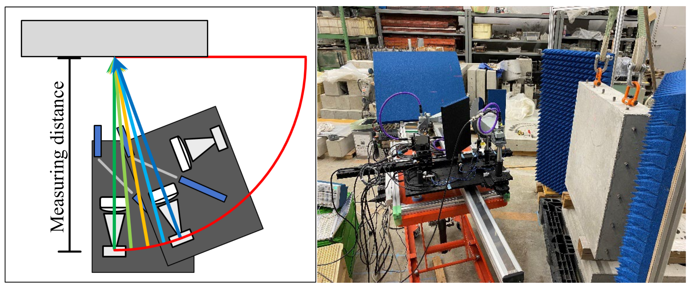
In general, electromagnetic waves are attenuated by atmospheric moisture and air density. Therefore, the farther the distance to the target object, the lower the measured intensity. In addition, the energy required depends on the depth of the defect to be detected. Thus, it is necessary to determine an appropriate emitting intensity according to the distance. In order to understand the electromagnetic characteristics of sub-THz waves, the attenuation effect of sub-THz waves with distance was measured with the transmission and reflection methods. The employed measurement frequencies ranged from 8.5 to 12.5 GHz at 0.5 GHz intervals. For the transmission method, the measurement distance was 610 to 3000 mm at 10 mm intervals. For the reflection method, the measurement distance was 420 to 650 mm at 5 mm spacing, 650 to 1000 mm at 10 mm spacing, and 1000 to 3000 mm at 500 mm spacing.
The measurable strength limit of the sensor used in the detector is approximately 2000 mV. In addition, there is a risk that a higher intensity can exceed the intensity limit due to interference and other effects. Therefore, sub-THz waves were oscillated with an output of 18.5 dBm to obtain an intensity of 1000 mV at a measurement distance of 420 mm for both the transmission and reflection methods. Since electromagnetic waves generally diffuse with distance, evaluation on a logarithmic axis is desirable. Therefore, we substituted the obtained intensity (mV) into Equation (2) to obtain and evaluate the radio wave intensity.
where,
is the converted intensity (dBm), and
is the measured intensity (mV).
3.1.2. Irradiation Range
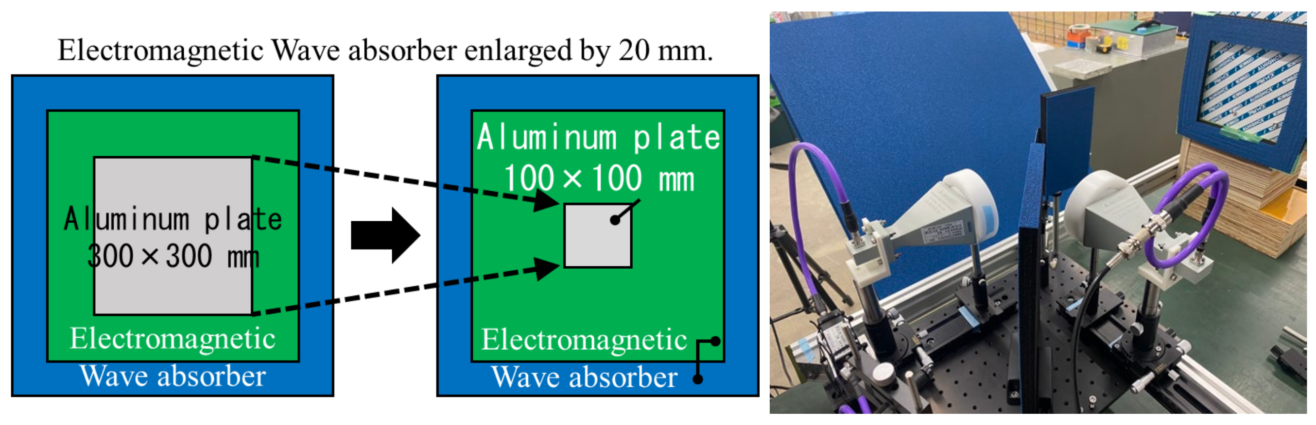
In general, electromagnetic waves diffuse with distance even when polarized into a collimated beam using the Teflon lens. Therefore, the irradiation range according to distance was experimentally investigated.
Figure 2 shows a schematic diagram of the irradiation range measurement. The measurement distance is from 600 to 2400 mm, with the interval of 600 mm. The frequency range was 8.5 to 12.5 GHz. The measurement target to be measured was a 300 × 300 mm plate made of an aluminum alloy (A5052 according to JIS H 4000:2022 “Aluminium and aluminium alloy sheets, strips and plates” of Japan Industrial Standards [
26], corresponding to AlMg2.5 of ISO 209 [
27]) with a high reflectance and thickness accuracy of ±0.05 mm or less. The blue and green areas shown in
Figure 2 represent electromagnetic wave absorbers based on urethane foam, possessing absorption performance for frequencies ranging from 0.6 to 50 GHz. The purpose of the blue absorber was to eliminate the influence on the measurement results caused by the divergence of electromagnetic waves reflected by the surrounding environment. The green absorber was placed in front of the 300 × 300 mm aluminum plate to examine the irradiation range. The green absorber was enlarged by 20 mm each time to investigate the irradiation range based on the attenuation of intensity. The minimum visible size of the target aluminum plate was set to 100 × 100 mm. The reflectivity R
ir was calculated using Equation (3).
3.1.3. Measurement Angle
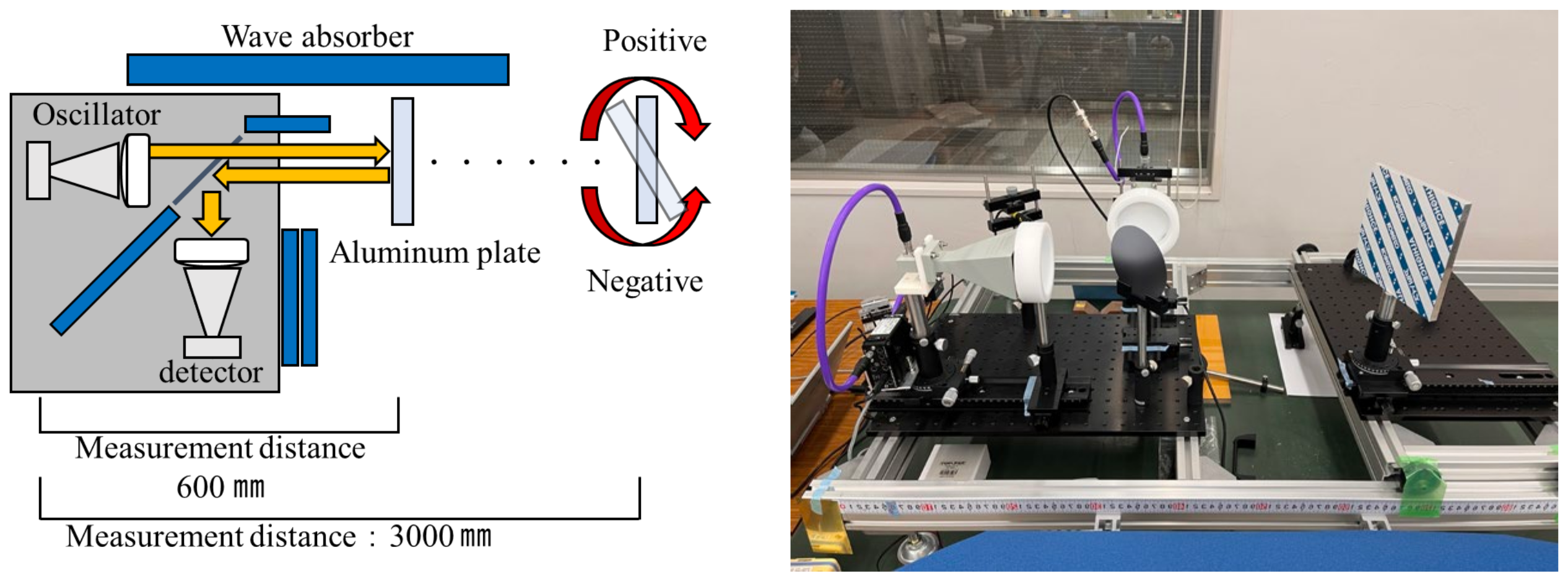
When measuring actual building structures, the measurement environment, including the location conditions of the target structures, often precludes the possibility of conducting measurements directly from the front. Therefore, this section aims to experimentally verify the influence of the measurement angle. Measurements were conducted using an aluminum plate to simulate the target object.
Figure 3 shows a schematic diagram of the measurement to assess the effect of angles. The aluminum plate was rotated by 1
in each direction, with clockwise rotation as positive and counterclockwise rotation as negative. The measurement distance ranged from 1200 to 2400 mm, with measurements taken at 600 mm intervals. The reflectivity R
an was calculated using Equation (4).
3.2. Determine Water Content of Concrete (STEP2)
Outlines of Concrete Specimen
In this step of the process, concrete specimens were prepared to measure their water content.
Table 2 shows the mix proportion of the concrete specimens. Tap water was used as mixing water (W). Ordinary Portland cement (density: 3.16 g/cm
3) was used for cement (C). The fine aggregate (S) was land sand (density: 2.58 g/cm
3), and the coarse aggregate (G) was crushed hard sandstone with a size from 5 to 20 mm (density: 2.65 g/cm
3). In Japan, concrete buildings typically employ concrete with a compressive strength ranging from 18 to 45 N/mm
2. The average water–cement ratio corresponding to these compressive strengths is approximately 50 to 58%; our study utilized concrete with a W/C ratio of 50 to 58%.
The geometries of the specimens were cube types of 100 × 100 × 100 and 200 × 200 × 200 mm, and wall types of 780 × 780 × 150 mm. The specimens were demolded at 7 days from casting and cured in water until 28 days of age. The 200 mm cube specimens were then cut into plate specimens with a thickness of 30 and 50 mm using a concrete saw. All specimens were dried at 105 °C for 2 weeks to define the absolute dried condition. For the air-dried condition, the specimens after drying were maintained in a thermostatic chamber at 20 °C and 60% humidity. Moreover, for the wet condition, the specimens after drying were allowed to absorb moisture in a desiccator at 20 °C and 100% humidity.
The 100 mm cube specimens were subjected to three levels of water content: dry (0.4% water content), air-dry (2.0% water content), and wet (4.3% water content). The water content of the actual structure tends to increase from the surface towards the interior. Therefore, the 200 × 200 × 30 and 200 × 200 × 50 mm specimens were allowed to absorb water from the cut surfaces to simulate the water content trend of the actual structure.
Here, measurements were conducted using frequencies of 9.4, 10.9, 11.5, and 12.3 GHz, where a preliminary investigation confirmed a trend of increasing the reflectance with the higher water content [
28]. Measurements were carried out at a 900 mm distance.
In case of the wall specimens, the risk of corrosion in the reinforcing rebars inside concrete increases with the high water content surrounding them. To simulate the corrosive environments at any given point within the concrete specimens, we adopted the water injection method to control the water content. The water content can be adjusted by holes which are 20 mm in diameter and 100 mm deep; these holes were drilled at 100 mm intervals from the center of the specimen. Water was injected to an area of approximately 300 × 300 mm from the side opposite to the measurement surface of the specimen to partially change the water content. Aluminum tape was attached to the left edge of the specimen to serve as the reflectivity reference.
3.3. Effect of Rebar in Reinforced Concrete Members (STEP3)
3.3.1. Outlines of Reinforce Concrete Specimen
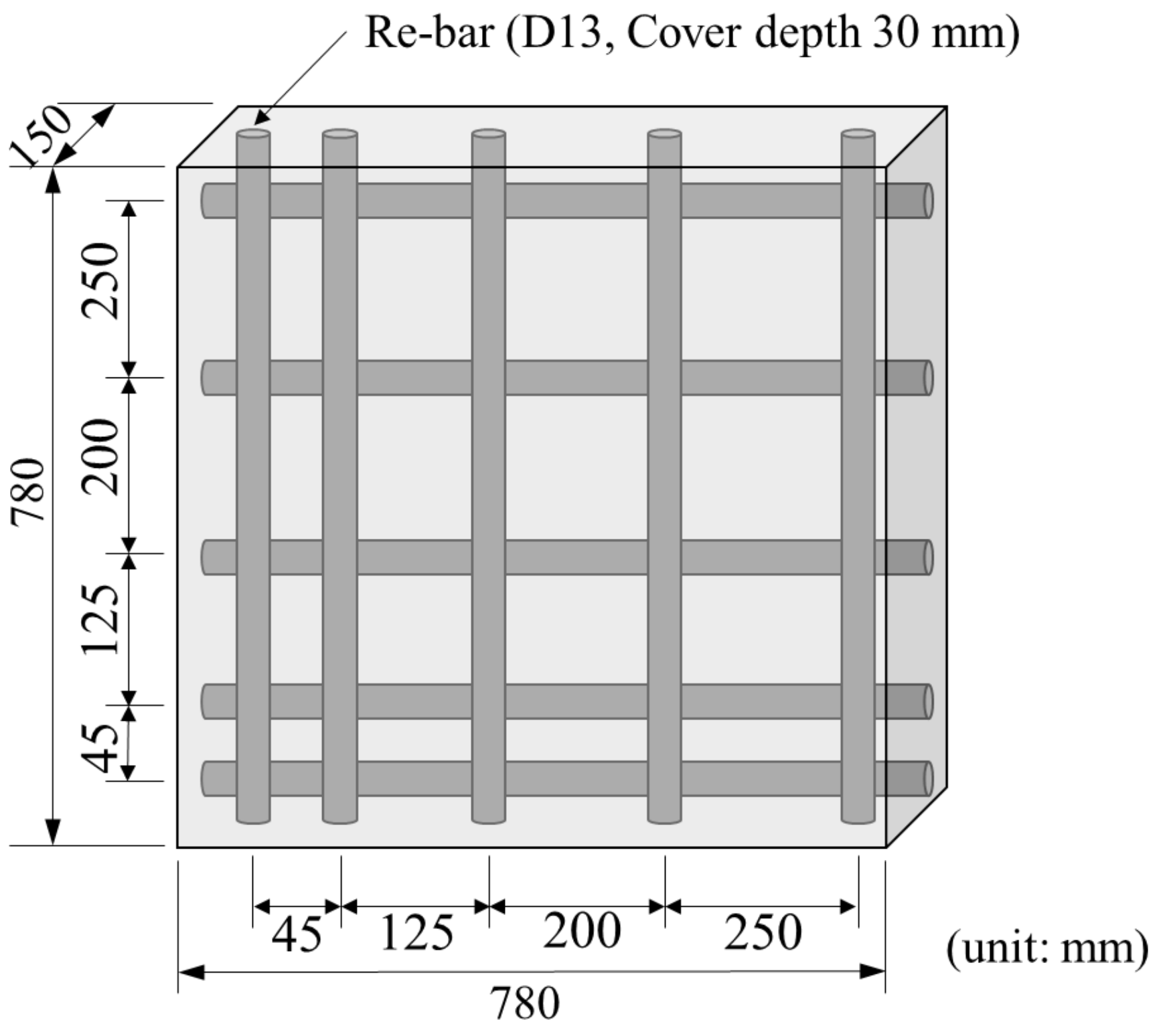
In this step of the process, reinforced concrete specimens were used to investigate the effect of rebar within concrete on the measurement results. The specimens were made of concrete with a water–cement ratio of 58% (shown in
Table 2).
Figure 4 shows an overview of the reinforced concrete member. In this study, the influence of the reinforcement condition on the water content estimation has been considered as an experimental parameter. Therefore, the over-dense to sparse arrangement was employed. The geometry of the wall specimen was 780 × 780 × 150 mm with D13 deformed bars embedded at a cover depth of 30 mm and spacing of 40, 125, 200, and 250 mm to ensure non-uniform reinforcement. The longitudinal rebars were placed at a cover thickness of 30 mm.
3.3.2. Experimental Procedures
The measurement distance was 900 mm, and the frequency was 12.3 GHz, which is considered optimal for determining the water content of concrete surfaces as described below. The measurement angle was set at 90 degrees from the front of the specimen, which is directly in front of the specimen. The angle of the optical system was changed by 5 degrees to 15 degrees (the measurement angles: 90, 85, 80, and 75 degrees, as shown in
Figure 5). The optical system was moved at 100 mm intervals in the vertical and horizontal directions to measure each area of the wall specimen, and a total of 42 points were measured (6 rows (A to F) in the vertical direction and 7 (1 to 7) columns in the horizontal direction) to evaluate the water content of the entire concrete wall.
The water content of the specimens was measured using a contact-type electrical resistance water content meter, which can be easily used for measurements by pressing it against the concrete surface. The objective of the employed device was to qualitatively measure the water content. The specimen was dried up to the same measured values of the controlled specimen with the water content of 3.5%.
4. Experimental Results and Discussion
4.1. Influence of Measurement Conditions of Optical System Equipment (STEP1)
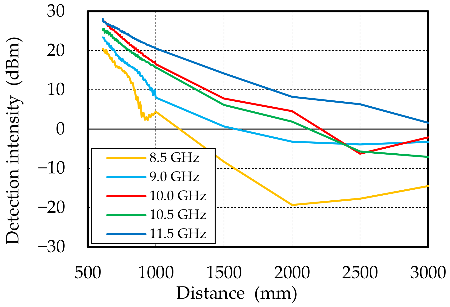
4.1.1. Attenuation Effects by Measurement Distance
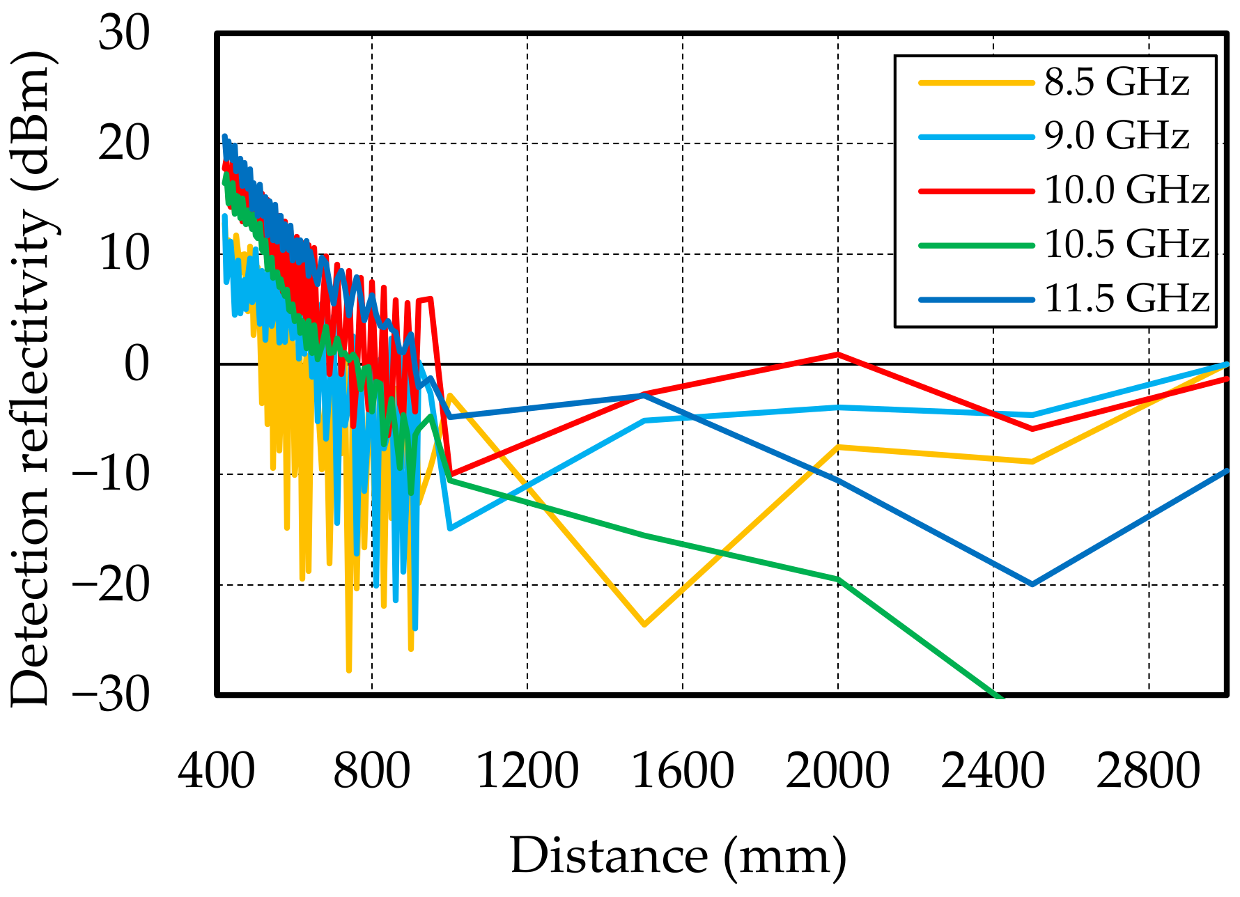
Figure 6 and
Figure 7 show the results of distance attenuation by using the transmission and reflection methods, respectively. For both the transmission and reflection methods, it was confirmed that the intensity attenuates as the measurement distance increases. In the reflection method, the detected intensity attenuates with significant amplitude fluctuations compared to the transmission method. This is due to interference between the incident and reflected waves. In the reflection method, detection intensities higher than the output of 18.5 dBm were obtained at 10, 0.5, and 11.5 GHz up to a measurement distance of approximately 600 mm. This is presumably due to the interference between the incident and reflected waves, and also because the detection sensitivity of the detector increases with the high frequency.
4.1.2. Relationship between the Measurement Distance and Irradiation Area
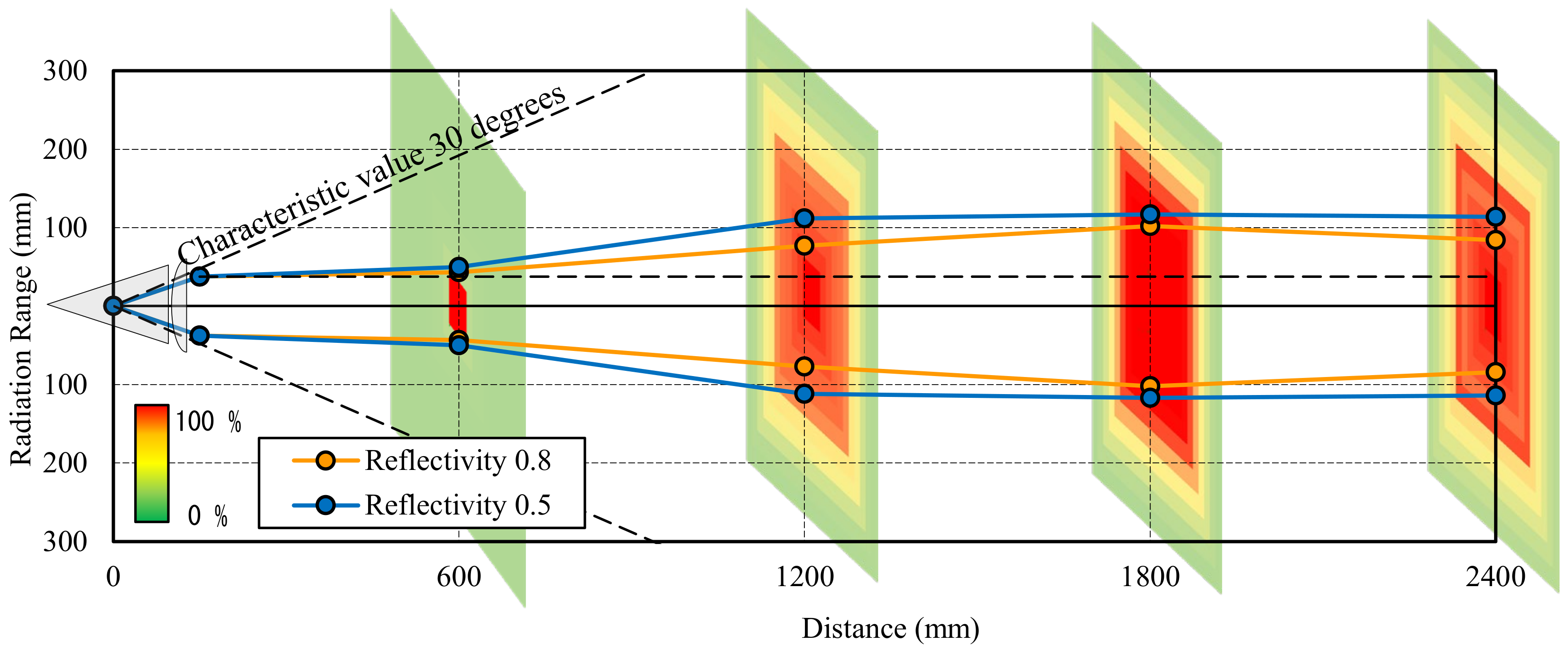
Figure 8 shows the irradiation range according to the measurement distance. The scale bar of reflectivity R
ir was calculated using Equation (3). A high R
ir indicates a red color, and a large red area indicates the diffusion of the sub-THz waves. In contrast, green indicates a low R
ir, and a large green area means high directivity. In the case where the measurement distance was 600 mm, a high reflectivity was obtained in the 100 × 100 mm range, confirming that the Teflon lenses were able to provide generally parallel beams. When the measurement distance is more than 1200 mm, the electromagnetic wave diffuses down to about 200 mm in diameter, and the irradiation area is expanded.
When this method is practically used on-site, a greater distance to the target structure building might be needed. Therefore, it is essential to examine the dispersion of the sub-THz wave at further measurement distances.
4.1.3. Relationship between the Measurement Distance and Measurement Angle
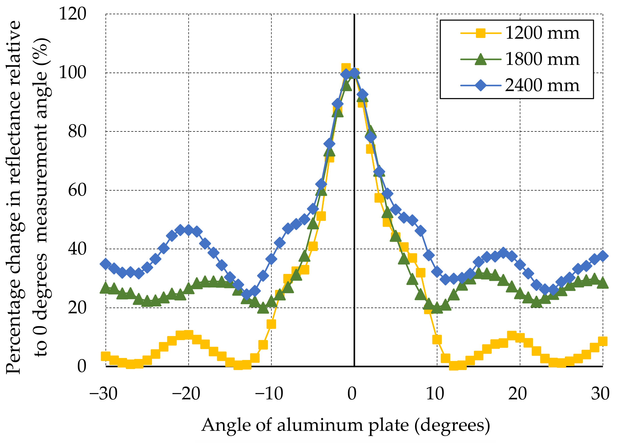
Figure 9 shows the effect of the measurement angle. The positive and negative rotation angles produced a reflectivity R
an that was symmetrical with respect to 0 degrees. Within an angle range of ±2 degrees, R
an shows approximately more than 80%. Furthermore, within an angle range of ±5 degrees, a linear decreasing trend of R
an is observed. Beyond these angles, fluctuations in R
an due to the interference of sub-THz waves can be confirmed.
It is therefore predicted that the oblique incidence of sub-THz waves at different measurement angles will reduce the accuracy of detection. Therefore, the decrease in reflectance due to a 1 deviation in measurement angle must be fully considered, and further studies on the allowable range of measurement angles and correction methods are needed.
4.2. Study to Determine Water Content of Concrete (STEP2)
4.2.1. Relationship between Unit Volume Water Content and Reflectance
The results of the measurements of concrete with different water contents suggest that in the transmission method, the strength decreases as the water content increases, while in the reflection method, as the water content increases, the reflected strength also tends to increase [
28].
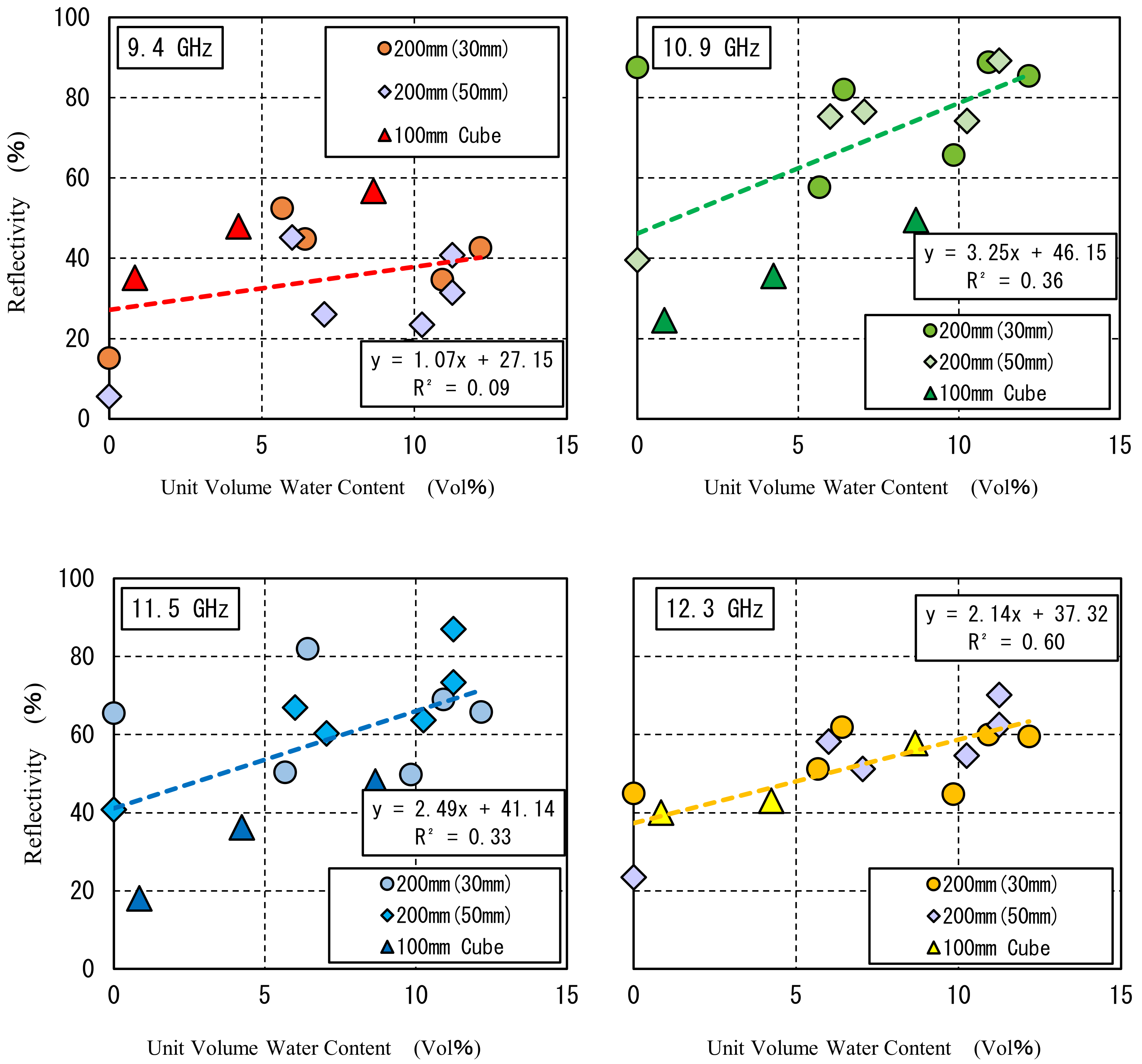
Figure 10 shows the relationship between the unit volume water content and reflectivity calculated using Equation (1). The result of 9.4 GHz shows a linear trend between the unit volume water content and reflectivity when the three specimens are evaluated individually. However, the relationship includes a large variation. The reflectivity tended to increase as the unit volume water content increased, regardless of the test specimen. Within the range of this experiment, the variation in the reflectivity tended to decrease as the frequency increased, with the smallest variation at 12.3 GHz. It can be inferred from this that the measurement at 12.3 GHz is the most suitable among the employed frequencies for determining the water content at the cover concrete.
4.2.2. Estimation of Water Content Distribution at the Water Inlet Location
The results suggest that it may be possible to identify the location of the water injection and the location of the dry state in the transmission method [
20]. The same results are expected to be obtained in the present study; however, they do not necessarily coincide with those obtained for a specimen simulating a real structure. Therefore, experiments were conducted under conditions in which the moisture content and reflected intensity could be determined, and the intensity obtained from the reflection method was used to stockpile basic data for the water content evaluation as follows.
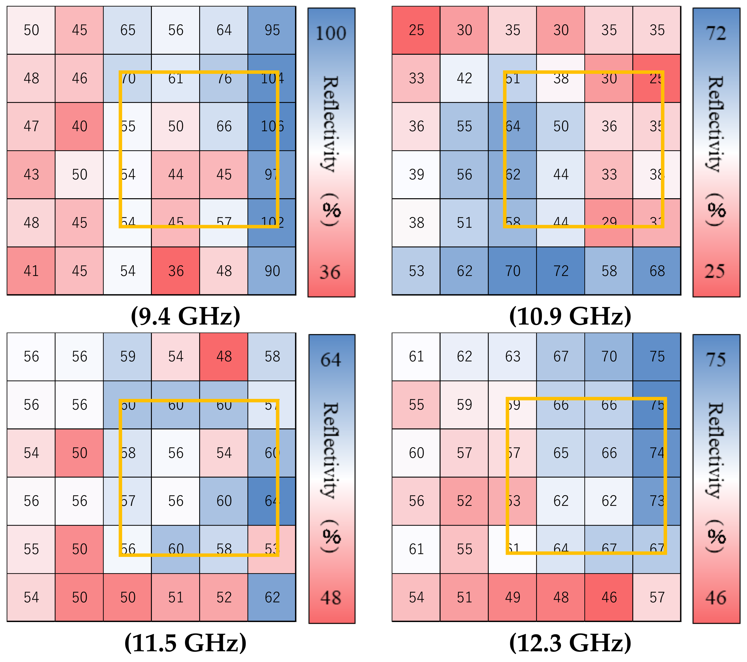
Figure 11 shows the estimated distribution of water content at the locations of the water injections. The yellow framed areas indicate the locations where water was injected from the backside of the specimen. The color scale of this figure shows that the reflectivity increases in the order of red, white, and blue.
At the measurement results with 9.4 GHz, high reflectivity was observed at the right end of the specimens and low reflectivity was observed at the left side of the specimens; at 10.9 GHz, no high reflectivity was observed at the water injection point and high reflectivity was observed at the center and bottom of the specimens; at 11.5 and 12.3 GHz, high reflectivity was observed near the water injection point, suggesting that water was detected. These results suggest that differences in the understanding of water distribution were obtained due to the relationship between the penetration depth of the injected water and the wavelength of the frequency, as well as differences in the transmittance of the frequency.
4.3. Effect of Measurement Angle on Reinforced Concrete Members (STEP3)
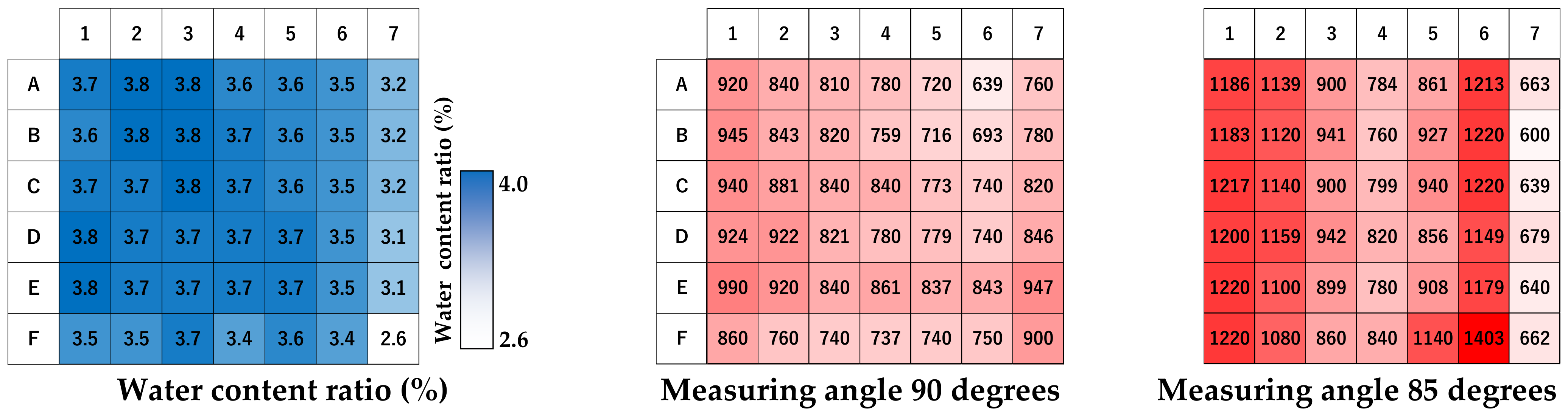
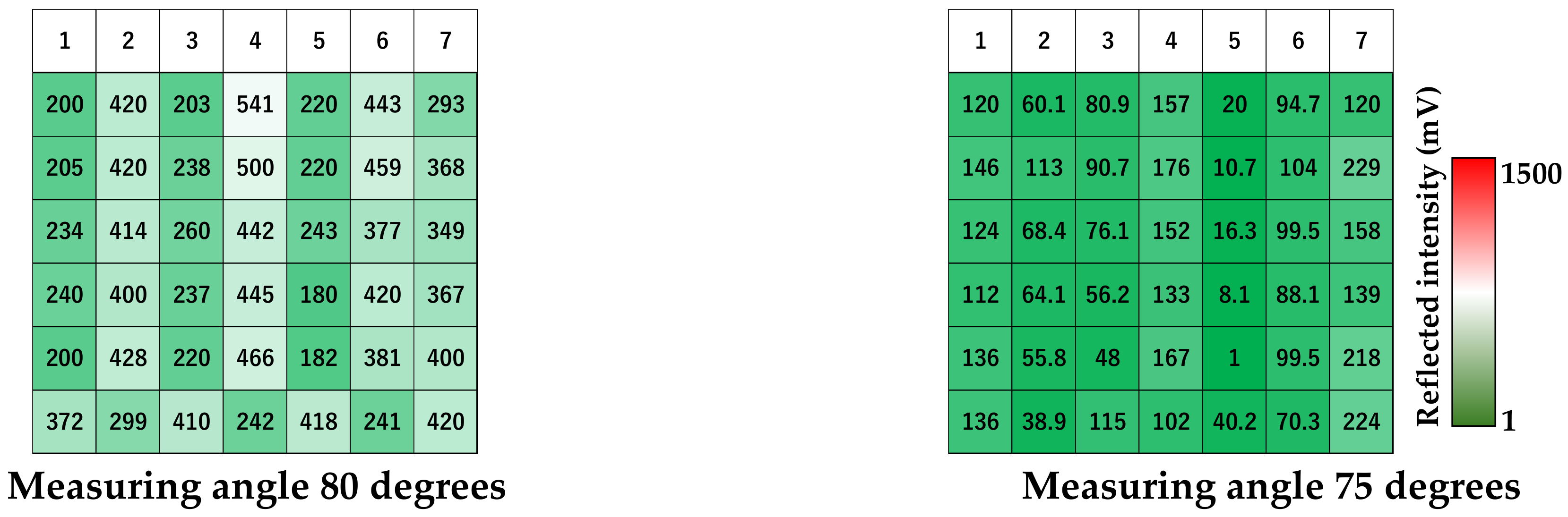
Figure 12 shows the intensity distribution of the measured angles of the non-uniformly reinforced concrete specimen measured using the frequency of 12.3 GHz. The color scale in the figure indicates the ascending order of the detection intensity from green to white to red.
The highest detection intensity was obtained at a measurement angle of 85 degrees, beyond which the detection intensity diminished with a decreasing measurement angle. The distribution of detection intensity at a 90 degrees angle was similar to the distribution of water content. However, no correlation between the detection intensity and water content distribution was noted at the other measurement angles.
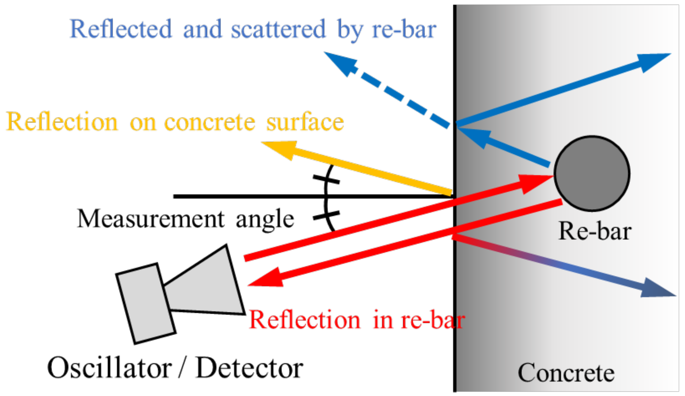
At measurement angles of 85, 80, and 75 degrees, detection intensities resembling vertical stripes were observed, predominantly at the locations corresponding to the rebar, indicating its detection. Although 12.3 GHz has no significant penetrating performance through concrete,
Figure 13 suggests that the reflected sub-THz waves from the concrete surface follow a different propagation path compared to the incident waves, leading to the reduced detected intensity. However, the sub-THz waves that penetrated the concrete were reflected by the rebar and traced the same path as the incident wave, which is assumed to have resulted in a clear difference in detection intensity.
5. Conclusions
The following findings were obtained regarding the selection of frequencies and the applicability of the selected frequencies for the purpose of determining the water content of concrete from a distance using sub-THz waves:
- (1)
The effects of the measurement angle were systematically investigated: when the angle between the object and the measurement device was established at 90 degrees as the reference, variations of ±2 degrees resulted in a reduction of up to 80% in reflection intensity. This phenomenon exhibited a linear trend up to a deviation of ±5 degrees; beyond a deviation of ±10 degrees, an accurate assessment of the object’s condition might be compromised due to the effects of secondary reflections and electromagnetic wave scattering. These findings suggest that, for the purpose of evaluating the condition of the concrete based on the reflectivity data, the measurement angle should ideally be maintained within a range of ±5 degrees from the 90-degree reference.
- (2)
The irradiation range of the sub-THz wave differs depending on the measurement distance. The farther the measurement distance, the larger the irradiation range, and a more diffuse electromagnetic wave was observed. However, it was confirmed that the light was generally focused at about 200 × 200 mm.
- (3)
In the estimation of the water content of concrete using the reflection method, the trend of increasing reflectance with increasing water content was confirmed by selecting frequencies (9.4, 10.3, 11.5, and 12.3 GHz). The results indicate that when moisture content distribution is generated in concrete wall members, the selected frequencies may be used to identify locations with high water content.
- (4)
Upon conducting measurements of the reinforced concrete wall specimens from varying angles, it was discerned that the relative impact of the concrete surface layer as opposed to that of the reinforcing bars exhibited variance at a measurement angle of approximately 90 ± 10 degrees, contingent upon the specific angle of measurement employed. This variance is ostensibly attributed to the propagation pathways of the reflected waves. Consequently, the findings indicate that, for the purpose of assessing the moisture content within the concrete surface layer, the measurement angle ought to be meticulously maintained within a range of 90 ± 5 degrees.
In this paper, the potential of using sub-THz waves for estimating the water content of concrete surface layers from a distance was demonstrated. The use of sub-THz waves is not limited to estimating water content but is also applicable for identifying cracks inside concrete caused by reinforcing bar corrosion, fire loading, and so on. However, since studying cracks requires measuring defects smaller than the wavelength of the frequency used, it is crucial to understand electromagnetic wave characteristics, including interference, scattering, and absorption by the rebar and propagation paths.
Therefore, as a direction for future research, to precisely obtain information on the interior of concrete, especially targeting cracks, it is essential to comprehend the electromagnetic wave characteristics, construct a measurement system that can disregard the effects of interference, and process information using AI.
Author Contributions
Conceptualization, A.T. and T.N.; methodology, S.F. and T.T.; validation, K.A. and C.K.; formal analysis, K.A.; investigation, K.A.; data curation, K.A.; writing—original draft preparation, A.T.; writing—review and editing, T.N.; visualization, K.A.; supervision, T.N.; project administration, T.N.; funding acquisition, A.T. All authors have read and agreed to the published version of the manuscript.
Funding
The APC was funded by JAEA Nuclear Energy S&T and Human Resource Development Project Grant Number JPJA21P21458909.
Data Availability Statement
Data are contained within the article.
Conflicts of Interest
Koji Arita was employed by Constec Engi,Co. The remaining authors declare that the research was conducted in the absence of any commercial or financial relationships that could be construed as a potential conflict of interest.
References
- Architectural Institute of Japan (AIJ). Recommendations of Durability Design and construction Practice of Reinforced Concrete Buildings, 2nd ed.; AIJ: Tokyo, Japan, 2016. (In Japanese) [Google Scholar]
- Beushausen, H.; Luco, L.F. Performance-Based Specifications and Control of Concrete Durability: State-of-the-Art Report RILEM TC 230-PSC. In Performance-Based Specifications and Control of Concrete Durability: State-of-the-Art Report RILEM TC 230-PSC; Springer: Berlin/Heidelberg, Germany, 2015; Volume 18, pp. 1–373. [Google Scholar] [CrossRef]
- Kazemi, M.; Madandoust, R.; de Brito, J. Compressive strength assessment of recycled aggregate concrete using Schmidt rebound hammer and core testing. Constr. Build. Mater. 2019, 224, 630–638. [Google Scholar] [CrossRef]
- ASTM C1383-15:2022; Standard Test Method for Measuring the P-Wave Speed and the Thickness of Concrete Plates Using the Impact-Echo Method. American Society for Testing and Materials (ASTM): West Conshohocken, PA, USA, 2022.
- Kumar, A.; Raj, B.; Kalyanasundaram, P.; Jayakumar, T.; Thavasimuthu, M. Structural integrity assessment of the containment structure of a pressurised heavy water nuclear reactor using impact echo technique. NDT E Int. 2002, 35, 213–220. [Google Scholar] [CrossRef]
- Zheng, L.; Cheng, H.; Huo, L.; Song, G. Monitor concrete moisture level using percussion and machine learning. Constr. Build. Mater. 2019, 229, 117077. [Google Scholar] [CrossRef]
- Lawson, I.; Lawson, I.; Danso, K.A.; Odoi, H.C.; Adjei, C.A.; Quashie, F.K.; Mumuni, I.I.; Ibrahim, I.S. Non-Destructive Evaluation of Concrete using Ultrasonic Pulse Velocity. Res. J. Appl. Sci. Eng. Technol. 2011, 3, 499–504. Available online: https://www.researchgate.net/publication/265144573 (accessed on 10 February 2024).
- Choi, P.; Kim, D.-H.; Lee, B.-H.; Won, M.C. Application of ultrasonic shear-wave tomography to identify horizontal crack or delamination in concrete pavement and bridge. Constr. Build. Mater. 2016, 121, 81–91. [Google Scholar] [CrossRef]
- Hugenschmidt, J.; Mastrangelo, R. GPR inspection of concrete bridges. Cem. Concr. Compos. 2006, 28, 384–392. [Google Scholar] [CrossRef]
- Chang, C.W.; Lin, C.H.; Lien, H.S. Measurement radius of reinforcing steel bar in concrete using digital image GPR. Constr. Build. Mater. 2009, 23, 1057–1063. [Google Scholar] [CrossRef]
- Laurens, S.; Balayssac, J.P.; Rhazi, J.; Klysz, G.; Arliguie, G. Non-destructive evaluation of concrete moisture by GPR: Experimental study and direct modeling. Mater. Struct. 2005, 38, 827–832. [Google Scholar] [CrossRef]
- Wiwatrojanagul, P.; Sahamitmongkol, R.; Tangtermsirikul, S.; Khamsemanan, N. A new method to determine locations of rebars and estimate cover thickness of RC structures using GPR data. Constr. Build. Mater. 2017, 140, 257–273. [Google Scholar] [CrossRef]
- Liu, H.; Lin, C.; Cui, J.; Fan, L.; Xie, X.; Spencer, B.F. Detection and localization of rebar in concrete by deep learning using ground penetrating radar. Autom. Constr. 2020, 118, 103279. [Google Scholar] [CrossRef]
- Janků, M.; Březina, I.; Grošek, J. Use of Infrared Thermography to Detect Defects on Concrete Bridges. Procedia Eng. 2017, 190, 62–69. [Google Scholar] [CrossRef]
- Cheng, C.-C.; Cheng, T.-M.; Chiang, C.-H. Defect detection of concrete structures using both infrared thermography and elastic waves. Autom. Constr. 2008, 18, 87–92. [Google Scholar] [CrossRef]
- Omar, T.; Nehdi, M.L. Remote sensing of concrete bridge decks using unmanned aerial vehicle infrared thermography. Autom. Constr. 2017, 83, 360–371. [Google Scholar] [CrossRef]
- Michel, A.; Pease, B.J.; Geiker, M.R.; Stang, H.; Olesen, J.F. Monitoring reinforcement corrosion and corrosion-induced cracking using non-destructive x-ray attenuation measurements. Cem. Concr. Res. 2011, 41, 1085–1094. [Google Scholar] [CrossRef]
- Skarżyński, Ł; Tejchman, J. Experimental Investigations of Fracture Process in Concrete by Means of X-ray Micro-computed Tomography. Strain 2016, 52, 26–45. [Google Scholar] [CrossRef]
- Lukovic, M.; Schlangen, E.; Ye, G.; van Breugel, K. Moisture exchange in concrete repair system captured by X-ray absorption. In Concrete Repair, Rehabilitation and Retrofitting IV; CRC Press: Boca Raton, FL, USA, 2016. [Google Scholar]
- Nishiwaki, T.; Shimizu, K.; Tanabe, T.; Gardner, D.; Maddalena, R. Terahertz (THz) Wave Imaging in Civil Engineering to Assess Self-Healing of Fiber-Reinforced Cementitious Composites (FRCC). J. Adv. Concr. Technol. 2023, 21, 58–75. [Google Scholar] [CrossRef]
- Kobayashi, C.; Nishiwaki, T.; Hara, S.; Tanabe, T.; Oohashi, T.; Hamasaki, H.; Hikishima, S.; Tanaka, A.; Arita, K. Fundamental research on non-destructive testing of reinforced concrete structures using sub-terahertz reflected waves. MATEC Web Conf. 2023, 378, 04007. [Google Scholar] [CrossRef]
- Oyama, Y.; Yamagata, T.; Kariya, H.; Tanabe, T.; Saito, K. Non-destructive Inspection of Copper Corrosion via Coherent Terahertz Light Source. ECS Trans. 2013, 50, 89–98. [Google Scholar] [CrossRef]
- Kariya, H.; Sato, A.; Tanabe, T.; Saito, K.; Nishihara, K.; Taniyama, A.; Oyama, Y. Non-destructive Evaluation of a Corroded Metal Surface Using Terahertz Wave. ECS Trans. 2013, 50, 81–88. [Google Scholar] [CrossRef]
- Nakamura, Y.; Kariya, H.; Sato, A.; Tanabe, T.; Nishihara, K.; Taniyama, A.; Nakajima, K.; Maeda, K.; Oyama, Y. Nondestructive Corrosion Diagnosis of Painted Hot-Dip Galvanizing Steel Sheets by Using THz Spectral Imaging. Corros. Eng. 2014, 63, 411–416. [Google Scholar] [CrossRef]
- Tanabe, T.; Watanabe, K.; Oyama, Y.; Seo, K. Polarization sensitive THz absorption spectroscopy for the evaluation of uniaxially deformed ultra-high molecular weight polyethylene. NDT E Int. 2010, 43, 329–333. [Google Scholar] [CrossRef]
- JIS H 4000:2022; Aluminium and Aluminium Alloy Sheets, Strips and Plates. Japanese Industrial Standards (JIS): Tokyo, Japan, 2022.
- ISO 209:2007; Aluminium and Aluminium Alloys—Chemical Composition. International Organization for Standardization (ISO): Geneva, Switzerland, 2007.
- Arita, K.; Tanaka, A.; Nishiwaki, T. Fundamental Study of Internal Defect Detection by Sub-THz Waves for Long-Range Measurement. Proc. Jpn. Concr. Inst. 2023, 45, 1450–1455. (In Japanese) [Google Scholar]
| Disclaimer/Publisher’s Note: The statements, opinions and data contained in all publications are solely those of the individual author(s) and contributor(s) and not of MDPI and/or the editor(s). MDPI and/or the editor(s) disclaim responsibility for any injury to people or property resulting from any ideas, methods, instructions or products referred to in the content. |
© 2024 by the authors. Licensee MDPI, Basel, Switzerland. This article is an open access article distributed under the terms and conditions of the Creative Commons Attribution (CC BY) license (https://creativecommons.org/licenses/by/4.0/).


 ,
, 


