

Tests and Seismic Response Analysis of Guided-Rail-Type Anti-Tensile Rubber Bearing

Abstract
:1. Introduction
2. Structure of GR&RB
3. Experimental Tests
3.1. Test Specimens
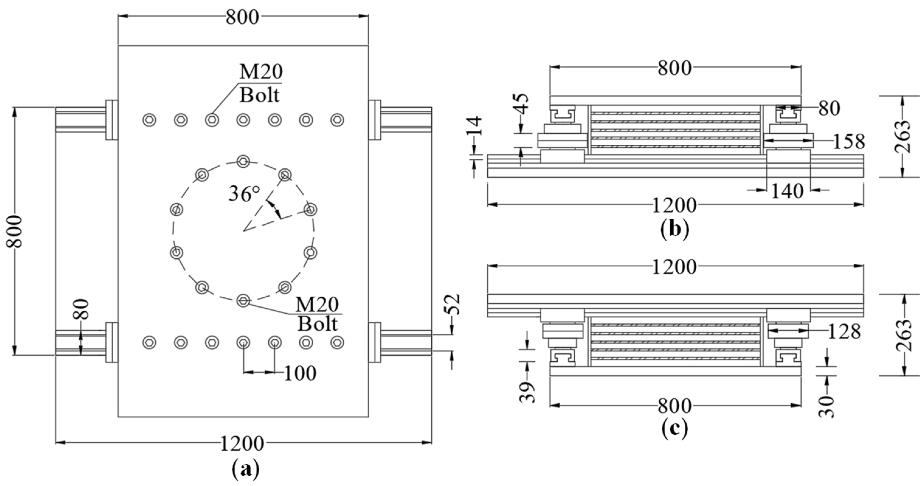
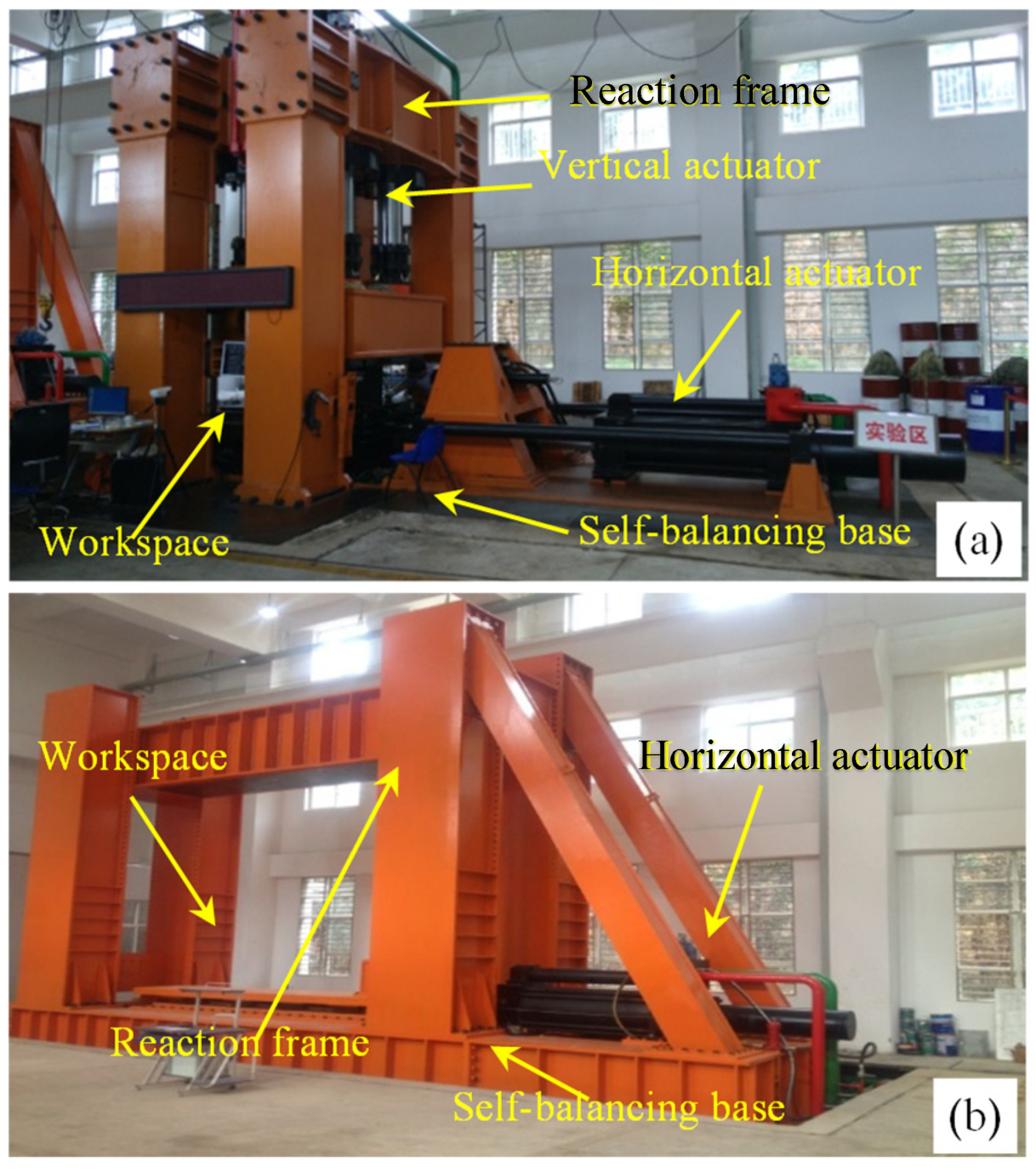
3.2. Test Equipment
3.3. Test Procedure
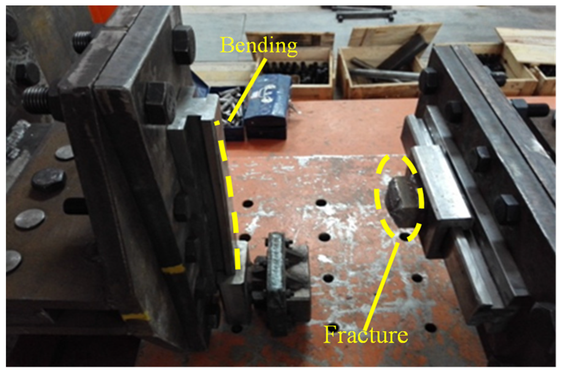
3.4. Test Results
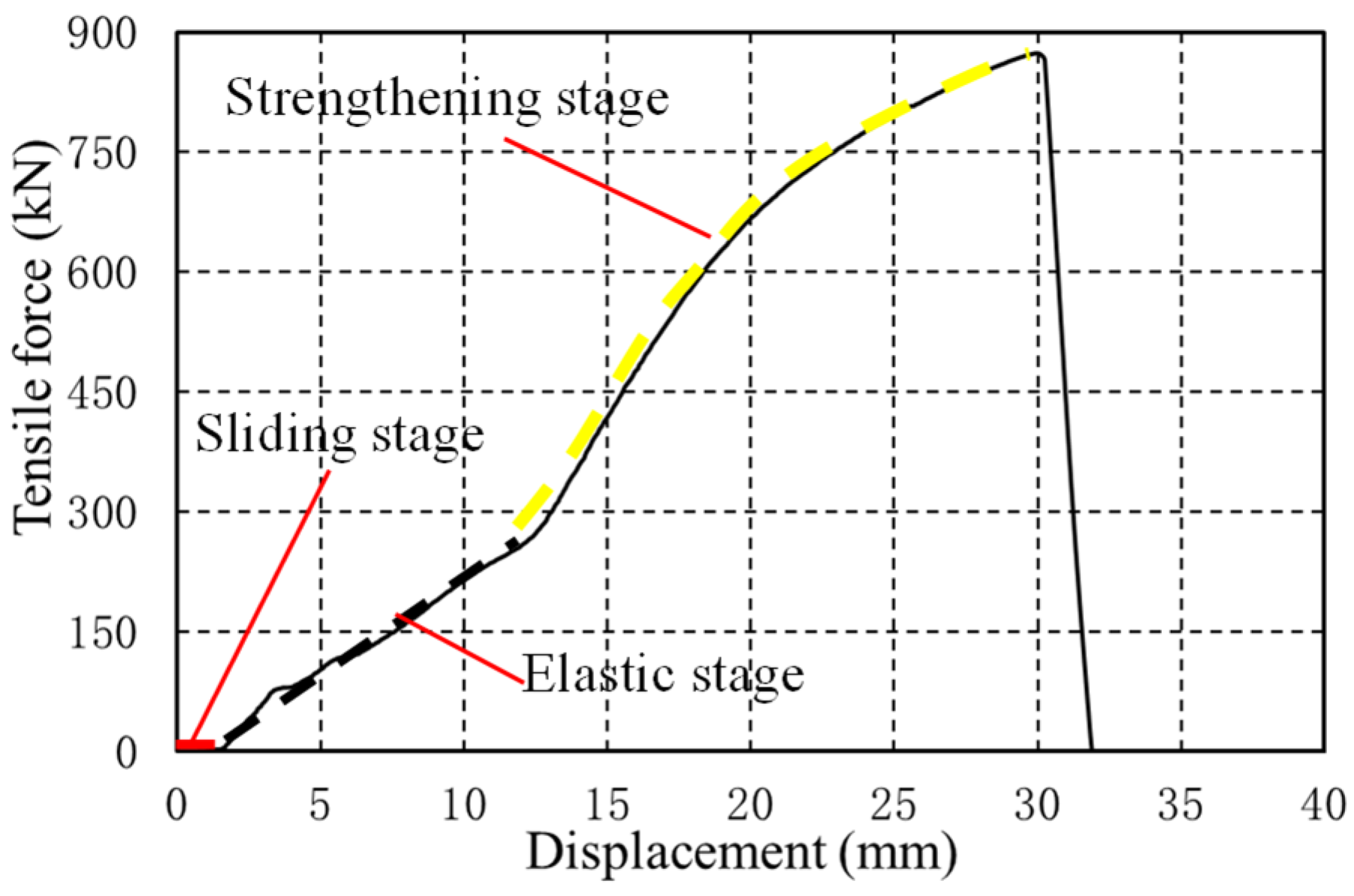
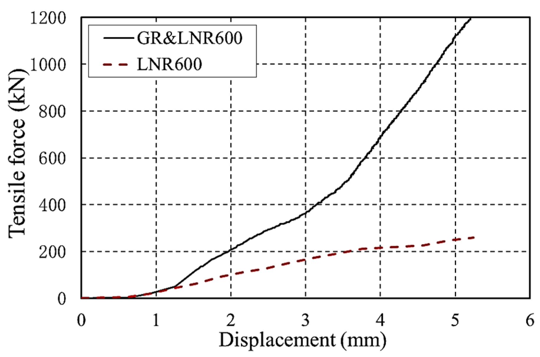
3.4.1. Tensile Properties
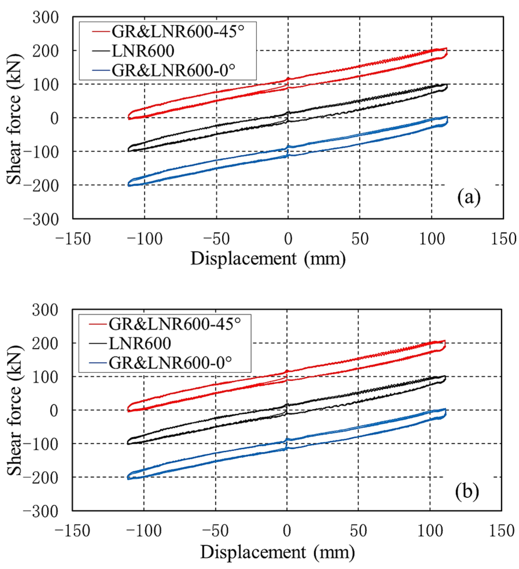
3.4.2. Horizontal Compression–Shear and Tensile–Shear Performance
4. Numerical Analysis of Seismic Response
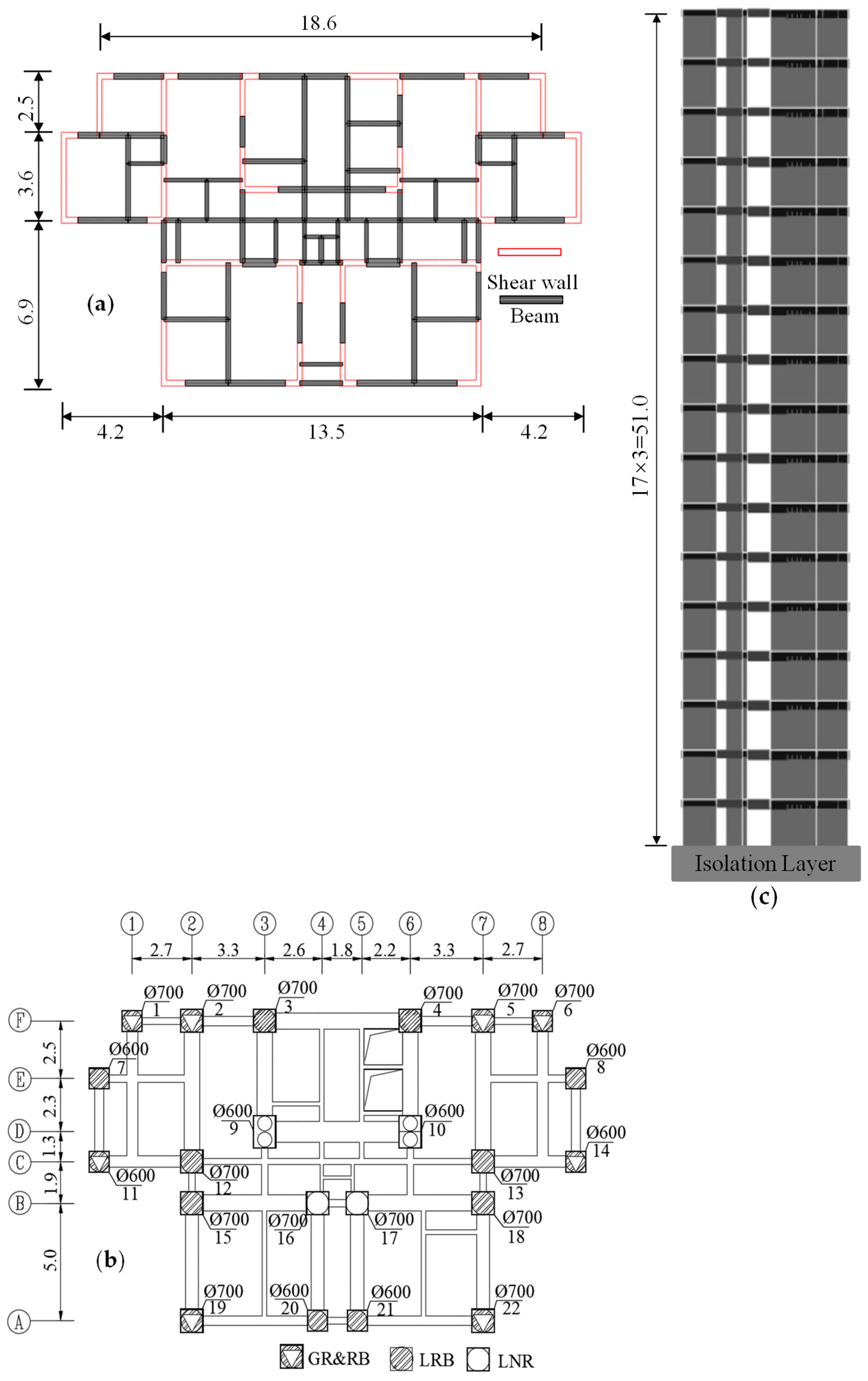
4.1. Building for Numerical Analysis
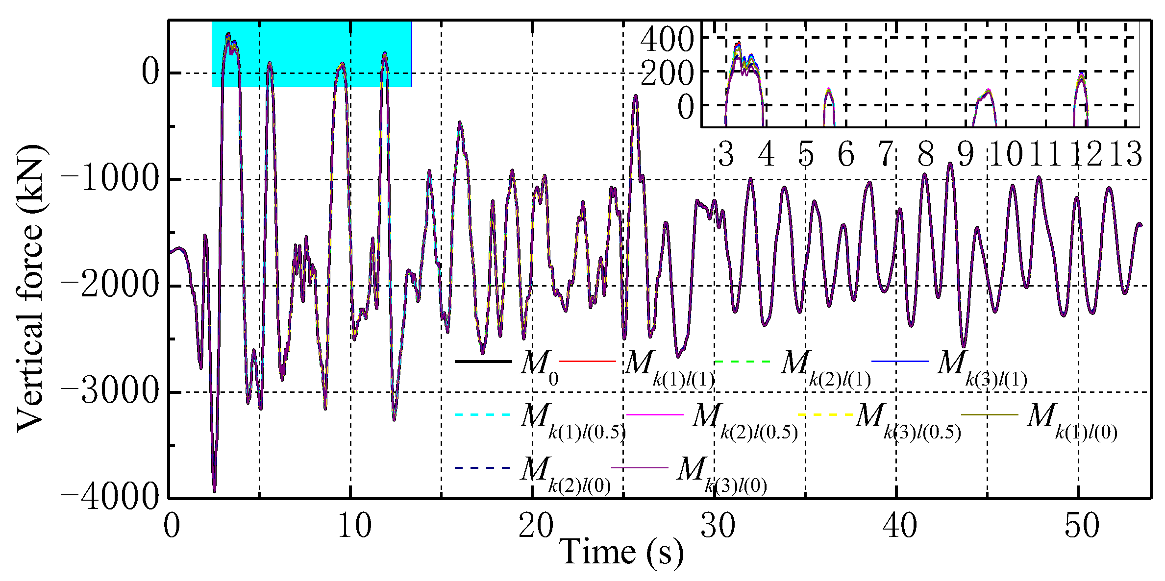
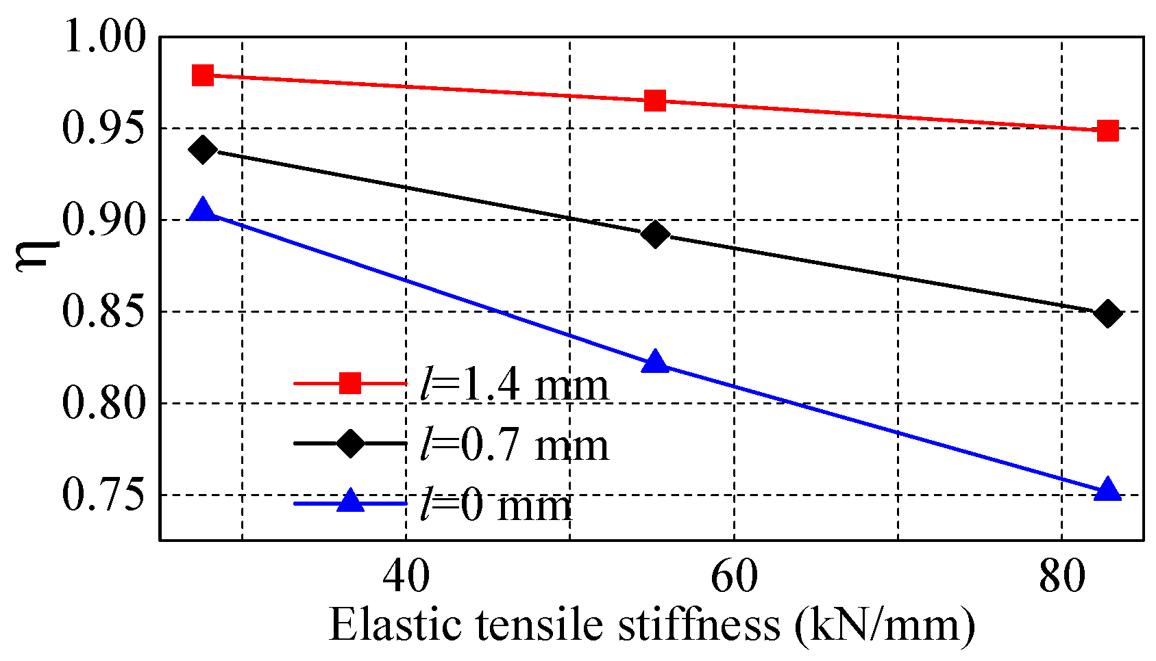
4.2. Tensile Performance of Isolators
5. Conclusions
- (1)
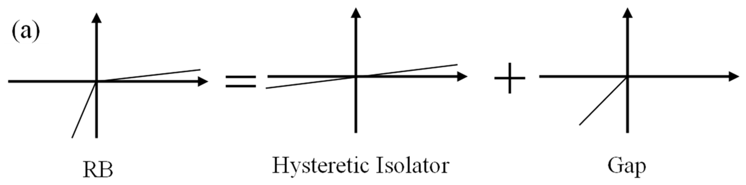
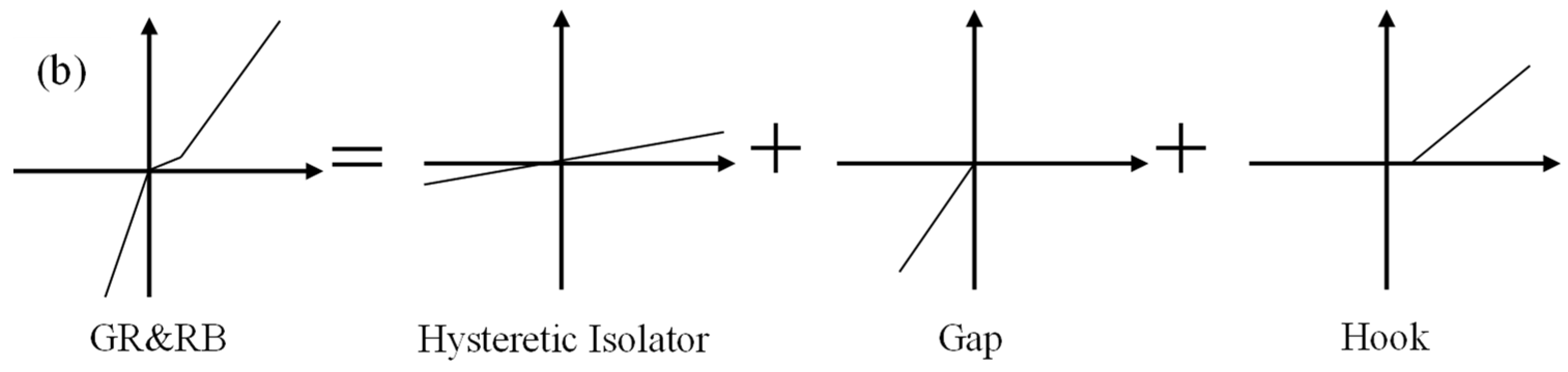
- The presence of clearance results in a slip stage during the initial phase of single GR stretching, thereby enabling the characterization of the GR’s tensile behavior as Hook. Moreover, during finite element simulation, the vertical mechanical behavior of the GR&RB can be effectively represented through the parallel superposition of the hysteretic isolator, gap, and Hook.
- (2)
- Within the elastic tensile range of rubber bearings, the tensile strength of the GR&RB is approximately 4.3 times greater than that of RBs of equivalent scale, underscoring the remarkable tensile capacity of the GR&RB.
- (3)
- The horizontal mechanical performance of the GR&RB exhibits almost complete independence with respect to the angle of the guide rail and the loading direction, thereby equating the horizontal mechanical performance of the GR&RB to that of RBs of similar dimensions.
- (4)
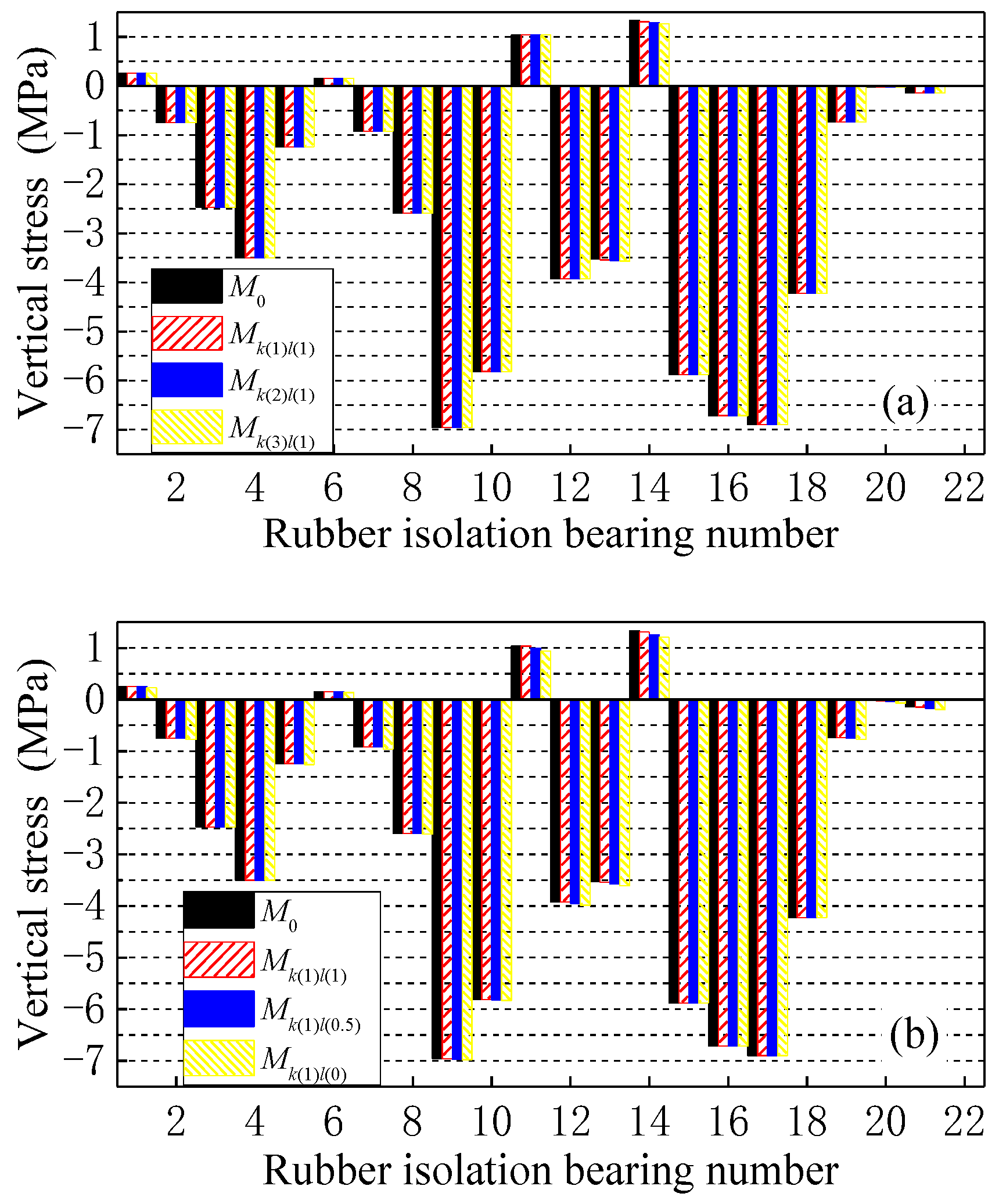
- The implementation of the GR&RB leads to a reduction in the level of tensile stress experienced by the rubber isolators. This reduction signifies that the utilization of the GR&RB diminishes the likelihood of failure related to overturning in seismic isolation structures by enhancing the tensile performance of the bearings. Furthermore, both an increase in the elastic tensile stiffness and a decrease in the open value of the GR can elevate the tensile strength of the GR&RB, with the optimal effect achieved through an increase in the elastic tensile stiffness while simultaneously decreasing the open value of the GR.
Author Contributions
Funding
Data Availability Statement
Acknowledgments
Conflicts of Interest
References
- Skinner, R.I.; Robinson, W.H.; Mcverry, G.H. An Introduction to Seismic Isolation; John Wiley & Sons, Inc.: New York, NY, USA, 1993. [Google Scholar]
- Jin, J.M.; Tan, P.; Zhou, F.L.; Ma, Y.H.; Shen, C.Y. Shaking table test study on mid-story isolation structure. Adv. Mater. Res. 2012, 446–449, 378–381. [Google Scholar] [CrossRef]
- Zheng, G.; Xu, H. Research on shaking table test of base and story isolation structures. Appl. Mech. Mater. 2014, 580–583, 1776–1781. [Google Scholar] [CrossRef]
- Wu, Y.; Lu, J.; Qi, A. Shaking table test and numerical analysis of mid-story isolation eccentric structure with tower–podium. Adv. Mech. Eng. 2019, 11, 1687814018819562. [Google Scholar] [CrossRef]
- Zhang, L.F.; Tao, Z.; Pan, W.; Wu, Z.J.; Lan, X. Shaking table test on isolated step-terrace frame structure in mountainous area. J. Build. Struct. 2020, 41, 24–32. [Google Scholar]
- Rayegani, A.; Nouri, G. Application of smart dampers for prevention of seismic pounding in isolated structures subjected to near-fault earthquakes. J. Earthq. Eng. 2022, 26, 4069–4084. [Google Scholar] [CrossRef]
- Rayegani, A.; Nouri, G. Seismic collapse probability and life cycle cost assessment of isolated structures subjected to pounding with smart hybrid isolation system using a modified fuzzy based controller. Structures 2022, 44, 30–41. [Google Scholar] [CrossRef]
- Zelleke, D.H.; Saha, S.K.; Matsagar, V.A. Reliability-based multi-hazard design optimization of base-isolated buildings. Eng. Struct. 2024, 301, 117242. [Google Scholar] [CrossRef]
- Tena-Colunga, A.; Parra-García, D.F. Seismic resilient performance of code-designed, base-isolated slender steel buildings in firm soils. Structures 2024, 59, 105754. [Google Scholar] [CrossRef]
- Luo, Q.; Tan, Y.; Guo, M.; Pan, K.; Shang, Q.; Gao, G. Seismic isolation structural design for a 100-meter-high residential building of Tianhu Jingxiu Shantytown Renovation project in Kunming. Build. Struct. 2016, 46, 33–38. [Google Scholar]
- GB 50011-2010; Code for Seismic Design of Buildings. China Architecture & Building Press: Beijing, China, 2016.
- GB/T 51408-2021; Standard for Seismic Isolation Design of Buildings. China Architecture & Building Press: Beijing, China, 2021.
- Zhou, F. Engineering Structure Vibration Control; Seismological Press: Beijing, China, 1997. [Google Scholar]
- Architectural Institute of Japan. Recommendation for the Design of Base Isolated Buildings; Liu, W., Translator; Seismological Press: Beijing, China, 2006. [Google Scholar]
- Kumar, M.; Whittaker, A.S.; Constantinou, M.C. Experimental investigation of cavitation in elastomeric seismic isolation bearings. Eng. Struct. 2015, 101, 290–305. [Google Scholar] [CrossRef]
- Yang, Q.R.; Liu, W.G.; He, W.F.; Feng, D.M. Tensile stiffness and deformation model of rubber isolators in tension and tension-shear states. J. Eng. Mech. 2010, 136, 429–437. [Google Scholar] [CrossRef]
- Cheng, H.; Liu, W.; Wang, S. Analysis of the tension of rubber bearings in the design of isolated high-rise buildings. Earthq. Eng. Eng. Dyn. 2007, 27, 161–166. [Google Scholar]
- Kelly, J.M.; Griffith, M.C.; Aiken, I.D. A Displacement Control and Uplift Restraint Device for Base Isolated Structures; The Pacific Earthquake Engineering Research Center: Berkeley, CA, USA, 1987. [Google Scholar]
- Nagarajaiah, S.; Reinhorn, A.M.; Constantinou, M.C. Experimental-study of sliding isolated structures with uplift restraint. J. Struct. Eng. 1992, 118, 1666–1682. [Google Scholar] [CrossRef]
- Kasalanati, A.; Constantinou, M.C. Testing and modeling of prestressed isolators. J. Struct. Eng. 2005, 131, 857–866. [Google Scholar] [CrossRef]
- Qi, A.; Lin, Y. Research on the approaches to incease the height-width ratio with supplemental steel bar. Earthq. Eng. Eng. Vib. 2005, 46, 33–38. [Google Scholar]
- Yan, X.; Zhang, Y.; Wang, H. Experimental study on mechanical properties of three kind three-dimensional base isolation and overturn resistance devices. J. Vib. Shock 2009, 28, 49–53. [Google Scholar]
- Su, J.; Heisha, W.L.H.; Zhou, F. Study on an innovation tensile-resistant device for laminated rubber bearing. Ind. Constr. 2010, 40, 43–46. [Google Scholar]
- Wang, D.; Lu, X. Experimental research on mechanical properties of anti-tension isolation bearing. J. Build. Struct. 2015, 36, 124–132. [Google Scholar]
- Ge, J.; Zhang, L.; Zhang, G.; Liu, X.; Ma, B.; Guan, Z. Study on design of tensile base performance of the Chengdu museum isolation structure. J. Build. Struct. 2016, 37, 16–23. [Google Scholar]
- Pauletta, M.; Pinzano, F.; Frappa, G.; Russo, G. Tensile tests for the improvement of adhesion between rubber and steel layers in elastomeric isolators. Appl. Sci. 2020, 10, 8063. [Google Scholar] [CrossRef]
- Zhang, Z.; Vassiliou, M.F.; Zhou, Y. Numerical and analytical investigations on tensile behavior of thick rubber bearings. Eng. Struct. 2024, 301, 117313. [Google Scholar] [CrossRef]
- Vaiana, N.; Sessa, S.; Marmo, F.; Rosati, L. An accurate and computationally efficient uniaxial phenomenological model for steel and fiber reinforced elastomeric bearings. Compos. Struct. 2019, 211, 196–212. [Google Scholar] [CrossRef]
- JGT 118-2018; Rubber Isolation Bearings for Buildings. Standards Press of China: Beijing, China, 2018.
- Wen, Y.K. Method for random vibration of hysteretic systems. J. Eng. Mech. 1976, 102, 249–263. [Google Scholar] [CrossRef]
- Park, Y.J.; Wen, Y.K.; Ang, A.H.S. Earthquake-Resistant Design of Building Structures; CRC Press: Boca Raton, FL, USA, 1986. [Google Scholar]
- Nagarajaiah, S.; Reinhorn, A.M.; Constantinou, M.C. A simplified method for base isolation system design. Earthq. Eng. Struct. Dyn. 1991, 20, 371–391. [Google Scholar]
- Wu, R.; Wang, S.; Liu, W.; Du, D. Research on influence of difference between pulling and pushing stiffness of RB&LRB upon the isolation effectiveness. Earthq. Resist. Eng. Retrofit. 2008, 30, 24–28. [Google Scholar]
- Vaiana, N.; Rosati, L. Classification and unified phenomenological modeling of complex uniaxial rate-independent hysteretic responses. Mech. Syst. Signal Process. 2023, 182, 109539. [Google Scholar] [CrossRef]
- Vaiana, N.; Rosati, L. Analytical and differential reformulations of the Vaiana–Rosati model for complex rate-independent mechanical hysteresis phenomena. Mech. Syst. Signal Process. 2023, 199, 110448. [Google Scholar] [CrossRef]
- Wilson, E. Three-dimensional Static and Dynamic Analysis of Structures; Computers & Structures Inc.: Berkeley, CA, USA, 2002. [Google Scholar]


| Outer diameter | D (mm) | 600 |
| Inner diameter | d (mm) | 100 |
| Total height | H (mm) | 263 |
| Rubber layer thickness | tr (mm) | 6.22 |
| Number of rubber layers | nr | 18 |
| Total thickness of rubber layers | Tr (mm) | 112 |
| Steel shim thickness | ts (mm) | 3 |
| Number of steel shims | ns | 17 |
| Total thickness of steel shims | Ts (mm) | 51 |
| Primary shape factor | S1 | 23.44 |
| Secondary shape factor | S2 | 5.35 |
| Test Item | Test No. | Subject | Horizontal Loading Angle | Vertical Load |
|---|---|---|---|---|
| Compression–shear | T1 | LNR600 | / | Pressure loads of 4239 kN |
| T2 | GR&LNR600 | 45° | ||
| T3 | GR&LNR600 | 0° | ||
| Tensile–shear | T4 | LNR600 | / | Tensile loads of 282.6 kN |
| T5 | GR&LNR600 | 45° | ||
| T6 | GR&LNR600 | 0° |
| Type | Compression–Shear | Tensile–Shear | Deviation |
|---|---|---|---|
| LNR600 | 0.891 | 0.927 | 4.1% |
| GR&LNR600-45° | 0.927 | 0.960 | 3.6% |
| GR&LNR600-0° | 0.926 | 0.957 | 3.4% |
| Model No. | M0 | Mk(1)l(1) | Mk(2)l(1) | Mk(3)l(1) | Mk(1)l(0.5) | Mk(2)l(0.5) | Mk(3)l(0.5) | Mk(1)l(0) | Mk(2)l(0) | Mk(3)l(0) |
|---|---|---|---|---|---|---|---|---|---|---|
| Elastic tensile stiffness k (kN/mm) | / | 27.6 | 55.2 | 82.8 | 27.6 | 55.2 | 82.8 | 27.6 | 55.2 | 82.8 |
| Open l (mm) | / | 1.4 | 1.4 | 1.4 | 0.7 | 0.7 | 0.7 | 0 | 0 | 0 |
| Type | Vertical Compressive Stiffness (kN/mm) | Vertical Tensile Stiffness (kN/mm) | Horizontal Equivalent Stiffness (kN/mm) | Initial Shear Stiffness (kN/mm) | Post-Yielding Stiffness (kN/mm) | Yield Strength (kN) |
|---|---|---|---|---|---|---|
| LNR600 | 1800 | 180 | 0.96 | / | / | / |
| LRB600 | 2100 | 210 | 1.58 | 13.11 | 1.01 | 63 |
| LNR700 | 2350 | 235 | 1.17 | / | / | / |
| LRB700 | 2600 | 260 | 1.87 | 15.19 | 1.17 | 90 |
Disclaimer/Publisher’s Note: The statements, opinions and data contained in all publications are solely those of the individual author(s) and contributor(s) and not of MDPI and/or the editor(s). MDPI and/or the editor(s) disclaim responsibility for any injury to people or property resulting from any ideas, methods, instructions or products referred to in the content. |
© 2024 by the authors. Licensee MDPI, Basel, Switzerland. This article is an open access article distributed under the terms and conditions of the Creative Commons Attribution (CC BY) license (https://creativecommons.org/licenses/by/4.0/).
Share and Cite
Zhang, L.; Lan, X.; Wu, K.; Yu, W. Tests and Seismic Response Analysis of Guided-Rail-Type Anti-Tensile Rubber Bearing. Buildings 2024, 14, 992. https://doi.org/10.3390/buildings14040992
Zhang L, Lan X, Wu K, Yu W. Tests and Seismic Response Analysis of Guided-Rail-Type Anti-Tensile Rubber Bearing. Buildings. 2024; 14(4):992. https://doi.org/10.3390/buildings14040992
Chicago/Turabian StyleZhang, Longfei, Xiang Lan, Kechuan Wu, and Wenzheng Yu. 2024. "Tests and Seismic Response Analysis of Guided-Rail-Type Anti-Tensile Rubber Bearing" Buildings 14, no. 4: 992. https://doi.org/10.3390/buildings14040992