Article

Seismic Performance Analysis of Concrete Columns Reinforced with Prestressed Wire Ropes Embedded in Polyurethane Cement Composites

1
Institute of Engineering Mechanics, China Earthquake Administration, Harbin 150080, China
2
School of Civil Engineering, Heilongjiang University, Harbin 150080, China
3
College of Mechanical and Electrical Engineering, Northeast Forestry University, Harbin 150040, China
*
Authors to whom correspondence should be addressed.
Buildings 2024, 14(4), 993; https://doi.org/10.3390/buildings14040993
Submission received: 25 February 2024 / Revised: 25 March 2024 / Accepted: 27 March 2024 / Published: 3 April 2024
(This article belongs to the Section Building Materials, and Repair & Renovation)

Abstract

:
In order to improve the seismic performance of reinforced concrete (RC) columns, a reinforcement technology using prestressed steel wire ropes embedded in polyurethane cement composite material is proposed. Four concrete columns reinforced with different materials were subjected to a combination of axial compression and horizontally repeated loading tests (one of which was not reinforced, while the remaining three were reinforced with prestressed steel wire rope, polyurethane cement composite material, and prestressed steel wire ropes embedded in polyurethane cement composite material). The experimental results show that the ductility and energy dissipation capacity of reinforced concrete columns after reinforcement are significantly improved. After strengthening with prestressed steel wire ropes embedded in polyurethane cement composite material, the ultimate horizontal displacement and energy dissipation capacity of reinforced concrete columns were significantly improved, which were 69% and 3.2 times higher than those of unreinforced columns, respectively.

1. Introduction

The primary objective of seismic design for reinforced concrete (RC) structures is to control or limit structural damage, thereby avoiding loss of life and ensuring the fundamental safety of individuals during severe earthquakes. China is classified as one of the countries with a high frequency of earthquakes, and numerous urban areas with dense populations are situated within seismically active zones [1]. However, many RC frame columns have been observed to fall short of anticipated performance in various post-earthquake surveys [2,3,4,5,6]. Typical forms of structural damage include soft story mechanism failure, compressive–bending combination failure of the first floor, and shear failure of adjacent infill walls. The majority of such damage in RC frame structures can be attributed to inadequate steel reinforcement and undersized column cross-sections, resulting in insufficient seismic resilience and subsequent structural failure. In addition, the column foot connection (or beam column connection) is one of the areas where stress contour lines may be severely disturbed. Shakir and Abdlsaheb [7] compared the efficiency of using NSM steel bars and CFRP sheets to repair partially damaged high-strength self-compacting RC corbels. Shakir and Abdlsaheb [8] compared the reinforcement effects of carbon fiber composites and near surface-mounted (NSM) steel bars on high-strength self-compacting reinforced concrete corbels. The results showed that for NSM technology with inclined and horizontal alignment, the ultimate bearing capacity increased by 95.1% and 91.6% compared to unreinforced specimens, respectively. On one hand, under the influence of seismic activity, plastic hinges typically form first at the column ends, leading to primary column failure and a consequent risk of the loss of load-bearing capacity or collapse. On the other hand, significant post-earthquake damage necessitates substantial investments of manpower, resources, and finances for repair purposes. In some cases, severely damaged structures may even require complete demolition and reconstruction, resulting in substantial losses. Drawing from the grim lessons learned during the Wenchuan earthquake, it is of paramount importance to study and formulate practical and readily implementable retrofitting methods for these fragile RC frame columns, aiming to prevent their collapse, mitigate post-earthquake damage and repair efforts, and ultimately ensure the safety of human life.
In recent years, extensive research has been conducted by researchers on how to strengthen reinforced concrete (RC) columns to enhance their seismic performance. For instance, Wei et al. [9] employed a high-strength steel shear wall reinforcement (HSSSWR) mesh and an eccentric compression composite (ECC) jacket to reinforce RC columns. The results showed improvements in ductility, ultimate displacement, and energy dissipation capacity of the strengthened columns. However, the seismic performance of the columns decreased with an increase in axial compression ratio. Cao, Yadav, Shan, and others [10,11,12] investigated the seismic performance of RC columns using various methods, including spiral confinement reinforcement, hollow steel tube concrete, and direct bonding steel reinforcement. While these methods led to varying degrees of improvement in the seismic performance of the RC columns, they also presented challenges such as complex construction processes and high costs. Fiber-reinforced polymer (FRP) has gained widespread attention and application in practical engineering due to its advantages such as ease of installation, lightweight, high strength, excellent corrosion resistance, and superior fatigue resistance [13,14,15,16,17,18]. Ma et al. [19] employed polyethylene terephthalate (PET) FRP to reinforce RC columns, and the results showed that the columns reinforced with PET FRP exhibited less severe damage, narrower cracks, and smaller crack angles under high axial loading. The concrete did not experience significant damage. The confinement effect provided by FRP improved the bearing capacity and ductility of the concrete, especially when there was an increase in lateral or axial deformations of the RC columns [20,21,22,23,24]. Therefore, FRP has been widely utilized for the seismic strengthening of RC columns. However, the effectiveness of FRP reinforcement on RC columns mainly depends on the fracture strain of the FRP [25,26,27,28,29,30,31,32,33,34,35], and studies have shown that carbon fiber-reinforced polymer (CFRP)-reinforced concrete columns exhibit greater ductility. Furthermore, the dimensions of the RC column are also an important factor affecting its seismic behavior [36,37,38,39]. Due to size effects, there are significant differences in performance between full-scale specimens and scaled-down specimens.
The incorporation of prestressed steel wire ropes into polymer mortar composite materials has been shown to significantly enhance the stiffness and load-bearing capacity of concrete structures [40,41,42]. Prestressed steel wire ropes offer high strength, lightweight, excellent ductility, and corrosion resistance. Meanwhile, the polymer mortar utilized for bonding and anchoring exhibits high density, fire resistance, high-temperature tolerance, non-polluting properties, good compatibility with concrete, and exceptional interpenetration characteristics, thus conferring significant advantages in reinforcement. However, the relatively low flexural strength of the mortar renders it susceptible to cracking, thereby substantially compromising the seismic resilience of components. Furthermore, the presence of cracks in the polymer mortar diminishes the durability of steel wire ropes, particularly in underground structures. These environments, characterized by moisture and darkness, accelerate corrosion and degradation of steel wire ropes. In recent years, polyurethane cement (PUC) composite materials have garnered considerable attention due to their corrosion resistance, wear resistance, high ductility, and superior bond strength with concrete [43]. Several scholars have conducted comprehensive studies on the application of PUC materials in reinforcing reinforced concrete (RC) beams [44,45,46], yielding results indicating that PUC materials can enhance beam load capacity, constrain crack propagation, and prevent the occurrence of cracks or delamination in the strengthening layer. In the pursuit of enhancing the performance of RC columns reinforced with steel wire ropes, we have adopted polyurethane (PUC) material as the bonding and anchoring agent for the steel wire ropes. At present, many scholars have conducted extensive research on beams and bridges reinforced with PSWR-PUC and achieved good results [46,47,48,49,50,51], but there is little research on the seismic resistance of RC columns reinforced with PSWR-PUC.
The combined reinforcement technology of prestressed steel wire ropes and polyurethane cement composite material is an extension and improvement of the combination reinforcement technology of prestressed steel wire ropes and polymer mortar. It mainly improves the embedded material by replacing polymer mortar with polyurethane cement composite material. The composite reinforcement technology of prestressed steel wire ropes embedded in polyurethane cement composite material is a novel and effective combination reinforcement technology. The prestressed steel wire rope can achieve the prestressing effect by adjusting its tensile force, thereby reducing the deformation and displacement of the column under stress. Polyurethane cement composite materials have high strength, high toughness, and are not easy to crack. They can completely increase the cross-section and effectively protect steel wire ropes. Therefore, this article studies the seismic performance of PSWR-PUC RC columns and analyzes their seismic capacity from the aspects of hysteresis curve, ductility, energy dissipation capacity, ultimate horizontal displacement, etc.

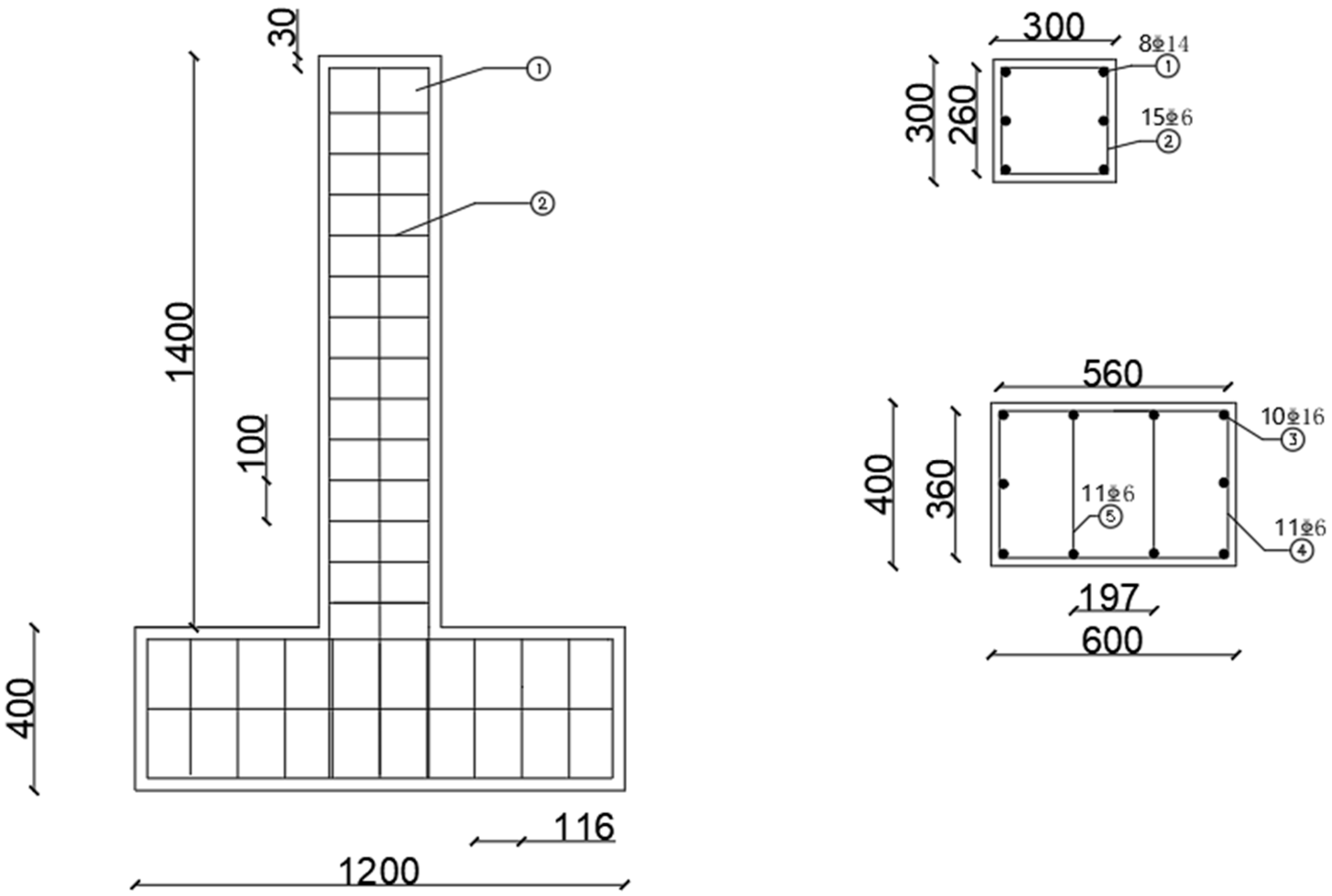
2. Experimental Program

2.1. Materials and Methods

The experiment was designed according to the “Code for Seismic Design of Buildings” (GB 50011-2010). T-shaped square columns were used in this experiment, and a total of 4 sections with dimensions of 300 mm × 300 mm were made, including one comparison column and three reinforcement columns. The reinforcement columns were reinforced using three reinforcement methods: prestressed steel wire rope reinforcement, polyurethane cement composite material reinforcement, and prestressed steel wire ropes embedded in polyurethane cement composite material reinforcement. The entire specimen is 1800 mm high, the column is 1400 mm high, and the concrete strength grade is C30. HRB400 is used for longitudinal reinforcement, HRB300 is used for hoop reinforcement, and the spacing between hoop reinforcement is 100 mm. The side section size of the column foundation is 400 mm × 600 mm, with a length of 1200 mm. All specimens use the same size and reinforcement. The parameters are shown in Figure 1 and Table 1. The loading method is shown in Figure 2.

2.2. Loading Method

This experiment was conducted at the Institute of Engineering Mechanics, China Earthquake Administration. A 300 ton electric servo hydraulic jack was used to apply constant pressure to each column, and a horizontal load was applied by controlling the MTS (mechanical testing and simulation) servo hydraulic brake. The experiment adopted a quasi-static test method of mixed loading of controlled load and displacement, and used symmetric constant amplitude cyclic loading. The initial horizontal load was 10 KN, and then it gradually increased in increments of 10 KN until the sample reached the yield. Subsequently, a displacement loading mode was adopted, with the sliding distance generated by the specimen during load-controlled yielding as the initial loading step, which was defined as Δ y and gradually increased afterwards in increments of Δ y . When the load dropped to 85% of the peak load, the specimen was considered to have failed and the experiment was completed.

3. Test Results and Discussion

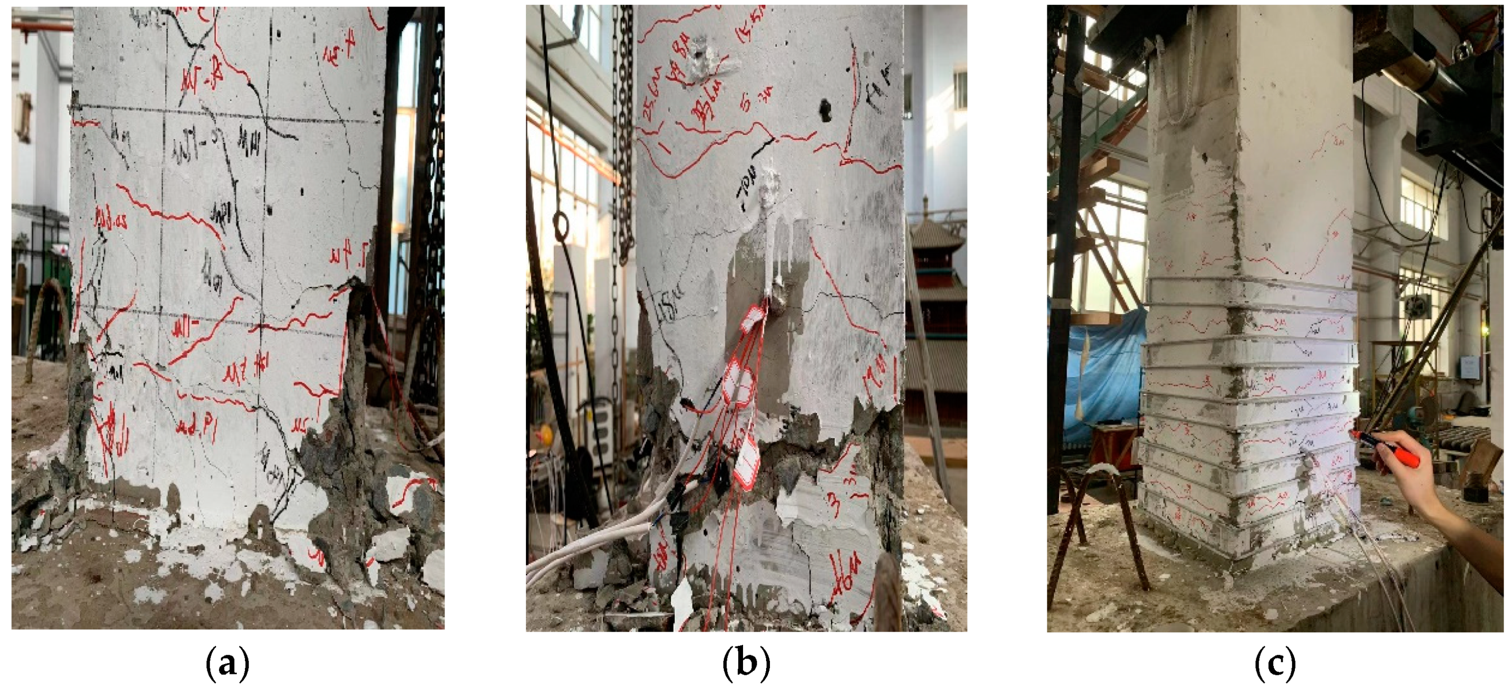
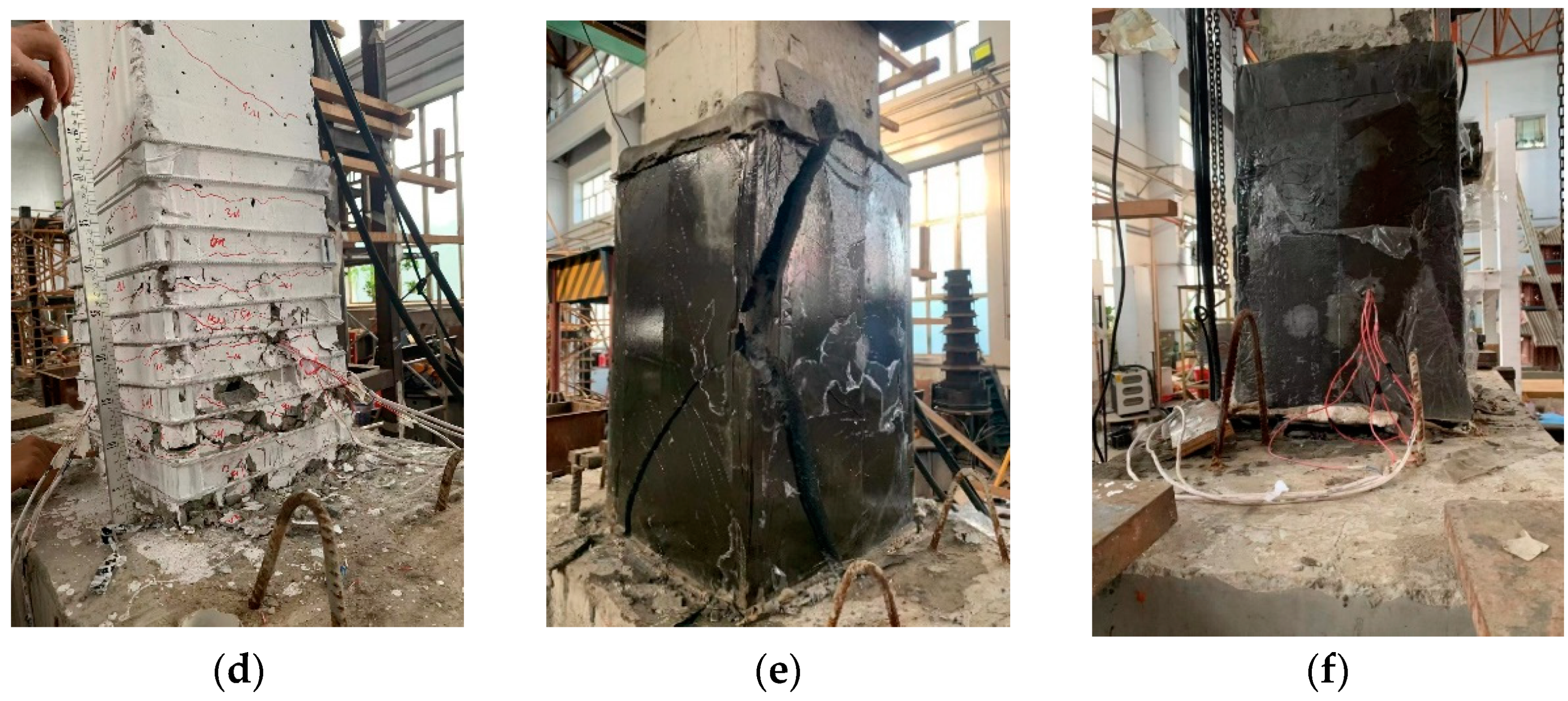
3.1. Destruction Process

As shown in Figure 3. Compared with unreinforced columns, the concrete in the plastic hinge area at the bottom of the unreinforced column falls off severely and produces large cracks, while the concrete in the plastic hinge area at the bottom of the prestressed steel wire rope-reinforced column does not show significant detachment and shows bulging failure. This indicates that the prestressed steel wire rope provides a tightening effect on the stress zone at the bottom of the column, thereby improving its compressive strength and ductility, and reducing the possibility of brittle failure. Both the polyurethane cement composite material-reinforced column and the prestressed steel wire rope-reinforced column did not exhibit significant brittle failure. This is because the reinforcement of both materials provides the column with the ability to resist deformation, thereby improving its ductility. Compared with unreinforced columns, the plastic hinge area at the bottom of the column reinforced with polyurethane cement composite material did not show concrete detachment, and only the reinforced material showed cracking on the surface of the reinforced area. This indicates that the polyurethane cement composite material has the ability to fully absorb the energy generated under load, thereby offsetting the influence of seismic action on the specimen and improving its ductility. Compared to unreinforced columns, prestressed steel wire ropes embedded in polyurethane cement composite-reinforced columns did not show cracking or concrete detachment in the plastic hinge zone during failure. Compared with prestressed steel wire rope-reinforced columns and polyurethane cement composite-reinforced columns, their bearing capacity increased by 58% and 45%, indicating that the two materials cannot only be well combined, but also resist and absorb energy under external loads. Moreover, both prestressed steel wire rope-reinforced columns and polyurethane cement composite-reinforced columns have varying degrees of damage under earthquake action, while there is no significant external damage to the specimens under mixed reinforcement of the two materials. This indicates that their ductility has been greatly improved under the combination of the two materials.

3.2. Load–Displacement Hysteresis Curve

The load–displacement hysteresis curves of all specimens are shown in Figure 4.
After the peak load occurs, the slope of the unreinforced column decreases sharply between the prestressed steel wire rope-reinforced specimens and the unreinforced specimens, while the downward trend of the prestressed steel wire rope-reinforced column shows a relatively gentle trend. This indicates that the prestressed steel wire rope exerts an active restraint force on the specimens to change their stress performance, improve their bearing capacity and ductility, and increase the corresponding hysteresis curve area. The prestressed steel wire rope also maintains linearity within the displacement range of 0–10 mm, and then reaches the peak load at 15 mm, corresponding to the maximum displacement reached, indicating an improvement in ductility. Compared to unreinforced columns and prestressed steel wire rope-reinforced columns, polyurethane cement composite material-reinforced columns have a more full hysteresis curve and cover a larger area. It can be seen that it exhibits elasticity before rupture. Before the longitudinal steel bars yield, the slope of loading and unloading does not change much, and the development of column failure is slower, with a smoother decrease in peak load. The hysteresis curve after yielding exhibits a “circular arc” shape. The residual deformation of the specimen is smaller, and the horizontal displacement and ductility increase.
From the hysteresis curve of the mixed reinforced column, it can be seen that in the initial stage of the experiment, the shape of the hysteresis curve is narrow, the energy consumption is small, the residual deformation is small, and the overall distribution of the curve is full. The sample is elastic before fracture and the slope of the loading and unloading parts does not change much before the longitudinal bars yield. When the load exceeds the yield load and displacement control is used, the energy dissipation capacity increases with the increase in the hysteresis loop area. The reinforced column gradually reaches the elastic–plastic stage, forming plastic hinges. After reaching the ultimate horizontal displacement, the horizontal load slowly decreases. In the middle of the curve, the phenomenon of “pinching” can be observed, and the characteristic of pinching behavior is the decrease in stiffness during unloading and reloading. When displacement is applied in one direction, shrinkage usually occurs through the opening and closing of cracks. This indicates that as displacement and number of cycles increase, the slope of the hysteresis curve continuously decreases, resulting in a gradual decrease in stiffness. The bonding performance between materials also decreases with the increase in residual deformation. Therefore, it leads to a steep decrease and poor ductility of the unreinforced column after reaching its peak load, while the decrease in the mixed reinforced column is the gentlest and has the best ductility.

3.3. Backbone Curves

The skeleton curve is the envelope curve obtained by connecting the extreme points of the loads applied in the same direction (tension or compression) on the hysteresis curve in sequential order. The skeleton curve represents the trajectory of the maximum peak reached during each cycle of loading, reflecting the stress and deformation characteristics of the component at different stages.
As shown in Figure 5, with the change in loading method, the strength and plasticity changes of each specimen tend to be consistent. It is worth noting that the unreinforced column is observed to be linear at displacement intervals of 0–5 mm. The lateral force increases with the increase in displacement and reaches its peak at 30 mm. Subsequently, due to its poor ductility, the load suddenly decreases with the increase in displacement. The changes in the prestressed steel wire rope-reinforced column and the polyurethane cement composite material-reinforced column are similar. The two reinforcement materials have little effect on the initial stiffness of the specimen, and the lateral force gradually increases with the increase in displacement. After reaching the peak load, the load slowly decreases with the increase in displacement. This proves that the ductility of the specimen is improved under the support of the two materials. It is worth noting that the curve coverage area and peak load of the polyurethane cement composite material-reinforced column are larger. Compared to the prestressed steel wire rope, the polyurethane cement composite material performs better in resisting earthquake action. The yield load and elastic deformation capacity of the specimens under mixed reinforcement are significantly improved. The skeleton curve of the plastic stage is also fully extended and developed, and the downward curve is also smoother. This indicates that after the specimen enters the elastic–plastic stage, its lateral stiffness, ultimate horizontal bearing capacity, and ultimate horizontal displacement all increase. Compared to the specimens reinforced with prestressed steel wire rope and polyurethane cement composite material alone, their ultimate horizontal bearing capacity has increased by 58% and 45%, and their ultimate displacement has increased by 50% and 28.5%.

3.4. Displacement Ductility

The calculated displacement ductility ratios and ultimate displacement ratios for all test specimens are presented in Table 2. From Figure 6, it can be seen that the displacement ductility of the reinforced column has been significantly improved compared to the pre-reinforced column, and the ultimate displacement ratio of the mixed reinforced column has increased the most, indicating that the mixed reinforcement has a more significant impact on the overall ductility of the specimen. It is worth noting that compared to the unreinforced column, the larger active constraint force increases the ductility of the specimen. Compared with the polyurethane cement composite material-reinforced column, the increase in prestress level has a similar effect, but the ductility performance of the polyurethane cement composite material is better. Compared with the first three specimens, the mixed reinforcement specimens have larger displacement ductility and a larger displacement ductility ratio. This is because the mixed reinforcement specimens have good deformation ability not only in the plastic stage but also in the elastic stage, leading to an increase in their yield displacement and yield strength.

3.5. Energy Dissipation Capacity

The cumulative dissipated energy is the total area enclosed by the hysteresis loops. Figure 7 illustrates the cumulative dissipated energy for all specimens.
From Figure 7, it can be seen that compared with the unreinforced column, the reinforced specimens significantly improved their energy dissipation capacity, especially the specimens with mixed reinforcement, which increased their energy dissipation capacity by 3.2 times. It can be concluded that the energy dissipation capacity of the specimen is most significantly improved under the mixed reinforcement of prestressed steel wire rope and polyurethane cement composite material, and this reinforcement method provides the best constraint effect for the specimen. When the specimen of this reinforcement method is subjected to low-cycle-repeated loading, it is not advisable to generate large enough cracks, and the plastic hinge area and compression area concrete are fully utilized. By comparing the prestressed steel wire rope and polyurethane cement composite material-reinforced columns, it can be seen that increasing active restraint can improve the energy dissipation capacity of the specimens, while the wrapping of polyurethane cement composite material can more effectively improve the energy dissipation capacity of the specimens compared to increasing the level of prestressing. Compared with the first three specimens, the energy dissipation capacity of the hybrid reinforced column has been significantly improved. When using a mixed reinforcement method, the overall stiffness of the column is uniform, and the plastic hinge area at the bottom of the column is conducive to achieving the full energy consumption capacity of the confined concrete. Compared with the first three specimens, its energy consumption capacity is increased by 202%, 146%, and 20%.

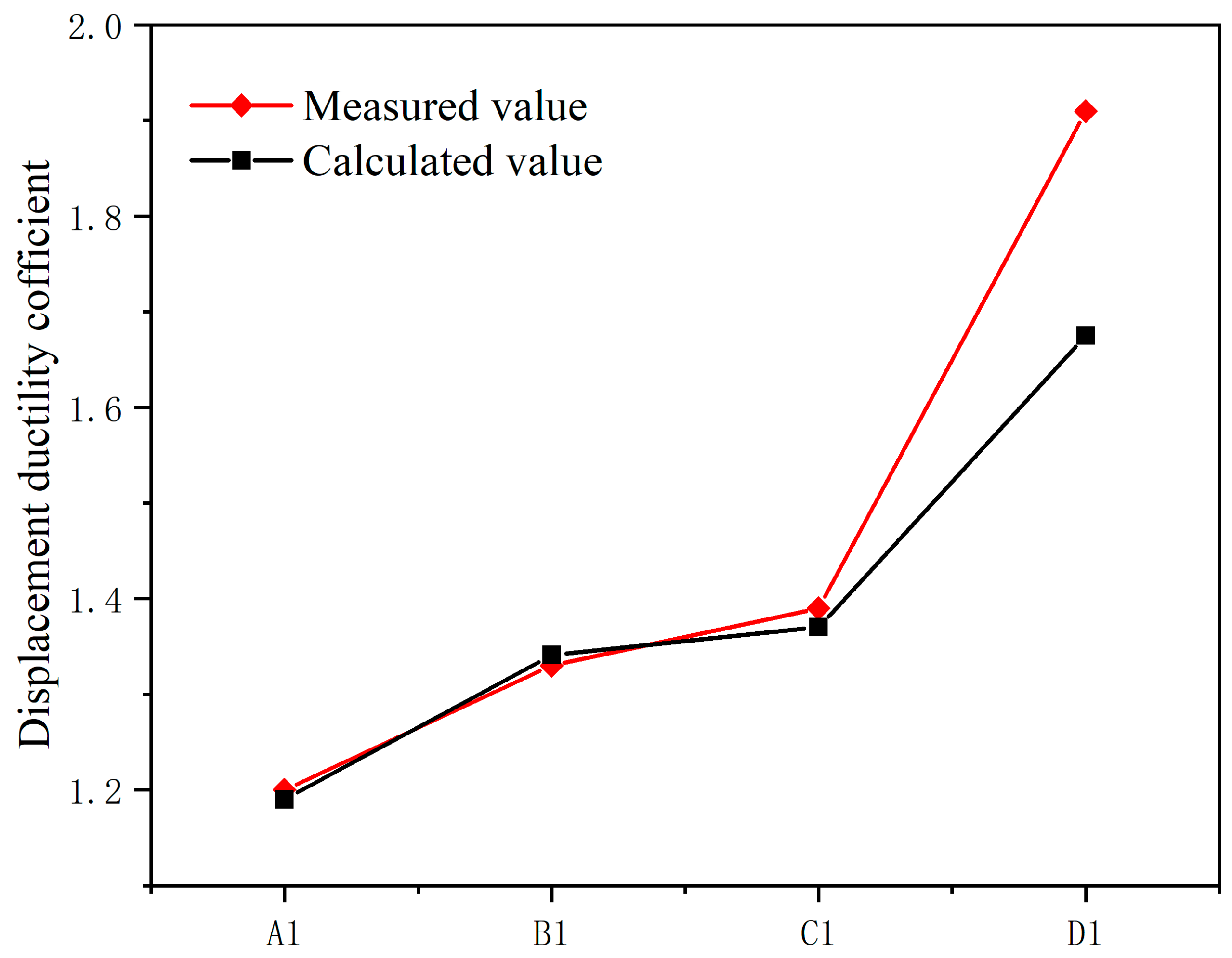
4. Calculated Ductility Coefficient of the Component

The displacement ductility coefficient of a structural component signifies its capacity to undergo plastic deformation. It is defined as the ratio of the ultimate displacement to the yield displacement of the component:
μ = Δ m Δ y
There are methods for modeling numerical equations, such as the differential orthogonal method [52], Bessel multi-step method [53], and finite difference method [54]. According to references [52,53,54,55,56,57] and experimental findings, it has been observed that the ductility coefficient of the component is associated with the axial load ratio, volumetric stirrup spacing characteristic value, and the volumetric stirrup characteristic value of the strengthening material. The approach for calculating the overall stirrup characteristic value is based on the methodology outlined in references [52,56] for the volumetric stirrup characteristic values provided for stirrups and carbon fibers:
λ e = λ v + v d λ C F S , v
v d = ε ¯ C F S ε u
In this paper, the impact of parameters including axial compression ratio, concrete strength grade, and overall characteristic value of reinforcement on the displacement ductility coefficient of RC columns is taken into consideration. A function is established based on the literature [51,52], with the following form:
μ = a + b α λ e c + d n
The characteristic value of overall reinforcement, λ e , can be computed using the following equation:
λ e = λ v + v d λ p s w r + v d λ p u c
λ v = ρ v f y v f t = A s v l v l 1 l 2 S 1 × f y v f t
λ p s w r = ρ p f p s w r f t = A p s w r l p s w r b h S 2 × f p s w r f t
λ p u c = ρ u f p u c f t = τ p u c l p u c b h × f p u c f t
The displacement ductility coefficient, calculated numerically, is employed as input data. Nonlinear regression analysis is executed in MATLAB2018b software to determine the regression coefficients. These coefficients are subsequently incorporated into the formula to derive the desired result:
μ = 3.401 λ e 0.173 0.805 + 0.956 n
Based on the formula for calculating the displacement ductility coefficient as described above, the experimental results of this study were analyzed and computed. As shown in the Figure 8 and Table 3, the calculated results demonstrate a high degree of agreement with the experimental results. This formula can serve as a reliable reference in practical engineering applications.

5. Conclusions

(1)
The analysis of experimental data shows that the seismic performance of RC columns with prestressed steel wire ropes embedded in polyurethane cement composite material has been significantly improved. Compared with unreinforced columns, its load displacement hysteresis curve covers a larger area and is more full, with a 69% increase in ultimate horizontal displacement and a 202% increase in energy dissipation capacity.
(2)
Compared with the unreinforced column, the prestressed steel wire rope reinforcement method and the polyurethane cement composite material reinforcement method only improve the ductility and energy dissipation capacity of the column. But the impact on the horizontal bearing capacity of the column is limited. But under the reinforcement method of prestressed steel wire ropes embedded in polyurethane cement composite material, the development of diagonal cracks is effectively suppressed, the initial damage is reduced, and not only are the horizontal bearing capacity and energy dissipation capacity improved, but also the ductility of the column.
(3)
Different reinforcement methods have different effects on the seismic performance of columns. The prestressed steel wire rope and polyurethane cement composite material have changed the active restraint force. With the increase in active restraint force, the seismic performance of reinforced columns, such as ductility, energy dissipation capacity, and horizontal bearing capacity, is enhanced to varying degrees. The prestressed steel wire rope has a significant impact on the stiffness and horizontal bearing capacity of the specimen, while the polyurethane cement composite material has a significant impact on the ductility and energy dissipation capacity of the specimen.
(4)
This article considers the influence of axial compression ratio, concrete strength grade, and overall reinforcement characteristic values on the displacement ductility coefficient of RC columns. A formula for calculating the displacement ductility coefficient is obtained through nonlinear regression, and the experimental and calculated values are in good agreement.

Author Contributions

Experimental, R.G., H.Z. and Y.S.; methodology, R.G., K.C. and Y.S.; software, R.G., H.Z. and K.C.; data curation, R.G., H.Z. and H.L.; validation, R.G., H.Z., K.C. and Y.S.; investigation, R.G., H.Z. and H.L.; resources, L.D. and Y.L.; writing—original draft preparation, R.G.; writing—review and editing, K.C., L.D. and Y.L.; supervision, L.D. and Y.L.; project administration, L.D.; funding acquisition, L.D. and Y.L. All authors have read and agreed to the published version of the manuscript.

Funding

Scientific Research Fund of Institute of Engineering Mechanics, China Earthquake Administration (Grant No. 2021 D13); Natural Science Foundation of Heilongjiang Province (grant number LH2023D022).

Data Availability Statement

The data used to support the findings of this study are included within the article.

Conflicts of Interest

The authors declare no conflict of interest. The funders had no role in the design of the study; in the collection, analyses, or interpretation of data; in the writing of the manuscript, or in the decision to publish the results.

Abbreviations

PSWRprestressed steel wire rope
pUCpolyurethane cement
S w represents the spacing of prestressed steel wire ropes
F i represents the control force for steel wire rope tensioning
F u represents the ultimate tensile force of the steel wire ropes
Δ y horizontal yield displacement
Δ m ultimate horizontal displacement
μdisplacement ductility ratio ( μ = Δ m Δ y )
δ u ultimate displacement ratio ( δ u = Δ m L ), where L is the height of the column)
Ecumulative energy dissipation
λ e represents the overall characteristic value of reinforcement
λ v denotes the characteristic value of stirrup reinforcement
λ C F S , v refers to the characteristic value of carbon fiber sheet reinforcement
v d stands for the effective confinement coefficient of the carbon fiber sheet in the field of civil engineering
ε ¯ C F S represents the average strain
ε u stands for the ultimate strain
α denotes the stirrup configuration coefficient
n represents the axial compression ratio
a, b, c, and dare undetermined regression coefficients
A s v area of a single shear reinforcement stirrup
l v perimeter of a single shear reinforcement stirrup
l 1   and   l 2 length of shear reinforcement stirrup sides
S 1 spacing between shear reinforcement stirrups
f y v tensile strength of shear reinforcement stirrup
f t tensile strength of concrete
A p s w r area of a single prestressing steel wire rope
l p s w r perimeter of a single prestressing steel wire rope
b   and   h width and height of the section
S 2 spacing of the prestressing steel wire ropes
f p s w r tensile strength of the prestressing steel wire rope
τ p u c   and   l p u c section thickness and total perimeter of polyurethane composite material
f p u c tensile strength of the polyurethane composite material

References

  1. GB 50011-2010; Chinese Standard, Code for Seismic Design of Buildings. Ministry of Housing and Urban-Rural Development of the People’s Republic of China: Beijing, China, 2016.
  2. Sharma, K.; Deng, L.; Noguez, C.C. Field investigation on the performance of building structures during the 25 April 2015 Gorkha earthquake in Nepal. Eng. Struct. 2016, 121, 61–74. [Google Scholar] [CrossRef]
  3. Zhao, B.; Taucer, F.; Rossetto, T. Field investigation on the performance of building structures during the 12 May 2008 Wenchuan earthquake in China. Eng. Struct. 2009, 31, 1707–1723. [Google Scholar] [CrossRef]
  4. Zhang, H.; Wang, T.; Lin, X.; Qu, Z.; Mao, C. Seismic damages of RC frames in Nepal Ms 8.1 earthquake. Eng. Mech. 2016, 33, 59–68. (In Chinese) [Google Scholar]
  5. Kawashima, K. Seismic performance of RC bridge piers in Japan: An evaluation after the 1995 Hyogo-ken nanbu earthquake. Prog. Struct. Eng. Mater. 2000, 2, 82–91. [Google Scholar] [CrossRef]
  6. Wang, W.L.; Wang, T.T.; Su, J.J.; Lin, C.H.; Seng, C.R.; Huang, T.H. Assessment of damage in mountain tunnels due to the Taiwan Chi-Chi Earthquake. Tunn. Undergr. Space Technol. 2001, 16, 133–150. [Google Scholar] [CrossRef]
  7. Shakir, Q.M.; Abdlsaheb, S.D. Rehabilitation of partially damaged high strength RC corbels by EB FRP composites and NSM steel bars. Structures 2022, 38, 652–671. Available online: http://gfbic3d25a792315f4bd8sf9kpnpnuuwf56nkw.fiac.hlju.cwkeji.cn/10.1016/j.istruc.2022.02.023 (accessed on 23 February 2022). [CrossRef]
  8. Shakir, Q.M.; Abdlsaheb, S.D. Strengthening of the Self-Compacted Reinforced Concrete Corbels Using NSM Steel Bars and CFRP Sheets Techniques. Eng. Sci. Technol. 2022, 7, 764–1780. [Google Scholar]
  9. Wei, Y.; Li, K.; Fan, J.; Li, Y.; Li, S. Seismic performance of RC columns strengthened with HSSSWR meshes reinforced ECC under high axial compression ratio. J. Build. Eng. 2023, 76, 107350. [Google Scholar] [CrossRef]
  10. Cao, J.; Hao, J.; Xue, Q.; Fan, C.; Sun, X. Seismic behavior of wall-type spiral stirrups-confined RC column to steel beam joint. J. Constr. Steel Res. 2023, 210, 108051. [Google Scholar] [CrossRef]
  11. Yadav, R.; Yuan, H.; Chen, B.; Lian, Z. Experimental study on seismic performance of latticed CFST-RC column connected with RC web. Thin-Walled Struct. 2018, 126, 258–265. [Google Scholar] [CrossRef]
  12. Shan, Z.; Looi, D.; Su, R. A novel seismic strengthening method of RC columns confined by direct fastening steel plates. Eng. Struct. 2020, 218, 110838. [Google Scholar] [CrossRef]
  13. Huang, H.; Hao, R.; Zhang, W.; Huang, M. Experimental study on seismic performance of square RC columns subjected to combined loadings. Eng. Struct. 2019, 184, 194–204. [Google Scholar] [CrossRef]
  14. Wang, Q.; Lv, J.; Lu, C.-L.; Zhu, W.-X. Experimental study on seismic performance of square RC columns strengthened with multi-layer prestressed CFRP fabric. J. Build. Eng. 2022, 45, 103589. [Google Scholar] [CrossRef]
  15. Wang, H.; Xing, G.; Zhao, J.; Wen, F. Seismic behavior of RC columns strengthened with near-surface-mounted aluminum alloy bars and CFRP wraps. Eng. Struct. 2022, 268, 114742. [Google Scholar] [CrossRef]
  16. Zhang, Y.; Tabandeh, A.; Ma, Y.; Gardoni, P. Seismic performance of precast segmental bridge columns repaired with CFRP wraps. Compos. Struct. 2020, 243, 112218. [Google Scholar] [CrossRef]
  17. Lu, C.-L.; Xiao, Y.-P.; Wang, Q.; Zhu, W.-X. Study on axial compressive properties of RC square columns strengthened with prestressed CFRP sheets. Structures 2020, 27, 2011–2024. [Google Scholar] [CrossRef]
  18. Wu, S.; Han, B.; Wu, Z.; Li, H.; Liu, H. Experimental study on axially compressed square RC stub columns strengthened with prestressed CFRP strips. IOP Conf. Ser. Mater. Sci. Eng. 2020, 782, 022104. [Google Scholar] [CrossRef]
  19. Ma, C.; Gao, H.; Li, K.; Liao, W.; Wang, Z.; Bai, Y. Experimental study on the seismic behavior of RC columns with high axial compression ratios retrofitted by large rupture strain fiber-reinforced polymer. Eng. Struct. 2023, 277, 115448. [Google Scholar] [CrossRef]
  20. Cao, Y.; Li, L.; Liu, M.; Wu, Y. Mechanical behavior of FRP confined rubber concrete under monotonic and cyclic loading. Compos. Struct. 2021, 272, 114205. [Google Scholar] [CrossRef]
  21. Zhou, Y.; Chen, X.; Wang, X.; Sui, L.; Huang, X.; Guo, M.; Hu, B. Seismic performance of large rupture strain FRP retrofitted RC columns with corroded steel reinforcement. Eng. Struct. 2020, 216, 110744. [Google Scholar] [CrossRef]
  22. Moran, D.A.; Pantelides, C.P.; Reaveley, L.D. Mohr-coulomb model for rectangular and square FRP-confined concrete. Compos. Struct. 2019, 209, 889–904. [Google Scholar] [CrossRef]
  23. Dirikgil, T. Experimental investigation of the effects of concrete strength and axial load ratio on the performances of CFRP-wrapped and externally collared RC short columns. Eng. Struct. 2021, 230, 111647. [Google Scholar] [CrossRef]
  24. Zhao, J.; Ren, W.; Ruan, X.; Gong, X.; Si, C. Experimental Study on the Seismic Performance of Columns Reinforced by the CFRP Bar and Sheet. Appl. Compos. Mater. 2021, 28, 1291–1313. [Google Scholar] [CrossRef]
  25. Zeng, Z.; Jiang, S.; Deng, K.; Huang, H.; Cui, E. Seismic performance of circular RC columns strengthened in flexure using NSM reinforcement and externally bonded BFRP sheets. Eng. Struct. 2022, 256, 114033. [Google Scholar] [CrossRef]
  26. Mei, S.-J.; Bai, Y.-L.; Dai, J.-G.; Han, Q. Seismic behaviour of shear critical square RC columns strengthened by large rupture strain FRP. Eng. Struct. 2023, 280, 115679. [Google Scholar] [CrossRef]
  27. Bai, Y.-L.; Dai, J.-G.; Mohammadi, M.; Lin, G.; Mei, S.-J. Stiffness-based design-oriented compressive stress-strain model for large-rupture-strain (LRS) FRP-confined concrete. Compos. Struct. 2019, 223, 110953. [Google Scholar] [CrossRef]
  28. Ueda, T. Material Mechanical Properties Necessary for the Structural Intervention of Concrete Structures. Engineering 2019, 5, 1131–1138. [Google Scholar] [CrossRef]
  29. Ye, Y.-Y.; Liang, S.-D.; Feng, P.; Zeng, J.-J. Recyclable LRS FRP composites for engineering structures: Current status and future opportunities. Compos. Part B Eng. 2021, 212, 108689. [Google Scholar] [CrossRef]
  30. Bai, Y.-L.; Dai, J.-G.; Teng, J.G. Cyclic Compressive Behavior of Concrete Confined with Large Rupture Strain FRP Composites. J. Compos. Constr. 2014, 18, 04013025. [Google Scholar] [CrossRef]
  31. Bai, Y.-L.; Zhang, Y.-F.; Jia, J.-F.; Mei, S.-J.; Han, Q.; Dai, J.-G. Simplified plasticity damage model for large rupture strain (LRS) FRP-confined concrete. Compos. Struct. 2022, 280, 114916. [Google Scholar] [CrossRef]
  32. Bai, Y.-L.; Bai, S.-C.; Mei, S.-J.; Jia, J.-F.; Yang, K. Seismic behavior of RC square columns strengthened with LRS FRP under high axial load ratio. Structures 2023, 56, 104867. [Google Scholar] [CrossRef]
  33. Tan, J.-Y.; Chin, C.-L.; Ma, C.-K.; Ong, C.-B.; Awang, A.Z.; Omar, W.; Lam, S.-K. Pre-tensioned steel straps for seismic retrofit of reinforced concrete columns under combined loading of flexure, shear and torsion. Structures 2023, 56, 104935. [Google Scholar] [CrossRef]
  34. Zhang, Y.; Deng, M.; Li, T.; Dong, Z. Strengthening of flexure-dominate RC columns with ECC jackets: Experiment and analysis. Eng. Struct. 2021, 231, 111809. [Google Scholar] [CrossRef]
  35. Jin, L.; Liang, J.; Chen, F.; Du, X. Size effect on the seismic behavior of square CFST short columns. J. Constr. Steel Res. 2022, 199, 107589. [Google Scholar] [CrossRef]
  36. Qiao, D.-H.; Xu, Y.-Q.; Zhang, X.; Pang, J.-B.; Liu, K.; Wang, S.-J. Seismic behaviour and size effect of column base joints with inverted exposed grouted sleeves. J. Build. Eng. 2022, 51, 104333. [Google Scholar] [CrossRef]
  37. Jin, L.; Wan, S.; Li, D.; Du, X. Size effect and strain rate effect on seismic behavior of reinforced concrete beam-column joints. Struct. Concr. 2022, 23, 1453–1468. [Google Scholar] [CrossRef]
  38. Zhang, K.; Yuan, Q.; Huang, T.; Zuo, S.; Yao, H. Utilization of novel stranded steel fiber to enhance fiber–matrix interface of cementitious composites. Constr. Build. Mater. 2023, 369, 130525. [Google Scholar] [CrossRef]
  39. Liu, Z.-Q.; Guo, Z.-X.; Ye, Y. Flexural behaviour of RC beams strengthened with prestressed steel wire ropes polymer mortar composite. J. Asian Arch. Build. Eng. 2021, 21, 48–65. [Google Scholar] [CrossRef]
  40. Zhang, Y. Experimental and theoretical analysis of flexural reinforcement performance of prestressed high-strength soft steel wire with polymer mortar. Chin. J. Highw. 2017, 30, 10. [Google Scholar]
  41. Huang, H.; Liu, B.; Xi, K. Interfacial tensile bond behavior of permeable polymer mortar to concrete-sciencedirect. Constr. Build. Mater. 2016, 121, 210–221. [Google Scholar] [CrossRef]
  42. Hou, N.; Li, J.; Li, X.; Cui, Y.; Xiong, D.; Cui, X. Study on Toughening and Temperature Sensitivity of Polyurethane Cement (PUC). Materials 2022, 15, 4318. [Google Scholar] [CrossRef]
  43. Wang, Y.; Sun, Q. Experimental Research on T-beam Bridge Reinforced with Polyurethane Cement Prestressed Steel Wire Rope. In Proceedings of the 9th Annual Academic Conference of the Maintenance and Management Branch of China Highway Society, Dalian, China, 8–9 June 2019. [Google Scholar]
  44. Yuan, F.; Shao, Y. Experimental Study on Flexural Strengthening of RC Beam Reinforced with High Strength Steel Wire Net-Engineered Cementitious Composites. Railw. Eng. 2021, 61, 33–38. [Google Scholar]
  45. Yang, N.; Yang, X. Self-Monitoring of Reinforced Concrete Beam Bending with Carbon Nanofiber Polyurethane Composite. Adv. Civ. Eng. 2022, 2022, 7294899. [Google Scholar] [CrossRef]
  46. Vijayaraghavan, J.; Jeevakkumar, R.; Venkatesan, G.; Rengasamy, M.; Thivya, J. Influence of kaolin and dolomite as filler on bond strength of polyurethane coated reinforcement concrete. Constr. Build. Mater. 2022, 325, 126675. [Google Scholar] [CrossRef]
  47. Hussain, H.K.; Liu, G.W.; Yong, Y.W. Experimental study to investigate mechanical properties of new material polyurethane–cement composite (PUC). Constr. Build. Mater. 2014, 50, 200–208. [Google Scholar] [CrossRef]
  48. Gao, H. Shear Behavior of Reinforced Concrete Beams Strengthen by Prestressed Steel Wire Ropes Embedded in Polyurethane Cement Composite (PSWR-PUC). Ph.D. Thesis, Northeast Forestry University, Harbin, China, 2021. [Google Scholar] [CrossRef]
  49. Hussain, H.K.; Lian, Z.Z.; Gui, W.L. An experimental study on strengthening reinforced concrete T-beams using new material poly-urethane-cement (PUC). Constr. Build. Mater. 2013, 40, 104–117. [Google Scholar] [CrossRef]
  50. Zhang, K.; Sun, Q. Experimental Study of Reinforced Concrete T-Beams Strengthened with a Composite of Prestressed Steel Wire Ropes Embedded in Polyurethane Cement (PSWR–PUC). Int. J. Civ. Eng. 2018, 16, 1109–1123. [Google Scholar] [CrossRef]
  51. Zhang, K.; Qi, T.; Zhu, Z.; Xue, X.; Shen, X. Strengthening of a Reinforced Concrete Bridge with a Composite of Prestressed Steel Wire Ropes Embedded in Polyurethane Cement. J. Perform. Constr. Facil. 2021, 35, 5. [Google Scholar] [CrossRef]
  52. Zhang, K.; Shen, X.; Liu, J.; Teng, F.; Zhang, G.; Wang, J. Flexural strengthening of reinforced concrete T-beams using a composite of prestressed steel wire ropes embedded in polyurethane cement (PSWR-PUC): Theoretical analysis. Structures 2022, 44, 1278–1287. [Google Scholar] [CrossRef]
  53. Bert, C.W.; Malik, M. Differential quadrature: A powerful new technique for analysis of composite structures. Compos. Struct. 1997, 39, 179–189. [Google Scholar] [CrossRef]
  54. Kabir, H.; Aghdam, M.M. A generalized 2D Bézier-based solution for stress analysis of notched epoxy resin plates reinforced with graphene nanoplatelets. Thin-Walled Struct. 2021, 169, 108484. [Google Scholar] [CrossRef]
  55. Wang, Y.; Gu, Y.; Liu, J. A domain-decomposition generalized finite difference method for stress analysis in three-dimensional composite materials. Appl. Math. Lett. 2020, 104, 106226. [Google Scholar] [CrossRef]
  56. Yu, W.H. Study on Ductility Performance of Reinforced High concrete Columns Confined by CFRP; Dalian University of Technology: Dalian, China, 2010. (In Chinese) [Google Scholar]
  57. Chen, L. Experimental Study of the Seismic Behavior of RC Column Strengthened with High Strength Steel Wire. Ph.D. Thesis, Nie Jianguo Tsinghua University, Beijing, China, 2004. [Google Scholar]
Figure 1. Column reinforcement detail drawing.
Buildings 14 00993 g001
Figure 2. Experimental lateral cyclic loading.
Buildings 14 00993 g002
Figure 3. Specimen failure mode. Note: (a,b)—unreinforced specimen; (c,d)—prestressed wire rope-reinforced specimen; (e)—polyurethane cement composite-reinforced specimen; (f)—prestressed wire rope embedded in polyurethane cement composite-reinforced specimen.
Buildings 14 00993 g003aBuildings 14 00993 g003b
Figure 4. Hysteresis curve: (a)—unreinforced specimen; (b)—prestressed wire rope-reinforced specimen; (c)—polyurethane cement composite-reinforced specimen; (d)—prestressed wire rope in polyurethane cement composite-reinforced specimen.
Buildings 14 00993 g004
Figure 5. Backbone curves: A1—unreinforced specimen; B1—specimen reinforced with prestressed steel wire rope; C1—specimen reinforced with polyurethane cement composite; D1—specimen reinforced with both prestressed steel wire rope and polyurethane cement composite.
Buildings 14 00993 g005
Figure 6. Displacement ductility curve: (a)—unreinforced specimen; (b)—specimen reinforced with prestressed steel wire rope; (c)—specimen reinforced with polyurethane cement composite; (d)—specimen reinforced with both prestressed steel wire rope and polyurethane cement composite.
Buildings 14 00993 g006
Figure 7. Cumulative dissipated energy of each specimen.
Buildings 14 00993 g007
Figure 8. Comparison of measured and calculated displacement ductility coefficients.
Buildings 14 00993 g008
Table 1. Specimen basic parameter design table.
Specimen NumberReinforcement MethodPrestressed Steel Wire Arrangement
S w (mm) F i (KN)Number of Individuals F i / F u
A1/////
B1PSWR300.5200.4
C1PUC////
D1PSWR + PUC300.5200.4
Note: Please refer to the symbol table for symbol information.
Table 2. Test results.
Specimen Number Δ y (mm) Δ m (mm)μ δ u E (KN·mm)
A 1 40.448.51.200.035103,873.82
B 1 45.160.21.330.043127,447.32
C 1 44.762.31.390.045265,032.78
D 1 45.987.81.910.063313,414.19
Note: Please refer to the symbol table for symbol information.
Table 3. Calculation results.
λ e Measured ValueCalculated ValueM/C
0.351.201.191.01
0.761.331.340.99
0.791.391.371.01
0.831.911.671.14
Disclaimer/Publisher’s Note: The statements, opinions and data contained in all publications are solely those of the individual author(s) and contributor(s) and not of MDPI and/or the editor(s). MDPI and/or the editor(s) disclaim responsibility for any injury to people or property resulting from any ideas, methods, instructions or products referred to in the content.

